McDewey
/mcpPage 7
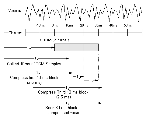
↗ View in doc contextThe top line of the figure depicts a sample voice wave form. The second line is a time scale in 10 ms
increments. At T0, the CS-ACELP algorithm begins to collect PCM samples from the codec. At T1,
the algorithm has collected its first 10 ms block of samples and begins to compress it. At T2, the first
block of samples has been compressed. In this example the compression time is 2.5 ms, as indicated
by T2-T1.
The second and third blocks are collected at T3 and T4. The third block is compressed at T5. The
packet is assembled and sent (assumed to be instantaneous) at T6. Due to the pipelined nature of the
Compression and Packetization processes, the delay from when the process begins to when the voice
frame is sent is T6-T0, or approximately 32.5 ms.
For illustration, this example is based on best case delay. If the worst case delay is used, the figure is
40 ms, 10 ms for Coder delay and 30 ms for Packetization delay.
Note that these examples neglect to include algorithmic delay.
Serialization Delay
Serialization delay (σn) is the fixed delay required to clock a voice or data frame onto the network
interface. It is directly related to the clock rate on the trunk. At low clock speeds and small frame
sizes, the extra flag needed to separate frames is significant.
Table 5.3 shows the serialization delay required for different frame sizes at different line speeds.
This table uses total frame size, not payload size, for computation.
Table 5.3: Serialization Delay in Milliseconds for Different Frame Sizes
Frame
Line Speed (Kbps)
Page 7 of 18
Cisco - Understanding Delay in Packet Voice Networks
7/31/2008
http://kbase.cisco.com/paws/servlet/ViewFile/5125/delay-details.xml?convertPaths=1