Document Metadata
Format: PDF
Title: Cisco ATA 191 and ATA 192 Analog Telephone Adapter Administration Guide for Multiplatform Firmware
Author: Andrew Mann
Creator: DITA Open Toolkit
Page 1
Cisco ATA 191 and ATA 192 Analog Telephone Adapter Administration
Guide for Multiplatform Firmware
First Published: 2018-02-05
Last Modified: 2025-04-10
Americas Headquarters
Cisco Systems, Inc.
170 West Tasman Drive
San Jose, CA 95134-1706
USA
http://www.cisco.com
Tel: 408 526-4000
800 553-NETS (6387)
Fax: 408 527-0883


Page 2
THE SPECIFICATIONS AND INFORMATION REGARDING THE PRODUCTS IN THIS MANUAL ARE SUBJECT TO CHANGE WITHOUT NOTICE. ALL STATEMENTS,
INFORMATION, AND RECOMMENDATIONS IN THIS MANUAL ARE BELIEVED TO BE ACCURATE BUT ARE PRESENTED WITHOUT WARRANTY OF ANY KIND,
EXPRESS OR IMPLIED. USERS MUST TAKE FULL RESPONSIBILITY FOR THEIR APPLICATION OF ANY PRODUCTS.
THE SOFTWARE LICENSE AND LIMITED WARRANTY FOR THE ACCOMPANYING PRODUCT ARE SET FORTH IN THE INFORMATION PACKET THAT SHIPPED WITH
THE PRODUCT AND ARE INCORPORATED HEREIN BY THIS REFERENCE. IF YOU ARE UNABLE TO LOCATE THE SOFTWARE LICENSE OR LIMITED WARRANTY,
CONTACT YOUR CISCO REPRESENTATIVE FOR A COPY.
The following information is for FCC compliance of Class A devices: This equipment has been tested and found to comply with the limits for a Class A digital device, pursuant to part 15
of the FCC rules. These limits are designed to provide reasonable protection against harmful interference when the equipment is operated in a commercial environment. This equipment
generates, uses, and can radiate radio-frequency energy and, if not installed and used in accordance with the instruction manual, may cause harmful interference to radio communications.
Operation of this equipment in a residential area is likely to cause harmful interference, in which case users will be required to correct the interference at their own expense.
The following information is for FCC compliance of Class B devices: This equipment has been tested and found to comply with the limits for a Class B digital device, pursuant to part 15 of
the FCC rules. These limits are designed to provide reasonable protection against harmful interference in a residential installation. This equipment generates, uses and can radiate radio
frequency energy and, if not installed and used in accordance with the instructions, may cause harmful interference to radio communications. However, there is no guarantee that interference
will not occur in a particular installation. If the equipment causes interference to radio or television reception, which can be determined by turning the equipment off and on, users are
encouraged to try to correct the interference by using one or more of the following measures:
• Reorient or relocate the receiving antenna.
• Increase the separation between the equipment and receiver.
• Connect the equipment into an outlet on a circuit different from that to which the receiver is connected.
• Consult the dealer or an experienced radio/TV technician for help.
Modifications to this product not authorized by Cisco could void the FCC approval and negate your authority to operate the product.
The Cisco implementation of TCP header compression is an adaptation of a program developed by the University of California, Berkeley (UCB) as part of UCB’s public domain version of
the UNIX operating system. All rights reserved. Copyright © 1981, Regents of the University of California.
NOTWITHSTANDING ANY OTHER WARRANTY HEREIN, ALL DOCUMENT FILES AND SOFTWARE OF THESE SUPPLIERS ARE PROVIDED "AS IS" WITH ALL FAULTS.
CISCO AND THE ABOVE-NAMED SUPPLIERS DISCLAIM ALL WARRANTIES, EXPRESSED OR IMPLIED, INCLUDING, WITHOUT LIMITATION, THOSE OF
MERCHANTABILITY, FITNESS FOR A PARTICULAR PURPOSE AND NONINFRINGEMENT OR ARISING FROM A COURSE OF DEALING, USAGE, OR TRADE PRACTICE.
IN NO EVENT SHALL CISCO OR ITS SUPPLIERS BE LIABLE FOR ANY INDIRECT, SPECIAL, CONSEQUENTIAL, OR INCIDENTAL DAMAGES, INCLUDING, WITHOUT
LIMITATION, LOST PROFITS OR LOSS OR DAMAGE TO DATA ARISING OUT OF THE USE OR INABILITY TO USE THIS MANUAL, EVEN IF CISCO OR ITS SUPPLIERS
HAVE BEEN ADVISED OF THE POSSIBILITY OF SUCH DAMAGES.
Any Internet Protocol (IP) addresses and phone numbers used in this document are not intended to be actual addresses and phone numbers. Any examples, command display output, network
topology diagrams, and other figures included in the document are shown for illustrative purposes only. Any use of actual IP addresses or phone numbers in illustrative content is unintentional
and coincidental.
All printed copies and duplicate soft copies of this document are considered uncontrolled. See the current online version for the latest version.
Cisco has more than 200 offices worldwide. Addresses and phone numbers are listed on the Cisco website at www.cisco.com/go/offices.
Cisco and the Cisco logo are trademarks or registered trademarks of Cisco and/or its affiliates in the U.S. and other countries. To view a list of Cisco trademarks, go to this URL:
https://www.cisco.com/c/en/us/about/legal/trademarks.html. Third-party trademarks mentioned are the property of their respective owners. The use of the word partner does not imply a
partnership relationship between Cisco and any other company. (1721R)
© 2025 Cisco Systems, Inc. All rights reserved.
Page 3
C O N T E N T S
Get Started
1
C H A P T E R 1
Your Analog Telephone Adapter
1
ATA 191 and ATA 192 Top Panel
2
Problem Report Tool Button
3
ATA 191 and ATA 192 Back Panel
3
Install Your Cisco ATA
5
ATA Voice Quality
5
Supported Codecs
5
SIP Proxy Redundancy
6
SIP Proxy Failover
6
SIP Proxy Fallback
7
Other ATA Voice Quality Features
9
New and Changed Information
13
C H A P T E R 2
New and Changed for Firmware Release 11.3(1)
13
New and Changed for Firmware Release 11.2(5)
14
New and Changed for Firmware Release 11.2(4)
14
New and Changed for Firmware Release 11.2(3)
15
New and Changed for Firmware Release 11.2(2)
15
New and Changed for Firmware Release 11.2(1)
15
Quick Setup for Voice over IP Service
17
C H A P T E R 3
Set Up Voice over IP
17
Network Configuration
19
C H A P T E R 4
Web-Based Configuration Utility
19
Cisco ATA 191 and ATA 192 Analog Telephone Adapter Administration Guide for Multiplatform Firmware
iii

Page 4
Access the Phone Web Interface
19
Allow Web Access to the ATA
20
Change Password after an Initial Registration or a Factory Reset
20
Basic Setup
21
Network Service (ATA 192 Only)
21
Basic Settings
21
IPv4 Settings
22
IPv6 Settings
23
IPv4 LAN Settings (ATA 192 Only)
25
IPv6 LAN Setting (ATA 192 Only)
27
Time Settings
27
Advanced Settings
28
Port Setting (ATA 192 Only)
28
MAC Address Clone
29
VPN Passthrough (ATA 192 Only)
29
VLAN
30
CDP and LLDP
30
Application
31
Quality of Service (QoS) (ATA 192 Only)
31
Port Forwarding (ATA 192 Only)
31
Manually Add Port Forwarding (ATA 192 Only)
32
DMZ (ATA 192 Only)
33
HTTP Proxy (ATA 191 and 192)
34
Voice Settings Configuration
37
C H A P T E R 5
Information
37
Product Information
37
System Status
38
Line 1 and Line 2 Settings (PHONE 1 and PHONE 2)
38
Custom CA Status
38
Provision Status
39
MIC Cert Refresh Status
39
System
41
System Configuration
41
Cisco ATA 191 and ATA 192 Analog Telephone Adapter Administration Guide for Multiplatform Firmware
iv
Contents
Page 5
Miscellaneous Settings
42
Security Settings
43
SIP
44
SIP Parameters
45
SIP Timer Values
47
Response Status Code Handling
49
RTP Parameters
49
SDP Payload Types
52
NAT Support Parameters
53
Provisioning
54
Configuration Profile
55
Firmware Upgrade
57
CA Settings
58
General Purpose Parameters
59
MIC Cert Settings
59
Regional
59
Ring, Cadence, and Tone Scripts
59
CadScript
59
FreqScript
60
ToneScript
61
Call Progress Tones
62
Distinctive Ring Patterns
64
Distinctive Call Waiting Tone Patterns
64
Distinctive Ring/CWT Pattern Names
65
Ring and Call Waiting Tone Spec
66
Control Timer Values (Sec)
67
Vertical Service Activation Codes
68
Vertical Service Announcement Codes
73
Outbound Call Codec Selection Codes
74
Miscellaneous
75
Line 1 and Line 2 Settings (PHONE 1 and PHONE 2)
76
General
77
Streaming Audio Server (SAS)
77
NAT Settings
78
Cisco ATA 191 and ATA 192 Analog Telephone Adapter Administration Guide for Multiplatform Firmware
v
Contents
Page 6
Network Settings
79
SIP Settings
80
Set up a Secure Line
84
Call Feature Settings
85
E911 Geolocation Configuration
86
Proxy and Registration
87
Subscriber Information
90
Supplementary Service Subscription
91
Audio Configuration
94
Dial Plan
98
FXS Port Polarity Configuration
99
User 1 and User 2
99
Call Forward Settings
100
Selective Call Forward Settings
100
Speed Dial Settings
101
Supplementary Service Settings
101
Distinctive Ring Settings
103
Ring Settings
103
Administration Settings
105
C H A P T E R 6
Management
105
Web Access Management
105
Cisco ATA 191 Web Access Fields
105
Cisco ATA 192 Web Access Fields
106
Cisco ATA 192 Remote Access Fields
106
TR-069
108
SNMP
108
SNMP Settings
109
SNMPv3 Settings
109
Trap Configuration
110
User List (Password Management)
110
Update a Password
110
Bonjour
111
Reset Button
111
Cisco ATA 191 and ATA 192 Analog Telephone Adapter Administration Guide for Multiplatform Firmware
vi
Contents
Page 7
SSH
111
Log
111
Debug Log Module
111
Debug Log Setting
112
Debug Log Viewer
112
Event Log Setting
113
PRT Viewer
113
Generate a Problem Report Remotely
114
PCM Viewer
114
CSS Dump
115
Crash Dump
115
Factory Defaults
116
Firmware Upgrade
116
ATA with Firmware Release 11.1.0MSR3-9 and Older Doesn't Upgrade
117
Configuration Management
117
Backup Configuration
117
Restore Configuration
117
Reboot
118
Status and Statistics
119
C H A P T E R 7
System Information
119
Interface Information
120
Network Status
121
Port Statistics (ATA 192 Only)
122
Memory Information
122
DHCP Server Information (ATA 192 Only)
123
Frequently Asked Questions
125
C H A P T E R 8
I Can't Connect to the Internet Through the ATA
125
I Upgraded my Firmware and the ATA doesn't Work Properly
126
I Can't use the DSL Service to Connect Manually to the Internet
126
There is no Dial Tone, and the Phone 1 or 2 LED is not Solid Green
126
When I place an Internet Phone Call, the Audio Breaks Up
126
Cisco ATA 191 and ATA 192 Analog Telephone Adapter Administration Guide for Multiplatform Firmware
vii
Contents
Page 8
When I Open a Web Browser, I am Prompted for a Username and Password. How can I Bypass this
Prompt?
127
The DSL Telephone Line Does Not Fit in the ATA WAN (Internet) Port.
127
My Modem Doesn't Have an Ethernet Port
127
The ATA Doesn't Have a Coaxial port for the Cable Connection
127
Call Statistics are Not Available in the Server
128
IVR for Administration
129
C H A P T E R 9
Use IVR for Administration
129
IVR Tips
129
IVR Actions
130
Advanced Options for Phone Services
135
C H A P T E R 1 0
Optimize Fax Completion Rates
135
Troubleshoot Your Fax
136
Dial Plan Configuration
137
Digit Sequences
137
Acceptance and Transmission of the Dialed Digits
140
Dial Plan Timer (Off-Hook Timer)
141
Interdigit Long Timer (Incomplete Entry Timer)
141
Interdigit Short Timer (Complete Entry Timer)
142
Reset the Control Timers
142
Emergency Calls
143
Emergency Call Support Background
143
Emergency Call Support Terminology
143
Configure the ATA to Make Emergency Calls
144
Cisco ATA 191 and ATA 192 Analog Telephone Adapter Administration Guide for Multiplatform Firmware
viii
Contents
Page 9
C H A P T E R 1
Get Started
• Your Analog Telephone Adapter, on page 1
• Install Your Cisco ATA , on page 5
• ATA Voice Quality, on page 5
Your Analog Telephone Adapter
The ATA 191 and ATA 192 analog telephone adapters are telephony-device-to-Ethernet adapters that allow
regular analog phones to operate on IP-based telephony networks. Both models support two voice ports, each
with an independent phone number. Both have an RJ-45 10/100BASE-T data port while the ATA 192 has an
additional Ethernet port.
The ATA connects to the Internet through a broadband (DSL or cable) modem or router. The ATA can be
used with an on-site call-control system or an Internet-based call-control system.
The ATA is an intelligent low-density Voice over IP (VoIP) gateway that enables carrier-class residential and
business IP Telephony services delivered over broadband or high-speed Internet connections. An ATA
maintains the state of each call it terminates and reacts appropriately to user input events (such as on/off hook
or hook flash). The ATAs use the Session Initiation Protocol (SIP) open standard so there is on/off hook or
hook flash. The ATAs use the Session Initiation Protocol (SIP) open standard so there is little or no involvement
by a “middle-man” server or media gateway controller. SIP allows inter-operation with all ITSPs that support
SIP.
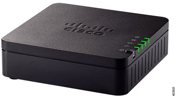
Figure 1: Cisco Analog Telephone Adapter
Cisco ATA 191 and ATA 192 Analog Telephone Adapter Administration Guide for Multiplatform Firmware
1

Page 10
ATA 191 and ATA 192 Top Panel
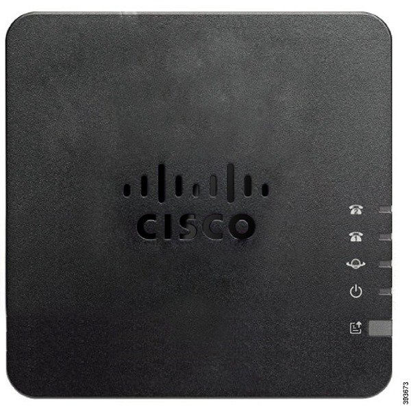
The following figure shows the different LEDs and buttons found on the top of your ATA.
Figure 2: ATA 191 and ATA 192 Top Panel
Table 1: ATA 191 and ATA 192 Top Panel Items
Description
Item
Steady green: System booted up successfully and is ready for use.
Slow flashing green: System is booting up.
Fast flashing green three times, then repeats: System failed to boot
up.
Fast flashing green: The LED behaviour occurs in the following
situations:
• System detects a factory reset.
To perform a factory reset, press and hold the RESET button for
about 10 seconds.
• A factory reset is performed successfully.
Off: Power is off.
Power LED
Flashing green: Data transmission or reception is in progress through
the WAN port.
Off: No link.
Network LED
Cisco ATA 191 and ATA 192 Analog Telephone Adapter Administration Guide for Multiplatform Firmware
2
Get Started
ATA 191 and ATA 192 Top Panel


Page 11
Description
Item
Steady green: On hook.
Slow flashing green: Off hook.
Fast flashing green three times, then repeats: The analog device failed
to register.
Fast flashing green: A factory reset is performed successfully.
Off: The port is not configured.
Phone 1 LED
Phone 2 LED
Press this button to create a problem report using the Problem Report
Tool.
Note
This button is not a power button. When you press this button, a problem
report is generated and uploaded to a server for the system administrator.
Problem Report Tool (PRT) Button
Flashing amber: The PRT is preparing the data for the problem report.
Fast Flashing amber: The PRT is sending the problem report log to
the HTTP server.
Solid amber: The activation of the FIPS mode failed. Press the PRT
button to turn off the PRT LED.
Solid green for five seconds, then off: The PRT report was sent
successfully.
Fast flashing green: A factory reset is performed successfully.
Flashing red: The PRT report failed. Press the PRT button once to
cancel the flashing, then press again to trigger a new PRT.
Problem Report Tool (PRT) LED
Problem Report Tool Button
The Problem Report Tool (PRT) button is on the ATA top panel. Press the PRT button, and a log file is
prepared and uploaded to the server for troubleshooting your network.
You can instruct your analog phone users to press the PRT button on the ATA device to start the PRT log file
process.
One of the following must be completed to upload the PRT log file from the ATA:
• Set up the HTTP server to upload the PRT log file from the ATA.
• Configure the customer support upload URL to best suit your needs, and apply it to the ATA.
ATA 191 and ATA 192 Back Panel
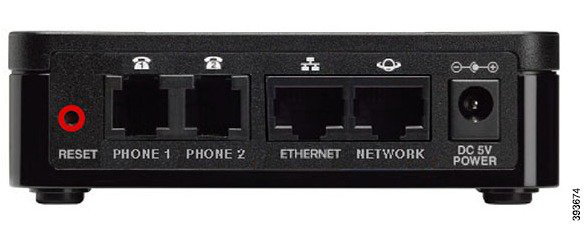
The following figures shows the different ports and buttons found on the back of your ATA.
Cisco ATA 191 and ATA 192 Analog Telephone Adapter Administration Guide for Multiplatform Firmware
3
Get Started
Problem Report Tool Button


Page 12
Figure 3: ATA 191 Back Panel
Figure 4: ATA 192—Back Panel
Table 2: ATA 191 and ATA 192 Back Panel Items
Description
Item
To restart the ATA, use a paper clip or similar object to press this button
briefly.
To restore the factory default settings, press and hold for about 10
seconds.
The LED behaviour for the factory reset:
1.
After you press and hold the button for about 10 seconds, the Power
LED is fast flashing green.
2.
After the factory reset is performed successfully, all LEDs are fast
flashing green for about 5 seconds.
RESET
Use an RJ-11 phone cable to connect an analog phone or fax machine.
PHONE 1
Use an RJ-11 phone cable to connect a second analog phone or fax
machine.
PHONE 2
Use an Ethernet cable to connect your ATA to a device on your network,
such as a computer.
ETHERNET (ATA 192 only)
Use an Ethernet cable to connect to the network.
NETWORK
Use the power adapter that was provided to connect to a power source.
DC 5V POWER
Cisco ATA 191 and ATA 192 Analog Telephone Adapter Administration Guide for Multiplatform Firmware
4
Get Started
ATA 191 and ATA 192 Back Panel

Page 13
Install Your Cisco ATA
You can use either Category 3/5/5e/6 cabling for 10-Mbps connections, but you must use Category 5/5e/6 for
100-Mbps connections.
Procedure
Step 1
Connect the power supply to the Cisco DC Adapter port.
Step 2
Connect a straight-through Ethernet cable from the network to the network port on the ATA. Each ATA ships
with one Ethernet cable in the box.
ATA Voice Quality
The ATA can be custom provisioned within a wide range of configuration parameters. The sections below
describe the factors that contribute to voice quality.
Supported Codecs
The ATA supports the codecs listed below. You can use the default settings or configure the codec settings
in the Audio Configuration section of the Line 1 and Line 2 Settings (PHONE 1 and PHONE 2) page.
Table 3: Supported Codecs
Description
Codec
Very low complexity codecs that support uncompressed 64 kbps digitized voice
transmissions at one through ten 5 ms voice frames per packet. These codecs provide
the highest narrow-band voice quality and uses the most bandwidth of anyof the
available codecs.
G.711 (A-law and
mu-law)
Very low complexity codecs that support uncompressed 64 kbps digitized voice
transmissions at one through ten 5 ms voice frames per packet. These codecs provide
the highest narrow-band voice quality and uses the most bandwidth of anyof the
available codecs.
G.726-32
ITU G.729 voice coding algorithm used to compress digitized speech. G.729a is a
reduced complexity version of G.729 requiring about half the processing power of
G.729. The G.729 and G.729a bit streams are compatible and interoperable, but not
identical.
G.729a
Cisco ATA 191 and ATA 192 Analog Telephone Adapter Administration Guide for Multiplatform Firmware
5
Get Started
Install Your Cisco ATA
Page 14
SIP Proxy Redundancy
An average SIP Proxy Server can handle tens of thousands of subscribers. A backup server allows an active
server to be temporarily switched out for maintenance. The ATA supports the use of backup servers to minimize
or eliminate service disruption.
A simple way to support proxy redundancy is to specify a SIP Proxy Server. The ATA sends a DNS NAPTR
or SRV query to the DNS server. If configured, the DNS server returns SRV records that contain a list of
servers for the domain, with their hostnames, priority, listening ports, and so forth. The ATA tries to contact
the servers in the order of the priority. The server with a lower number has a higher priority. Up to 6 NAPTR
records and 12 SRV records are supported in a query. And an SRV record can associate with up to 10 A
records.
When the ATA fails to communicate with the primary server, the ATA can failover to a lower-priority server.
If configured, the ATA can restore the connection back to the primary. Failover and failback support switches
between servers with different SIP transport protocols. The ATA doesn't perform failback to the primary
server during an active call until the call ends and the failback conditions are met.
Example of Resource Records from the DNS Server
as1bsoft
3600
IN NAPTR 50
50
"s"
"SIPS+D2T"
""
_sips._tcp.tlstest
3600
IN NAPTR 90
50
"s"
"SIP+D2T"
""
_sip._tcp.tcptest
3600
IN NAPTR 100
50
"s"
"SIP+D2U"
""
_sip._udp.udptest
_sips._tcp.tlstest
SRV 1 10 5061 srv1.sipurash.com.
SRV 2 10 5060 srv2.sipurash.com.
_sip._tcp.tcptest
SRV 1 10 5061 srv3.sipurash.com.
SRV 2 10 5060 srv4.sipurash.com.
_sip._udp.udptest
SRV 1 10 5061 srv5.sipurash.com.
SRV 2 10 5060 srv6.sipurash.com.
srv1
3600
IN
A
1.1.1.1
srv2
3600
IN
A
2.2.2.2
srv3
3600
IN
A
3.3.3.3
srv4
3600
IN
A
4.4.4.4
srv5
3600
IN
A
5.5.5.5
srv6
3600
IN
A
6.6.6.6
The following example shows the priority of the servers from the perspective of the ATA.
Priority
IP Address
SIP Protocol
Status
1st
1.1.1.1
TLS
UP
2nd
2.2.2.2
TLS
UP
3rd
3.3.3.3
TCP
UP
4th
4.4.4.4
TCP
UP
5th
5.5.5.5
UDP
UP
6th
6.6.6.6
UDP
UP
The ATA always sends SIP messages to the available address with the top priority and with the status UP in
the list. In the example, the ATA sends all the SIP messages to the address 1.1.1.1. If the address 1.1.1.1 in
the list is marked with the status DOWN, then the ATA communicates with 2.2.2.2 instead. The ATA can
restore the connection back to 1.1.1.1 when the specified failback conditions are met. For more details about
failover and failback, see SIP Proxy Failover, on page 6 and SIP Proxy Fallback, on page 7.
SIP Proxy Failover
The ATA performs a failover in any of these cases:
Cisco ATA 191 and ATA 192 Analog Telephone Adapter Administration Guide for Multiplatform Firmware
6
Get Started
SIP Proxy Redundancy
Page 15
• The ATA sends SIP messages and doesn't get responses from the server.
• The server responds with a code that matches the specified code in Try Backup RSC.
• The ATA gets a TCP disconnection request.
We strongly recommend that you set the Auto Register When Failover to yes when SIP Transport is set
to AUTO.
ATA Failover Behavior
When the ATA fails to communicate with the currently connected server, it refreshes the server list status.
The unavailable server is marked with the status DOWN in the server list. The ATA tries to connect to the
top-priority server with the status UP in the list.
In the following example, the addresses 1.1.1.1 and 2.2.2.2 aren’t available. The ATA sends SIP
messages to 3.3.3.3, which has the top priority among the servers with the status UP.
Priority
IP Address
SIP Protocol
Status
1st
1.1.1.1
TLS
DOWN
2nd
2.2.2.2
TLS
DOWN
3rd
3.3.3.3
TCP
UP
4th
4.4.4.4
TCP
UP
5th
5.5.5.5
UDP
UP
6th
6.6.6.6
UDP
UP
In the following example, there are two SRV records from the DNS NAPTR response. For each SRV
record, there are three A records (IP addresses).
Priority
IP Address
SIP Protocol
Server
Status
1st
1.1.1.1
UDP
SRV1
DOWN
2nd
1.1.1.2
UDP
SRV1
UP
3rd
1.1.1.3
UDP
SRV1
UP
4th
2.2.2.1
TLS
SRV2
UP
5th
2.2.2.2
TLS
SRV2
UP
6th
2.2.2.3
TLS
SRV2
UP
Let's assume that the ATA failed to connect to 1.1.1.1 and then registered to 1.1.1.2. When 1.1.1.2
goes down, ATA behavior depends on the setting of Proxy Fallback Intvl.
• When Proxy Fallback Intvl is set to 0, the ATA tries with the addresses in this order: 1.1.1.1,
1.1.1.3, 2.2.2.1, 2.2.2.2, 2.2.2.3.
• When Proxy Fallback Intvl is set to a value other than zero, the ATA tries with the addresses
in this order: 1.1.1.3, 2.2.2.1, 2.2.2.2, 2.2.2.3.
SIP Proxy Fallback
The proxy fallback requires a value other than zero specified in the Proxy Fallback Intvl field under the
Proxy and Registration section in the ATA administration web page. If you set this field to 0, the SIP proxy
failback feature is disabled.
Cisco ATA 191 and ATA 192 Analog Telephone Adapter Administration Guide for Multiplatform Firmware
7
Get Started
SIP Proxy Fallback
Page 16
The time when the ATA triggers a failback depends on the ATA configuration and the SIP transport protocols
in use.
To enable the ATA to perform failback between different SIP transport protocols, set SIP Transport to
AUTO under the Proxy and Registration section from Voice > Line (n) of the ATA administration web
page.
Failback from a UDP Connection
The failback from a UDP connection is triggered by SIP messages. In the following example, the ATA first
failed to register to 1.1.1.1 (TLS) at the time T1 since there's no response from the server. When SIP Timer
F expires, the ATA registers to 2.2.2.2 (UDP) at the time T2 (T2=T1+SIP Timer F). The current connection
is on 2.2.2.2 via UDP.
Priority
IP Address
SIP Protocol
Status
1st
1.1.1.1
TLS
DOWN
T1 (Down time)
2nd
2.2.2.2
UDP
UP
3rd
3.3.3.3
TCP
UP
The ATA has the following configuration:
<Proxy_Fallback_Intvl_n_ ua="na">60</Proxy_Fallback_Intvl_n_>
<Register_Expires_n_ ua="na">3600</Register_Expires_n_>
<SIP_Timer_F ua="na">16</SIP_Timer_F>
where n is the extension number.
The ATA refreshes the registration at time T2 (T2=(3600-16)*78%). The ATA checks the address list for the
availability of the IP addresses and the down time. If T2-T1 > = 60, the failed server 1.1.1.1 resumes back to
UP and the list is updated to the following. The ATA sends SIP messages to 1.1.1.1.
Priority
IP Address
SIP Protocol
Status
1st
1.1.1.1
TLS
UP
2nd
2.2.2.2
UDP
UP
3rd
3.3.3.3
TCP
UP
Failback from a TCP or TLS Connection
The failback from a TCP or TLS connection is triggered by the parameter Proxy Fallback Intvl. In the
following example, the ATA failed to register to 1.1.1.1 (UDP) at the time T1 and thus registered to 2.2.2.2
(TCP). The current connection is on 2.2.2.2 via TCP.
Priority
IP Address
SIP Protocol
Status
1st
1.1.1.1
UDP
DOWN
T1 (Down time)
2nd
2.2.2.2
TCP
UP
3rd
3.3.3.3
TLS
UP
The ATA has the following configuration:
<Proxy_Fallback_Intvl_n_ ua="na">60</Proxy_Fallback_Intvl_n_>
<Register_Expires_n_ ua="na">3600</Register_Expires_n_>
<SIP_Timer_F ua="na">16</SIP_Timer_F>
where n is the extension number.
The proxy fallback interval (60 seconds) counts down from T1. The ATA triggers proxy failback at the time
of T1+60. If you set the proxy fallback interval to 0 in this example, the ATA keeps the connection on 2.2.2.2.
Cisco ATA 191 and ATA 192 Analog Telephone Adapter Administration Guide for Multiplatform Firmware
8
Get Started
SIP Proxy Fallback
Page 17
Other ATA Voice Quality Features
Silence Suppression and Comfort Noise Generation
Voice Activity Detection (VAD) with Silence Suppression reduces the bandwidth needed for a single call,
making it possible for your network to support more calls overall. VAD distinguishes between speech and
non-speech signals, and Silence Suppression removes the natural silences that occur in a conversation. The
IP bandwidth is used only to transmit speech.
Comfort Noise Generation provides white noise when nobody is talking so you know that your call is still
connected.
Modem and Fax Pass-Through
The following applies to modem and fax pass-through:
• Modem pass-through mode can be triggered by predialing the Vertical Service Activation Code for the
Modem Line Toggle Code. You can configure this setting in the Vertical Service Activation Codes
section of the Regional page.
• A CED/CNG tone or an NSE event triggers FAX pass-through mode.
• Echo canceller is automatically disabled for Modem passthrough mode.
• Echo canceller is disabled for FAX pass-through if FAX Disable ECAN (Line 1 or 2 tab) is set to “Yes”
for that line. In this case, FAX pass-through is the same as Modem pass-through.
• Call waiting and silence suppression are automatically disabled for both FAX and Modem pass-through.
Out-of-band DTMF transmission is disabled during modem or fax passthrough.
Adaptive Jitter Buffer
The ATA can buffer incoming voice packets to minimize the impact of variable network delays. This process
is known as jitter buffering. The size of the jitter buffer adjusts to changing network conditions. The ATA
has a Network Jitter Level control setting for each line of service. The jitter level determines how aggressively
the ATA tries to shrink the jitter buffer over time to achieve a lower overall delay. If the jitter level is higher,
it shrinks more gradually. If jitter level is lower, it shrinks more quickly. You can use the default settings or
configure this feature in the Network Settings section of the "Voice Settings Configuration" chapter.
Adjustable Audio Frames Per Packet
This feature allows you to set the number of audio frames contained in one RTP packet. Packets can be adjusted
to contain from 1 to 10 audio frames. Increasing the number of packets decreases the bandwidth utilized, but
it also increases delay and may affect voice quality. You can configure this setting in the RTP Parameters
section of the SIP page.
DTMF Relay
The ATA may relay DTMF digits as out-of-band events to preserve the fidelity of the digits. This action
enhances the reliability of DTMF transmission required by many IVR applications such as dial-up banking
and airline information. You can configure this setting in the RTP Parameters section of the SIP page.
Cisco ATA 191 and ATA 192 Analog Telephone Adapter Administration Guide for Multiplatform Firmware
9
Get Started
Other ATA Voice Quality Features
Page 18
Call Progress Tones
The ATA has configurable call progress tones. Call progress tones are generated locally on the ATA and alert
you to a call's status. Parameters for each type of tone, such as a dial tone, may include frequency and amplitude
of each component, and cadence information. You can keep the default settings or configure these tones in
the Call Progress Tones section of the Regional page.
Call Progress Tone Pass Through
This feature allows you to hear the call progress tones (such as ringing) that are generated from the far-end
network.
Echo Cancellation
Impedance mismatch between the phone and the IP Telephony gateway phone port can lead to near-end echo.
The ATA has a near-end echo canceller that compensates for impedance mismatch. The ATA also implements
an echo suppressor with Comfort Noise Generator (CNG) so that any residual echo is not noticeable. This
feature is enabled by default. You can configure this setting in the Audio Configuration of the Line 1 and
Line 2 Settings (PHONE 1 and PHONE 2) page.
Hook Flash Events
The ATA signals hook flash events to the proxy during a connected call. This feature can be used to provide
advanced mid-call services with third-party-call control.
• Depending on your service provider, you may need to disable Call Waiting Service, Three Way Conference
Service, or Three Way Call Service. These three features could prevent the signaling of a hook flash
event to the softswitch. You can configure these settings in the Supplementary Service Subscription
section of the Line 1 and Line 2 Settings (PHONE 1 and PHONE 2) page.
• The Hook Flash setting determines the time period required for hook flash detection. It is in the Control
Timer Values section of the SIP page.
Configurable Dial Plan with Interdigit Timers
The ATA has three configurable interdigit timers:
• The initial timeout—signals that a phone is taken off hook.
• A long timeout—signals the end of a dialed string.
• A short timeout—signals that more digits are expected.
Polarity Control
The ATA allows the polarity to be set when a call is connected and when a call is disconnected. This feature
is required to support some pay phone system and answering machines. You can configure these settings in
the FXS Port Polarity Configuration section of the Line 1 and Line 2 Settings (PHONE 1 and PHONE 2)
page.
Cisco ATA 191 and ATA 192 Analog Telephone Adapter Administration Guide for Multiplatform Firmware
10
Get Started
Other ATA Voice Quality Features
Page 19
Calling Party Control
Calling Party Control (CPC) momentarily removes the voltage between the tip and the ring signals, signaling
that the calling party has hung up. This feature is useful for auto-answer equipment. You can configure these
settings in the Control Timer Values section of the Regional page.
Encryption of SIP Messages using SIP over TLS
You can enable SIP over Transport Layer Security (TLS) to encrypt the SIP messages between the service
provider and your business. SIP over TLS relies on the TLS protocol to encrypt the signaling messages. You
can configure the SIP Transport parameter in the SIP Settings section of the Line 1 and Line 2 Settings
(PHONE 1 and PHONE 2) page.
Secure Calling Using SRTP
Voice packets are encrypted by using Secure Real-Time Transport Protocol (SRTP). This function is
implemented on a standards basis (RFC4568). Secure call service (Secure Call Serv) is enabled by default. It
is located in the Supplementary Service Subscription section of the Line 1 and Line 2 Settings (PHONE 1
and PHONE 2) page. When this service is enabled, you can activate secure calling by pressing the star (*)
key before dialing a phone number. You can also enable the Secure Call Setting to encrypt all calls from a
phone.
DNS NAPTR Support
The Line 1 and Line 2 (PHONE 1 and PHONE2) can select the SIP transport protocol (TPC, UDP, or TLS)
automatically based on the Name Authority Pointer (NAPTR) records on the DNS server. Typically, the line
uses the protocol with the highest priority in the records.
Cisco ATA 191 and ATA 192 Analog Telephone Adapter Administration Guide for Multiplatform Firmware
11
Get Started
Other ATA Voice Quality Features
Page 20
Cisco ATA 191 and ATA 192 Analog Telephone Adapter Administration Guide for Multiplatform Firmware
12
Get Started
Other ATA Voice Quality Features
Page 21
C H A P T E R 2
New and Changed Information
• New and Changed for Firmware Release 11.3(1), on page 13
• New and Changed for Firmware Release 11.2(5), on page 14
• New and Changed for Firmware Release 11.2(4), on page 14
• New and Changed for Firmware Release 11.2(3), on page 15
• New and Changed for Firmware Release 11.2(2), on page 15
• New and Changed for Firmware Release 11.2(1), on page 15
New and Changed for Firmware Release 11.3(1)
New and Changed
Revision
Security Settings, on page 43
Updated the topic to add the new option of "TLS Min
Version"
Access the Phone Web Interface, on page 19
Updated the topic for the feature "Password Changing
Required"
Change Password after an Initial Registration or a
Factory Reset, on page 20
Added the task for the feature "Password Changing
Required"
SIP Settings, on page 80
Updated the topic to add new parameters "MediaSec
Request" and "MediaSec over TLS Only".
Proxy and Registration, on page 87
Updated the topic to add the new parameters
"Survivability Proxy" and "Survivability Proxy
Fallback Intvl".
Miscellaneous Settings, on page 42
Update the topic to add the new parameter
"Survivability Test Mode".
MIC Cert Refresh Status, on page 39
MIC Cert Settings, on page 59
Added the new topics for the feature "MIC Certificate
Renewal by SUDI Service".
HTTP Proxy (ATA 191 and 192), on page 34
Update the topic for the feature "MIC Certificate
Renewal by SUDI Service".
Cisco ATA 191 and ATA 192 Analog Telephone Adapter Administration Guide for Multiplatform Firmware
13

Page 22
New and Changed for Firmware Release 11.2(5)
New and Changed
Revision
Security Settings, on page 43
New topic for the feature FIPS mode
ATA 191 and ATA 192 Top Panel, on page 2
Update the topic to add FIPS relevant information
SNMPv3 Settings, on page 109
Updated the parameter description of "Auth-Protocol"
and "PrivProtocol"
SIP Settings, on page 80
Updated the topic to add the new parameter "Auto
Support RFC8760"
Security Settings, on page 43
Updated the topic to add the new parameter "TLS Min
Version" and the new table "TLS Minimum Version
Results"
Audio Configuration, on page 94
Updated the topic to add the new parameter
"Encryption Method"
Subscriber Information, on page 90
Updated the topic to add the new parameter "Reserved
Auth Realm"
New and Changed for Firmware Release 11.2(4)
New and Changed
Revision
Audio Configuration, on page 94
Updated the FAX Enable T38 parameter for the feature
Outbound Fax Refinement
NAT Settings, on page 78
Updated the topics for the feature OPTIONS Support
in NAT Keep Alive Messages
Crash Dump, on page 115
Added the missing topic for the feature Log
Management for Users
Access the Phone Web Interface, on page 19
Cisco ATA 192 Web Access Fields, on page 106
Cisco ATA 191 Web Access Fields, on page 105
Cisco ATA 192 Remote Access Fields, on page 106
Troubleshoot Your Fax, on page 136
Updated the topics for the feature Default Web Access
Protocol Changes to HTTPS
SIP Proxy Redundancy, on page 6
Updated the topics for the feature Increased Maximum
Number of A Records for SRV Record
Cisco ATA 191 and ATA 192 Analog Telephone Adapter Administration Guide for Multiplatform Firmware
14
New and Changed Information
New and Changed for Firmware Release 11.2(5)
Page 23
New and Changed for Firmware Release 11.2(3)
New and Changed
Revision
HTTP Proxy (ATA 191 and 192), on page 34
Added the topic for the HTTP Proxy Support feature
Control Timer Values (Sec), on page 67
Miscellaneous, on page 75
Updated the topics to add the value range of the
parameters Call Back Delay, VMWI Refresh Intvl,
DTMF Playback Length, DTMF Playback Level, and
DTMF Twist
New and Changed for Firmware Release 11.2(2)
New and Changed
Revision
SIP Settings, on page 80
Updated the parameter SIP Transport
Other ATA Voice Quality Features, on page 9
Updated the topic to add the new feature DNS NAPTR
Support
SIP Proxy Redundancy, on page 6
Updated the topic to add more examples
SIP Proxy Failover, on page 6
SIP Proxy Fallback, on page 7
Added the topic for the SIP proxy redundancy feature
Proxy and Registration, on page 87
Updated the topic to add the parameter Auto
Register When Failover
SIP Proxy Redundancy, on page 6
Updated the topic to mention the maximum number
of NAPTR records and SRV records supported in a
query
Set up a Secure Line, on page 84
Added a new task topic on how to secure a line by
automatic SRTP/RTP selection
Call Feature Settings, on page 85
Updated the Call Feature Settings table with a new
parameter Secure Call Option
New and Changed for Firmware Release 11.2(1)
New and Changed
Revision
Debug Log Module, on page 111
Updated the navigation path
Cisco ATA 191 and ATA 192 Analog Telephone Adapter Administration Guide for Multiplatform Firmware
15
New and Changed Information
New and Changed for Firmware Release 11.2(3)
Page 24
New and Changed
Revision
Emergency Calls, on page 143
Emergency Call Support Background, on page 143
Emergency Call Support Terminology, on page 143
Configure the ATA to Make Emergency Calls, on
page 144
E911 Geolocation Configuration, on page 86
Added the topics for the E911 feature
RTP Parameters, on page 49
Updated RTP Parameters table to add the Call
Statistics parameter
Call Statistics are Not Available in the Server, on page
128
Added a topic for the reporting End-of-Call Statistics
feature
Generate a Problem Report Remotely, on page 114
Added a task for the remote PRT generation feature
PRT Viewer, on page 113
Updated the topic for the remote PRT generation
feature
ATA with Firmware Release 11.1.0MSR3-9 and Older
Doesn't Upgrade, on page 117
Added a topic how to address the issue when ATA
11.1.0MSR3-9 and older doesn't upgrade
Cisco ATA 191 and ATA 192 Analog Telephone Adapter Administration Guide for Multiplatform Firmware
16
New and Changed Information
New and Changed for Firmware Release 11.2(1)
Page 25
C H A P T E R 3
Quick Setup for Voice over IP Service
• Set Up Voice over IP, on page 17
Set Up Voice over IP
The Quick Setup page displays when you log in to the ATA web page for the first time. Use this page to
connect your phone to your provider’s Voice over IP network.
You need an Internet connection to link with your service provider’s network. With the default network
settings, your ATA has Internet connectivity, if the WAN port connects to a port on your router.
Note
Procedure
Step 1
For Line 1 and Line 2, enter the settings for the phone services used by the phones or fax connected to the
PHONE1 and PHONE2 ports.
• Proxy: Enter the IP address of the service provider’s proxy server.
• Display Name: Enter the name or DN that you want to use to identify your account. This name typically
is used as your Caller ID name.
• User ID: Enter the user ID that is required to log in to your Internet account.
• Password: Enter the password that is required to log in to your Internet account.
• Dial Plan in (Line section only): Keep the default settings (recommended) or edit the dial plan to suit
your site.
Step 2
Click Submit to save your settings. The voice service restarts.
Step 3
To verify your progress, perform the following tasks:
a)
Check if phone LED is a steady green, indicating that the phone has registered.
If the line is not registered, refresh the browser several times because it can take a few seconds for the
registration to complete. Also verify that your Internet Settings, including DNS server settings, are
configured according to the information from your ISP.
Cisco ATA 191 and ATA 192 Analog Telephone Adapter Administration Guide for Multiplatform Firmware
17


Page 26
b) Use an external phone to call the phone number assigned to you by your ISP. Verify that the phone rings
and you have two-way audio on the call.
Cisco ATA 191 and ATA 192 Analog Telephone Adapter Administration Guide for Multiplatform Firmware
18
Quick Setup for Voice over IP Service
Set Up Voice over IP
Page 27
C H A P T E R 4
Network Configuration
• Web-Based Configuration Utility, on page 19
• Basic Setup, on page 21
• Advanced Settings, on page 28
• Application, on page 31
Web-Based Configuration Utility
Your phone system administrator can allow you to view the phone statistics and modify some or all the
parameters. This section describes the features of the phone that you can modify with the phone web user
interface.
Access the Phone Web Interface
If your service provider has disabled access to the configuration utility, contact the service provider before
proceeding.
Procedure
Step 1
Ensure that the computer can communicate with the phone. No VPN in use.
Step 2
Start a web browser.
Step 3
Enter the IP address of the phone in your web browser address bar.
• User or Admin Access: https://<ip address>:<port>/, and then enter the username and
password.
If you use the default user credentials to access the configuration utility, you will be prompted to change
the password. For details, see Change Password after an Initial Registration or a Factory Reset, on page
20.
For example, https://10.64.84.147/
Cisco ATA 191 and ATA 192 Analog Telephone Adapter Administration Guide for Multiplatform Firmware
19

Page 28
Allow Web Access to the ATA
To view the ATA parameters, enable the configuration profile. To make changes to any of the parameters,
you must be able to change the configuration profile. Your system administrator might have disabled the
option to make the ATA web user interface viewable or writable.
For more information, see the Cisco ATA 191 and 192 Multiplatform Firmware Provisioning Guide
Before you begin
Access the phone administration web page. See Access the Phone Web Interface, on page 19.
Procedure
Step 1
Click System.
Step 2
In the System Configuration section, set Enable Web Server to Yes.
Step 3
To update the configuration profile, click Submit All Changes after you modify the fields in the phone web
user interface.
The phone reboots and the changes are applied.
Step 4
To clear all changes that you made during the current session (or after you last clicked Submit All Changes),
click Undo All Changes. Values return to their previous settings.
Change Password after an Initial Registration or a Factory Reset
For security purposes, you must change the password when you access the Phone Adapter Configuration
Utility with the default username and password. The configuration utility will be available after you change
the password.
The password change is required after your ATA's initial registration or you perform a factory reset on your
ATA. In addition, this is applicable for both user and administrator accounts.
Before you begin
You access the configuration utility with the default username and password.
Procedure
Step 1
On the Change Password page, enter the username and password, as described below.
• Username—Enter a username.
• Old Password—Enter the existing password.
• New Password—Enter your new password. The password must contain at least 8 to 127 characters.
• Confirm New Password—Enter the new password again, to confirm.
Cisco ATA 191 and ATA 192 Analog Telephone Adapter Administration Guide for Multiplatform Firmware
20
Network Configuration
Allow Web Access to the ATA
Page 29
Step 2
After making changes, click Submit to save your settings, or click Cancel to cancel the settings.
Basic Setup
Use the Network Setup > Basic Setup pages to configure your Internet connection, local network settings
(ATA 192 only), and your time settings.
Network Service (ATA 192 Only)
Use the Network Setup > Basic Setup > Network Service page to configure the operating mode of the ATA
192.
After making changes, click Submit to save your settings, or click Cancel to redisplay the page with the
saved settings.
You can configure the ATA to operate in one of the following modes:
• NAT: Network Address Translation (NAT) allows multiple devices on a private network to share a
public, routable IP address. In order for theVoice over IP service to co-exist with NAT, some form of
NAT traversal is required either on the ATA or another network device. Use this option if your ATA
connects to one network on the WAN port and to another network on the LAN port. This option is selected
by default and is suitable for most deployments.
• Bridge: Bridged mode is used if the ATA is acting as a bridge device to another router. Choose this
option if your ATA bridges a network to its LAN port (with connected devices also in the 10.0.0x range).
• Monitor Network Drop on Internet Port Only: This parameter is used for how to report the link state
when both Ethernet(LAN) and Network(WAN) ports are connected.
• Off: If you unplug and plug the WAN cable, meanwhile the LAN port state is still UP, then the
ATA doesn't perform any operation.
• On: If you unplug and then plug the WAN cable, then the ATA triggers a warm reboot even though
the LAN port state is still UP. In this case, the ATA will try to register again.
• The parameter takes effect only when you select the Bridge mode.
• The parameter doesn't take effect when only the WAN port is connected.
Note
Basic Settings
Use the Network Setup > Basic Settings page to set up your basic network settings.
Cisco ATA 191 and ATA 192 Analog Telephone Adapter Administration Guide for Multiplatform Firmware
21
Network Configuration
Basic Setup

Page 30
Table 4: Basic Settings
Description
Field
The domain name, if specified by your ISP.
Otherwise, leave the field blank.
Domain Name
The name of the ATA. The default value is the model
number. Your ISP may specify a host name to use.
Host Name
Choose the stack mode for network; there are three
modes can be set: IPv4 only, Pv6 Only, or Dual.
Stack mode
Choose the SIP packet preference, either IPv4 or IPv6.
Signaling Preference
Choose the RTP packet preference, either is IPv4 or
IPv6.
Media Preference
IPv4 Settings
Use the Network Setup > Basic Setup > IPv4 Settings page to set up your IPv4 connection.
Enter the settings as described in the table. After making changes, click Submit to save your settings, or click
Cancel to redisplay the page with the saved settings.
Table 5: Internet Connection Type
Description
Field
Specify the Internet addressing method that your ISP requires. Default setting: Automatic
Configuration - DHCP
• Automatic Configuration - DHCP: Use this setting if your ISP dynamically provides
an IP address. No additional settings are required on this page.
• Static IP: Use this setting if your ISP assigned a static IP address. Complete the fields
that appear.
• PPPoE (DSL service): Some DSL-based ISPs use PPPoE (Point-to-Point Protocol
over Ethernet) to establish Internet connections. If you are connected to the Internet
through a DSL line, check with your ISP to see if they use PPPoE. Complete the fields
that appear.
Connection
Type
• Internet IP Address and Subnet Mask: Enter the IP address and subnet mask that
was assigned to your account by your service provider. This address is seen by external
users on the Internet.
• Default Gateway: Enter the Gateway IP Address that was provided by your ISP.
If needed, you can adjust the MTU and Optional Settings.
Static IP
Settings
Cisco ATA 191 and ATA 192 Analog Telephone Adapter Administration Guide for Multiplatform Firmware
22
Network Configuration
IPv4 Settings
Page 31
Description
Field
• User Name and Password: Enter the user name and password that you use to log in
to your ISP network through a PPPoE connection.
• Service Name: If provided by your ISP, enter the Service Name.
• Connect on Demand: You can configure the ATA to disconnect your Internet
connection after a specified period of inactivity (Max Idle Time). If your Internet
connection has timed out, this feature also enables the ATA to re-establish your
connection when you attempt to access the Internet again. If you choose this option,
also set the Max Idle Time.
• Keep Alive: This option keeps you connected to the Internet indefinitely, even when
your connection sits idle. If you choose this option, also set the Redial Period, which
is the interval at which the ATA verified Internet connectivity. The default period is 30
seconds.
If needed, you can adjust the MTU and Optional Settings.
PPPoE
Settings
The Maximum Transmission Unit (MTU) setting specifies the largest protocol data unit (in
bytes) permitted for network transmission. Generally, a larger MTU means greater efficiency.
However, a larger packet may cause delays for other traffic and is more likely to become
corrupted. Usually, you keep the default setting to allow the ATA to choose the appropriate
MTU. To specify the MTU, select Manual, and then enter the number of bytes.
MTU
Table 6: Optional Settings
Description
Field
Choose the preferred method for choosing a DNS server.
• DHCP-Manual—The DNS server settings from the network server takes precedence,
and your entries in the DNS fields are used only as a backup.
• Manual-DHCP—Your entries in the DNS fields take precedence, and the DNS
server settings from the network server are used as a backup.
• Manual—Your entries in the DNS fields are used to choose a DNS server.
DNS Server
Order
Set the Primary DNS for IPv4.
Primary DNS
Set the Secondary DNS for IPv4.
Secondary DNS
IPv6 Settings
Use the Network Setup > Basic Setup > IPv6 Settings page to set up your IPv6 connection.
Enter the settings as described in the table. After making changes, click Submit to save your settings, or click
Cancel to redisplay the page with the saved settings.
Cisco ATA 191 and ATA 192 Analog Telephone Adapter Administration Guide for Multiplatform Firmware
23
Network Configuration
IPv6 Settings
Page 32
Table 7: IPv6 Settings
Description
Field
Specify the Internet addressing method that your ISP requires. Default setting: Automatic
Configuration - DHCP
Automatic Configuration - DHCP: Use this setting if your ISP dynamically provides an IP
address. No additional settings are required on this page.
Static IP: Use this setting if your ISP assigned a static IP address. Complete the following
fields:
• Internet IPv6 Address and Prefix Length—Enter the IPv6 address and prefix length that
was assigned to your account by your service provider. The public sees this address.
• Default Gateway—Enter the Gateway IPv6 Address that was provided by your ISP.
PPPoE (DSL service): Some DSL-based ISPs use PPPoE (Point-to-Point Protocol over Ethernet)
to establish Internet connections. If you are connected to the Internet through a DSL line, check
with your ISP to see if they use PPPoE. Complete the following fields:
• User Name and Password—Enter the username and password that you use to log in to
your ISP network through a PPPoE connection.
• Service Name—If provided by your ISP, enter the Service Name.
• Connect on Demand—You can configure the ATA to disconnect your Internet connection
after a specified period of inactivity (Max Idle Time). If your Internet connection has
timed out, this feature enables the ATA to automatically reconnect when you try to access
the Internet again. If you choose this option, also set the Max Idle Time.
• Keep Alive—This option keeps you connected to the Internet indefinitely, even when
your connection sits idle. If you choose this option, also set the Redial Period, which is
the interval at which the ATA verified Internet connectivity. The default period is 30
seconds.
Internet
Connection
Type
Table 8: Optional Settings
Description
Field
Choose the preferred method for choosing a DNS server.
• DHCP-Manual—The DNS server settings from the network server takes
precedence, and your entries in the DNS fields are used only as a backup.
• Manual-DHCP—Your entries in the DNS fields take precedence, and the
DNS server settings from the network server are used as a backup.
• Manual—Your entries in the DNS fields are used to choose a DNS server.
DNS Server Order
Enable if you want to allow Auto Configuration.
Allow Auto
Configuration.
Set the Primary DNS for IPv6.
Primary DNS
Cisco ATA 191 and ATA 192 Analog Telephone Adapter Administration Guide for Multiplatform Firmware
24
Network Configuration
IPv6 Settings
Page 33
Description
Field
Set the Secondary DNS for IPv6.
Secondary DNS
IPv4 LAN Settings (ATA 192 Only)
Use the Network Setup > Basic Setup > IPv4 LAN Settings page to set the IP address and subnet mask for
your local network. Also configure the settings for the built-in DHCP server (ATA 192 only).
After making changes, click Submit to save your settings, or click Cancel to redisplay the page with the
saved settings.
Router IP
Enter the Local IP Address and Subnet Mask for your local network. The default setting is 192.168.15.1
with a subnet mask of 255.255.255.0.
DHCP Server Setting
Description
Field
The ATA can use the built-in DHCP server to dynamically assign IP addresses to
connected devices. Click Enabled to enable the DHCP server, or clickDisabled to disable
this feature.
Default setting: Enable
DHCP Server
Click the Show DHCP Reservation button to view and manage the DHCP client list.
Click the Hide DHCP Reservation button to hide the list. When the list is displayed, you
can perform the following tasks:
• To reserve a static IP address for a current DHCP client: Check the box for the client
in the Select Clients from DHCP Tables list. ClickAdd Clients. The selected
clients are added to the Clients Already Reserved list. These clients have static IP
addresses that do not change.
• To add a client that isn't in the Select Clients from DHCP Tables list: Type a name
for the client in the Enter Client Name box. Enter an IP address for this client in
the Assign IP Address box. Enter the MAC address in the following
format:00:00:00:00:00:00. Click Add.
• To remove a client from the Clients Already Reserved list: Check the box for the
client. Click Remove.
IP Reservation
Enter the IP address of the default gateway to be used by the DHCP clients.
Default setting: 192.168.15.1 (the IP address of the ETHERNET (LAN) interface)
Default Gateway
Enter the first address in the range of addresses assigned dynamically by the DHCP
server.
Default setting: 192.168.15.100
Starting IP
Address
Cisco ATA 191 and ATA 192 Analog Telephone Adapter Administration Guide for Multiplatform Firmware
25
Network Configuration
IPv4 LAN Settings (ATA 192 Only)
Page 34
Description
Field
Enter the maximum number of devices that can dynamically receive, or “lease,” DHCP
addresses from the DHCP server.
Default setting: 50
IMPORTANT: Typically, the ATA can support up to five connected computers for
business-related tasks such as web browsing and viewing email. The ATA is not designed
to support streaming music, video, games, or other network traffic-intensive tasks.
Maximum DHCP
Users
Enter the number of minutes that a dynamically assigned IP address can be in use, or
“leased.” After this time elapses, a client device has to request a DHCP lease renewal.
Use 0 to represent 1 day, 9999 never expire.
Default setting: 0
Client Lease Time
Provides provisioning server address information to hosts that request this option. Server
information can be defined in one of three ways:
• None: The ATA uses its own TFTP server to source provisioning files, so it returns
its own local IP address to the client.
• Remote TFTP Server: The ATA was configured by using this method, and received
server information through Option 66 on its WAN interface. In response to client
requests, it provides the remote TFTP server information.
• Manual TFTP Server: Allows the manual configuration of a configuration server
address. This option is used to provide either an IP address or a fully qualified
hostname. But the ATA also accepts and offers a full URL including protocol, path,
and filename to meet the requirements of specific clients.
Default setting: None
Option 66
If you chose Manual TFTP Server for Option 66, enter the IP address, hostname, or URL
of the TFTP server.
Default setting: blank
TFTP Server
Provides a configuration or bootstrap filename to hosts that request this option. This
option is used with option 66 to allow a client to form an appropriate TFTP request for
the file.
Default setting: blank
Option 67
Provides a configuration URL to clients that request this option. An option 159 URL
defines the protocol and path information by using an IP address for clients that cannot
use DNS. For example: https://10.1.1.1:888/configs/bootstrap.cfg
Default setting: blank
Option 159
Provides a configuration URL to clients that request this option. An option 160 URL
defines the protocol and path information by using a fully qualified domain name for
clients that can use DNS. For example:
https://myconfigs.cisco.com:888/configs/bootstrap.cfg
Default setting: blank
Option 160
Cisco ATA 191 and ATA 192 Analog Telephone Adapter Administration Guide for Multiplatform Firmware
26
Network Configuration
IPv4 LAN Settings (ATA 192 Only)
Page 35
Description
Field
When enabled, the DNS proxy relays DNS requests to the current public network DNS
server. It also replies as a DNS resolver to the client device on the network. Click Enabled
to enable this feature, or clickDisabled to disable it. If DNS proxy is disabled, then DHCP
clients are offered DNS server information by using the Static DNS servers or by using
the servers specified for the INTERNET (WAN) interface.
DNS Proxy
IPv6 LAN Setting (ATA 192 Only)
Use the Network Setup > Basic Setup > IPv6 LAN Settings page to set up your IPv6 LAN connection.
Enter the settings as described in the table. After making changes, click Submit to save your settings, or click
Cancel to redisplay the page with the saved settings.
Table 9: Internet Connection Type
Description
Field
Click Enabled to enable the DHCP server, or click Disabled to disable this feature.
Default setting: Enable
DHCP Server
Choose the address assign type: SLAAC/DHCPv6.
Address Assign
Type
Choose whether to support DHCPv6 delegation, if Yes, user can’t configure IPv6
Address Prefix.
DHCPv6 Delegation
Set the IPv6 address prefix for IPv6 LAN interface, the Prefix Length is fixed to 64.
IPv6 Address Prefix
Set the IPv6 address prefix length for IPv6 LAN interface.
Range:1-112
IPv6 Address
Length
Set the IPv6 Static DNS.
IPv6 Static DNS
Display the LAN IPv6 address information.
LAN IPv6 Address
Time Settings
Use the Network Setup > Basic Setup > Time Settings page to set the system time for the ATA. By default,
the system time is set automatically by using a Network Time Protocol (NTP) server. You can configure the
system time manually. In addition, you can use this page to specify your time zone, enable Daylight Saving
adjustments, and modify related settings.
After making changes, click Submit to save your settings, or click Cancel to redisplay the page with the
saved settings.
If the ATA doesn't receive the response from the NTP server, then the system time for the ATA uses the build
date and time of the firmware.
Note
Cisco ATA 191 and ATA 192 Analog Telephone Adapter Administration Guide for Multiplatform Firmware
27
Network Configuration
IPv6 LAN Setting (ATA 192 Only)

Page 36
User Manual
If you prefer to set the system manually, click User Manual and then enter the date and time.
Table 10: Time Settings
Description
Field
Enter the date in the following order: four-digit year, month, day.
Date
Enter the time in the following order: hour (from 1 to 24), minutes, and seconds.
Time
Time Zone
To use a time server to establish the time settings, select Time Zone. Then complete the fields in this section.
Table 11: Time Zone Settings
Description
Field
Choose the time zone for the site where the ATA is in operation. Default
setting: (GMT-08:00) Pacific Time (USA & Canada).
Time Zone.
Check the box if you want to automatically adjust the time when Daylight
Savings Time is in effect. Otherwise, uncheck the box.
Adjust Clock for Daylight
Saving Changes.
To use the ATA’s default Network Time Protocol (NTP) server, select Auto
from the drop-down list. If you want to specify the NTP server, select Manual,
and then enter the NTP server address.
Default setting: Auto
Time Server Address.
Enter the Resync timer interval value (in seconds). This timer controls how
often the ATA resynchronizes with the NTP server.
Default setting: 3600 seconds
Resync Timer
Choose this option to allow the ATA to automatically reconnect to the time
server after a system reboot.
Default setting: Disabled
Auto Recovery After Reboot
Advanced Settings
Use the Network Setup > Advanced Settings pages to configure features including port flow control, MAC
address cloning, VPN passthrough, and VLAN.
Port Setting (ATA 192 Only)
Use the Network Setup > Advanced Settings > Port Setting page to set the ETHERNET (LAN) port
attributes.
Cisco ATA 191 and ATA 192 Analog Telephone Adapter Administration Guide for Multiplatform Firmware
28
Network Configuration
Advanced Settings
Page 37
After making changes, click Submit to save your settings, or click Cancel to redisplay the page with the
saved settings.
Table 12: Port Settings
Description
Field
Flow control is a mechanism that temporarily stops the transmission of data on a port. For
example, a device is transmitting data faster than some other part of the network can accept
it. The overwhelmed network element halts the transmission of the sender for a specified time.
Choose Enabled to enable this feature, or choose Disabled to disable this feature.
Default setting: Enabled
Flow
Control
Choose the duplex mode. You can select from Auto-negotiate, 10 Half, 10 Full, 100 Half and
100 Full. Cisco recommends that choosing Auto-negotiate to automatically select the
appropriate mode for the traffic. Use caution with other settings. Problems can result if you
choose a setting that is not appropriate for the network devices.
Default setting: Auto-negotiate
Speed
Duplex
MAC Address Clone
A MAC address is a 12-digit code assigned to a unique piece of hardware for identification purposes. Some
ISPs require that you register a MAC address in order to access the Internet. If you previously registered your
account with another MAC address, it may be convenient to assign that MAC address to your ATA. You can
use the Network Setup > Advanced Settings > MAC Address Clone page to assign a MAC address that
you previously registered with your Service Provider.
After making changes, click Submit to save your settings, or click Cancel to redisplay the page with the saved
settings.
Table 13: MAC Address Clone Settings
Description
Field
Click Enabled to enable MAC address cloning, or click Disabled to disable this feature.
Default setting: Disabled.
MAC Clone
Enter the MAC address that you want to assign to your ATA. If your computer’s MAC address
is the address that you previously registered for your ISP account, click Clone Your PC’s
MAC. Your computer’s MAC address appears in the MAC Address field.
Default setting: the current MAC address of your ATA
MAC
Address
VPN Passthrough (ATA 192 Only)
Use the Network Setup > Advanced Settings > VPN Passthrough page to configure VPN passthrough for
IPsec, PPTP, and L2TP protocols. Use this feature if there are devices behind the ATA that require an
independent IPsec tunnel. For example, a device may need to use a VPN tunnel to connect to another router
on the WAN.
Cisco ATA 191 and ATA 192 Analog Telephone Adapter Administration Guide for Multiplatform Firmware
29
Network Configuration
MAC Address Clone
Page 38
By default, VPN Passthrough is enabled for IPsec, PPTP, and L2TP.
After making changes, click Submit to save your settings, or click Cancel to redisplay the page with the saved
settings.
Table 14: VPN Passthrough Settings
Description
Field
Internet Protocol Security (IPsec) is a suite of protocols used to implement secure exchange
of packets at the IP layer. Click Enabled to enable this feature, or click Disabled to disable
it.
Default setting: Enabled
IPsec
Passthrough
Point-to-Point Tunneling Protocol (PPTP) allows the Point-to-Point Protocol (PPP) to be
tunneled through an IP network. To disable PPTP Passthrough, select Disabled.
Default setting: Enabled
PPTP
Passthrough
Layer 2 Tunneling Protocol is the method used to enable Point-to-Point sessions using
the Internet on the Layer 2 level. Click Enabled to enable this feature, or click Disabled
to disable it.
Default setting: Enabled
L2TP
Passthrough
VLAN
Use the Network Setup > Advanced Settings > VLAN page to assign a VLAN ID to your network. For
example, your call control system may require a particular voice VLAN ID.
After making changes, click Submit to save your settings, or click Cancel to redisplay the page with the saved
settings.
Table 15: VLAN Settings
Description
Field
Click Enabled to enable a VLAN, or click Disabled to disable this feature.
Default setting: Disabled
Enable
VLAN.
The VLAN ID can be any numeral from 1 to 4094. When VLAN is enabled, the default
setting is 1.
VLAN ID
CDP and LLDP
Device discovery protocols enable directly connected devices to discover information about each other. You
may wish to enable these protocols to allow your network management system to learn about your ATA and
endpoints. Use the Network Setup > Advanced Settings > CDP & LLDP page to specify the settings for
Cisco Discovery Protocol (CDP) and the Link Layer Discovery Protocol (LLDP). When enabled, the ATA
sends messages to a multicast address and listens to the messages sent by other devices using the protocol.
Cisco ATA 191 and ATA 192 Analog Telephone Adapter Administration Guide for Multiplatform Firmware
30
Network Configuration
VLAN
Page 39
After making changes, click Submit to save your settings, or click Cancel to redisplay the page with the
saved settings.
Application
Use the Network Setup > Application pages to support voice service and any servers that you host for public
access.
Quality of Service (QoS) (ATA 192 Only)
Use the Network Setup > Application > QoS page to set the upstream bandwidth to suit your broadband
service. This feature is enabled by default and helps to ensure that voice is prioritized during periods of heavy
network traffic.
After making changes, click Submit to save your settings, or click Cancel to redisplay the page with the
saved settings.
Table 16: QoS Settings
Description
Field
Click Always On to enable QoS settings always, or click On When Phone In Use to
enable it only when there is voice traffic.
Default setting: On When Phone In Use
QoS Policy
Enter the maximum available upstream bandwidth value specified by your Internet
Service Provider.
Default setting: 100000 kbps
Important: Do not overstate the upstream bandwidth that you receive from your service
provider. Setting this value higher than the available service bandwidth can result in
traffic being dropped arbitrarily in the service provider's network.
Upstream
Bandwidth
Port Forwarding (ATA 192 Only)
Use the Network Setup > Application > Port Forwarding page if you require access to specific ports from
external devices.
List of Port Forwarding
To add a port forwarding rule, click Add Entry. To edit a port forwarding rule, select it in the list and then
click the pencil icon. To remove a port forwarding rule, click the delete icon.
Table 17: Port Forwarding Settings
Description
Field
An identification number for the port forwarding rule.
Number
The type of rule: Single Port Forwarding or Port Range Forwarding.
Type
Cisco ATA 191 and ATA 192 Analog Telephone Adapter Administration Guide for Multiplatform Firmware
31
Network Configuration
Application
Page 40
Description
Field
The status of the rule: Enabled or Disabled.
Status
The application that uses this rule to access a network resource.
Application
Port Forwarding Details
To display the details, click an entry in the List of Port Forwarding.
Table 18: Port Settings
Description
Field
The port that external clients use to set up this connection.
External
Port
The port that the ATA uses when forwarding traffic to the internal server.
Internal
Port
The protocol that is used: TCP or UDP.
Protocol
The IP address of the internal server accessed by this rule.
IP Address
Manually Add Port Forwarding (ATA 192 Only)
Use this page to enter the port forwarding settings for an application.
Enter the settings as described. After making changes, click Submit to save your settings, or click Cancel to
redisplay the page with the saved settings.
Table 19: Port Forwarding Settings
Description
Field
Choose the type of port forwarding:
• Single Port Forwarding: Forwards traffic for a specified port to the same or an
alternate port on the target server in the LAN.
• Port Range Forwarding: Forwards traffic to a range of ports to the same ports
on the target server in the LAN. See the Internet application’s documentation
for the required ports or ranges.
Port Forwarding
Type
For single port forwarding, choose a common application from the drop-down list
(such as Telnet, or DNS).
To add an application that is not on the list, choose Add a new name, and then enter
the name in the Enter a Name field.
Application Name
If you chose Port Range Forwarding, or if you chose Add a new name in the
Application Name list for Single Port Forwarding, enter a name to identify the
application.
Enter a Name
Cisco ATA 191 and ATA 192 Analog Telephone Adapter Administration Guide for Multiplatform Firmware
32
Network Configuration
Manually Add Port Forwarding (ATA 192 Only)
Page 41
Description
Field
For Single Port Forwarding, specify the ports to use. For simplicity, the internal and
external port numbers are often the same. Different external port numbers could be
used to differentiate traffic of the same application type intended for different servers,
or for privacy by using non-standard ports.
• External port: For single port forwarding, enter the port number that external
clients use to set up a connection with the internal server.
• Internal port: For single port forwarding, enter the port number that the ATA
uses when forwarding traffic to the internal server.
The correct entries appear automatically if you choose a standard application from
the Application Name list for Single Port Forwarding.
External Port,
Internal Port
For Port Range Forwarding, specify the range of ports to use. Valid values are from
1 to 65535.
Start - End Port
Select the protocols that can be forwarded: TCP, UDP, or TCP and UDP.
Protocol
Enter the IP address of the local server that receives forwarded traffic.
For correct forwarding of traffic, local servers must either be configured with a static
IP address, or be assigned a reserved IP address through DHCP. Use the Interface
Setup > LAN > DHCP Server page to reserve IP addresses.
IP Address
Check the box to enable this port forwarding rule, or uncheck the box to disable it.
Default setting: Disabled
Enabled
DMZ (ATA 192 Only)
Use the Network Setup > Application > DMZ page if you want a local device exposed to the Internet for
a special-purpose service.
The specified network device must have its DHCP client function disabled. It must also have a reserved IP
address to ensure that it is reachable at the specified IP address.
A Demilitarized Zone (DMZ) is similar to Port Range Forwarding. Both features allow Internet traffic to
access a resource on your private network. However, Port Range Forwarding is more secure because it only
opens the ports that you specify for an application. DMZ hosting opens all the ports of one device, exposing
it to the Internet.
Note
Enter the settings as described. After making changes, click Submit to save your settings, or click Cancel to
redisplay the page with the saved settings.
Cisco ATA 191 and ATA 192 Analog Telephone Adapter Administration Guide for Multiplatform Firmware
33
Network Configuration
DMZ (ATA 192 Only)

Page 42
Table 20: DMZ Settings
Description
Field
Click Enabled to enable this feature, or click Disabled to disable it.
Default setting: Disabled
Staus.
Specify the local IP address of the device that can be accessed through the DMZ.
Private
IP.
HTTP Proxy (ATA 191 and 192)
Use the Network Setup > Application > HTTP Proxy page to set up a proxy server for the ATA to enhance
security. A proxy server acts as a firewall between the ATA and Internet. After successful configuration, the
ATA connects to Internet through the proxy server which protects the ATA from cyber attack.
You can set up a proxy server by either using an automatic configuration script or by manually configuring
the host server (hostname or IP address) and port of the proxy server.
After making changes, click Submit to save your settings, or click Cancel to redisplay the page with the
saved settings.
When the ATA is configured with the HTTP proxy feature, the feature applies to all the applications that use
the HTTP protocol. The applications include the following:
• Profile Rule B, C, and D
• Log Resync Request, Success, and Failure Msg
• Report Rule
• Upgrade Rule
• Custom CA URL
• MIC Cert Refresh Rule
• E911 Request URL
• EDOS RC Server
• TR69 (ACS URL)
• PRT Upload URL
Cisco ATA 191 and ATA 192 Analog Telephone Adapter Administration Guide for Multiplatform Firmware
34
Network Configuration
HTTP Proxy (ATA 191 and 192)
Page 43
Table 21: HTTP Proxy Settings
Description
Field
Choose the HTTP proxy mode:
• Auto: The ATA automatically retrieves a Proxy Auto-Configuration (PAC) file
to select a proxy server. In this mode, you can determine whether to use Web
Proxy Auto-Discovery (WPAD) protocol to retrieve a PAC file or manually enter
a valid URL of the PAC file.
For details about the fields, see Use Auto Discovery (WPAD) and PAC URL.
• Manual: You must manually specify a server (hostname or IP address) and a
port of a proxy server.
For details about the fields, see Proxy Host and Proxy Port.
• Off: You disable the HTTP proxy feature on the ATA.
Default setting: Off
Proxy Mode
Click Yes to use the Web Proxy Auto-Discovery (WPAD) protocol to retrieve a PAC
file automatically. Click No to specify the URL of a PAC file manually.
For details about the field, see PAC URL.
Default setting: Yes
Use Auto Discovery
Specify the URL of a PAC file.
For example, http://proxy.department.branch.example.com
TFTP, HTTP, and HTTPS are supported.
The field must be configured when the Proxy Mode is Auto and Use Auto Discovery
is No.
Default setting: Blank
PAC URL
Enter the authentication credentials (username and password) if the proxy server
requires. This field is configured according to the actual behaviour of the proxy server.
For details about the fields, see Username and Password.
Default setting: No
Proxy Server
Requires
Authentication
IP address or hostname of the proxy host server for the ATA to access. For example:
proxy.example.com
The scheme (http:// or https://) is not required.
Default setting: Blank
Proxy Host
Port number of the proxy host server. The value range is from 2 to 65535.
Default setting: 3128
Proxy Port
Cisco ATA 191 and ATA 192 Analog Telephone Adapter Administration Guide for Multiplatform Firmware
35
Network Configuration
HTTP Proxy (ATA 191 and 192)
Page 44
Description
Field
Username for a credential user on the proxy server.
If Proxy Mode is set to Manual and Proxy Server Requires Authentication is set
to Yes, you must configure the field.
Default setting: Blank
Username
Password of the specified username for the proxy authentication purpose.
If Proxy Mode is set to Manual and Proxy Server Requires Authentication is set
to Yes, you must configure the field.
Default setting: Blank
Password
Cisco ATA 191 and ATA 192 Analog Telephone Adapter Administration Guide for Multiplatform Firmware
36
Network Configuration
HTTP Proxy (ATA 191 and 192)
Page 45
C H A P T E R 5
Voice Settings Configuration
• Information, on page 37
• System, on page 41
• SIP , on page 44
• Provisioning, on page 54
• Regional, on page 59
• Line 1 and Line 2 Settings (PHONE 1 and PHONE 2), on page 76
• User 1 and User 2, on page 99
Information
Use the Voice > Information page to view information about the ATA voice application.
Product Information
Table 22: Product Information
Description
Field
The product name of ATA.
Product Name
The serial number of ATA.
Serial Number
The software version of ATA.
Software Version
The hardware version of ATA.
Hardware
Version
The mac address of ATA.
MAC Address
The client certificate of ATA.
Client Certificate
The customization of ATA.
Customization
Cisco ATA 191 and ATA 192 Analog Telephone Adapter Administration Guide for Multiplatform Firmware
37

Page 46
System Status
Table 23: System Status Settings
Description
Field
Current date and time of the system; for example, 10/3/2003 16:43:00.
Set the system time by using the Network Setup > Time Settings page.
Current Time
Total time elapsed since the last reboot of the system; for example, 25 days and 18:12:36.
Elapsed Time
Total number of RTP packets sent, including redundant packets.
RTP Packets Sent
Total number of RTP bytes sent.
RTP Bytes Sent
Total number of RTP packets received, including redundant packets.
RTP Packets Recv
Total number of RTP bytes received.
RTP Bytes Recv
Total number of SIP messages sent, including retransmissions.
SIP Messages Sent
Total number of bytes of SIP messages sent, including retransmissions.
SIP Bytes Sent
Total number of SIP messages received, including retransmissions.
SIP Messages
Recv
Total number of bytes of SIP messages received, including retransmissions.
SIP Bytes Recv
The External IP address used for NAT mapping.
External IP
Line 1 and Line 2 Settings (PHONE 1 and PHONE 2)
Use the Voice > Line 1 and Voice > Line 2 pages to configure the settings for calls through the PHONE 1
and PHONE 2 ports.
Enter the settings as described. After making changes, click Submit to save your settings, or click Cancel to
redisplay the page with the saved settings.
In a configuration profile, the FXS parameters must include an appropriate numeral for identifying the port
receiving the setting.
Note
Custom CA Status
Table 24: CA Status Settings
Description
Field
The status of the latest custom CA (Certificate Authority) certificate
download.
Custom CA Provisioning Status
Cisco ATA 191 and ATA 192 Analog Telephone Adapter Administration Guide for Multiplatform Firmware
38
Voice Settings Configuration
System Status

Page 47
Description
Field
The successfully downloaded CA information, or “Not Installed” if no
custom CA certificate was installed.
Default setting: Not Installed
Custom CA Info
Provision Status
Table 25: Provision Status Settings
Description
Field
Profile rule setting
Default setting: Empty
Provisioning Profile
Indicate the status of last provisioning
Default setting: Empty
Provision Status
Reason for failure
Default setting: Empty
Provisioning Failure
Reason
MIC Cert Refresh Status
Use the fields under the section MIC Cert Settings from Voice > Provisioning to enable the MIC certificate
renewal. Once you submit the changes, you can view the certificate refreshing status under the section MIC
Cert Refresh Status from Voice > Information.
Cisco ATA 191 and ATA 192 Analog Telephone Adapter Administration Guide for Multiplatform Firmware
39
Voice Settings Configuration
Provision Status
Page 48
Table 26: MIC Cert Refresh Status for MIC Cert Settings
Description
Field
The download status of the latest renewed MIC
certificate from the SUDI renewal service. If the
certificate download is successful, the status is
Download Successful. Otherwise, you might receive
one of the following error messages:
• Downlaod Failed: Dns query failed
• Downlaod Failed: Bad scheme
• Downlaod Failed: resource exhausted
• Downlaod Failed:Connection error
• Downlaod Failed:File not found
• Downlaod Failed: Access violation
• Downlaod Failed: Disk full
• Downlaod Failed: Bad operation
• Downlaod Failed: Bad option
• Downlaod Failed: internal server error
• Downlaod Failed: Not Implemented
• Downlaod Failed: Bad Gateway
• Downlaod Failed: Service Unavailable
• Downlaod Failed: Zero file size
• Downlaod Failed: file size exceed
• Downlaod Failed: corrupted file
• Downlaod Failed: Unknown, error code(**)
If the system detects that the ATA doesn't need to
renew the MIC certificate, the status is still empty.
Default: Empty
MIC Cert Provisioning Status
Cisco ATA 191 and ATA 192 Analog Telephone Adapter Administration Guide for Multiplatform Firmware
40
Voice Settings Configuration
MIC Cert Refresh Status
Page 49
Description
Field
Common name of the Certificate Authority (CA) that
issues the MIC certificate. It can be one of the
following:
• Cisco Manufacturing CA
• Cisco Manufacturing CA II
• Cisco Manufacturing CA III
For a successful MIC certificate renewal, the common
name is Cisco Manufacturing CA III.
For a failed MIC certificate renewal, the common
name can be Cisco Manufacturing CA or Cisco
Manufacturing CA II.
Default: Empty
MIC CA Info
System
Use the Voice > System page to configure general voice system settings and to enable logging by using a
syslog server. Logging can also be configured in the Administration > Logging pages.
System Configuration
Table 27: System Settings
Description
Field
Domain that Cisco IP phones responds to SIP messages only from the identified
servers. Applicable to Line 1.
Restricted Access
Domains
Password for the administrator to manage the ATA by using the built-in IVR
through a connected phone.
IVR Admin Passwd
The number of seconds of delay between restarting the voice module and
initializing network interface.
Default setting: 3
Network Startup Delay
Cisco ATA 191 and ATA 192 Analog Telephone Adapter Administration Guide for Multiplatform Firmware
41
Voice Settings Configuration
System
Page 50
Miscellaneous Settings
Table 28: Miscellaneous Settings
Description
Field
In DNS packages, the server suggests a TTL value to the client. If this parameter
is set to Yes, the value from the server is ignored.
Default setting: No
DNS Query TTL
Ignore
Determines whether the ATA will always register to the Local Survivability Gateway
(LSG) nodes even though the Webex Calling Session Signaling Engine (SSE) nodes
are reachable.
This mode is used to test whether the LSG nodes can work normally.
Default setting: No
Survivability Test
Mode
Cisco ATA 191 and ATA 192 Analog Telephone Adapter Administration Guide for Multiplatform Firmware
42
Voice Settings Configuration
Miscellaneous Settings
Page 51
Security Settings
Table 29: Security Settings
Description
Field
Determine whether to enable or disable the Federal Information Processing Standards (FIPS)
140-2 cryptographic module on the ATA. If enabled, the product is in compliance with the
standard.
FIPS standards are designed to ensure the security and interoperability of information systems
used by the federal government and its contractors.
Click Enabled to enable this feature, or click Disabled to disable it.
When you failed to enable the FIPS mode, the LED on the Problem Report Tool (PRT)
button
lights up in solid amber. Press the PRT button to clear the warning and turn off
the PRT LED.
Note
When the FIPS mode is enabled, TR-069 may not function.
When the FIPS mode is enabled, the following features can work seamlessly on the ATA:
• Image authentication
• Secure Storage
• TLS (HTTPs, PRT upload, Firmware upgrade, Profile resync, Onboard service, SIP
over TLS)
• SIP Digest (RFC 8760)
• SRTP
• SNMPV3
Default setting: Disabled
FIPS Mode
Select the minimum protocol version required for the TLS connections.
If the TLS version on the remote side is older than the selected TLS version on the ATA,
the TLS connection will be rejected. See the table Table 30: TLS Minimum Version Results
for details.
Available options: TLS 1.0, TLS 1.1, TLS 1.2, and TLS 1.3.
Default setting: TLS 1.1
TLS Min
Version
Cisco ATA 191 and ATA 192 Analog Telephone Adapter Administration Guide for Multiplatform Firmware
43
Voice Settings Configuration
Security Settings

Page 52
Table 30: TLS Minimum Version Results
Results
Server Highest TLS Version
Client TLS Min Version
TLS 1.0
TLS 1.0
TLS 1.0
TLS 1.1
TLS 1.1
TLS 1.2
TLS 1.2
TLS 1.3
TLS 1.3
Protocol alert
TLS 1.0
TLS 1.1
TLS 1.1
TLS 1.1
TLS 1.2
TLS 1.2
TLS 1.3
TLS 1.3
Protocol alert
TLS 1.0
TLS 1.2
Protocol alert
TLS 1.1
TLS 1.2
TLS 1.2
TLS 1.3
TLS 1.3
Protocol alert
TLS 1.0
TLS 1.3
Protocol alert
TLS 1.1
Protocol alert
TLS 1.2
TLS 1.3
TLS 1.3
SIP
Use the Voice > SIP page to configure SIP parameters and values.
Enter the settings as described below. After making changes, click Submit to save your settings, or click
Cancel to redisplay the page with the saved settings.
For a deeper understanding of these fields, refer to Request for Comments (RFC) 3261.
Note
Cisco ATA 191 and ATA 192 Analog Telephone Adapter Administration Guide for Multiplatform Firmware
44
Voice Settings Configuration
SIP

Page 53
SIP Parameters
Table 31: SIP Parameters Settings
Description
Field
The maximum times a call can be forwarded. The valid range is from 1 to 255.
Default setting: 70
Max Forward:
Number of times an invite can be redirected to avoid an infinite loop.
Default setting: 5.
Max Redirection:
The maximum number of times (from 0 to 255) a request may be challenged.
Default setting: 2
Max Auth:
The User-Agent header used in outbound requests. If empty, the header is not
included. Macro expansion of $A to $D corresponding to GPP_A to GPP_D
allowed.
Default setting: $VERSION
SIP User Agent Name:
The server header used in responses to inbound responses.
Default setting: $VERSION
SIP Server Name:
The User-Agent name to be used in a REGISTER request. If this value is not
specified, the SIP User Agent Name parameter is also used for the REGISTER
request.
Default setting: Blank
SIP Reg User Agent Name:
Defines the SIP Reg message Sequence Number.
Default setting: Blank
SIP Reg Starting Sequence
Number:
Accept-Language header used. There is no default; this indicates that the ATA
does not include this header. If empty, the header is not included.
Default setting: Blank
SIP Accept Language:
The MIME Type used in a SIP INFO message to signal a DTMF event.
Default setting: Application/dtmf-relay.
DTMF Relay MIME Type:
The MIME Type used in a SIP INFO message to signal a hook flash event.
Default setting: Application/hook-flash.
Hook Flash MIME Type:
Determines whether the ATA removes the last registration before submitting
a new one, if the value is different. Select yes to remove the last registration,
or select no to omit this step.
Default setting: No
Remove Last Reg:
Cisco ATA 191 and ATA 192 Analog Telephone Adapter Administration Guide for Multiplatform Firmware
45
Voice Settings Configuration
SIP Parameters
Page 54
Description
Field
Determines if the ATA uses compact SIP headers in outbound SIP messages.
Select Yes to use compact SIP headers in outbound SIP messages.
Select No to use normal SIP headers.
If inbound SIP requests contain compact headers, the ATA reuses the same
headers when generating the response regardless of the Use Compact Header
parameter. If inbound SIP requests contain normal headers, the ATA substitutes
those headers with compact headers as defined by RFC 261 when Use Compact
Header is set to Yes.
Default setting: No
Use Compact Header:
Determines if the Display Name is private. Select Yes if you want the ATA
to enclose the string configured in the Display Name in a pair of double quotes
for out bound SIP messages. If the display name includes " or , these will be
escaped to " and \ within the double quotes. Otherwise, select No.
Default setting: No
Escape Display Name:
Configures the type of call hold: a:sendonly or 0.0.0.0. Do not use the 0.0.0.0
syntax in a HOLD SDP; use the a:sendonly syntax.
Default setting: Yes
RFC 2543 Call Hold:
Select Yes if you want all AVT tone packets encoded for redundancy to have
the marker bit set for each DTMF event.
Select No to have the marker bit set only for the first packet.
Default setting: Yes
Mark All AVT Packets:
Indicates the AVT Packet size according to value set in ptime or fixed 10ms.
Default setting: ptime
AVT Packet Size:
The lowest TCP port number that can be used for SIP sessions.
Default setting: 5060
SIP TCP Port Min:
The highest TCP port number that can be used for SIP sessions.
Default setting: 5080
SIP TCP Port Max:
Enables or disables the Computer Telephone Interface feature provided by
some servers.
Default setting: no
CTI Enable:
Set this parameter to Yes to configure the phone to handle NOTIFY sipfrag
messages.
You can also configure this parameter in the configuration file:
<Keep_Referee_When_REFER_Failed ua="na">Yes
</Keep_Referee_When_REFER_Failed>
Keep Referee When REFER
Failed:
Cisco ATA 191 and ATA 192 Analog Telephone Adapter Administration Guide for Multiplatform Firmware
46
Voice Settings Configuration
SIP Parameters
Page 55
Description
Field
Provides the option to take the caller ID from
PAID-RPID-FROM,P-ASSERTEDIDENTITY, REMOTE-PARTY-ID, or
FROM header.
Default setting: PAID-RPID-FROM
Caller ID Header:
SIP Timer Values
Table 32: SIP Timer Values Settings
Description
Field
RFC 3261 T1 value (round-trip time estimate), which can range from 0 to 64
seconds.
Default setting: 0.5
SIP T1
RFC 3261 T2 value (maximum retransmit interval for non-INVITE requests and
INVITE responses), which can range from 0 to 64 seconds.
Default setting: 4
SIP T2
RFC 3261 T4 value (maximum duration a message remains in the network),
which can range from 0 to 64 seconds.
Default setting: 5
SIP T4
INVITE time-out value, which can range from 0 to 64 seconds.
Default setting: 32
SIP Timer B
Non-INVITE time-out value, which can range from 0 to 64 seconds.
Default setting: 16
SIP Timer F
H INVITE final response, time-out value, which can range from 0 to 64 seconds.
Default setting: 32
SIP Timer H
ACK hang-around time, which can range from 0 to 64 seconds.
Default setting: 32
SIP Timer D
Non-INVITE response hang-around time, which can range from 0 to 64 seconds.
Default setting: 32
SIP Timer J
INVITE request Expires header value. If you enter 0, the Expires header is not
included in the request. Range: 0–(231–1)
Default setting: 240
INVITE Expires
Cisco ATA 191 and ATA 192 Analog Telephone Adapter Administration Guide for Multiplatform Firmware
47
Voice Settings Configuration
SIP Timer Values
Page 56
Description
Field
ReINVITE request Expires header value. If you enter 0, the Expires header is
not included in the request. Range: 0–(231–1)
Default setting: 30
ReINVITE Expires
Minimum registration expiration time allowed from the proxy in the Expires
header or as a Contact header parameter. If the proxy returns a value less than
this setting, the minimum value is used.
Default setting: 1
Reg Min Expires
Maximum registration expiration time allowed from the proxy in the Min-Expires
header. If the value is larger than this setting, the maximum value is used.
Default setting: 7200
Reg Max Expires
Interval to wait before the ATA retries registration after failing during the last
registration.
Default setting: 30
Reg Retry Intvl
When registration fails with a SIP response code that does not match Retry Reg
RSC, the ATA waits for the specified length of time before retrying. If this interval
is 0, the ATA stops trying. This value must be larger than the Reg Retry Intvl
value, which cannot be 0.
Default setting: 1200
Reg Retry Long Intvl
Random delay range (in seconds) to add to Register Retry Intvl when retrying
REGISTER after a failure.
Default setting: 0 (disabled)
Reg Retry Random Delay
Random delay range (in seconds) to add to Register Retry Long Intvl when
retrying REGISTER after a failure.
Default setting: 0 (disabled)
Reg Retry Long Random
Delay
The maximum value to cap the exponential back-off retry delay (which starts at
Register Retry Intvl and doubles on every REGISTER retry after a failure). The
retry interval is always at Register Retry Intvl seconds after a failure. If this
feature is enabled, Reg Retry Random Delay is added on top of the exponential
back-off adjusted delay value.
Default setting: 0, which disables the exponential backoff feature.
Reg Retry Intvl Cap
Cisco ATA 191 and ATA 192 Analog Telephone Adapter Administration Guide for Multiplatform Firmware
48
Voice Settings Configuration
SIP Timer Values
Page 57
Response Status Code Handling
Table 33: Response Status Code Settings
Description
Field
SIP response status code for the appropriate Special Information Tone (SIT). Reorder or
Busy tone is played by default for all unsuccessful response status code for SIT 1 RSC
through SIT 4 RSC.
Default setting: blank
SIT1 RSC
SIP response status code to INVITE on which to play the SIT2 Tone.
Default setting: blank
SIT2 RSC
SIP response status code to INVITE on which to play the SIT3 Tone.
Default setting: blank
SIT3 RSC
SIP response status code to INVITE on which to play the SIT4 Tone.
Default setting: blank
SIT4 RSC
SIP response code that retries a backup server for the current request.
Default setting: blank
Try Backup
RSC
Interval to wait before the ATA retries registration after failing during the last registration.
Default setting: blank
Retry Reg RSC
RTP Parameters
Table 34: RTP Parameters
Description
Field
Minimum port number for RTP transmission and reception.
The RTP Port Min and RTP Port Max parameters should define a range that
contains at least 4 even number ports, such as 100 to 106.
Default setting: 16384.
RTP Port Min
Maximum port number for RTP transmission and reception.
Default setting: 16482.
RTP Port Max
Packet size in seconds, which can range from 0.01 to 0.16. Valid values must
be a multiple of 0.01 seconds.
Default setting: 0.030
RTP Packet Size
Enable the Remote pair RTP Packet Size.
Default setting: Yes
RTP Tx Packet Size
Follows Remote SDP
Cisco ATA 191 and ATA 192 Analog Telephone Adapter Administration Guide for Multiplatform Firmware
49
Voice Settings Configuration
Response Status Code Handling
Page 58
Description
Field
Number of successive ICMP errors allowed when transmitting RTP packets to
the peer before the ATA terminates the call. If value is set to 0, the ATA ignores
the limit on ICMP errors.
Default setting: 0
Max RTP ICMP Err
Interval for sending out RTCP sender reports on an active connection. It can
range from 0 to 255 seconds. During an active connection, the ATA can be
programmed to send out compound RTCP packet on the connection. Each
compound RTP packet except the last one contains a SR (Sender Report) and
a SDES (Source Description). The last RTCP packet contains an extra BYE
packet. Each SR except the last one contains exactly 1 RR (Receiver Report);
the last SR carries no RR. The SDES contains CNAME, NAME, and TOOL
identifiers. The CNAME is set to <User ID>@<Proxy>, NAME is set to <Display
Name> (or Anonymous if user blocks caller ID), and TOOL is set to the
Vendor/Hardware-platform-software-version. The NTP timestamp used in the
SR is a snapshot of the local time for the ATA, not the time reported by an NTP
server. If the ATA receives a RR from the peer, it attempts to compute the
round-trip delay and show it as the Call Round Trip Delay value (ms) on the
Information page.
Default setting: 0
RTCP Tx Interval
Select yes if you want the ATA to calculate the UDP header checksum for SIP
messages. Otherwise, select no.
Default setting: no
No UDP Checksum
Determines whether the ATA includes the P-RTP-Stat header or response in a
BYE message. The header contains the RTP statistics of the current call. Select
yes or no from the drop-down list.
Default setting: yes
The format of the P-RTP-Stat header is:
P-RTP-State: PS=<packets sent>,OS=<octets sent>,PR=<packets
received>,OR=<octets received>,PL=<packets lost>,JI=<jitter in ms>,LA=<delay
in ms>,DU=<call duration ins>,EN=<encoder>,DE=<decoder>.
Stats In BYE
Cisco ATA 191 and ATA 192 Analog Telephone Adapter Administration Guide for Multiplatform Firmware
50
Voice Settings Configuration
RTP Parameters
Page 59
Description
Field
Specifies whether the phone sends end-of-call statistics within SIP messages
when a call terminates or is put on hold.
You can select Yes to enable the phone to send end-of-call statistics in Session
Initiation Protocol (SIP) messages (BYE and re-INVITE messages). The phone
sends call statistics to the other party of the call when the call terminates or when
the call is on hold. The statistics include:
• Real-time Transport Protocol (RTP) packets sent or received
• Total bytes sent or received
• Total number of lost packets
• Delay jitter
• Round-trip delay
• Call duration
The call statistics are sent as headers in SIP BYE messages and SIP BYE
response messages (200 OK and re-INVITE during hold). For audio sessions,
the headers are RTP-RxStat and RTP-TxStat.
• Rtp-Rxstat -> Data received
• Rtp-Txstat -> Data transmitted
Example of call statistics in a SIP BYE message:
From: xxxx
User-Agent: xxxx
Call-ID: xxxx
Rtp-Rxstat:Dur=13,Pkt=408,Oct=97680,LatePkt=8,LostPkt=0,AvgJit=0,VQMetrics="CCR=0.0017;ICR=0.0000;ICRmx=0.0077;CS=2;
SCS=0;VoRxCodec=PCMU;CID=4;VoPktSizeMs=30;VoPktLost=0;VoPktDis=1;VoOneWayDelayMs=281;maxJiter=12;MOScq=4.21;MOSlq=3.52;network=ethernet;hwType=CP-8865;rtpBitrate=60110;rtcpBitrate=0“
Rtp-Txstat:
Dur=13,Pkt=417,Oct=100080,tvqMetrics="TxCodec=PCMU;rtpbitrate=61587;rtcpbitrate=0"
You can also use the Call_Statistics parameter in the phone configuration file
to enable this feature.
<Call_Statistics ua="na">Yes</Call_Statistics>
Default: Yes
Options: Yes and No
Call Statistics
Cisco ATA 191 and ATA 192 Analog Telephone Adapter Administration Guide for Multiplatform Firmware
51
Voice Settings Configuration
RTP Parameters
Page 60
SDP Payload Types
Table 35: SDP Payloads
Description
Field
NSE dynamic payload type. The valid range is 96-127.
Default setting: 100
NSE Dynamic Payload
AVT dynamic payload type. The valid range is 96-127.
Default setting: 101
AVT Dynamic Payload
INFOREQ dynamic payload type.
Default setting: blank
INFOREQ Dynamic Payload
G726r32 dynamic payload type.
Default setting: 2
G726r32 Dynamic Payload
G.729b dynamic payload type. The valid range is 96-127.
Default setting: 99
G729b Dynamic Payload
EncapRTP Dynamic Payload type.
Default setting: 112
EncapRTP Dynamic Payload
RTP-Start-Loopback Dynamic Payload type.
Default setting: 113
RTP-Start-Loopback Dynamic Payload
RTP-Start-Loopback Codec. Select one of the following: G711u,
G711a, G726-32, G729a.
Default setting: G711u
RTP-Start-Loopback Codec
NSE codec name used in SDP.
Default setting: NSE
NSE Codec Name
AVT codec name used in SDP.
Default setting: telephone-event
AVT Codec Name
G.711u codec name used in SDP.
Default setting: PCMU
G711u Codec Name
G.711a codec name used in SDP.
Default setting: PCMA
G711a Codec Name
G.726-32 codec name used in SDP.
Default setting: G726-32
G726r32 Codec Name
Cisco ATA 191 and ATA 192 Analog Telephone Adapter Administration Guide for Multiplatform Firmware
52
Voice Settings Configuration
SDP Payload Types
Page 61
Description
Field
G.729a codec name used in SDP.
Default setting: G729a
G729a Codec Name
G.729b codec name used in SDP.
Default setting: G729ab
G729b Codec Name
EncapRTP codec name used in SDP.
Default setting: encaprtp
EncapRTP Codec Name
NAT Support Parameters
Table 36: NAT Support Parameters
Description
Field
If you select Yes, the ATA processes the received parameter in the VIA header. The
server inserts this value in a response to any one of its requests. If you select No, the
parameter is ignored.
Default setting: No
Handle VIA received.
If you select Yes, the ATA processes the rport parameter in the VIA header. This
value is inserted by the server in a response to any one of its requests. If you select
No, the parameter is ignored.
Default setting: No
Handle VIA rport.
Inserts the received parameter into the VIA header of SIP responses if the
received-from IP and VIA sent-by IP values differ.
Select Yes or No from the drop-down menu.
Default setting: No
Insert VIA received.
Inserts the parameter into the VIA header of SIP responses if the received-from IP
and VIA sent-by IP values differ.
Select Yes or No from the drop-down menu.
Default setting: No
Insert VIA rport.
Lets you use NAT-mapped IP:port values in the VIA header. Select yes or no from
the drop-down menu.
Default setting: No
Substitute VIA Addr
Sends responses to the request source port instead of the VIA sent-by port.
Select Yes or No from the drop-down menu.
Default setting: No
Send Resp To Src
Port
Cisco ATA 191 and ATA 192 Analog Telephone Adapter Administration Guide for Multiplatform Firmware
53
Voice Settings Configuration
NAT Support Parameters
Page 62
Description
Field
Enables the use of STUN to discover NAT mapping.
Select Yes or No from the drop-down menu.
Default setting: No
STUN Enable
If the STUN Enable feature is enabled and a valid STUN server is available, the ATA
can perform a NAT-type discovery operation when it powers on. It contacts the
configured STUN server, and the result of the discovery is reported in a Warning
header in all subsequent REGISTER requests. If the ATA detects symmetric NAT
or a symmetric firewall, NAT mapping is disabled.
Default setting: No
STUN Test Enable
IP address or fully-qualified domain name of the STUN server to contact for NAT
mapping discovery.
Default setting: blank
STUN Server
External IP address to substitute for the actual IP address of the ATA in all outgoing
SIP messages. If 0.0.0.0 is specified, no IP address substitution is performed.
If this parameter is specified, the ATA assumes this IP address when generating SIP
messages and SDP. However, the results of STUN and VIA received parameter
processing supersede this statically configured value.
This option requires that you have (1) a static IP address from your Internet Service
Provider and (2) an edge device with a symmetric NAT mechanism. If the ATA is
the edge device, the second requirement is met.
Default setting: blank
EXT IP
External port mapping number of the RTP Port Min. number. If this number is not
zero, the RTP port number in all outgoing SIP messages is substituted for the
corresponding port value in the external RTP port range.
Default setting: blank
EXT RTP Port Min
Interval between NAT-mapping keep alive messages.
Default setting: 15
NAT Keep Alive
Intvl
Enables or disables NAT Redirect keep alive messages.
Default setting: No
Redirect Keep Alive
Provisioning
Use the Voice > Provisioning page to configure profiles and parameters to configure the ATA from a remote
server.
Enter the settings as described. After making changes, click Submit to save your settings, or clickCancel to
redisplay the page with the saved settings.
Cisco ATA 191 and ATA 192 Analog Telephone Adapter Administration Guide for Multiplatform Firmware
54
Voice Settings Configuration
Provisioning
Page 63
Configuration Profile
Table 37: Configuration Profile Settings
Description
Field
Controls all resync actions independently of firmware upgrade actions. Set to yes
to enable remote provisioning.
Default setting: Yes
Provision Enable:
Triggers a resync after every reboot except for reboots caused by parameter updates
and firmware upgrades.
Default setting: Yes
Resync On Reset:
The maximum value for a random time interval that the ATA waits before making
its initial contact with the provisioning server. This delay is effective only on the
initial configuration attempt following power-on or reset. The delay is a
pseudo-random number between zero and this value.
This parameter is in units of 20 seconds; the default value of 2 represents 40
seconds. This feature is disabled when this parameter is set to zero.
This feature can be used to prevent an overload of the provisioning server when
many devices power-on simultaneously.
Default setting: 2 (40 seconds)
Resync Random Delay:
The time of day when the device tries to resync. The resync is performed each
day. Used with the Resync At Random Delay.
Default setting: blank
Resync At (HHmm):
Used with the Resync At (HHmm) setting, this parameter sets a range of possible
values for the resync delay. The system randomly chooses a value from this range
and waits the specified number of seconds before attempting to resync. This feature
is intended to prevent the network jam that would occur if all resynchronizing
devices began the resync at the exact same time of day.
Default setting: 600
Resync At Random
Delay:
The time interval between periodic resyncs with the provisioning server. The
associated resync timer is active only after the first successful synchronization
with the server. Setting this parameter to zero disables periodic resynchronization.
Default setting: 3600
Resync Periodic:
Cisco ATA 191 and ATA 192 Analog Telephone Adapter Administration Guide for Multiplatform Firmware
55
Voice Settings Configuration
Configuration Profile
Page 64
Description
Field
Resync retry interval (in seconds) applied if there is a resync failure. The ATA
has an error retry timer that activates if the previous attempt to sync with the
provisioning server fails. The ATA waits to contact the server again until the timer
counts down to zero.
This parameter is the value that is initially loaded into the error retry timer. If this
parameter is set to zero, the ATA immediately retries to sync with the provisioning
server following a failed attempt.
Default setting: 3600
Resync Error Retry
Delay:
Maximum delay (in seconds) that the ATA waits before performing a resync. The
ATA does not resync while one of its lines is active. Because a resync can take
several seconds, it is desirable to wait until the ATA has been idle for an extended
period before resynchronizing. It allows you to make calls in succession without
interruption.
The ATA has a timer that begins counting down when all lines become idle. This
parameter is the initial value of the counter.
Resync events are delayed until this counter decrements to zero.
Default setting: 14400
Forced Resync Delay:
Enables a resync to be triggered with a SIP NOTIFY message.
Default setting: yes
Resync From SIP:
Triggers a resync after every firmware upgrade attempt.
Default setting: yes
Resync After Upgrade
Attempt:
Configurable resync trigger conditions. A resync is triggered when the logic
equation in these parameters evaluates to TRUE.
Default setting: blank
Resync Trigger 1:
Resync Trigger 2:
Determines whether a file-not-found response from the provisioning server
constitutes a successful or a failed resync. A failed resync activates the error resync
timer.
Default setting: yes
Resync Fails On FNF:
This parameter is a profile script that evaluates to the provisioning resync command.
The command is a TCP/IP operation and an associated URL. The TCP/IP operation
can be TFTP, HTTP, or HTTPS.
If the command is not specified, TFTP is assumed, and the address of the TFTP
server is obtained through DHCP option 66. In the URL, either the IP address or
the FQDN of the server can be specified. The filename can have macros, such as
$MA, which expands to the ATA MAC address.
Default setting: /spa$PSN.cfg
Profile Rule:
Cisco ATA 191 and ATA 192 Analog Telephone Adapter Administration Guide for Multiplatform Firmware
56
Voice Settings Configuration
Configuration Profile
Page 65
Description
Field
Defines second, third, and fourth resync commands and associated profile URLs.
These profile scripts are executed sequentially after the primary Profile Rule resync
operation has completed. If a resync is triggered and Profile Rule is blank, Profile
Rules B, C, and D are still evaluated and executed.
Default setting: blank
Profile Rule B:
Profile Rule C:
Profile Rule D:
DHCP Options, delimited by commas, retrieves firmware and profiles.
Default setting: 66.160.159.150
DHCP Option To Use:
Transport Protocol retrieves firmware and profiles. If none is selected, TFTP is
assumed and the IP address of the TFTP server is obtained from the DHCP server.
Default setting: https
Transport Protocol:
This parameter contains the message that is sent to the Syslog server at the start
of a resync attempt.
Default setting: $PN $MAC -- Requesting resync
$SCHEME://$SERVIP:$PORT$PATH
Log Resync Request
Msg:
Syslog message issued upon successful completion of a resync attempt.
Default setting: $PN $MAC -- Successful resync
$SCHEME://$SERVIP:$PORT$PATH
Log Resync Success
Msg:
Syslog message issued after a failed resync attempt.
Default setting: $PN $MAC -- Resync failed: $ERR
Log Resync Failure
Msg:
The target URL to which configuration reports are sent. This parameter has the
same syntax as the Profile_Rule parameter, and resolves to a TCP/IP command
with an associated URL.
A configuration report is generated in response to an authenticated SIP NOTIFY
message, with Event: report. The report is an XML file containing the name and
value of all the device parameters.
This parameter may optionally contain an encryption key. For example:
[ --key $K ] tftp://ps.callhome.net/$MA/rep.xml.enc
Default setting: blank
Report Rule:
Firmware Upgrade
Table 38: Firmware Upgrade Settings
Description
Field
Determines if the firmware upgrade operations occur independently of resync
actions.
Default setting: yes
Upgrade Enable.
Cisco ATA 191 and ATA 192 Analog Telephone Adapter Administration Guide for Multiplatform Firmware
57
Voice Settings Configuration
Firmware Upgrade
Page 66
Description
Field
The upgrade retry interval (in seconds) applied if there is an upgrade failure.
The ATA has a firmware upgrade error timer that activates after a failed firmware
upgrade attempt. The timer is initialized with the value in this parameter. The
next firmware upgrade attempt occurs when this timer counts down to zero.
Default setting: 3600
Upgrade Error Retry
Delay.
Enforces a lower limit on the acceptable version number during a firmware
upgrade or downgrade. The ATA does not complete a firmware upgrade operation
unless the firmware version is greater than or equal to this parameter.
Default setting: blank
Downgrade Rev Limit.
This parameter is a firmware upgrade script with the same syntax as Profile_Rule.
Defines upgrade conditions and associated firmware URLs.
Default setting: blank
Upgrade Rule.
Syslog message issued at the start of a firmware upgrade attempt.
Default setting: $PN $MAC -- Requesting upgrade
$SCHEME://$SERVIP:$PORT$PATH
Log Upgrade Request Msg.
Syslog message issued after a firmware upgrade attempt completes successfully.
Default setting: $PN $MAC -- Successful upgrade
$SCHEME://$SERVIP:$PORT$PATH -- $ERR
Log Upgrade Success Msg.
Syslog message issued after a failed firmware upgrade attempt.
Default setting: $PN $MAC -- Upgrade failed: $ERR
Log Upgrade Failure Msg.
CA Settings
Table 39: CA Settings
Description
Field
The URL of a file location for a custom Certificate Authority (CA) certificate. Either the
IP address or the FQDN of the server can be specified. The file name can have macros,
such as $MA, which expands to the ATA MAC address.
Default setting: blank
Custom CA
URL
Cisco ATA 191 and ATA 192 Analog Telephone Adapter Administration Guide for Multiplatform Firmware
58
Voice Settings Configuration
CA Settings
Page 67
General Purpose Parameters
Table 40: General Purpose Settings
Description
Field
General purpose provisioning parameters. These parameters can be used as variables in
provisioning and upgrade rules. They are referenced by prepending the variable name with
a ‘$’ character, such as $GPP_A.
Default setting: blank
GPP A to GPP
P
MIC Cert Settings
Table 41: MIC Cert Settings
Description
Field
Controls whether to enable the Manufacture Installed
Certificate (MIC) renewal by the default or a specified
Secure Unique Device Identifier (SUDI) service.
Default setting: no
MIC Cert Refresh Enable
Enters an HTTP URL of the SUDI service that
provides the renewed MIC certificate.
You can use the default URL or specify another valid
URL of a SUDI renewal service.
Default setting: http://sudirenewal.cisco.com/
MIC Cert Refresh Rule
Regional
Use the Voice > Regional page to localize your system with the appropriate regional settings.
Enter the settings as described. After making changes, click Submit to save your settings, or click Cancel to
redisplay the page with the saved settings.
Ring, Cadence, and Tone Scripts
To define ring and tone patterns, the ATA uses the concept of scripts. In the next sections, you will find
information about creating Cadence Scripts (CadScripts), Frequency Scripts (FreqScripts), and Tone Scripts
(ToneScripts).
CadScript
A mini-script of up to 127 characters that specifies the cadence parameters of a signal.
Syntax: S1[;S2], where:
Cisco ATA 191 and ATA 192 Analog Telephone Adapter Administration Guide for Multiplatform Firmware
59
Voice Settings Configuration
General Purpose Parameters
Page 68
Si=Di(oni,1/offi,1[,oni,2/offi,2[,oni,3/offi,3[,oni,4/offi,4[,oni,5/offi,5,oni,6/offi,6]]]]]) and is known as a
section, oni,j and offi,j are the on/off duration in seconds of a segment and i = 1 or 2, and j = 1 to 6. Di is the
total duration of the section in seconds. All durations can have up to three decimal places to provide 1-ms
resolution. The wildcard character “*” represents infinite duration. The segments within a section are played
in order and repeated until the total duration is played.
Example 1: 60(2/4)
Number of Cadence Sections = 1
Cadence Section 1: Section Length = 60 s
Number of Segments = 1
Segment 1: On=2s, Off=4s
Total Ring Length = 60s
Example 2—Distinctive Ring (short,short,short,long): 60(.2/.2,.2/.2,.2/.2,1/4)
Number of Cadence Sections = 1
Cadence Section 1: Section Length = 60s
Number of Segments = 4
Segment 1: On=0.2s, Off=0.2s
Segment 2: On=0.2s, Off=0.2s
Segment 3: On=0.2s, Off=0.2s
Segment 4: On=1.0s, Off=4.0s
Total Ring Length = 60s
FreqScript
A mini-script of up to 127 characters that specifics the frequency and level parameters of a tone.
Syntax: F1@L1[,F2@L2[,F3@L3[,F4@L4[,F5@L5[,F6@L6]]]]
Where F1–F6 are frequency in Hz (unsigned integers only) and L1–L6 are corresponding levels in dBm (with
up to 1 decimal place). White spaces are allowed before and after the comma, but they are not recommended.
Example 1—Call Waiting Tone: 440@-10
Number of Frequencies = 1
Frequency 1 = 440 Hz at –10 dBm
Example 2—Dial Tone: 350@-19,440@-19
Number of Frequencies = 2
Frequency 1 = 350 Hz at –19 dBm
Frequency 2 = 440 Hz at –19 dBm
Cisco ATA 191 and ATA 192 Analog Telephone Adapter Administration Guide for Multiplatform Firmware
60
Voice Settings Configuration
FreqScript
Page 69
ToneScript
A mini-script of up to 127 characters that specifies the frequency, level, and cadence parameters of a call
progress tone. May contain up to 127 characters.
Syntax: ToneScript;Z1[;Z2].
The section Z1 is similar to the S1 section in a CadScript except that each on/off segment is followed by a
frequency components parameter: Z1 =
D1(oni,1/offi,1/fi,1[,oni,2/offi,2/fi,2[,oni,3/offi,3/fi,3[,oni,4/offi,4/fi,4[,oni,5/offi,5/fi,5[,oni,6/offi,6/fi,6]]]]]),
where fi,j = n1[+n2]+n3[+n4[+n5[+n6]]]]] and 1 < nk < 6 indicates which of the frequency components given
in the FreqScript are used in that segment; if more than one frequency component is used in a segment, the
components are summed together.
Example 1—Dial tone: 350@-19,440@-19;10(/0/1+2)
Number of Frequencies = 2
Frequency 1 = 350 Hz at –19 dBm
Frequency 2 = 440 Hz at –19 dBm
Number of Cadence Sections = 1
Cadence Section 1: Section Length = 10 s
Number of Segments = 1
Segment 1: On=forever, with Frequencies 1 and 2
Total Tone Length = 10s
Example 2—Stutter tone: 350@-19,440@-19;2(.1/.1/1+2);10(/0/1+2)
Number of Frequencies = 2
Frequency 1 = 350 Hz at –19 dBm
Frequency 2 = 440 Hz at –19 dBm
Number of Cadence Sections = 2
Cadence Section 1: Section Length = 2s
Number of Segments = 1
Segment 1: On=0.1s, Off=0.1s with Frequencies 1 and 2
Cadence Section 2: Section Length = 10s
Number of Segments = 1
Segment 1: On=forever, with Frequencies 1 and 2
Total Tone Length = 12s
Cisco ATA 191 and ATA 192 Analog Telephone Adapter Administration Guide for Multiplatform Firmware
61
Voice Settings Configuration
ToneScript
Page 70
Call Progress Tones
Table 42: Call Progress Settings
Description
Field
Prompts you to enter a phone number. Reorder Tone is played
automatically when Dial Tone or any of its alternatives times out.
Default setting: 350@-19,440@-19;10(/0/1+2)
Dial Tone
Alternative to the Dial Tone when you dial a three-way call.
Default setting: 420@-19,520@-19;10(/0/1+2)
Second Dial Tone
Alternative to the Dial Tone. It prompts you to enter an external phone
number, as opposed to an internal extension. A comma character in the
dial plan triggers it.
Default setting: 420@-16;10(/0/1)
Outside Dial Tone
Prompts you to enter a call forwarding phone number.
Default setting: 520@-19,620@-19;10(/0/1+2)
Prompt Tone
Played when a 486 RSC is received for an outbound call.
Default setting: 480@-19,620@-19;10(.5/.5/1+2)
Busy Tone
Played when an outbound call has failed, or after the far end hangs up
during an established call. Reorder Tone is played automatically when
Dial Tone or any of its alternatives times out.
Default setting: 480@-19,620@-19;10(.25/.25/1+2)
Reorder Tone
Played when the caller has not properly placed the handset on the cradle.
Off Hook Warning Tone is played when the Reorder Tone times out.
Default setting: 480@-10,620@0;10(.125/.125/1+2)
Off Hook Warning Tone
Played during an outbound call when the far end is ringing.
Default setting: 440@-19,480@-19;(2/4/1+2)
Ring Back Tone
Your ATA plays this tone instead of Ring Back Tone if the called party
replies with a SIP 182 response without SDP to its outbound INVITE
request.
Default setting: the same as Ring Back Tone, except the cadence is 1s
on and 1s off.
Default setting: 440@-19,480@-19;(1/1/1+2)
Ring Back 2 Tone
Brief tone to notify you that the last input value has been accepted.
Default setting: 600@-16;1(.25/.25/1)
Confirm Tone
Cisco ATA 191 and ATA 192 Analog Telephone Adapter Administration Guide for Multiplatform Firmware
62
Voice Settings Configuration
Call Progress Tones
Page 71
Description
Field
Alternative to the Reorder Tone played when an error occurs as a caller
makes an outbound call. The RSC to trigger this tone is configurable
on the SIP screen.
Default setting:
985@-16,1428@-16,1777@-16;20(.380/0/1,.380/0/2,.380/0/3,0/4/0)
SIT1 Tone
Alternative to the Reorder Tone played when an error occurs as a caller
makes an outbound call. The RSC to trigger this tone is configurable
on the SIP screen.
Default setting:
914@-16,1371@-16,1777@-16;20(.274/0/1,.274/0/2,.380/0/3,0/4/0)
SIT2 Tone
Alternative to the Reorder Tone played when an error occurs as a caller
makes an outbound call. The RSC to trigger this tone is configurable
on the SIP screen.
Default setting:
914@-16,1371@-16,1777@-16;20(.380/0/1,.380/0/2,.380/0/3,0/4/0)
SIT3 Tone
Alternative to the Reorder Tone played when an error occurs as a caller
makes an outbound call. The RSC to trigger this tone is configurable
on the SIP screen.
Default setting:
985@-16,1371@-16,1777@-16;20(.380/0/1,.274/0/2,.380/0/3,0/4/0)
SIT4 Tone
Played instead of the Dial Tone when there are unheard messages in the
caller’s mailbox.
Default setting: 350@-19,440@-19;2(.1/.1/1+2);10(/0/1+2)
MWI Dial Tone
Played when all calls are forwarded.
Default setting: 350@-19,440@-19;2(.2/.2/1+2);10(/0/1+2)
Cfwd Dial Tone
Informs the local caller that the far end has placed the call on hold.
Default setting: 600@-19;(.1/.1/1,.1/.1/1,.1/9.5/1)
Holding Tone
Played to all parties when a three-way conference call is in progress.
Default setting: 350@-19;20(.1/.1/1,.1/9.7/1)
Conference Tone
Played when a call has been successfully switched to secure mode. Play
it for a short period - less than 30 seconds - and at a reduced level - less
than 19 dBm - so it doesn't interfere with the call.
Default setting: 397@-19,507@-19;15(0/2/0,.2/.1/1,.1/2.1/2)
Secure Call Indication Tone
Played when a feature is implemented.
Default setting: 350@-16;(.1/.1/1)
Feature Invocation Tone
Cisco ATA 191 and ATA 192 Analog Telephone Adapter Administration Guide for Multiplatform Firmware
63
Voice Settings Configuration
Call Progress Tones
Page 72
Description
Field
The holding tone is played on the Phone ports during the active call to
remind you of the held call.
Default setting: blank
Call Remind Tone
Distinctive Ring Patterns
Table 43: Distinctive Ring Settings
Description
Field
Cadence script for distinctive ring 1.
Default setting: 60(2/4)
Ring1 Cadence
Cadence script for distinctive ring 2.
Default setting: 60(.8/.4,.8/4)
Ring2 Cadence
Cadence script for distinctive ring 3.
Default setting: 60(.4/.2,.4/.2,.8/4)
Ring3 Cadence
Cadence script for distinctive ring 4.
Default setting: 60(.3/.2,1/.2,.3/4)
Ring4 Cadence
Cadence script for distinctive ring 5.
Default setting: 1(.5/.5)
Ring5 Cadence
Cadence script for distinctive ring 6.
Default setting: 60(.2/.4,.2/.4,.2/4)
Ring6 Cadence
Cadence script for distinctive ring 7.
Default setting: 60(.4/.2,.4/.2,.4/4)
Ring7 Cadence
Cadence script for distinctive ring 8.
Default setting: 60(0.25/9.75)
Ring8 Cadence
Distinctive Call Waiting Tone Patterns
Table 44: Distinctive Call Waiting Tones
Description
Field
Cadence script for distinctive CWT 1.
Default setting: *(.3/9.7)
CWT1 Cadence
Cisco ATA 191 and ATA 192 Analog Telephone Adapter Administration Guide for Multiplatform Firmware
64
Voice Settings Configuration
Distinctive Ring Patterns
Page 73
Description
Field
Cadence script for distinctive CWT 2.
Default setting: 30(.1/.1, .1/9.7)
CWT2 Cadence
Cadence script for distinctive CWT 3.
Default setting: 30(.1/.1, .1/.1, .1/9.7)
CWT3 Cadence
Cadence script for distinctive CWT 4.
Default setting: 30(.1/.1, .3/.1, .1/9.3)
CWT4 Cadence
Cadence script for distinctive CWT 5.
Default setting: 1(.5/.5)
CWT5 Cadence
Cadence script for distinctive CWT 6.
Default setting: 30(.1/.1,.3/.2,.3/9.1)
CWT6 Cadence
Cadence script for distinctive CWT 7.
Default setting: 30(.3/.1,.3/.1,.1/9.1)
CWT7 Cadence
Cadence script for distinctive CWT 8.
Default setting: 2.3(.3/2)
CWT8 Cadence
Distinctive Ring/CWT Pattern Names
Table 45: Distinctive Ring/CWT Patterns
Description
Field
Name in an INVITE’s Alert-Info Header to pick distinctive ring/CWT
1 for the inbound call.
Default setting: Bellcore-r1
Ring1 Name
Name in an INVITE’s Alert-Info Header to pick distinctive ring/CWT
2 for the inbound call.
Default setting: Bellcore-r2
Ring2 Name
Name in an INVITE’s Alert-Info Header to pick distinctive ring/CWT
3 for the inbound call.
Default setting: Bellcore-r3
Ring3 Name
Name in an INVITE’s Alert-Info Header to pick distinctive ring/CWT
4 for the inbound call.
Default setting: Bellcore-r4
Ring4 Name
Cisco ATA 191 and ATA 192 Analog Telephone Adapter Administration Guide for Multiplatform Firmware
65
Voice Settings Configuration
Distinctive Ring/CWT Pattern Names
Page 74
Description
Field
Name in an INVITE’s Alert-Info Header to pick distinctive ring/CWT
5 for the inbound call.
Default setting: Bellcore-r5
Ring5 Name
Name in an INVITE’s Alert-Info Header to pick distinctive ring/CWT
6 for the inbound call.
Default setting: Bellcore-r6
Ring6 Name
Name in an INVITE’s Alert-Info Header to pick distinctive ring/CWT
7 for the inbound call.
Default setting: Bellcore-r7
Ring7 Name
Name in an INVITE’s Alert-Info Header to pick distinctive ring/CWT
8 for the inbound call.
Default setting: Bellcore-r8
Ring8 Name
Ring and Call Waiting Tone Spec
IMPORTANT: Ring and Call Waiting tones do not work the same way on all phones. When setting ring
tones, consider the following recommendations:
• Begin with the default Ring Waveform, Ring Frequency, and Ring Voltage.
• If your ring cadence doesn’t sound right, or your phone doesn’t ring, change the following settings:
• Ring Waveform: Sinusoid
• Ring Frequency: 25
• Ring Voltage: 80
Table 46: Ring and Call Waiting Tones
Description
Field
Waveform for the ringing signal. Choices are Sinusoid or Trapezoid.
Default setting: Trapezoid
Ring Waveform
Frequency of the ringing signal. Valid values are 15–50 (Hz)
Default setting: 20
Ring Frequency
Ringing voltage. Choices are 30–90 (V)
Default setting: 85
Ring Voltage
Frequency script of the call waiting tone. All distinctive CWTs are based
on this tone.
Default setting: 440@-10
CWT Frequency
Cisco ATA 191 and ATA 192 Analog Telephone Adapter Administration Guide for Multiplatform Firmware
66
Voice Settings Configuration
Ring and Call Waiting Tone Spec
Page 75
Description
Field
If this is set to yes, when the ATA is called, all lines ring at the same
time (similar to a regular PSTN line). After one line answers, the others
stop ringing.
Default setting: no
Synchronized Ring
Control Timer Values (Sec)
Table 47: Control Timer Values
Description
Field
Minimum on-hook time before off-hook qualifies as hook flash. Less
than this value, and the on-hook event is ignored. Range: 0.1–0.4
seconds.
Default setting: 0.1
Hook Flash Timer Min.
Max Maximum on-hook time before off-hook qualifies as hook flash.
More than this value, and the on-hook event is treated as on hook (no
hook-flash event).
Range: 0.4–1.6 seconds.
Default setting: 0.9
Hook Flash Timer.
Phone must be on-hook for time before the ATA tears down the current
inbound call. It does not apply to outbound calls.
Range: 0–255 seconds.
Default setting: 0
Callee On Hook Delay.
Delay after far end hangs up before reorder tone is played. 0 = plays
immediately, inf = never plays. Range: 0–255 seconds.
Default setting: 5.
Reorder Delay.
Expiration time in seconds of a call back activation. Range: 0–65535
seconds.
Default setting: 1800
Call Back Expires.
Call back retry interval in seconds. Range: 0–255 seconds.
Default setting: 30
Call Back Retry Intvl.
Delay after receiving the first SIP 18x response before declaring the
remote end is ringing. If a busy response is received during this time,
the ATA still considers the call as failed and keeps on retrying. Range:
0–65 seconds.
Default setting: 0.5
Call Back Delay.
Cisco ATA 191 and ATA 192 Analog Telephone Adapter Administration Guide for Multiplatform Firmware
67
Voice Settings Configuration
Control Timer Values (Sec)
Page 76
Description
Field
Interval between VMWI refresh to the device. Range: 0–65535 seconds.
Default setting: 0
VMWI Refresh Intvl.
Long timeout between entering digits when dialing. The interdigit timer
values are used as defaults when dialing. The Interdigit_Long_Timer is
used after any one digit, if all valid matching sequences in the dial plan
are incomplete as dialed. Range: 0–64 seconds.
Default setting: 10
Interdigit Long Timer.
Short timeout between entering digits when dialing. The
Interdigit_Short_Timer is used after any one digit, if at least one
matching sequence is complete as dialed, but more dialed digits would
match other as yet incomplete sequences. Range: 0–64 seconds.
Default setting: 3
Interdigit Short Timer.
Delay in seconds after caller hangs up when the ATA starts removing
the tip-and-ring voltage to the attached equipment of the called party.
The range is 0–255 seconds. This feature is generally used for answer
supervision on the caller side to signal to the attached equipment when
the call has been connected (remote end has answered) or disconnected
(remote end has hung up) This feature should be disabled for the called
party (in other words, by using the same polarity for connected and idle
state) and the CPC feature should be used instead.
Without CPC enabled, reorder tone is played after a configurable delay.
If CPC is enabled, dial tone will be played when tip-to-ring voltage is
restored. Resolution is 1 second.
Default setting: 2
CPC Delay.
Duration in seconds for which the tip-to-ring voltage is removed after
the caller hangs up. After that, tip-to-ring voltage is restored and the
dial tone applies if the attached equipment is still off-hook. CPC is
disabled if this value is set to 0. Range: 0 to 1.000 second. Resolution
is 0.001 second.
Default setting: 0.5
CPC Duration.
Vertical Service Activation Codes
Vertical Service Activation Codes are automatically appended to the dial-plan. There is no need to include
them in dial-plan, although no harm is done if they are included.
Table 48: Vertical Service Activation Codes
Description
Field
Call Return Code This code calls the last caller.
Default setting: *69
Call Return Code.
Cisco ATA 191 and ATA 192 Analog Telephone Adapter Administration Guide for Multiplatform Firmware
68
Voice Settings Configuration
Vertical Service Activation Codes
Page 77
Description
Field
Redials the last number called.
Default setting: *07
Call Redial Code.
Begins a blind transfer of the active call to the extension specified after
the activation code.
Default setting: *98
Blind Transfer Code.
Starts a callback when the last outbound call is not busy.
Default setting: *66
Call Back Act Code.
Cancels a callback.
Default setting: *86
Call Back Deact Code.
Starts a callback when the last outbound call is busy.
Default setting: *05
Call Back Busy Act Code.
Forwards all calls to the extension specified after the activation code.
Default setting: *72
Cfwd All Act Code.
Cancels call forwarding of all calls.
Default setting: *73
Cfwd All Deact Code.
Forwards busy calls to the extension specified after the activation code.
Default setting: *90
Cfwd Busy Act Code.
Cancels call forwarding of busy calls.
Default setting: *91
Cfwd Busy Deact Code.
Forwards no-answer calls to the extension specified after the activation
code.
Default setting: *92
Cfwd No Ans Act Code.
Cancels call forwarding of no-answer calls.
Default setting: *93
Cfwd No Ans Deact Code.
Forwards the last inbound or outbound call to the number that you
specify after entering the activation code.
Default setting: *63
Cfwd Last Act Code.
Cancels call forwarding of the last inbound or outbound call.
Default setting: *83
Cfwd Last Deact Code.
Blocks the last inbound call.
Default setting: *60
Block Last Act Code.
Cisco ATA 191 and ATA 192 Analog Telephone Adapter Administration Guide for Multiplatform Firmware
69
Voice Settings Configuration
Vertical Service Activation Codes
Page 78
Description
Field
Cancels blocking of the last inbound call.
Default setting: *80
Block Last Deact Code.
Accepts the last outbound call. It lets the call ring through when Do Not
Disturb or call forwarding of all calls are enabled.
Default setting: *64
Accept Last Act Code.
Cancels the code to accept the last outbound call.
Default setting: *84
Accept Last Deact Code.
Enables call waiting on all calls.
Default setting: *56
CW Act Code.
Disables call waiting on all calls.
Default setting: *57
CW Deact Code.
Enables call waiting for the next call.
Default setting: *71
CW Per Call Act Code.
Disables call waiting for the next call.
Default setting: *70
CW Per Call Deact Code.
Blocks caller ID on all outbound calls.
Default setting: *67
Block CID Act Code.
Removes caller ID blocking on all outbound calls.
Default setting: *68
Block CID Deact Code.
Blocks caller ID on the next outbound call.
Default setting: *81
Block CID Per Call Act Code.
Removes caller ID blocking on the next inbound call.
Default setting: *82
Block CID Per Call Deact Code.
Blocks all anonymous calls.
Default setting: *77
Block ANC Act Code.
Removes blocking of all anonymous calls.
Default setting: *87
Block ANC Deact Code.
Enables the Do Not Disturb feature.
Default setting: *78
DND Act Code.
Disables the Do Not Disturb feature.
Default setting: *79
DND Deact Code.
Cisco ATA 191 and ATA 192 Analog Telephone Adapter Administration Guide for Multiplatform Firmware
70
Voice Settings Configuration
Vertical Service Activation Codes
Page 79
Description
Field
Enables caller ID generation.
Default setting: *65
CID Act Code.
Disables caller ID generation.
Default setting: *85
CID Deact Code.
Enables call waiting, caller ID generation.
Default setting: *25
CWCID Act Code.
Disables call waiting, caller ID generation.
Default setting: *45
CWCID Deact Code.
Enables the distinctive ringing feature.
Default setting: *26
Dist Ring Act Code.
Disables the distinctive ringing feature.
Default setting: *46
Dist Ring Deact Code.
Assigns a speed dial number.
Default setting: *74
Speed Dial Act Code.
Used for paging other clients in the group.
Default setting: *96
Paging Code.
Makes all outbound calls secure.
Default setting: *16
Secure All Call Act Code.
Makes all outbound calls not secure.
Default setting: *17
Secure No Call Act Code.
Makes the next outbound call secure. (It is redundant if all outbound
calls are secure by default).
Default setting: *18
Secure One Call Act Code.
Makes the next outbound call not secure. (It is redundant if all outbound
calls are not secure by default).
Default setting: *19
Secure One Call Deact Code.
If this code is specified, you must enter it before dialing the third party
for a conference call. Enter the code for a conference call.
Default setting: blank
Conference Act Code.
If the code is specified, you must enter it before dialing the third party
for a call transfer. Enter the code for a call transfer.
Default setting: blank
Attn-Xfer Act Code.
Cisco ATA 191 and ATA 192 Analog Telephone Adapter Administration Guide for Multiplatform Firmware
71
Voice Settings Configuration
Vertical Service Activation Codes
Page 80
Description
Field
Toggles the line to a modem. Modem passthrough mode can be triggered
only by pre-dialing this code.
Default setting: *99
Modem Line Toggle Code.
Toggles the line to a fax machine.
Default setting: #99
FAX Line Toggle Code.
Use for media loopback.
Default setting: *03
Media Loopback Code.
These codes tell the ATA what to do when you place the active call on
hold and is listening to the second dial tone. One or more *codes can
be configured into this parameter, such as *98, or *97|*98|*123, and so
on. The maximum length is 79 characters. This parameter applies when
you place the active call on hold by pressing the hook flash button. Each
*code (and the following valid target number according to current dial
plan) triggers the ATA to perform a blind transfer to a target number
that is prepended by the service *code.
For example, after you dial *98, the ATA plays the Prompt Tone while
waiting for you to enter a target number (which is checked according
to dial plan as in normal dialing). When a complete number is entered,
the ATA sends a blind REFER to the holding party with the Refer-To
target equal to *98 target_number. This feature allows the ATA to hand
off a call to an application server to perform further processing, such as
call park.
The *codes should not conflict with any of the other vertical service
codes internally processed by the ATA. You can empty the corresponding
*code that you do not want the ATA to process.
Default setting: blank
Referral Services Codes.
Cisco ATA 191 and ATA 192 Analog Telephone Adapter Administration Guide for Multiplatform Firmware
72
Voice Settings Configuration
Vertical Service Activation Codes
Page 81
Description
Field
These codes let the ATA know what to do when you are listening to the
first or second dial tone.
One or more *codes can be configured into this parameter, such as *72,
or *72|*74|*67|*82, and so on. The maximum length is 79 characters.
This parameter applies when you have a dial tone (first or second dial
tone).
After receiving dial tone, you enters the *code and the target number
according to current dial plan. For example, after you dial *72, the ATA
plays a special tone called a Prompt tone while awaiting you to enter a
valid target number. When a complete number is entered, the ATA sends
a INVITE to *72 target_number as in a normal call. This feature allows
the proxy to process features like call forward (*72) or Block Caller ID
(*67).
The *codes should not conflict with any of the other vertical service
codes internally processed by the ATA. You can remove a corresponding
*code that you do not want to the ATA to process.
You can add a parameter to indicate which tone plays after the *code
is entered, such as *72‘c‘|*67‘p‘. Below is a list of allowed tone
parameters (note the use of open quotes surrounding the parameter,
without spaces).
'c' = <Cfwd Dial Tone>
'd' = <Dial Tone>
'm' = <MWI Dial Tone>
'o' = <Outside Dial Tone>
'p' = <Prompt Dial Tone>
's' = <Second Dial Tone>
'x' = No tones are placed, x is any digit not used above.
If no tone parameter is specified, the ATA plays Prompt tone by default.
If the *code is not to be followed by a phone number, such as *73 to
cancel call forwarding, do not include this parameter. Instead, add the
*code in the dial plan and the ATA send INVITE *73@..... as usual
when you dial *73.
Default setting: blank
Feature Dial Services Codes.
Vertical Service Announcement Codes
Table 49: Vertical Service Announcement Codes
Description
Field
Base number for service announcements.
Default setting: blank
Service Annc Base Number
Cisco ATA 191 and ATA 192 Analog Telephone Adapter Administration Guide for Multiplatform Firmware
73
Voice Settings Configuration
Vertical Service Announcement Codes
Page 82
Description
Field
Extension codes for service announcements.
Default setting: blank
Service Annc Extension Codes
Outbound Call Codec Selection Codes
Table 50: Outbound Call Codec Selection Codes
Description
Field
Dial prefix to make G.711u the preferred codec for the call.
Default setting: *017110
Prefer G711u Code.
Dial prefix to make G.711u the only codec that can be used for the call.
Default setting: *027110
Force G711u Code.
Dial prefix to make G.711a the preferred codec for the call.
Default setting: *017111
Prefer G711a Code.
Dial prefix to make G.711a the only codec that can be used for the call.
Default setting: *027111
Force G711a Code.
Dial prefix to make G.726r32 the preferred codec for the call.
Default setting: *0172632
Prefer G726r32 Code.
Dial prefix to make G.726r32 the only codec that can be used for the
call.
Default setting: *0272632
Force G726r32 Code.
Dial prefix to make G.729a the preferred codec for the call.
Default setting: *01729
Prefer G729a Code.
Dial prefix to make G.729a the only codec that can be used for the call.
Default setting: *02729
Force G729a Code.
Cisco ATA 191 and ATA 192 Analog Telephone Adapter Administration Guide for Multiplatform Firmware
74
Voice Settings Configuration
Outbound Call Codec Selection Codes
Page 83
Miscellaneous
Table 51: Miscellaneous Settings
Description
Field
Sets the electrical impedance of the PHONE port.
Choices are:
• 600
• 900
• 600+2.16uF
• 900+2.16uF
• 220+850||120nF
• 220+820||115nF
• 200+600||100nF
Default setting: 600
FXS Port Impedance:
Input gain in dB, up to three decimal places. The range is 6.000 to -12.000.
Default setting: -3
FXS Port Input Gain:
Output gain in dB, up to three decimal places. The range is 6.000 to -12.000. The
Call Progress Tones and DTMF playback level are not affected by the FXS Port
Output Gain parameter.
Default setting: -3
FXS Port Output Gain:
Local DTMF playback level in dBm, up to one decimal place. Range: -30–0.
Default setting: -16.0
DTMF Playback Level:
To gain difference between the two tone frequency. Range: 0–5.
Default setting: 2
DTMF Twist:
Local DTMF playback duration in milliseconds. Range: 0–65 seconds.
Default setting: 0.1
DTMF Playback Length:
To enable local detection of DTMF ABCD, select Yes. Otherwise, select No.
Default setting: Yes
This setting has no effect if DTMF Tx Method is INFO; ABCD is always sent
OOB regardless in this setting.
Detect ABCD:
To enable local playback of OOB DTMF ABCD, select Yes. Otherwise, select
No. Default setting: Yes
Playback ABCD:
Cisco ATA 191 and ATA 192 Analog Telephone Adapter Administration Guide for Multiplatform Firmware
75
Voice Settings Configuration
Miscellaneous
Page 84
Description
Field
Your choices are:
• Bellcore (N.Amer,China): CID, CIDCW, and VMWI. FSK sent after first
ring (same as ETSI FSK sent after first ring) (no polarity reversal or DTAS).
• DTMF (Finland, Sweden): CID only. DTMF sent after polarity reversal (and
no DTAS) and before first ring.
• DTMF (Denmark): CID only. DTMF sent before first ring with no polarity
reversal and no DTAS.
• ETSI DTMF: CID only. DTMF sent after DTAS (and no polarity reversal)
and before first ring.
• ETSI DTMF With PR: CID only. DTMF sent after polarity reversal and
DTAS and before first ring.
• ETSI DTMF After Ring: CID only. DTMF sent after first ring (no polarity
reversal or DTAS).
• ETSI FSK: CID, CIDCW, and VMWI. FSK sent after DTAS (but no polarity
reversal) and before first ring. Waits for ACK from a device after DTAS
for CIDCW.
• ETSI FSK With PR (UK): CID, CIDCW, and VMWI. FSK is sent after
polarity reversal and DTAS and before first ring. Waits for ACK from a
device after DTAS for CIDCW. Polarity reversal is applied only if equipment
is on hook.
• DTMF (Denmark) with PR: CID only. DTMF sent after polarity reversal
(and no DTAS) and before first ring.
Default setting: Bellcore(N.Amer, China)
Caller ID Method:
The choices are from 1 to 8. Default setting: 3
FXS Port Power Limit:
The ATA supports bell 202 and v.23 standards for caller ID generation. Default
setting: bell 202
Caller ID FSK Standard:
Select the method you want to use, Default, or Sweden default. Default setting:
Default.
Feature Invocation
Method:
Line 1 and Line 2 Settings (PHONE 1 and PHONE 2)
Use the Voice > Line 1 and Voice > Line 2 pages to configure the settings for calls through the PHONE 1
and PHONE 2 ports.
Enter the settings as described. After making changes, click Submit to save your settings, or click Cancel to
redisplay the page with the saved settings.
Cisco ATA 191 and ATA 192 Analog Telephone Adapter Administration Guide for Multiplatform Firmware
76
Voice Settings Configuration
Line 1 and Line 2 Settings (PHONE 1 and PHONE 2)
Page 85
In a configuration profile, the FXS parameters must include an appropriate numeral for identifying the port
receiving the setting.
Note
General
Table 52: General Settings
Description
Field
To enable this line for service, select yes. Otherwise, select no.
Default setting: yes
Line Enable
Streaming Audio Server (SAS)
Table 53: Streaming Audio Server Settings
Description
Field
To enable the use of the line as a streaming audio source, select yes.
Otherwise, select no. If enabled, the line cannot be used for outgoing
calls. Instead, it auto-answers incoming calls and streams audio RTP
packets to the caller.
Default setting: no
SAS Enable
A non-zero value is the interval in which the streaming audio server
sends out session refresh (SIP re-INVITE) messages to determine if the
connection is active. If the caller does not respond to the refresh message,
the ATA ends this call with a SIP BYE message. The range is 0 to 255
seconds (0 means that the session refresh is disabled).
Default setting: 30
SAS DLG Refresh Intvl
Cisco ATA 191 and ATA 192 Analog Telephone Adapter Administration Guide for Multiplatform Firmware
77
Voice Settings Configuration
General

Page 86
Description
Field
This parameter works around devices that do not play inbound RTP if
the SAS line declares itself as a send-only device and tells the client not
to stream out audio. This parameter is an FQDN or IP address of an RTP
sink to be used by the SAS line in the SDP of its 200 response to inbound
INVITE from a client. It appears in the c = line and the port number
appears in the m = line of the SDP.
If this value is not specified or is equal to 0, then c = 0.0.0.0 and
a=sendonly are used in the SDP to tell the SAS client not to send any
RTP to this SAS line. If a non-zero value is specified, then a=sendrecv
and the SAS client streams audio to the given address.
Special case: If the value is $IP, then the SAS line’s own IP address is
used in the c = line and a=sendrecv. In that case, the SAS client streams
RTP packets to the SAS line.
Default setting: blank
SAS Inbound RTP Sink
NAT Settings
Table 54: NAT Settings
Description
Field
To use externally mapped IP addresses and SIP/RTP ports in SIP
messages, select yes. Otherwise, select no.
Default setting: no
NAT Mapping Enable
To send the configured NAT keep alive message periodically, select
yes. Otherwise, select no.
Default setting: no
NAT Keep Alive Enable
Enter the keep alive message sent periodically to maintain the current
NAT mapping.
Valid values are: $NOTIFY, $REGISTER, and $OPTIONS.
• $NOTIFY: A NOTIFY message is sent to keep NAT alive.
• $REGISTER: A REGISTER message without contact is sent.
• $OPTIONS: An OPTIONS message is sent.
Default setting: $NOTIFY
NAT Keep Alive Msg
Destination receiving the NAT keep alive messages. If the value is
$PROXY, the messages are sent to the current proxy server or outbound
proxy server.
Default setting: $PROXY
NAT Keep Alive Dest
Cisco ATA 191 and ATA 192 Analog Telephone Adapter Administration Guide for Multiplatform Firmware
78
Voice Settings Configuration
NAT Settings
Page 87
Network Settings
Table 55: Network Settings
Description
Field
TOS/DiffServ field value in UDP IP packets carrying a SIP message.
Default setting: 0x68
SIP ToS/DiffServ Value
CoS value for SIP messages. Valid values are 0 through 7.
Default setting: 3
SIP CoS Value [0-7]
ToS/DiffServ field value in UDP IP packets carrying RTP data.
Default setting: 0xb8
RTP ToS/DiffServ Value
CoS value for RTP data. Valid values are 0 through 7.
Default setting: 6
RTP CoS Value [0- 7]
Determines how jitter buffer size is adjusted by the ATA. Jitter buffer
size is adjusted dynamically. The minimum jitter buffer size is 30
milliseconds or (10 milliseconds + current RTP frame size), whichever
is larger, for all jitter level settings. However, the starting jitter buffer
size value is larger for higher jitter levels. This setting controls the rate
at which the jitter buffer size is adjusted to reach the minimum. Select
the appropriate setting: low, medium, high, very high, or extremely high.
Default setting: high
Network Jitter Level
Choose yes to enable or no to disable this feature.
Default setting: yes
Jitter Buffer Adjustment
Cisco ATA 191 and ATA 192 Analog Telephone Adapter Administration Guide for Multiplatform Firmware
79
Voice Settings Configuration
Network Settings
Page 88
SIP Settings
Table 56: SIP Settings
Description
Field
Select the protocol for SIP messages:
• UDP
• TCP
• TLS
• AUTO
The TCP choice provides “guaranteed delivery”, which assures that lost
packets are retransmitted. TCP also guarantees that the SIP packages
are received in the same order that they were sent. As a result, TCP
overcomes the main disadvantages of UDP. In addition, for security
reasons, most corporate firewalls block UDP ports. With TCP, new ports
don't need to be opened or packets dropped for activities such as Internet
browsing or e-commerce.
AUTO allows the ATA to select the appropriate protocol automatically,
based on the NAPTR records on the DNS server.
SIP Transport
Port number of the SIP message listening and transmission port.
Default setting: 5060 for PHONE1 and 5061 for PHONE2
SIP Port
To enable the support of 100REL SIP extension for reliable transmission
of provisional responses (18x) and use of PRACK requests, select yes.
Otherwise, select No.
Default setting: No
SIP 100REL Enable
The external SIP port number.
Default setting: blank
EXT SIP Port
Cisco ATA 191 and ATA 192 Analog Telephone Adapter Administration Guide for Multiplatform Firmware
80
Voice Settings Configuration
SIP Settings
Page 89
Description
Field
If this feature is enabled, the ATA authenticates the sender when it
receives the NOTIFY resync reboot (RFC 2617) message. To use this
feature, select Yes. Otherwise, select No.
When the ATA works as a User Agent Server (UAS) and receives
NOTIFY request from a User Agent Client (UAC), you can enable the
401 challenge for the NOTIFY request by doing the following:
1.
Set the field to Yes.
2.
Configure the fields User ID and Password (under the section
Subscriber Information from Voice > Line (n)).
Note
You can replace User ID with Auth ID for the authentication. To
achieve this, see Subscriber information for details.
Default setting: Yes
Auth Resync-Reboot
The SIP proxy can support a specific extension or behavior when it sees
this header from the user agent. If this field is configured and the proxy
does not support it, it responds with the message, unsupported. Enter
the appropriate header in the field provided.
Default setting: blank
SIP Proxy-Require
To use the Remote-Party-ID header instead of the From header, select
Yes. Otherwise, select No.
Default setting: Yes
SIP Remote-Party-ID
This feature limits the registration of SIP accounts. The Global Unique
ID is generated for each line for each ATA. When it is enabled, the ATA
adds a GUID header in the SIP request. The GUID is generated the first
time the unit boots up and stays with the unit through rebooting and
even factory reset.
Default setting: No
SIP GUID
The interval for the RTP log.
Default setting: 0
RTP Log Intvl
If configured, the ATA drops all packets sent to its SIP Ports from an
untrusted IP address. A source IP address is untrusted if it doesn't match
the IP addresses resolved from the configured Proxy (or Outbound Proxy
if Use Outbound Proxy is Yes).
Default setting: No
Restrict Source IP
The number of seconds to wait before sending a BYE to the referrer to
terminate a stale call leg after a call transfer).
Default setting: 4
Referor Bye Delay
Cisco ATA 191 and ATA 192 Analog Telephone Adapter Administration Guide for Multiplatform Firmware
81
Voice Settings Configuration
SIP Settings
Page 90
Description
Field
The number of seconds to wait before sending a BYE to the refer target
to terminate a stale call leg after a call transfer.
Default setting: 0
Refer Target Bye Delay
The number of seconds to wait before sending a BYE to the referee to
terminate a stale call leg after a call transfer.
Default setting: 0
Referee Bye Delay
To contact the refer-to target, select yes. Otherwise, select No.
Default setting: no
Refer-To Target Contact
If this feature is enabled, the ATA ignores further 180 SIP responses
after receiving the first 183 SIP response for an outbound INVITE. To
enable this feature, select Yes. Otherwise, select No.
Default setting: No
Sticky 183
When enabled, authorization is required for initial incoming INVITE
requests from the SIP proxy.
When the ATA works as a User Agent Server (UAS) and receives
INVITE request from a User Agent Client (UAC), you can enable the
401 challenge for the INVITE request by doing the following:
1.
Set the field to Yes.
2.
Configure the fields User ID and Password (under the section
Subscriber Information from Voice > Line (n)).
Note
You can replace User ID with Auth ID for the authentication. To
achieve this, see Subscriber information for details.
Default setting: No
Auth INVITE
When enabled, the ATA replies with a SIP182 response to the caller if
it is already in a call and the line is off-hook. To use this feature, select
Yes.
Default setting: No
Reply 182 On Call Waiting
Determine whether the ATA uses “Anonymous” when Remote Party
ID is requested in the SIP message.
Default setting: Yes
Use Anonymous With RPID
Use the local ATA IP address in the SIP FROM message.
Default setting: No
Use Local Addr In From
Set whether the SIP is the Broadsoft ALTC.
Default setting: No
Broadsoft ALTC
Cisco ATA 191 and ATA 192 Analog Telephone Adapter Administration Guide for Multiplatform Firmware
82
Voice Settings Configuration
SIP Settings
Page 91
Description
Field
Determine whether the ATA authorization supports RFC-8760.
• If set to Yes, ATA authorization supports the digest algorithms
SHA256, SHA-512/256, and MD5.
When ATA works as a User Agent Client (UAC), it sends SIP
REGISTER or INVITE or SUBSCRIBE requests without
authorization header field. SIP server responses 401/407 status
code with www-authenticate or proxy-authenticate header field. A
SIP server responds with multiple www-authenticate headers. If
multiple headers are sent, each must have a different algorithm,
with the most preferred one first.
When the field, Auth Resync-Reboot, and Auth INVITE are set
to Yes, ATA will send 401 status code with multiple
www-authenticate header fields. The algorithm SHA-256 is top
prioritized.
• If set to No, ATA authorization only supports the digest algorithm
MD5.
When ATA works as a User Agent Client (UAC), it sends SIP
requests without authorization header field. SIP server responses
401 status code. ATA retries to send request and add an
authorization header with MD5 algorithm for server to validate.
Default setting: No
Auth Support RFC8760
Determine whether the ATA initiates media plane security negotiations
with the server.
• If set to Yes, ATA supports the client-initiated mode. The ATA
phone can initiate media plane security negotiations.
• If set to No, ATA only supports the server-initiated mode. In this
case, the server initiates media plane security negotiations. The
ATA doesn't initiate negotiations, but can handle negotiation
requests from the server to establish secure calls.
To use this parameter, make sure that the following conditions are
satisfied:
• Set Secure Call Serv (under the section Supplementary Service
Subscription) to Yes.
• Set Secure Call Option (under the section Call Feature Settings)
set to Optional.
Default setting: No
MediaSec Request
Cisco ATA 191 and ATA 192 Analog Telephone Adapter Administration Guide for Multiplatform Firmware
83
Voice Settings Configuration
SIP Settings
Page 92
Description
Field
Determine how the ATA initiates or handles the media plane security
negotiations. This parameter works with MediaSec Request.
• If set to Yes, ATA initiates or handles media plane security
negotiations only when SIP over TLS.
• If set to No, ATA initiates or handles media plane security
negotiations regardless of the protocol (UDP/TCP/TLS) for SIP
messages.
To use this parameter, make sure the following conditions are satisfied:
• Set Secure Call Serv (under the section Supplementary Service
Subscription) to Yes.
• Set Secure Call Option (under the section Call Feature Settings)
set to Optional.
Default setting: No
MediaSec Over TLS Only
Set up a Secure Line
You can configure a line to only accept secure calls. If the line is configured to only accept secure calls, then
any calls the line makes will be secure.
Before you begin
• Access the phone adapter administration web page. See Access the Phone Web Interface.
• Enable Secure Call Serv under Supplementary Service Subscription section from Voice > Line(n).
• SIP transport with TLS can be set statically on the phone adapter administration web page or automatically
with information in the DNS NAPTR records. If the SIP transport parameter is set for the ATA line as
TLS, it only allows SRTP. If the SIP transport parameter is set to AUTO, the phone adapter performs a
DNS query to get the transport method.
Procedure
Step 1
Select Voice > Line(n) , where n is the line number that represents PHONE 1 or PHONE 2.
Step 2
In the section Call Feature Settings , set the paramter Secure Call Option as described in Call Feature
Settings, on page 85.
Step 3
Click Submit.
Cisco ATA 191 and ATA 192 Analog Telephone Adapter Administration Guide for Multiplatform Firmware
84
Voice Settings Configuration
Set up a Secure Line
Page 93
Call Feature Settings
Table 57: Call Feature Parameters
Description
Field
Enables the ATA to perform an attended transfer operation by ending
the active call leg and performing a blind transfer of the other call leg.
If this feature is disabled, the ATA performs an attended transfer
operation by referring the other call leg to the active call leg, while
maintaining both call legs. To use this feature, select yes. Otherwise,
select no.
Default setting: no
Blind Attn-Xfer Enable
User ID or URL of the auto-answering streaming audio server. When
only a user ID is specified, the current or outbound proxy is contacted.
Music-on-hold is disabled if the MOH Server is not specified.
Default setting: blank
MOH Server
Makes the ATA perform a transfer when a conference call has ended.
Select yes or no from the drop-down menu.
Default setting: yes
Xfer When Hangup Conf
This feature supports external conference bridging for n-way conference
calls (n>2), instead of mixing audio locally. To use this feature, set this
parameter to that of the server's name. For example:
conf@mysefver.com:12345 or conf (which uses the Proxy value as the
domain).
Default setting: blank
Conference Bridge URL
Select the maximum number of conference call participants. The range
is 3 to 10.
Default setting: 3
Conference Bridge Ports
Enable or disable IP dialing. If IP dialing is enabled, you can dial
[userid@] a.b.c.d[:port], where ‘@’, ‘.’, and ‘:’ are dialed by entering
*, user-id must be numeric and a, b, c, d must be between 0 and 255;
the port must be larger than 255. If port is not given, 5060 is used. Port
and User-Id are optional. If the user-id portion matches a pattern in the
dial plan, then it is interpreted as a regular phone number according to
the dial plan. The INVITE message, however, is still sent to the outbound
proxy if it is enabled.
Default setting: no
Enable IP Dialing.
Cisco ATA 191 and ATA 192 Analog Telephone Adapter Administration Guide for Multiplatform Firmware
85
Voice Settings Configuration
Call Feature Settings
Page 94
Description
Field
Comma separated list of emergency number patterns. If outbound call
matches one of the patterns, the ATA disables hook flash event handling.
The condition is restored to normal after the call ends. Blank signifies
that there is no emergency number. Maximum number length is 63
characters.
Default setting: blank
Emergency Number
Enter the ID number of the mailbox for this line.
Default setting: blank
Mailbox ID
Allows the phone to synchronize with the call server. If Do Not Disturb
or Call Forwarding settings are changed on the phone, the changes are
also made on the server. If changes are made on the server, they are
propagated to the phone.
Default setting: no
Feature Key Sync
Configures a line to only accept secure calls. Select any of the options:
Optional: Retains the current secure call option for the phone adapter.
Strict: Allows SRTP only when SIP transport is set to TLS and if the
ATA receives an unsecure call, the call fails. Allows RTP only when
SIP transport is UDP/TCP and if the ATA receives an unsecure call, the
call fails.
Default setting: Optional
Secure Call Option
E911 Geolocation Configuration
Table 58: E911 Geolocation Configuration
Description
Field
The Universally Unique Identifier (UUID) assigned to the customer by
the emergency call services provider.
For example:
19c8168c-a366-44b5-853c-960fcaa19592
Allowed values: Maximum identifier length is 128 characters.
Default setting: Blank
Company UUID
Cisco ATA 191 and ATA 192 Analog Telephone Adapter Administration Guide for Multiplatform Firmware
86
Voice Settings Configuration
E911 Geolocation Configuration
Page 95
Description
Field
URL of the primary location server that provides the emergency call
services.
The location server returns an HELD response to the phone with the
requested location URI that is tied to the user phone IP address.
This parameter must be in the form of a valid HTTP or HTTPS URL.
Allowed values: A valid URL not exceeding 255 characters.
Default setting: Blank
Primary Request URL
URL of the backup server to obtain the user's phone location.
If the primary request URL fails, ATA tries to send the secondary request
URL to the emergency call services provider.
This parameter must be in the form of a valid HTTP or HTTPS URL.
Allowed values: A valid URL not exceeding 255 characters.
Default setting: Blank
Secondary Request URL
Proxy and Registration
Table 59: Proxy and Registration Parameters
Description
Field
SIP proxy server for all outbound requests.
Default setting: blank
Proxy
SIP Outbound Proxy Server where all outbound requests are sent as the
first hop.
Default setting: blank
Outbound Proxy
Cisco ATA 191 and ATA 192 Analog Telephone Adapter Administration Guide for Multiplatform Firmware
87
Voice Settings Configuration
Proxy and Registration
Page 96
Description
Field
Specifies a DNS A record of the Local Survivability Gateway (LSG)
nodes. This allows the ATA to perform a failover to a survivability
gateway.
String syntax:
hostname[:port][:p=priority][:w=weight][:A=ip-list]
[| hostname2[:port][:p=priority][:w=weight][:A=ip-list]]
Where:
ip-list: ip-addr[,ip-addr[,ip-addr…]]
Default: port=0
Example:
webex-sgw.example.com:8933:A=10.10.10.10
Where,
• webex-sgw.example.com=Provisioned LSG hostname. It is used
for TLS certificate validation when connecting to LSG nodes.
• 8933=LSG port
• 10.10.10.10=Provisioned LSG address
Compared to LSG nodes that have the lowest priority, SSE nodes always
have high priority. If there are multiple LSG nodes, try one after the
other.
Default setting: blank
Survivability Proxy
Enables the use of an Outbound Proxy. If set to no, the Outbound Proxy
and Use OB Proxy in Dialog parameters are ignored.
Default setting: no
Use Outbound Proxy
Whether to force SIP requests to be sent to the outbound proxy within
a dialog. Ignored if the parameter Use Outbound Proxy is no, or the
Outbound Proxy parameter is empty.
Default setting: yes
Use OB Proxy In Dialog
Enable periodic registration with the Proxy parameter. This parameter
is ignored if Proxy is not specified.
Default setting: yes
Register
Allow making outbound calls without successful (dynamic) registration
by the unit. If No, dial tone will not play unless registration is successful.
Default setting: no
Make Call Without Reg
Cisco ATA 191 and ATA 192 Analog Telephone Adapter Administration Guide for Multiplatform Firmware
88
Voice Settings Configuration
Proxy and Registration
Page 97
Description
Field
Expires value in sec in a REGISTER request. The ATA will periodically
renew registration shortly before the current registration expired. This
parameter is ignored if the Register parameter is no. Range: 0 – (231 –
- sec.
Default setting: 3600
Register Expires
Allow answering inbound calls without successful (dynamic) registration
by the unit.
Default setting: no
Ans Call Without Reg
Whether to use DNS SRV lookup for Proxy and Outbound Proxy.
Default setting: no
Use DNS SRV
If enabled, the ATA will automatically prepend the Proxy or Outbound
Proxy name with _sip._udp when performing a DNS SRV lookup on
that name.
Default setting: no
DNS SRV Auto Prefix
After failing over to a lower priority server, the ATA waits for the
specified Proxy Fallback Interval, in seconds, before retrying the highest
priority proxy (or outbound proxy) servers. This parameter is useful
only if the primary and backup proxy server list is provided to the ATA
via DNS SRV record lookup on the server name.
Using multiple DNS A records per server name does not allow the notion
of priority, so all hosts will be considered at the same priority and the
ATA will not attempt to fall back after a failover.
If the value is 0, the SIP proxy fallback feature is disabled.
Range: 0 –65535 sec
Default setting: 3600
Proxy Fallback Intvl
After ATA is registered to an LSG node, it waits for the specified interval
before it attempts to fallback to a Webex Calling SSE node when any
SSE node is reachable.
If there's an active call on the ATA, the call still remains during the
fallback process.
Default setting: 30
Survivability Proxy Fallback Intvl
The method that the ATA uses to create a list of proxies returned in the
DNS SRV records. If you select Normal, the list will contain
proxiesranked by weight and priority. If you select Based on SRV port,
the ATA also inspects the port number based on 1st proxy’s port.
Default setting: Normal
Proxy Redundancy Method
The URL or IP address of the voicemail server.
Default setting: blank
Mailbox Subscribe URL
Cisco ATA 191 and ATA 192 Analog Telephone Adapter Administration Guide for Multiplatform Firmware
89
Voice Settings Configuration
Proxy and Registration
Page 98
Description
Field
Sets subscription interval for voicemail message waiting indication.
When this time period expires, the ATA sends another subscribe message
to the voice mail server.
Default setting: 2147483647
Mailbox Subscribe Expires
Controls the fallback duration.
• no: the fallback happens immediately and automatically. If the
Proxy Fallback Intvl is exceeded, all the new SIP messages go to
the primary proxy.
• yes: the fallback happens only when current registration expires,
which means only a REGISTER message can trigger fallback.
For example, when the value for Register Expires is 3600 seconds and
Proxy Fallback Intvl is 600 seconds, the fallback is triggered 3600
seconds later and not 600 seconds later. When the value for Register
Expires is 600 seconds and Proxy Fallback Intvl is 1000 seconds, the
fallback is triggered at 1200 seconds. After successfully registering back
to primary server, all the SIP messages go to primary server.
Default setting: yes
Auto Register When Failover
Subscriber Information
Table 60: Subscriber Information Parameters
Description
Field
Display name for caller ID.
Default setting: blank
Display Name
User ID for this line.
Default setting: blank
User ID
Password for this line.
Default setting: blank
Password
To use the authentication ID and password for SIP authentication, select
yes. Otherwise, select no to use the user ID and password.
Default setting: no
Use Auth ID
Authentication ID for SIP authentication.
Default setting: blank
Auth ID
Cisco ATA 191 and ATA 192 Analog Telephone Adapter Administration Guide for Multiplatform Firmware
90
Voice Settings Configuration
Subscriber Information
Page 99
Description
Field
The value of an authentication realm, which is used in the
www-authenticate/proxy-authenticate header field for the INVITE and
NOTIFY requests.
Default setting: Blank. The proxy IP address is used as the authentication
realm.
Reserved Auth Realm
This setting allows you to associate a "local" telephone number with
this line using a valid Skype Online Number from Skype. Calls made
to that number will ring your phone. Enter the number without spaces
or special characters.
Default setting: blank
Resident Online Number
The parameter by which the user agent will identify itself for this line.
If this field is blank, the actual URI used in the SIP signaling should be
automatically formed as: sip:UserName@Domain
Where UserName is the username given for this line in the User ID, and
Domain is the domain given for this profile in the User Agent Domain.
If the User Agent Domain is an empty string, then the IP address of the
phone should be used for the domain.
If the URI field is not empty, but if a SIP or SIPS URI that contains no
@ character, then the actual URI used in the SIP signaling should be
automatically formed by appending this parameter with an @ character
followed by the IP address of the device.
SIP URI
Supplementary Service Subscription
The ATA provides native support of a large set of enhanced or supplementary services. All of these services
are optional. The parameters listed in the following table are used to enable or disable a specific supplementary
service. A supplementary service should be disabled if a) the user has not subscribed for it, or b) the Service
Provider intends to support similar service using other means than relying on the ATA.
Table 61: Supplementary Service Subscription Settings
Description
Field
Enable Call Waiting Service.
Default setting: yes
Call Waiting Serv
Enable Block Caller ID Service.
Default setting: yes
Block CID Serv
Enable Block Anonymous Calls Service
Default setting: yes
Block ANC Serv
Cisco ATA 191 and ATA 192 Analog Telephone Adapter Administration Guide for Multiplatform Firmware
91
Voice Settings Configuration
Supplementary Service Subscription
Page 100
Description
Field
Enable Distinctive Ringing Service
Default setting: yes
Dist Ring Serv
Enable Call Forward All Service
Default setting: yes
Cfwd All Serv
Enable Call Forward Busy Service
Default setting: yes
Cfwd Busy Serv
Enable Call Forward No Answer Service
Default setting: yes
Cfwd No Ans Serv
Enable Call Forward Selective Service. Configure this service in the
Selective Call Forward Settings section.
Default setting: yes
Cfwd Sel Serv
Enable Forward Last Call Service
Default setting: yes
Cfwd Last Serv
Enable Block Last Call Service
Default setting: yes
Block Last Serv
Enable Accept Last Call Service
Default setting: yes
Accept Last Serv
Enable Do Not Disturb Service
Default setting: yes
DND Serv
Enable Caller ID Service
Default setting: yes
CID–Serv
Enable Call Waiting Caller ID Service
Default setting: yes
CWCID Serv
Enable Call Return Service
Default setting: yes
Call Return Serv
Enable Call Redial Service.
Default setting: yes
Call Redial Serv
Enable Call Back Service.
Default setting: yes
Call Back Serv
Cisco ATA 191 and ATA 192 Analog Telephone Adapter Administration Guide for Multiplatform Firmware
92
Voice Settings Configuration
Supplementary Service Subscription
Page 101
Description
Field
Enable Three Way Calling Service. Three Way Calling is required for
Three Way Conference and Attended Transfer.
Default setting: yes
Three Way Call Serv
Enable Three Way Conference Service. Three Way Conference is
required for Attended Transfer.
Default setting: yes
Three Way Conf Serv
Enable Attended Call Transfer Service. Three Way Conference is
required for Attended Transfer.
Default setting: yes
Attn Transfer Serv
Enable Unattended (Blind) Call Transfer Service.
Default setting: yes
Unattn Transfer Serv
Enable MWI Service. MWI is available only if a Voice Mail Service is
set-up in the deployment.
Default setting: yes
MWI Serv
Enable VMWI Service (FSK)
Default setting: yes
VMWI Serv
Enable Speed Dial Service.
Default setting: yes
Speed Dial Serv
Secure Call Service. If this feature is enabled, a user can make a secure
call by entering an activation code (*18 by default) before dialing the
target number. Then audio traffic in both directions is encrypted for the
duration of the call.
Default setting: yes
Star codes are set in Vertical Service Activation Codes. To enable secure
calling by default, without requiring a star code, set the user’s Secure
Call Setting to yes. See User 1 and User 2, on page 99.
Secure Call Serv
Enable Referral Service. See the Referral Services Codes parameter in
Vertical Service Activation Codes, on page 68 for more information.
Default setting: yes
Referral Serv
Enable Feature Dial Service. See the Feature Dial Services Codes
parameter in Vertical Service Activation Codes, on page 68 for more
information.
Default setting: yes
Feature Dial Serv
Enable Service Announcement Service.
Default setting: no
Service Announcement Serv
Cisco ATA 191 and ATA 192 Analog Telephone Adapter Administration Guide for Multiplatform Firmware
93
Voice Settings Configuration
Supplementary Service Subscription
Page 102
Description
Field
Use the Caller ID number as the caller name.
Default settings: yes
Reuse CID Number As Name
Enable Caller ID during conference call.
Default settings: yes
CONFCID Serv
Audio Configuration
Table 62: Audio Configuration Settings
Description
Field
Preferred codec for all calls. (The actual codec used in a call still depends
on the outcome of the codec negotiation protocol.) Select one of the
following:
• G711u
• G711a
• G726-32
• G729a
Default setting: G711u.
Preferred Codec
If the first codec fails, then second preferred codec is tried.
Default setting: blank
Second Preferred Codec
If the second codec fails, then third preferred codec is tried.
Default setting: blank
Third Preferred Codec
To use only the preferred codec for all calls, select yes. (The call fails
if the far end does not support this codec.) Otherwise, select no.
Default setting: no
Use Pref Codec Only
When set to Default, the Cisco IP phone responds to an Invite with a
200 OK response advertising the preferred codec only. When set to List
All, the Cisco IP phone responds listing all the codecs that the phone
supports.
Default setting: Default
Codec Negotiation
To enable the use of the G.729a codec at 8 kbps, select yes. Otherwise,
select no.
Default setting: yes
G729a Enable
Cisco ATA 191 and ATA 192 Analog Telephone Adapter Administration Guide for Multiplatform Firmware
94
Voice Settings Configuration
Audio Configuration
Page 103
Description
Field
To enable silence suppression so that silent audio frames are not
transmitted, select yes. Otherwise, select no.
Default setting: no
Silence Supp Enable
To enable the use of the G.726 codec at 32 kbps, select yes. Otherwise,
select no.
Default setting: yes
G726-32 Enable
Select the appropriate setting for the threshold: high, medium, or low.
Default setting: medium
Silence Threshold
To enable detection of V21 fax tones, select yes. Otherwise, select no.
Default setting: yes
FAX V21 Detect Enable
To enable the use of the echo canceller, select yes. Otherwise, select no.
Default setting: yes
Echo Canc Enable
To enable detection of the fax Calling Tone (CNG), select yes.
Otherwise, select no.
Default setting: yes
FAX CNG Detect Enable
Select the codec for fax passthrough, G711u or G711a.
Default setting: G711u
FAX Passthru Codec
To force the ATA to use a symmetric codec during fax passthrough,
select yes. Otherwise, select no.
Default setting: yes
FAX Codec Symmetric
To use the DTMF process info feature, select yes. Otherwise, select no.
Default setting: yes
DTMF Process INFO
Select the fax passthrough method: None, NSE, or ReINVITE.
Default setting: NSE
FAX Passthru Method
To use the DTMF process AVT feature, select yes. Otherwise, select
no.
Default setting: yes
DTMF Process AVT
To use the fax process NSE feature, select yes. Otherwise, select no.
Default setting: yes
FAX Process NSE
Cisco ATA 191 and ATA 192 Analog Telephone Adapter Administration Guide for Multiplatform Firmware
95
Voice Settings Configuration
Audio Configuration
Page 104
Description
Field
Select the method to transmit DTMF signals to the far end: InBand,
AVT, INFO, or Auto. InBand sends DTMF by using the audio path.
AVT sends DTMF as AVT events. INFO uses the SIP INFO method.
Auto uses InBand or AVT based on the outcome of codec negotiation.
Default setting: Auto
DTMF Tx Method
If enabled, this feature automatically disables the echo canceller when
a fax tone is detected. To use this feature, select yes. Otherwise, select
no.
Default setting: no
FAX Disable ECAN
DTMF Detection Tx Mode is available for SIP information and AVT.
Options are: Strict or Normal.
Default setting: Strict for which the following are true:
• A DTMF digit requires an extra hold time after detection.
• The DTMF level threshold is raised to -20 dBm.
The minimum and maximum duration thresholds are:
• strict mode for AVT and SIP: the value set in DTMF Tx Strict Hold
Off Time
• normal mode for AVT: 40 ms
• normal mode for SIP: 50 ms
DTMF Tx Mode
This parameter is in effect only when DTMF Tx Mode is set to strict,
and when DTMF Tx Method is not set to inband; that is, either AVT or
INFO. The value can be set as low as 40 ms. There is no maximum limit.
A larger value will reduce the chance of talk-off (beeping) during
conversation, at the expense of reduced performance of DTMF detection,
which is needed for interactive voice response systems (IVR).
Default setting: 70 ms
DTMF Tx Strict Hold Off Time
Cisco ATA 191 and ATA 192 Analog Telephone Adapter Administration Guide for Multiplatform Firmware
96
Voice Settings Configuration
Audio Configuration
Page 105
Description
Field
To enable the use of ITU-T T.38 standard for FAX Relay, select yes.
Otherwise select no.
• no: The ATA can parse only one "m=" line of the SDP packet.
If the ATA receives multiple "m=" lines contained in the SDP
packet from a provider, an outbound FAX failure might occur. This
issue typically occurs when the first "m=" line specifies an invalid
port number "0" while the second "m=" line specifies a valid port.
To avoid this issue, set FAX Enable T38 to yes and FAX Passthru
Method to ReINVITE.
In the aforementioned situation, the ATA can parse the second
"m=" line successfully.
• yes: The ATA can parse the first two "m=" lines of the SDP packet.
It ignores the other "m=" lines.
Default setting: no
FAX Enable T38
Select the method for signaling hook flash events: None, AVT, or INFO.
None does not signal hook flash events. AVT uses RFC2833 AVT (event
= 16) INFO uses SIP INFO with the single line signal=hf in the message
body. The MIME type for this message body is taken from the Hook
Flash MIME Type setting.
Default setting: None
Hook Flash Tx Method
Select the appropriate number to indicate the number of previous packet
payloads to repeat with each packet. Choose 0 for no payload
redundancy. The higher the number, the larger the packet size and the
more bandwidth consumed.
Default setting: 1
FAX T38 Redundancy
Select yes to enable T.38 Error Correction Mode. Otherwise select no.
Default setting: yes
FAX T38 ECM Enable
This parameter has three possible values:
• caller or callee: The ATA will detect FAX tone whether it is callee
or caller
• caller only: The ATA will detect FAX tone only if it is the caller
• callee only: The ATA will detect FAX tone only if it is the callee
Default setting: caller or callee.
FAX Tone Detect Mode
Cisco ATA 191 and ATA 192 Analog Telephone Adapter Administration Guide for Multiplatform Firmware
97
Voice Settings Configuration
Audio Configuration
Page 106
Description
Field
Enable symmetric RTP operation. If enabled, the ATA sends RTP
packets to the source address and port of the last received valid inbound
RTP packet. If disabled (or before the first RTP packet arrives) the ATA
sends RTP to the destination as indicated in the inbound SDP.
Default setting: no
Symmetric RTP
When this feature is enabled, upon completion of the fax image transfer,
the connection remains established and reverts to a voice call using the
previously designated codec. Select yes to enable this feature, or select
no to disable it.
Default setting: no
Fax T38 Return to Voice
Enable an alternate method to make the modem call without Modem
Line Toggle Code pre-dialing.
Default setting: no
Modem Line
Enable to send RTP to proxy when line is held by remote side.
Default setting: no
RTP to Proxy in Remote Hold
Encryption algorithm used for the SRTP sessions (for example, secure
calls). Select one of the following:
• AES 128
• AES 256 GCM
Make sure that the Secure Call Service is enabled, see the parameter
Secure Call Serv from the chapter Supplementary Service Subscription.
Default setting: AES 128
Encryption Method
Dial Plan
The default dial plan script for the line is as follows:
(*xx|[3469]11|0|00|[2-9]xxxxxx|1xxx[2-9]xxxxxx|xxxxxxxxxxxx.)
Each parameter is separated by a semi-colon (;)
Example 1:
*1xxxxxxxxxx<:@fwdnat.pulver.com:5082;uid=jsmith;pwd=xy z
Example 2:
*1xxxxxxxxxx<:@fwd.pulver.com;nat;uid=jsmith;pwd=xyz
The syntax for a dial plan expression is described in the table below.
Cisco ATA 191 and ATA 192 Analog Telephone Adapter Administration Guide for Multiplatform Firmware
98
Voice Settings Configuration
Dial Plan
Page 107
Table 63: Dial Plan Settings
Functionality
Dial Plan Entry
Allow arbitrary 2 digit star code
*xx
Allow x11 sequences
[3469]11
Operator
0
Int’l Operator
00
US local number
[2-9]xxxxxx
US 1 + 10-digit long distance number
1xxx[2-9]xxxxxx
Everything else
xxxxxxxxxxxx.
FXS Port Polarity Configuration
Table 64: FXS Port Polarity Settings
Description
Field
Polarity before a call is connected: Forward or Reverse.
Default setting: Forward
Idle Polarity
Polarity after an outbound call is connected: Forward or Reverse.
Default setting: Forward.
Caller Conn Polarity
Polarity after an inbound call is connected: Forward or Reverse.
Default setting: Forward
Callee Conn Polarity
User 1 and User 2
Use the Voice > User 1 and Voice > User2 pages to set the user preferences for the calls through the PHONE
1 and PHONE 2 ports.
Enter the settings as described below. After making changes, click Submit to save your settings, or click
Cancel to redisplay the page with the saved settings.
Cisco ATA 191 and ATA 192 Analog Telephone Adapter Administration Guide for Multiplatform Firmware
99
Voice Settings Configuration
FXS Port Polarity Configuration
Page 108
Call Forward Settings
Table 65: Call Forward Settings
Description
Field
Forward number for Call Forward All Service.
Default setting: blank
Cfwd All Dest
Forward number for Call Forward Busy Service. Same as Cfwd All
Dest.
Default setting: blank
Cfwd Busy Dest
Forward number for Call Forward No Answer Service. Same as Cfwd
All Dest.
Default setting: blank
Cfwd No Ans Dest
Delay in sec before Call Forward No Answer triggers.
Default setting: 20
Cfwd No Ans Delay
Selective Call Forward Settings
Table 66: Selective Call Forward Settings
Description
Field
Caller number pattern to trigger Call Forward Selective service. When
the caller’s phone number matches the entry, the call is forwarded to
the corresponding Cfwd Selective Destination (Cfwd Sel1-8 Dest).
• • Use ? to match any single digit.
• • Use * to match any number of digits.
Example: 1408*, 1512???1234
In the above example, a call is forwarded to the corresponding destination
if the caller ID either starts with 1408 or is an 11-digit numbering starting
with 1512 and ending with 1234.
Default setting: blank
Cfwd Sel1-8 Caller
The destination for the corresponding Call Forward Selective caller
pattern (Cfwd Sel1-8 Caller).
Default setting: blank
Cfwd Sel1-8 Dest
The number of the last caller; this caller is actively forwarded to the
Cfwd Last Dest via the Call Forward Last service. For more information,
see Vertical Service Activation Codes, on page 68.
Default setting: blank
Cfwd Last Caller
Cisco ATA 191 and ATA 192 Analog Telephone Adapter Administration Guide for Multiplatform Firmware
100
Voice Settings Configuration
Call Forward Settings
Page 109
Description
Field
The destination for the Cfwd Last Caller.
Cfwd Last Dest
The number of the last caller; this caller is blocked via the Block Last
Caller Service. For more information, see Vertical Service Activation
Codes, on page 68.
Default setting: blank
Block Last Caller
The number of the last caller; this caller is accepted via the Accept Last
Caller Service. For more information, see Vertical Service Activation
Codes, on page 68.
Default setting: blank
Accept Last Caller
Speed Dial Settings
Table 67: Speed Dial Settings
Description
Field
Target phone number (or URL) assigned to speed dial 2, 3, 4, 5, 6, 7,
8, or 9.
Default setting: blank
Speed Dial 2-9
Supplementary Service Settings
Table 68: Supplementary Service Settings
Description
Field
Call Waiting on/off for all calls.
Default setting: yes
CW Setting
Setting Block Caller ID on/off for all calls.
Default setting: no
Block CID
Setting Block Anonymous Calls on or off.
Default setting: no
Block ANC
Setting DND on or off.
Default setting: no
DND
Caller ID Generation on or off.
Default setting: yes
CID Setting
Cisco ATA 191 and ATA 192 Analog Telephone Adapter Administration Guide for Multiplatform Firmware
101
Voice Settings Configuration
Speed Dial Settings
Page 110
Description
Field
Call Waiting Caller ID Generation on or off.
Default setting: yes
CWCID Setting
Setting Distinctive Ring on or off.
Default setting: yes
Dist Ring
If yes, all outbound calls are secure calls by default, without requiring
the user to dial a star code first.
Default setting: no
• If Secure Call Setting is set to yes, all outbound calls are secure.
However, a user can disable security for a call by dialing *19 before
dialing the target number.
• If Secure Call Setting is set to No, the user can make a secure
outbound call by dialing *18 before dialing the target number.
• A user cannot force inbound calls to be secure or not secure; that
depends on whether the caller has security enabled or not.
Note
This setting is applicable only if Secure Call Serv is set to yes on the
line interface. See Line 1 and Line 2 Settings (PHONE 1 and PHONE
2), on page 38.
Secure Call Setting
Setting this value to yes can activate stutter tone and VMWI signal. This
parameter is stored in long term memory and will survive after reboot
or power cycle.
Default setting: no
Message Waiting
Controls how to handle incoming requests for loopback operation.
• never—Never accepts loopback calls; replies 486 to the caller.
• automatic—Automatically accepts the call without ringing.
• manual—Rings the phone first, and the call must be picked up
manually before loopback starts.
Default setting: Automatic
Accept Media Loopback Request
The loopback mode to assume locally when making call to request media
loopback. Choices are: Source and Mirror.
Default setting: source
Note
If the ATA answers the call, the mode is determined by the caller.
Media Loopback Mode
Cisco ATA 191 and ATA 192 Analog Telephone Adapter Administration Guide for Multiplatform Firmware
102
Voice Settings Configuration
Supplementary Service Settings
Page 111
Description
Field
The loopback type to use when making call to request media loopback
operation. Choices are Media and Packet.
Default setting: media
Note that if the ATA answers the call, then the loopback type is
determined by the caller (the ATA always picks the first loopback type
in the offer if it contains multiple type)
Media Loopback Type
Enables or disables the CONFCID.
Default setting: yes
CONFCID Setting
Distinctive Ring Settings
Table 69: Distinctive Ring Parameters
Description
Field
Caller number pattern to play Distinctive Ring/CWT 1, 2, 3, 4, 5, 6, 7,
or 8. Caller number patterns are matched from Ring 1 to Ring 8. The
first match (not the closest match) will be used for alerting the subscriber.
The distinctive rings are set on the Regional page. See Regional, on
page 59.
Default setting: blank
Ring1 - 8 Caller
Ring Settings
Table 70: Ring Parameters
Description
Field
Default ringing pattern, 1–8, for all callers.
Default setting: 1
Default Ring
Default CWT pattern, 1–8, for all callers.
Default setting: 1
Default CWT
Ring pattern for reminder of a holding call when the phone is on-hook.
Default setting: 8
Hold Reminder Ring
Ring pattern for call back notification.
Default setting: 7
Call Back Ring
Duration of ring splash when a call is forwarded (0 – 10.0s)
Default setting: 0
Cfwd Ring Splash Len
Cisco ATA 191 and ATA 192 Analog Telephone Adapter Administration Guide for Multiplatform Firmware
103
Voice Settings Configuration
Distinctive Ring Settings
Page 112
Description
Field
Duration of ring splash when a call is blocked (0 – 10.0s)
Default setting: 0
Cblk Ring Splash Len
The parameter controls when a ring splash is played when a the VM
server sends a SIP NOTIFY message to the ATA indicating the status
of the subscriber’s mail box. Three settings are available.
Default setting: New VM Available
• New VM Available—Ring as long as there new voicemail
messages.
• New VM Becomes Available—Ring at the point when the first
new voicemail message is received.
• New VM Arrives—Ring when the number of new voicemail
messages increases.
VMWI Ring Policy
Duration of ring splash when new messages arrive before the VMWI
signal is applied (0 – 10.0s)
Default setting: 0
VMWI Ring Splash Len
If enabled, the ATA plays a ring splash when the voicemail server sends
SIP NOTIFY message to the ATA indicating that there are no more
unread voice mails. Some equipment requires a short ring to precede
the FSK signal to turn off VMWI lamp.
Default setting: no
Ring On No New VM
Cisco ATA 191 and ATA 192 Analog Telephone Adapter Administration Guide for Multiplatform Firmware
104
Voice Settings Configuration
Ring Settings
Page 113
C H A P T E R 6
Administration Settings
• Management, on page 105
• Log, on page 111
• Factory Defaults, on page 116
• Firmware Upgrade , on page 116
• Configuration Management, on page 117
• Reboot, on page 118
Management
Use the Management pages to manage web access to the ATA web page and to enable protocols for remote
configuration and network management.
Web Access Management
Use the Administration > Management > Web Access Management page to configure the settings for
access to the administration of the ATA.
Cisco ATA 191 Web Access Fields
Access to the Cisco ATA 191 web page is enabled by default. Admin Access allows you to manage the
configuration from a computer in your office network, and Web Utility Access allows you to connect from a
computer on a different subnet or on the Internet.
To access the ATA web page, launch a web browser and enter the URL in the address bar. The URL must
include the specified protocol, the WAN IP address of the ATA, and the specified port number. For example,
with the HTTPS protocol, a WAN IP address of 203.0.113.50, and port 443, you would enter:
https://203.0.113.50:443
Cisco ATA 191 and ATA 192 Analog Telephone Adapter Administration Guide for Multiplatform Firmware
105

Page 114
Table 71: Cisco ATA 191 Web Access Settings
Description
Field
This feature controls access to the ATA web page from devices that are
connected via the ETHERNET (LAN) port.
Click Enabled to enable this feature, or click Disabled to disable it.
The default setting is Enabled. If you administer and configure the ATA
from a computer that is connected to the LAN, this feature must be
enabled.
Admin Access
Select the protocol to use for access to the ATA web page from a device
on the WAN. Choose HTTP, HTTPS, or both entries. For secure
Internet access, select HTTPS. The default value is HTTPS.
Web Utility Access
Enter the port number to use for access to the ATA web page from a
device on the WAN side of the ATA. The default port number is 443
for HTTPS, 80 for HTTP.
Include the specified port when you enter the address in your web
browser. For example, with the HTTPS protocol, a WAN IP address of
203.0.113.50, and the default Remote Management Port of 443, you
would enter: https://203.0.113.50:443
Remote Management Port
Cisco ATA 192 Web Access Fields
Access to the Cisco ATA 192 web page is enabled by default. Admin Access allows you to manage the
configuration from a computer in your office network, and Web Utility Access allows you to connect from a
computer on a different subnet or on the Internet.
Table 72: Cisco ATA 192 Web Access Management Settings
Description
Field
This feature controls access to the ATA web page from devices that are
connected via the ETHERNET (LAN) port.
Click Enabled to enable this feature, or click Disabled to disable it.
The default setting is Enabled. If you administer and configure the ATA
from a computer that is connected to the LAN, this feature must be
enabled.
Admin Access
Select the protocol to use for access to the ATA web page from a device
on the WAN. Choose HTTP and/or HTTPS. For secure Internet access,
select HTTPS. The default value is HTTPS.
Web Utility Access
Cisco ATA 192 Remote Access Fields
In addition to the ATA web page access, the Cisco ATA 192 provides more features of Remote Management.
Cisco ATA 191 and ATA 192 Analog Telephone Adapter Administration Guide for Multiplatform Firmware
106
Administration Settings
Cisco ATA 192 Web Access Fields
Page 115
Table 73: Remote Access Settings
Description
Field
Allows access to the ATA web page from a device that is on the WAN
side of the ATA. For example, you could connect from another subnet
in your office or from your home computer.
Click Enabled to enable this feature, or click Disabled to disable it.
The default setting is Disabled. The other fields in this section of the
page are available only if you enable this feature. If you attempt to enable
this feature while using the default administrator login credentials, you
will be prompted to change the credentials. Click OK to acknowledge
the warning message. Use the Administration > Management > User
List page to change the administrator password. For more information,
see User List (Password Management), on page 110.
Remote Management
Select the protocol to use for access to the ATA web page from a device
on the WAN side of the ATA. Choose HTTP and/or HTTPS.
The default value is HTTPS.
Include the specified protocol when you enter the address in your web
browser. For example, with the HTTPS protocol, a WAN IP address of
203.0.113.50, and the default Remote Management Port of 443, you
would enter: https://203.0.113.50:443
Web Utility Access
If you enabled Remote Management, choose whether or not to allow
firmware upgrades from a device on the WAN side of the ATA. Click
Enabled to enable this feature, or click Disabled to disable it. The
default value is Disabled.
You can change this setting only when your computer is connected to
the configuration utility from the LAN.
Remote Upgrade
You can use this feature to limit access to the ATA web page based on
the IP address of a device. Choose Any IP Address to allow access
from any external IP address. To specify an external IP address or range
of IP addresses, select the second radio button and then enter the desired
IP address or range. The default setting is Any IP Address.
Allowed Remote IP Address
Enter the port number to use for access to the ATA web page from a
device on the WAN side of the ATA. The default port number is 443
for HTTPS, 80 for HTTP.
Include the specified port when you enter the address in your web
browser. For example, with the HTTPS protocol, a WAN IP address of
203.0.113.50, and the default Remote Management Port of 443, you
would enter: https://203.0.113.50:443
Remote Management Port
Cisco ATA 191 and ATA 192 Analog Telephone Adapter Administration Guide for Multiplatform Firmware
107
Administration Settings
Cisco ATA 192 Remote Access Fields
Page 116
TR-069
Use the Administration > Management > TR-069 page to configure communication with an
Auto-Configuration Server (ACS) via TR-069 CPE WAN Management Protocol (CWMP). TR-069 (Technical
Report 069) provides a common platform to manage all voice devices and other customer-premises equipment
(CPE) in large-scale deployments. It provides the communication between the CPE and the ACS.
Enter the settings as described below. After making changes, click Submit to save your settings, or click
Cancel to redisplay the page with the saved settings.
Table 74: TR-069 Settings
Description
Field
Click Enabled to enable remote provisioning, or click Disabled to
disable this feature. The default setting is Disabled.
Status
The URL for the ACS. The format should be
http(s)://xxx.xxx.xxx.xxx:port or xxx.xxx.xxx.xxx:port. The
xxx.xxx.xxx.xxx is the domain name or IP address of the ACS server.
Both the IP address and the port number are required.
ACS URL
The username for the ACS. The default username is the Organization
Unit Identifier (OUI). This value is required and must match the
username configured on the ACS.
ACS Username
The password for the ACS. This value is required and must match the
password configured on the ACS.
ACS Password
The port to use for connection requests
Connection Request Port
The username for connection requests. This value must match the
Connection Request Username configured on the ACS.
Connection Request Username
The password for connection requests. This value must match the
Connection Request Password configured on the ACS.
Connection Request Password
If Periodic Inform is enabled, the duration, in seconds, between CPE
attempts to connect to the ACS. The default value is 86400 seconds.
Periodic Inform Interval
Click Enabled to enable CPE connection requests to the ACS, or click
Disabled to disable this feature.
Periodic Inform Enable
If applied, ACS may call the Download RPC after it receives the request
from the ATA.
Request Download
SNMP
Use the Administration > Management > SNMP page to set up Simple Network Management Protocol
(SNMP) for the ATA.
SNMP is a network protocol that allows network administrators to manage, monitor, and receive notifications
of critical events as they occur on the network. The ATA supports SNMPv2 and SNMPv3.
Cisco ATA 191 and ATA 192 Analog Telephone Adapter Administration Guide for Multiplatform Firmware
108
Administration Settings
TR-069
Page 117
It acts as an SNMP agent that replies to SNMP commands from SNMP Network Management Systems. It
supports the standard SNMP get, next, and set commands. It also generates SNMP traps to notify the SNMP
manager when configured alarm conditions occur. Examples include reboots, power cycles, and INTERNET
(WAN) events.
Enter the settings as described below. After making changes, click Submit to save your settings, or click
Cancel to redisplay the page with the saved settings.
SNMP Settings
Table 75: SNMP Parameters
Description
Field
Click Enabled to enable this feature, or click Disabled to disable it.
The default setting is Disabled.
Enabled, Disabled
Choose Any to allow access from any IPv4 address (not recommended).
Click Address to specify the IPv4 address and subnet mask of a single
SNMP manager or trap agent that can access the ATA through SNMP.
Trusted IPv4
Choose Any to allow access from any IPv6 address (not recommended).
Click Address to specify the IPv6 address and prefix length of a single
SNMP manager or trap agent that can access the ATA through SNMP.
Trusted IPv6
Enter a community string for authentication for SNMP GET commands.
The default value is public.
Get/Trap Community
Enter a community string for authentication for SNMP SET commands.
The default value is private.
Set Community
SNMPv3 Settings
Table 76: SNMPv3 Parameters
Description
Field
Click Enabled to enable this feature, or click Disabled to disable it.
The default setting is Disabled.
Enabled, Disabled
Enter the user name for SNMPv3 authentication. The default value is
v3rwuser.
R/W User
Choose the SNMPv3 authentication protocol from the drop-down list
(HMAC-MD5 or HMAC-SHA).
Note
If FIPS mode is enabled, MD5 is disabled on the ATA. In this case, it's
recommended to use HMAC-SHA.
Auth-Protocol
Enter the authentication password.
Auth-Password
Cisco ATA 191 and ATA 192 Analog Telephone Adapter Administration Guide for Multiplatform Firmware
109
Administration Settings
SNMP Settings
Page 118
Description
Field
Choose a privacy authentication protocol from the drop-down list (None,
CBC-DES, or AES). If you select CBC-DES, the privKey encrypts the
data portion of the message that is being sent.
Note
If FIPS mode is enabled, DES is disabled on the ATA. In this case, it's
recommended to use AES.
PrivProtocol
Enter the key for the authentication protocol to use.
Privacy Password
Trap Configuration
Table 77: Trap Parameters
Description
Field
The IP Address of the SNMP manager or trap agent.
IP Address
The SNMP trap port used by the SNMP manager or trap agent to receive
the trap messages. Valid entries are 162 or 1025–65535. The default
value is162.
Port
The SNMP version in use by the SNMP manager or trap agent. Choose
a version from the list.
SNMP Version
User List (Password Management)
Use the Administration > Management > User List page to manage the two user accounts for the ATA web
page. The user-level account has access to modify a limited set of features.
For the IVR, you can configure these passwords on the System page.
Update a Password
Procedure
Step 1
In the User List table, click the pencil icon for the account that you want to update.
Step 2
On the User Account page, enter the username and password, as described below.
• Username—Enter a username.
• Old Password (administrator account only)—Enter the existing password.
• New Password—Enter your new password. The password must contain 8 to 32 characters.
• Confirm New Password—Enter the new password again, to confirm.
Cisco ATA 191 and ATA 192 Analog Telephone Adapter Administration Guide for Multiplatform Firmware
110
Administration Settings
Trap Configuration
Page 119
Step 3
After making changes, click Submit to save your settings, or click Cancel to redisplay the page with the
saved settings.
Bonjour
Use the Administration > Management > Bonjour page to enable or disable Bonjour. Bonjour is a service
discovery protocol that locates network devices such as computers and servers on your LAN. It may be required
by network management systems that you use. When this feature is enabled, the ATA periodically multicasts
Bonjour service records to its entire local network to advertise its existence.
Click Enabled to enable this feature, or click Disabled to disable it. The default setting is Enabled.
After making changes, click Submit to save your settings, or click Cancel to redisplay the page with the
saved settings.
Reset Button
Click Enabled to enable the reset button, or click Disabled to disable it. The default setting is Enabled.
After making changes, click Submit to save your settings, or click Cancel to redisplay the page with the
saved settings.
SSH
Use the Administration > Management > SSH to configure SSH related setting.
Table 78: SSH Settings
Description
Field
Set SSH login user name.
User Name
Set SSH login password.
Password
Set the SSH access to enable or disable.
SSH Access
Log
The ATA allows you to record incoming, outgoing, and DHCP lists for various events that occur on your
network. The Incoming Log displays a temporary list of the source IP addresses and destination port numbers
for the incoming Internet traffic. The Outgoing Log displays a temporary list of the local IP addresses,
destination URLs/IP addresses, and service/port numbers for the outgoing Internet traffic.
Debug Log Module
Use the Administration > Log > Debug Log Module page to enable and configure logging.
Cisco ATA 191 and ATA 192 Analog Telephone Adapter Administration Guide for Multiplatform Firmware
111
Administration Settings
Bonjour
Page 120
• As a best practice, we recommend that you enable logging only when needed, and disable logging when
you finish the investigation. Logging consumes resources and can impact system performance.
• In this page, you can select the modules which you want to see debug messages in all severity levels.
Debug Log Setting
If Debug Log Server is enabled on the Administration > Log > Debug Log Server page, the ATA will send
the debug messages to one server.
Enter the settings as described below. After making changes, click Submit to save your settings, or click
Cancel to redisplay the page with the saved settings.
Table 79: Debug Log Setting
Description
Field
Enter the maximum size of the log file in kilobytes. Valid values are
from 128 to 1024.
Debug Log Size
Enter the IPv4 address of the debug log server where the messages will
be sent.
IPv4 Address
Enter the IPv6 address of the debug log server where the messages will
be sent.
IPv6 Address
Enter the port to use on the server. Valid values are from 1 to 65535.
Port
Debug Log Viewer
If logging is enabled on the Administration > Log > Debug Log Viewer page, you can use the Log Viewer
page view the logs online and to download the system log file to your computer. You can limit the contents
of the log by choosing the types of entries to include and by specifying keywords.
For information about enabling and configuring logging, see Debug Log Module, on page 111.
Table 80: Debug Log Settings
Description
Field
Click this button to download the contents of the log as a file on your
computer. In the dialog box, you can open the file or save it. The file
can be opened in a text editor such as Notepad.
Download Log
Click this button to remove all entries from the log.
Clear Log
Enter a keyword to filter the log entries that appear in the viewer. The
page will display only the entries that include the keyword.
Filter
Cisco ATA 191 and ATA 192 Analog Telephone Adapter Administration Guide for Multiplatform Firmware
112
Administration Settings
Debug Log Setting
Page 121
Event Log Setting
Use the Administration > Log > Event Log Setting page to collect required event logs. Event log messages
are sent via SYSLOG protocol using UDP transport type.
Use the Event Log Setting when troubleshooting. Four event categories are defined:
• DEV—Device information. A message is sent once device boot-up and network connectivity are ready.
• SYS—System-related information. A message is sent once while device boot-up and network connectivity
are ready.
• CFG—Status of provision and configuration file change. A message is sent every time the provision
service restarts due to configuration or network status change.
• REG—Registration status for each line. A message is sent every time registration status changes.
Enter the settings as described below. After making changes, click Submit to save your settings, or click
Cancel to redisplay the page with the saved settings.
Table 81: Event Log Settings
Description
Field
Set the Event log server address.
Address
Set the Event log server port.
Default value: 514
Port
Set the Event log flag, it’s a bitwise value. Setting list is as below:
• <Dev>:1(0x01)
• <SYS>:2(0x01<<1)
• <CFG>:4(0x01<<2)
• <REG>:8(0x01<<3)
Default value: 15 (All events)
Flag
PRT Viewer
Use the Administration > Log > PRT Viewer to generate and download Problem Report Tools (PRT) files.
To generate a problem report remotely, see Generate a Problem Report Remotely.
After making your changes, click Submit to save your settings, or click Cancel to redisplay the page with
the saved settings.
Table 82: Problem Report Tool Settings
Description
Field
Set the PRT log upload URL
PRT Upload URL
Cisco ATA 191 and ATA 192 Analog Telephone Adapter Administration Guide for Multiplatform Firmware
113
Administration Settings
Event Log Setting
Page 122
Description
Field
Set the PRT log upload method, POST or PUT.
Default: POST
PRT Upload Method
Set the PRT max timer, valid range is 15-1440 minutes
Disabled: 0
Default: 0
PRT Max Timer
List the PRT file which is generated by user on ATA.
Problem Report Tools Logs
Click this button to generate and download the contents of the PRT as
a file on your computer. In the dialog box, you can open the file or save
it.
Generate PRT
Generate a Problem Report Remotely
You can initiate a problem report remotely. To do this, initiate a SIP-NOTIFY message from the server to the
ATA, with the Event specified as prt-gen. and ATA response 200 OK to the server. Then
The workflow of the PRT generation is:
• The server sends NOTIFY to the ATA.
• ATA response 200 OK to the server, and sends PRT file to the upload server.
• The PRT upload server response 200 OK to the ATA.
Before you begin
• ATA registers successfully
• PRT Upload URL is configured
Procedure
Step 1
In the Administration > Log > PRT Viewer section, enter the PRT Upload URL parameter to specifiy the
server to which you want to send the PRT. For example: http://10.74.133.94:9090.
The line is provisioned correctly with a valid SIP account.
Step 2
Click Submit All Changes.
PCM Viewer
Use the Administration > Log > PCM Viewer to download and view PCM.
The ATA allows you to capture the PCM log file while a user offhook to start a call.
Cisco ATA 191 and ATA 192 Analog Telephone Adapter Administration Guide for Multiplatform Firmware
114
Administration Settings
Generate a Problem Report Remotely
Page 123
After making your changes, click Submit to save your settings, or click Cancel to redisplay the page with
the saved settings.
Table 83: Log Viewer Settings
Description
Field
Enable or disable capture PCM.
PCM Capture Enable
Enter the PCM capture duration in seconds. The valid range is 20 to
300.
Duration
List the PCM file which is captured by user.
Click Refresh to refresh the PCM Memory Dump File. Click Download
to download the dump file on your computer.
PCM File List
CSS Dump
Use the Administration > Log > CSS Dump page to set and download CSS dump file.
Table 84: CSS Dump Settings
Description
Field
Set whether the ATA creates a crash dump file
automatically when it occurs an error.
Click Enabled to enable the feature, click Disabled
to disable it.
Default setting: Disabled
Auto Crash Dump
Set whether the user can manually trigger the creation
of the CSS dump by pressing ## on the phone
keypad.
Click Enabled to enable the feature, click Disabled
to disable it.
Default setting: Disabled
Manual Trigger Key(##)
List the CSS file which is captured by user.
Click Refresh to refresh the CSS Memory Dump File.
Click Download to download the dump file on your
computer.
CSS Dump List
Crash Dump
Use the Administration > Log > Crash Dump page to set and download crash dump file.
Cisco ATA 191 and ATA 192 Analog Telephone Adapter Administration Guide for Multiplatform Firmware
115
Administration Settings
CSS Dump
Page 124
Table 85: CSS Dump Settings
Description
Field
Set whether the runtime log can be stored in the flash
memory.
Click Enabled to enable the feature, click Disabled
to disable it.
Default setting: Disabled
Runtime log to flash
Display the captured crash dump file.
Click the file name to download it on your computer.
Click Refresh to refresh the crash dump file.
Crash Dump File
Factory Defaults
Use the Administration > Factory Defaults ATA web page to reset the ATA to the default configuration.
Alternatively, press and hold the RESET button for 10 seconds.
After the factory reset is performed successfully, all LEDs are fast flashing green.
All user-changeable non-default settings will be lost. This may include network and service provider data.
You can perform the following tasks:
• Restore Router Factory Defaults: Choose Yes to remove any custom data (router) settings that you have
configured. The default settings will be restored when you click Submit.
• Restore Voice Factory Defaults: Choose Yes to remove any custom settings that you configured on the
Voice pages of the ATA web page. The default settings will be restored when you click Submit.
Firmware Upgrade
Use the Administration > Firmware Upgrade page to upgrade the firmware on the ATA. It is not necessary
to upgrade unless you are experiencing problems with the ATA or if the new firmware has a feature that you
want to use.
Upgrading the firmware may take several minutes. Until the process is complete, DO NOT turn off the power,
press the hardware reset button, or click the Back button in your current browser.
Caution
Before you begin
Before upgrading the firmware, download the firmware upgrade file for the ATA.
Cisco ATA 191 and ATA 192 Analog Telephone Adapter Administration Guide for Multiplatform Firmware
116
Administration Settings
Factory Defaults

Page 125
Procedure
Step 1
Click Browse and select the location of the upgrade file that you downloaded.
Step 2
Click the Upgrade button to upgrade the firmware.
ATA with Firmware Release 11.1.0MSR3-9 and Older Doesn't Upgrade
ATA with firmware version 11.1.0MSR3-9 and older fails to upgrade to the later releases if the server is
implemented as HTTP chunk mode and the chunk-size is greater than 16K.
To bypass this upgrade failure, we recomment you to use this external HTTP server.
http://52.26.82.54/ata/ATA19x.11-1-0MPP0414-004.img
Configuration Management
Use the Administration > Config Management pages to backup and restore the configuration settings for
the ATA.
Backup Configuration
Use the Administration > Config Management > Backup Configuration page to back up the ATA
configuration settings to a file. You can then later restore these same settings to the ATA.
Click the Backup button to save the configuration information of the ATA. When the dialog box appears,
choose a location where you want to save the .cfg file.
Tip: Rename the file with a name that includes the date and time when you did the backup.
Restore Configuration
Use the Administration > Config Management > Restore Configuration page to restore the ATA
configuration settings from a previous backup. We recommend that you back up your current configuration
settings before you restore a configuration.
Procedure
Step 1
Click Browse to locate the .cfg file on your computer.
Step 2
Click Restore to restore the settings from the selected file.
Cisco ATA 191 and ATA 192 Analog Telephone Adapter Administration Guide for Multiplatform Firmware
117
Administration Settings
ATA with Firmware Release 11.1.0MSR3-9 and Older Doesn't Upgrade
Page 126
Reboot
Use the Administration > Reboot page to power cycle the ATA from the ATA web page. Another way to
do it is by pressing the Reset > Reboot button.
Click the Reboot button to power cycle the ATA. When the warning message appears, read the information,
and then click OK to reboot the ATA, or click Cancel to abandon the operation. The ATA and any connected
devices will lose network connectivity during this operation.
Cisco ATA 191 and ATA 192 Analog Telephone Adapter Administration Guide for Multiplatform Firmware
118
Administration Settings
Reboot
Page 127
C H A P T E R 7
Status and Statistics
• System Information, on page 119
• Interface Information, on page 120
• Network Status, on page 121
• Port Statistics (ATA 192 Only), on page 122
• Memory Information, on page 122
• DHCP Server Information (ATA 192 Only), on page 123
System Information
Use the Status > System Information page to view information about the ATA and its current settings.
Table 86: System Settings
Description
Field
The model number and product description.
Model
The product ID of the ATA.
Product ID
The VID of the ATA
VID
The serial number of the ATA.
Serial Number
The hardware version number.
Hardware Revision
The boot firmware version number.
Boot Version
The boot partition of the ATA.
Boot Partition
The current firmware version.
Firmware Version
The MAC address of the WAN interface.
Internet MAC Address
The host name of the ATA.
Host Name
The domain name of the ATA.
Domain Name
Time that is set on the ATA.
Current Time
Cisco ATA 191 and ATA 192 Analog Telephone Adapter Administration Guide for Multiplatform Firmware
119

Page 128
Description
Field
Time zone that is set on the ATA.
Time Zone
Interface Information
Use the Status > Interface Information page to view information for the WAN interface (INTERNET port)
and on ATA 192 only, the LAN interface (ETHERNET port).
IPv4 Interface List
Description
Field
The name of the interface: WAN or LAN (ATA 192 only).
Interface
The type of connection configured for the interface.
Connect Type
The IPv4 address of the interface.
IP Address
The subnet mask of the interface.
Subnet Mask
The MAC address of the interface.
MAC Address
IPv6 Interface List
Description
Field
The name of the interface: WAN or LAN (ATA 192 only).
Interface
The type of connection configured for the interface.
Connect Type
The IPv6 address of the interface.
IP Address
The Prefix length of the interface.
Prefix Length
The MAC address of the interface.
MAC Address
Port List (ATA 192 only)
Description
Field
The name of the interface: WAN or LAN.
Interface
The number of packets transmitted from this port.
TX (pkts)
The number of packets received by this port.
RX (pkts)
The status of the port, showing whether the port is connected to a device
or disconnected.
Status
Click this button to reset the count of TX and RX packets to zero.
Clear TX & RX
Cisco ATA 191 and ATA 192 Analog Telephone Adapter Administration Guide for Multiplatform Firmware
120
Status and Statistics
Interface Information
Page 129
Network Status
Use the Status > Network Status page to view information about the WAN interface (INTERNET port).
Table 87: Basic Interface Detail
Description
Field
The status of the INTERNET (WAN) interface, showing whether the
port is connected or disconnected.
Link Status
The host name of the ATA.
Host Name
The domain name of the ATA.
Domain
Table 88: IPv4 Interface Detail
Description
Field
The IPv4 address of the INTERNET (WAN) interface.
IP Address
The subnet mask for the INTERNET (WAN) interface.
Subnet Mask
The IPv4 address of the default gateway.
Gateway
The method for setting the MTU: Auto or Manual
MTU Type
The largest protocol data unit (in bytes) permitted for network
transmission
MTU Size
IPv4 addresses for up to three DNS servers that are used for name
resolution.
DNS 1-3 (if applicable)
Table 89: IPv6 Interface Detail
Description
Field
The IPv6 address of the INTERNET (WAN) interface.
IP Address
The Prefix Length for the INTERNET (WAN) interface.
Prefix Length
The IPv6 address of the default gateway.
Gateway
IPv6 addresses for up to three DNS servers that are used for name
resolution.
DNS 1-2 (if applicable)
Table 90: VLAN Information
Description
Field
The CDP status is enable or disable.
CDP
Cisco ATA 191 and ATA 192 Analog Telephone Adapter Administration Guide for Multiplatform Firmware
121
Status and Statistics
Network Status
Page 130
Description
Field
The CDP VLAN ID of the ATA.
CDP VLAN ID
The IVR VLAN ID of the ATA.
IVR VLAN ID
The Active VLAN ID of the ATA.
Active Vlan ID
Port Statistics (ATA 192 Only)
Use the Status > Port Statistics page to view information about the port activity on the WAN interface
(INTERNET port) and the LAN interface (ETHERNET port).
Table 91: Port Statistics Settings
Description
Field
The number of packets received by the port.
Input (pkts)
The number of packets transmitted by the port.
Output (pkts)
The number of receive errors for incoming traffic.
Input Errors
The number of broadcast messages received by the interface.
Input Broadcasts
The number of broadcast messages sent by the interface.
Output Broadcasts
The number of multicast messages received by the interface.
Input Multicasts
The number of multicast messages sent by the interface.
Output Multicasts
Memory Information
Use the Status > Memory Information page to view information about memory use.
Table 92: Memory Information Interface Detail
Description
Field
The total memory of ATA.
MemTotal
The free memory of ATA.
MemFree
Refresh the latest memory information.
refresh
Cisco ATA 191 and ATA 192 Analog Telephone Adapter Administration Guide for Multiplatform Firmware
122
Status and Statistics
Port Statistics (ATA 192 Only)
Page 131
DHCP Server Information (ATA 192 Only)
Use the Status > DHCP Server Information page to view information about the DHCP server and clients.
IPv4 DHCP Pool Information
Description
Field
The host name of the DHCP client.
Client Name
The IP address leased to the client.
IP Address
The MAC address of the DHCP client.
MAC Address
The remaining time in the current DHCP lease, shown in HH:MM:SS
(hours:minutes:seconds) format. The page is periodically updated with
the new value as the timer counts down.
Expires Time
The interface through which the client is connected.
Interface
IPv6 DHCP Pool Information
Description
Field
The host name of the DHCP client.
Client Name
The IP address leased to the client.
IP Address
The MAC address of the DHCPv6 client.
MAC Address
The remaining time in the current DHCP lease, shown in HH:MM:SS
(hours:minutes:seconds) format. The page is periodically updated with
the new value as the timer counts down.
Expires Time
The interface through which the client is connected.
Interface
IPv4 DHCP Server Details
Description
Field
The status of the DHCP server: Enabled or Disabled.
DHCP Server
The IP address and subnet mask for the ETHERNET (LAN) interface.
IP Address / Mask
The setting for the DNS proxy service: Enabled or Disabled.
DNS Proxy
The maximum number of clients that can lease an IP address from the
DHCP server.
Maximum DHCP Users
The range of IP addresses that can be dynamically assigned by the DHCP
server.
IP Address Range
Cisco ATA 191 and ATA 192 Analog Telephone Adapter Administration Guide for Multiplatform Firmware
123
Status and Statistics
DHCP Server Information (ATA 192 Only)
Page 132
Description
Field
The maximum amount of time, in minutes, that a client can lease a
dynamically assigned IP address.
Client Lease Time
The IP addresses of up to three DNS servers to be used by DHCP clients.
Static DNS
The setting for Option 66, which provides provisioning server address
information to hosts requesting this option. The ATA may be set to None
(internal), Remote TFTP Server, or Manual TFTP Server.
Option 66
The IP address, hostname, or URL of the TFTP server used for
provisioning.
TFTP Server
The configuration/bootstrap filename that is provided to hosts that request
this option.
Option 67
The configuration URL that is provided to clients that request this option.
Option 159
The configuration URL that is provided to clients that request this option.
Option 160
IPv6 DHCP Server Details
Description
Field
Display the DHCPv6 Server status.
DHCPv6 Server
Display the DHCPv6 Server Address assign type.
Address Assign Type
Display the DHCPv6 Server delegation is yes or no.
DHCPv6 Delegation
Display the DHCPv6 address prefix.
IPv6 Address Prefix
Display the DHCPv6 address prefix length.
IPv6 Address Prefix Length
Display the DHCPv6 Static DNS.
IPv6 Static DNS
Display the DHCPv6 Active DNS1.
IPv6 Active DNS1
Display the DHCPv6 Active DNS2.
IPv6 Active DNS2
Display the DHCPv6 LAN address.
IPv6 LAN Address
Cisco ATA 191 and ATA 192 Analog Telephone Adapter Administration Guide for Multiplatform Firmware
124
Status and Statistics
DHCP Server Information (ATA 192 Only)
Page 133
C H A P T E R 8
Frequently Asked Questions
• I Can't Connect to the Internet Through the ATA, on page 125
• I Upgraded my Firmware and the ATA doesn't Work Properly, on page 126
• I Can't use the DSL Service to Connect Manually to the Internet, on page 126
• There is no Dial Tone, and the Phone 1 or 2 LED is not Solid Green, on page 126
• When I place an Internet Phone Call, the Audio Breaks Up, on page 126
• When I Open a Web Browser, I am Prompted for a Username and Password. How can I Bypass this
Prompt?, on page 127
• The DSL Telephone Line Does Not Fit in the ATA WAN (Internet) Port., on page 127
• My Modem Doesn't Have an Ethernet Port, on page 127
• The ATA Doesn't Have a Coaxial port for the Cable Connection, on page 127
• Call Statistics are Not Available in the Server, on page 128
I Can't Connect to the Internet Through the ATA
Procedure
Step 1
Make sure that the ATA is powered on. The Power/Sys LED should be solid green and not flashing.
If the Power LED is flashing, then power off all of your network devices, including the modem, the ATA,
and the connected devices. Wait for 30 seconds. Then power on each device in the following order:
a.
Cable or DSL modem
b.
ATA
c.
Connected Devices
Step 2
Check the cable connections. Ensure that the cable in the INTERNET (WAN) port is securely connected to
the device that provides your Internet access, such as your modem or ADSL line. On the Cisco ATA 192,
check the cable connection for the ETHERNET (LAN) port.
Step 3
Check the settings on the Network Setup > Internet Settings page. Verify that you entered the settings
specified by your Internet Service provider.
Cisco ATA 191 and ATA 192 Analog Telephone Adapter Administration Guide for Multiplatform Firmware
125

Page 134
I Upgraded my Firmware and the ATA doesn't Work Properly
If the ATA is not working properly after an upgrade, you may need to perform a factory reset. Use the
Administration > Factory Defaults page to reset the ATA to the default configuration. Alternatively, press
and hold the RESET button for 10 seconds. All user-changeable non-default settings will be lost. This may
include network and service provider data.
I Can't use the DSL Service to Connect Manually to the Internet
After you have installed the ATA, it will automatically connect to your service provider’s network, so you
no longer need to connect manually.
There is no Dial Tone, and the Phone 1 or 2 LED is not Solid
Green
Procedure
Step 1
Make sure the telephone is connected to the appropriate port, PHONE 1 or 2.
Step 2
Disconnect the RJ-11 telephone cable from the PHONE port, and then reconnect it.
Step 3
Make sure your telephone is set to its tone setting (not pulse).
Step 4
Make sure your network has an active Internet connection.
Try to access the Internet, and check to see if the ATA WAN LED is flashing green. If you do not have a
connection, then power off all of your network devices, including the modem, the ATA, and the computers.
Wait 30 seconds. Then power on each device in the following order:
a.
Cable or DSL modem
b.
ATA
c.
Computers and other devices
Step 5
Verify the settings on the Quick Setup page. Verify that you entered the account information and settings
required by your service provider. On the Voice > Info page, Line 1 or Line 2 Status section, verify that the
Registration State is registered. If the line is not registered, check with your ITSP to determine if additional
settings are required.
When I place an Internet Phone Call, the Audio Breaks Up
Consider the following possible causes and solutions:
Cisco ATA 191 and ATA 192 Analog Telephone Adapter Administration Guide for Multiplatform Firmware
126
Frequently Asked Questions
I Upgraded my Firmware and the ATA doesn't Work Properly
Page 135
• Network activity—There may be heavy network activity, particularly if you are running a server or using
a file sharing program. Try to limit network or Internet activity during Internet phone calls. For example,
if you are running a file sharing program, files may be uploaded in the background even though you are
not downloading any files, so make sure you exit the program before making Internet phone calls.
• Bandwidth—There may insufficient bandwidth available for your Internet phone call. You may want to
test your bandwidth by using one of the bandwidth tests available online. If necessary, access your Internet
phone service account and reduce the bandwidth requirements for your service. For more information,
refer to the website of your ITSP.
When I Open a Web Browser, I am Prompted for a Username
and Password. How can I Bypass this Prompt?
Launch the web browser and perform the following steps (these steps are specific to Internet Explorer but are
similar for other browsers).
Procedure
Step 1
Select Tools > Internet Options.
Step 2
Click the Connections tab.
Step 3
Select Never dial a connection.
Step 4
Click OK.
The DSL Telephone Line Does Not Fit in the ATA WAN (Internet)
Port.
The ATA does not replace your modem. You need your DSL modem in order to use the ATA. Connect your
telephone line to the DSL modem.
My Modem Doesn't Have an Ethernet Port
If your modem does not have an Ethernet port, then it is a modem for traditional dial-up service. To use the
ATA, you need a cable/DSL modem and a high-speed Internet connection.
The ATA Doesn't Have a Coaxial port for the Cable Connection
The ATA does not replace your modem. You need your cable modem in order to use the ATA. Connect your
cable connection to the cable modem.
Cisco ATA 191 and ATA 192 Analog Telephone Adapter Administration Guide for Multiplatform Firmware
127
Frequently Asked Questions
When I Open a Web Browser, I am Prompted for a Username and Password. How can I Bypass this Prompt?
Page 136
Call Statistics are Not Available in the Server
When Call Statistics are not available in the server, check the following:.
• Ensure the Call Statistics parameter is set to Yes in the web based configuration utility of ATA19x. You
can check this parameter from Voice > SIP > RTP Parameters
• In the configuration file, the parameter must have value:
<Call_Statistics ua="na">Yes</Call_Statistics>
Cisco ATA 191 and ATA 192 Analog Telephone Adapter Administration Guide for Multiplatform Firmware
128
Frequently Asked Questions
Call Statistics are Not Available in the Server
Page 137
C H A P T E R 9
IVR for Administration
• Use IVR for Administration, on page 129
• IVR Tips, on page 129
• IVR Actions, on page 130
Use IVR for Administration
An IVR system is available to help you to configure and manage your ATA. Use a telephone keypad to select
options and to make your entries.
Procedure
Step 1
Connect an analog phone to a PHONE port of the ATA.
Step 2
Press the star (*) key four times: ****
Step 3
When challenged for a password:
• Log in as an administrator.
• Log in as the PHONE port's user.
Step 4
Enter the code for the desired action.
IVR Tips
• Enter the numbers slowly, listening for the audio confirmation before entering the next number.
• After you select an option, press the # (pound) key.
• To exit the menu, hang up the telephone or enter 3948# to exit.
• After entering a value, such as an IP address, press the # (pound) key to indicate that you have finished
your selection. Then proceed as needed:
• To save a setting, press 1.
Cisco ATA 191 and ATA 192 Analog Telephone Adapter Administration Guide for Multiplatform Firmware
129

Page 138
• To review a setting, press 2.
• To re-enter a setting, press 3.
• To cancel your entry and return to the main menu, press * (star).
• While entering a value, you can cancel the changes by pressing the * (star) key twice within half a second.
Be sure to press the key quickly, or the * will be treated as a decimal point entry.
• If the menu is inactive for more than one minute, the IVR times out. You will need to re-enter the IVR
menu by pressing the star key four times: *. Your settings take effect after you hang up the telephone
or exit the IVR. The ATA may reboot at this time.
• To enter the decimal points in an IP address, press the * (star) key.
For example, to enter the IP address 191.168.1.105, perform the following tasks:
• Press these keys: 1911681105
• Press the # (pound) key to indicate that you have finished entering the IP address.
• Press 1 to save the IP address or press the * (star) key to cancel your entry and return to the main
menu.
IVR Actions
Table 93: IVR Settings
Choices and Instructions
Menu Option
IVR Action
Enter IVR Menu
100
Check Internet Addressing Method
600
Check Internet6 Addressing Method
0—DHCP
1—Static IP
2—PPoE
101
Set Internet Addressing Method
0—IPv4
1—IPv6
2—Dual
102
Check Stack Mode
0—IPv4
1—IPv6
2—Dual
103
Set Stack Mode
Cisco ATA 191 and ATA 192 Analog Telephone Adapter Administration Guide for Multiplatform Firmware
130
IVR for Administration
IVR Actions
Page 139
Choices and Instructions
Menu Option
IVR Action
0—DHCP
1—Static IP
2—PPPoE
601
Set Internet6 Addressing Method
0—Disable
1—Enable
607
Check IPv6 Auto Configuration
0—Disable
1—Enable
606
Set IPv6 Auto Configuration
110
Check Internet IP Address (INTERNET
port)
610
Check Internet6 Address (INTERNET
port)
Enter the IP address by using numbers
on the telephone key pad. Use the *
(star) key to a decimal point.
Note
This option is available only after you
choose Static IP as the Internet
Connection Type, through option 101.
111
Set Static IP Address (INTERNET port)
Available only in static IPv6 mode
611
Set Static IPv6 Address (INTERNET
port)
120
Check Network Mask
620
Check IPv6 Prefix length
To enter the value, press numbers on the
telephone key pad. Press the * (star) key
to enter a decimal point.
Note
This option is available only after you
choose Static IP as the Internet
Connection Type, through option 101.
121
Set Network Mask
Available only in static IPv6 mode
621
Set Static IPv6 Prefix length
130
Check Gateway IP Address
630
Check Gateway IPv6 Address
Cisco ATA 191 and ATA 192 Analog Telephone Adapter Administration Guide for Multiplatform Firmware
131
IVR for Administration
IVR Actions
Page 140
Choices and Instructions
Menu Option
IVR Action
To enter the value, press numbers on the
telephone key pad. Press the * (star) key
to enter a decimal point.
Note
This option is available only after you
choose Static IP as the Internet
Connection Type, through option 101.
131
Set Gateway IP Address
Available only in static IPv6 mode
631
Set Gateway IPv6 Address
140
Check MAC Address
150
Check Firmware Version
160
Check Primary DNS Server Setting
660
Check Primary IPv6 DNS Server Setting
To enter the value, press numbers on the
telephone key pad. Press the * (star) key
to enter a decimal point.
Note
This option is available only after you
choose Static IP as the Internet
Connection Type, through option 101.
161
Set Primary DNS Server
661
Set Primary IPv6 DNS Server
170
Check INTRNET web server port
210
ATA 192 only: Check LAN IP address
(ETHERNET port)
1910
Announce Line 1 SIP Transport
0—UDP
1—TCP
2—TLS
1911
Set Line 1 SIP Transport
1920
Check Line 2 SIP Transport
0—UDP
1—TCP
2—TLS
1921
Set Line 2 SIP Transport
3948
(Spells EXIT on the
phone keypad)
Exit IVR
Cisco ATA 191 and ATA 192 Analog Telephone Adapter Administration Guide for Multiplatform Firmware
132
IVR for Administration
IVR Actions
Page 141
Choices and Instructions
Menu Option
IVR Action
After you hear “Option successful,”
hang up the phone. The ATA reboots.
Note
This action is equivalent to Pressing
and immediately releasing the RESET
button.
732668
(Spells REBOOT on the
phone keypad)
Reboot of Voice System
When prompted, press 1 to confirm, or
press * (star) to cancel. After you hear
“Option successful,” hang up the phone.
The ATA reboots.
Note
This action is equivalent to Pressing
and holding the RESET button for 10
seconds.
73738
(Spells RESET on the
phone keypad)
Factory Reset of Unit
Warning
All non-default settings will be lost.
This includes network and service
provider data.
When prompted, press 1 to confirm, or
press * (star) to cancel. After you hear
“Option successful,” hang up the phone.
The ATA reboots.
877778
User Factory Reset of Unit
Warning
All user-changeable non-default
settings will be lost. This may include
network and service provider data.
Cisco ATA 191 and ATA 192 Analog Telephone Adapter Administration Guide for Multiplatform Firmware
133
IVR for Administration
IVR Actions
Page 142
Cisco ATA 191 and ATA 192 Analog Telephone Adapter Administration Guide for Multiplatform Firmware
134
IVR for Administration
IVR Actions
Page 143
C H A P T E R 10
Advanced Options for Phone Services
• Optimize Fax Completion Rates, on page 135
• Dial Plan Configuration, on page 137
• Emergency Calls, on page 143
Optimize Fax Completion Rates
Issues can occur with fax transmissions over IP networks, even with the T.38 standard. Use the following
task to help avoid any issues.
Procedure
Step 1
Ensure that you have enough bandwidth for the uplink and the downlink.
• For G.711 fallback, we recommend approximately 100 kbps.
• For T.38, allocate at least 50 kbps.
Step 2
Click Voice in the menu bar, and then click Line 1 or Line 2 in the navigation tree.
Step 3
In the Network Settings section, enter the following settings:
• Network Jitter Level—very high.
• Jitter Buffer Adjustment—no.
Step 4
In the Supplementary Service Subscription section, enter the following settings:
• Call Waiting Serv—no.
• Three Way Call Serv—no.
Step 5
In the Audio Configuration section, enter the following settings to support T.38 fax:
• Preferred Codec—G.711u (USA) or G.711a (rest of the world).
• Use pref. codec only—Yes.
• Silence Supp Enable—No.
Cisco ATA 191 and ATA 192 Analog Telephone Adapter Administration Guide for Multiplatform Firmware
135

Page 144
• Echo Canc Enable—No.
• FAX Passthru Method—ReINVITE.
Step 6
Click Submit to save your settings or click Cancel to abandon the unsaved settings.
Step 7
If you are using a Cisco media gateway for PSTN termination, disable T.38 (fax relay) and enable fax using
modem passthrough.
For example:
modem passthrough nse payload-type 110 codec g711ulaw
fax rate disable
fax protocol pass-through g711ulaw
Note
If a T.38 call cannot be set up, then the call automatically reverts to G.711 fallback.
Step 8
If you are using a Cisco media gateway, make sure that the Cisco gateway is correctly configured for T.38
with the dial peer.
For example:
fax protocol T38
fax rate voice
fax-relay ecm disable
fax nsf 000000
no vad
Troubleshoot Your Fax
If you have problems sending or receiving faxes, complete the following steps:
Procedure
Step 1
Verify that your fax machine is set to a speed between 7200 and 14400.
Step 2
Send a test fax in a controlled environment between two ATAs.
Step 3
Determine the success rate.
Step 4
Monitor the network and record the statistics for jitter, loss, and delay.
Step 5
If faxes fail consistently, capture a copy of the configuration. You can then send this file to Technical Support.
a)
In your web browser, enter the path for the configuration file:
https://<ATA_Local_IP_Address>/admin/config.xml&xuser=
<admin_user>&xpassword=<admin_password>
b) On the File menu, choose Save As, and save the file with a filename such as MyConfiguration.xml.
Cisco ATA 191 and ATA 192 Analog Telephone Adapter Administration Guide for Multiplatform Firmware
136
Advanced Options for Phone Services
Troubleshoot Your Fax
Page 145
Step 6
To enable logging, go to the Voice > System page, and set the IP address of your syslog or debug server. Set
the Debug Level to 3. For more information, see System, on page 41.
Note
You can also capture data using a sniffer trace.
Step 7
Identify the type of fax machine connected to the ATA.
Step 8
Contact technical support:
• If you are an user of VoIP products, contact the reseller or service provider that supplied the equipment.
• If you are an authorized Cisco partner, contact Cisco technical support. For contact options, see
https://www.cisco.com/go/sbc.
Dial Plan Configuration
Dial plans determine how dialed digits are interpreted and transmitted. They also determine whether the dialed
number is accepted or rejected. You can use a dial plan to facilitate dialing or to block certain types of calls
such as long distance or international.
To edit a dial plan, click Voice on the menu bar, and then click Line 1 or Line 2 in the navigation tree. Scroll
down to the Dial Plan section, and then enter the digit sequences in the Dial Plan field.
Digit Sequences
A dial plan contains a series of digit sequences, separated by the pipe character: | .
The entire collection of sequences is enclosed within parentheses. Each digit sequence within the dial plan
includes a series of elements, which are individually matched to the keys that the user presses.
White space is ignored, but may be used for readability.
Note
Table 94: Digit Sequences
Function
Digit Sequence
Enter any of these characters to represent a key that the user must press
on the phone keypad.
0 1 2 3 4 5 6 7 8 9 0 * #
Enter x to represent any character on the phone keypad.
x
Cisco ATA 191 and ATA 192 Analog Telephone Adapter Administration Guide for Multiplatform Firmware
137
Advanced Options for Phone Services
Dial Plan Configuration

Page 146
Function
Digit Sequence
Enter characters within square brackets to create a list of accepted key
presses. The user can press any one of the keys in the list.
• Numeric range: For example, you would enter [2-9] to allow the
user to press any one digit from 2 through 9.
• Numeric range with other characters: For example, you would enter
[35-8*] to allow the user to press 3, 5, 6, 7, 8, or *.
[sequence]
Enter a period for element repetition. The dial plan accepts zero or more
entries of the digit. For example, 01. allows users to enter 0, 01, 011,
0111, and so on.
. (period)
Use this format to indicate that certain dialed digits are replaced by other
characters when the sequence is transmitted. The dialed digits can be
zero or more characters.
EXAMPLE 1: <8:1650>xxxxxxx
When the user presses 8 followed by a seven digit number, the system
automatically replaces the dialed 8 with 1650. If the user dials 85550112,
the system transmits 16505550112.
EXAMPLE 2: <:1>xxxxxxxxxx
In this example, no digits are replaced. When the user enters a 10-digit
string of numbers, the number 1 is added at the beginning of the
sequence. If the user dials 9725550112, the system transmits
19725550112.
dialed:substituted
Enter a comma between digits to play an “outside line” dial tone after
a user-entered sequence.
EXAMPLE: 9, 1xxxxxxxxxx
An “outside line” dial tone is sounded after the user presses 9, and the
tone continues until the user presses 1.
, (comma)
Enter an exclamation point to prohibit a dial sequence pattern.
EXAMPLE: 1900xxxxxxx!
The system rejects any 11-digit sequence that begins with 1900.
! (exclamation point)
Enter an asterisk to allow the user to enter a 2-digit star code.
*xx
Enter S0 to reduce the short inter-digit timer to 0 seconds, or enter L0
to reduce the long inter-digit timer to 0 seconds.
S0 or L0
Digit Sequence Examples
The following examples show digit sequences that you can enter in a dial plan.
In a complete dial plan entry, sequences are separated by a pipe character (|), and the entire set of sequences
is enclosed within parentheses.
Cisco ATA 191 and ATA 192 Analog Telephone Adapter Administration Guide for Multiplatform Firmware
138
Advanced Options for Phone Services
Digit Sequences
Page 147
EXAMPLE: ([1-8]xx | 9, xxxxxxx | 9, <:1>[2-9]xxxxxxxxx | 8, <:1212>xxxxxxx | 9, 1 [2-9] xxxxxxxxx | 9,
1 900 xxxxxxx ! | 9, 011xxxxxx. | 0 | [49]11 )
• Extensions on your system
( [1-8]xx | 9, xxxxxxx | 9, <:1>[2-9]xxxxxxxxx | 8, <:1212>xxxxxxx | 9, 1 [2-9] xxxxxxxxx | 9, 1 900
xxxxxxx ! | 9, 011xxxxxx. | 0 | [49]11 )
[1-8]xx Allows a user dial any three-digit number that starts with the digits 1 through 8. If your system
uses four-digit extensions, you would instead enter the following string: [1-8]xxx.
• Local dialing with seven-digit number
( [1-8]xx | 9, xxxxxxx | 9, <:1>[2-9]xxxxxxxxx | 8, <:1212>xxxxxxx | 9, 1 [2-9] xxxxxxxxx | 9, 1 900
xxxxxxx ! | 9, 011xxxxxx. | 0 | [49]111)
9, xxxxxxx After a user presses 9, an external dial tone sounds. The user can then dial any seven-digit
number, as in a local call.
• Local dialing with 3-digit area code and a 7-digit local number
( [1-8]xx | 9, xxxxxxx | 9, <:1>[2-9]xxxxxxxxx | 8,<:1212>xxxxxxx | 9, 1 [2-9] xxxxxxxxx | 9, 1 900
xxxxxxx !| 9, 011xxxxxx. | 0 | [49]11 )
9, <:1>[2-9]xxxxxxxxx This example is useful where a local area code is required. After a user presses
9, an external dial tone sounds. The user must enter a 10-digit number that begins with a digit 2 through
9. The system automatically inserts the 1 prefix before transmitting the number to the carrier.
• Local dialing with an automatically inserted 3-digit area code
( [1-8]xx | 9, xxxxxxx | 9, <:1>[2-9]xxxxxxxxx | 8, <:1212>xxxxxxx | 9, 1 [2-9] xxxxxxxxx | 9, 1 900
xxxxxxx ! | 9, 011xxxxxx. | 0 | [49]11 )
8, <:1212>xxxxxxx This is example is useful where a local area code is required by the carrier but the
majority of calls go to one area code. After the user presses 8, an external dial tone sounds. The user can
enter any seven-digit number. The system automatically inserts the 1 prefix and the 212 area code before
transmitting the number to the carrier.
• U.S. long-distance dialing
( [1-8]xx | 9, xxxxxxx | 9, <:1>[2-9]xxxxxxxxx |8, <:1212>xxxxxxx | 9, 1 [2-9] xxxxxxxxx | 9, 1 900
xxxxxxx ! | 9,011xxxxxx. | 0 | [49]11 )
9, 1 [2-9] xxxxxxxxx After the user presses 9, an external dial tone sounds. The user can enter any 11-digit
number that starts with 1 and is followed by a digit 2 through 9.
• Blocked number
( [1-8]xx | 9, xxxxxxx | 9, <:1>[2-9]xxxxxxxxx |8, <:1212>xxxxxxx | 9, 1 [2-9] xxxxxxxxx | 9, 1 900
xxxxxxx ! |9, 011xxxxxx. | 0 | [49]11 )
9, 1 900 xxxxxxx ! This digit sequence is useful if you want to prevent users from dialing numbers that
are associated with high tolls or inappropriate content, such as 1-900 numbers in the United States. After
the user press 9, an external dial tone sounds. If the user enters an 11-digit number that starts with the
digits 1900, the call is rejected.
• U.S. international dialing
( [1-8]xx | 9, xxxxxxx | 9, <:1>[2-9]xxxxxxxxx | 8, <:1212>xxxxxxx | 9, 1 [2-9] xxxxxxxxx | 9, 1 900
xxxxxxx ! | 9, 011xxxxxx. | 0 | [49]11 )
Cisco ATA 191 and ATA 192 Analog Telephone Adapter Administration Guide for Multiplatform Firmware
139
Advanced Options for Phone Services
Digit Sequences
Page 148
9, 011xxxxxx. After the user presses 9, an external dial tone sounds. The user can enter any number that
starts with 011, as in an international call from the United States.
• Informational numbers
( [1-8]xx | 9, xxxxxxx | 9, <:1>[2-9]xxxxxxxxx | 8, <:1212>xxxxxxx | 9, 1 [2-9] xxxxxxxxx | 9, 1 900
xxxxxxx ! | 9, 011xxxxxx. | 0 | [49]11 )
0 | [49]11 This example includes two digit sequences, separated by the pipe character. The first sequence
allows a user to dial 0 for an operator. The second sequence allows the user to enter 411 for local
information or 911 for emergency services.
Acceptance and Transmission of the Dialed Digits
When you dial a series of digits, each sequence in the dial plan is tested as a possible match. The matching
sequences form a set of candidate digit sequences. As more digits are entered, the set of candidates diminishes
until only one or none are valid. When a terminating event occurs, the ATA either accepts the dialed sequence
and initiates a call, or else rejects the sequence as invalid. You hear the reorder (fast busy) tone if the dialed
sequence is invalid.
The following table explains how terminating events are processed.
Table 95: Terminating Events
Processing
Terminating Event
The number is rejected.
The dialed digits do not match any
sequence in the dial plan.
• If the sequence is allowed by the dial plan, the number is accepted
and is transmitted according to the dial plan.
• If the sequence is blocked by the dial plan, the number is rejected.
The dialed digits exactly match one
sequence in the dial plan.
The number is rejected if the dialed digits don''t matched a digit sequence
in the dial plan within the time specified by the interdigit timer.
• The Interdigit Long Timer applies when the dialed digits do not
match any digit sequence in the dial plan. Default setting: 10
seconds
• The Interdigit Short Timer applies when the dialed digits match
one or more candidate sequences in the dial plan. Default setting:
3 seconds
A timeout occurs.
• If the sequence is complete and permitted by the dial plan, the
number is accepted and is transmitted according to the dial plan.
• If the sequence is incomplete or is blocked by the dial plan, the
number is rejected.
You press the # key.
Cisco ATA 191 and ATA 192 Analog Telephone Adapter Administration Guide for Multiplatform Firmware
140
Advanced Options for Phone Services
Acceptance and Transmission of the Dialed Digits
Page 149
Dial Plan Timer (Off-Hook Timer)
You can think of the Dial Plan Timer as the “off-hook timer.” This timer starts counting when the phone goes
off hook. If no digits are dialed within the specified number of seconds, the timer expires and the null entry
is evaluated. Unless you have a special dial plan string to allow a null entry, the call is rejected. Default setting:
5
Syntax for the Dial Plan Timer
(Ps<:n> | dial plan )
• s: The number of seconds; if no number is entered after P, the default timer of 5 seconds applies.
• n: (optional): The number to transmit automatically when the timer expires; you can enter a valid number.
No wildcard characters are allowed because the number will be transmitted as shown. If you omit the
number substitution, <:n>, then the user hears a reorder (fast busy) tone after the specified number of
seconds.
Examples for the Dial Plan Timer
• Allow more time for users to start dialing after taking a phone off hook.
(P9 | (9,8<:1408>[2-9]xxxxxx | 9,8,1[2 9]xxxxxxxxx | 9,8,011xx. | 9,8,xx.|[1-8]xx)
P9 After taking a phone off hook, a user has 9 seconds to begin dialing. If no digits are pressed within
9 seconds, the user hears a reorder (fast busy) tone. By setting a longer timer, you allow more time for
users to enter the digits.
xx This code allows the entry of one or more digits. Do not use a single x, allowing 0 or more digits.
This setting will produce unwanted results especially if you are deploying timers.
• Create a hotline for all sequences on the System Dial Plan
(P9<:23> | (9,8<:1408>[2-9]xxxxxx | 9,8,1[2-9]xxxxxxxxx | 9,8,011xx. | 9,8,xx.|[1-8]xx)
P9<:23> After taking the phone off hook, a user has 9 seconds to begin dialing. If no digits are pressed
within 9 seconds, the call is transmitted automatically to extension 23.
• Create a hotline on a line button for an extension
(P0 <:1000>)
With the timer set to 0 seconds, the call is transmitted automatically to the specified extension when the
phone goes off hook.
Interdigit Long Timer (Incomplete Entry Timer)
You can think of this timer as the “incomplete entry” timer. This timer measures the interval between dialed
digits. It applies as long as the dialed digits do not match any digit sequences in the dial plan. Unless the user
enters another digit within the specified number of seconds, the entry is evaluated as incomplete, and the call
is rejected. Default setting: 10 seconds
This section explains how to edit a timer as part of a dial plan. Alternatively, you can modify the Control
Timer that controls the default interdigit timers for all calls. See Reset the Control Timers, on page 142.
Cisco ATA 191 and ATA 192 Analog Telephone Adapter Administration Guide for Multiplatform Firmware
141
Advanced Options for Phone Services
Dial Plan Timer (Off-Hook Timer)
Page 150
Syntax for the Interdigit Long Timer
L:s, ( dial plan )
s: The number of seconds; if no number is entered after L:, the default timer of 5 seconds applies. The timer
sequence appears to the left of the initial parenthesis for the dial plan.
Example for the Interdigit Long Timer
L:15, (9,8<:1408>[2-9]xxxxxx | 9,8,1[2-9]xxxxxxxxx | 9,8,011xx. | 9,8,xx.|[1-8]xx)
L:15, This dial plan allows the user to pause for up to 15 seconds between digits before the Interdigit Long
Timer expires.
Interdigit Short Timer (Complete Entry Timer)
You can think of this timer as the “complete entry” timer. This timer measures the interval between dialed
digits. It applies when the dialed digits match at least one digit sequence in the dial plan. Unless the user enters
another digit within the specified number of seconds, the entry is evaluated. If it is valid, the call proceeds. If
it is invalid, the call is rejected. Default setting: 3 seconds
Syntax for the Interdigit Short Timer
SYNTAX 1: S:s, ( dial plan )
Use this syntax to apply the new setting to the entire dial plan within the parentheses.
SYNTAX 2: sequence Ss
Use this syntax to apply the new setting to a particular dialing sequence.
s: The number of seconds; if no number is entered after S, the default timer of 5 seconds applies.
Examples for the Interdigit Short Timer
Set the timer for the entire dial plan.
S:6,(9,8<:1408>[2-9]xxxxxx | 9,8,1[2-9]xxxxxxxxx | 9,8,011xx. | 9,8,xx.|[1-8]xx)
S:6, While entering a number with the phone off hook, a user can pause for up to 15 seconds between digits
before the Interdigit Short Timer expires.
Set an instant timer for a particular sequence within the dial plan.
(9,8<:1408>[2-9]xxxxxx | 9,8,1[2-9]xxxxxxxxxS0 | 9,8,011xx. | 9,8,xx.|[1-8]xx)
9,8,1[2-9]xxxxxxxxxS0 With the timer set to 0, the call is transmitted automatically when the user dials the
final digit in the sequence.
Reset the Control Timers
You can use the following procedure to reset the default timer settings for all calls.
To edit a timer setting only for a particular digit sequence or type of call, you can edit the dial plan. See Digit
Sequences, on page 137.
Cisco ATA 191 and ATA 192 Analog Telephone Adapter Administration Guide for Multiplatform Firmware
142
Advanced Options for Phone Services
Interdigit Short Timer (Complete Entry Timer)
Page 151
Procedure
Step 1
Log in to the ATA web page. If prompted, enter the administrative login provided by the Service Provider.
Step 2
Under the Voice menu, click Regional.
Step 3
In the Control Timer Values section, enter the desired values in the Interdigit Long Timer field and the
Interdigit Short Timer field. See the definitions at the beginning of this section.
Emergency Calls
Emergency Call Support Background
Emergency call service providers can register an ATA's location for each IP-based phone in a company. The
location information server (LIS) transfers the emergency response location (ERL) to the ATA. The ATA
stores its location during registration, after the ATA restarts. The location entry can specify the street address,
building number, floor, room, and other office location information.
When you place an emergency call, the ATA transfers the location to the call server. The call server forwards
the call and the location to the emergency call service provider. The emergency call service provider forwards
the call and a unique call-back number (ELIN) to the emergency services. The emergency service or public
safety answering point (PSAP) receives the ATA's location. The PSAP also receives a number to call you
back, if the call disconnects.
See Emergency Call Support Terminology, on page 143 for the terms used to describe emergency calls from
the phone.
The phone requests new location information for the following activities:
• You register the ATA with the call server.
• You or the user restarts the ATA and the ATA was previously registered with the call server.
• You change the network interface used in the SIP registration.
• You change the IP address of the ATA.
If both of the location servers do not send a location response, the phone resends the location request every
two minutes.
Emergency Call Support Terminology
The following terms describe emergency call support for the ATA.
• Emergency Location ID Number (ELIN)–A number used to represent one or more ATA lines that locate
the person who dialed emergency services.
• Emergency Response Location (ERL)–A logical location that groups a set of ATA lines.
Cisco ATA 191 and ATA 192 Analog Telephone Adapter Administration Guide for Multiplatform Firmware
143
Advanced Options for Phone Services
Emergency Calls
Page 152
• HTTP Enabled Location Delivery (HELD)–An encrypted protocol that obtains the PIDF-LO location
for the ATA from a location information server (LIS).
• Location Information Server (LIS)–A server that responds to a SIP-based ATA HELD request and
provides the ATA location using a HELD XML response.
• Emergency Call Service Provider–The company that responds to an ATA HELD request with the ATA's
location. When you make an emergency call (which carries the ATA's location), a call server routes the
call to this company. The emergency call service provider adds an ELIN and routes the call to the
emergency services (PSAP). If the call is disconnected, the PSAP uses the ELIN to reconnect with the
ATA used to make the emergency call.
• Public Safety Answering Point (PSAP)–Any emergency service (for example, fire, police, or ambulance)
joined to the Emergency Services IP Network.
• Universally Unique Identifier (UUID)–A 128-bit number used to uniquely identify a company using
emergency call support.
Configure the ATA to Make Emergency Calls
Before you begin
• Obtain the E911 Geolocation Configuration URLs and the company identifier for the ATA from your
emergency call services provider. You can use the same Geolocation URLs and company identifier for
line 1 and line 2 (PHONE 1 and PHONE 2).
• Access the phone adapter administration web page. See Access the Phone Web Interface, on page 19.
Procedure
Step 1
Select Voice > Line n, where n is the line number that represents PHONE 1 or PHONE 2.
Step 2
In the section Call Feature Settings, set the parameter Emergency Number as described in Call Feature
Settings, on page 85.
Step 3
In the section E911 Geolocation Configuration, set the parameters Company UUID, Primary Request
URL, and Secondary Request URL as described in E911 Geolocation Configuration, on page 86.
Step 4
Click Submit.
Cisco ATA 191 and ATA 192 Analog Telephone Adapter Administration Guide for Multiplatform Firmware
144
Advanced Options for Phone Services
Configure the ATA to Make Emergency Calls