Document Metadata
Format: PDF
Title: Cisco ATA 191 and ATA 192 Analog Telephone Adapter Provisioning Guide for Multiplatform Firmware
Author: Mike Parker
Creator: DITA Open Toolkit
Page 1
Cisco ATA 191 and ATA 192 Analog Telephone Adapter Provisioning
Guide for Multiplatform Firmware
First Published: 2018-02-05
Last Modified: 2025-04-10
Americas Headquarters
Cisco Systems, Inc.
170 West Tasman Drive
San Jose, CA 95134-1706
USA
http://www.cisco.com
Tel: 408 526-4000
800 553-NETS (6387)
Fax: 408 527-0883


Page 2
THE SPECIFICATIONS AND INFORMATION REGARDING THE PRODUCTS IN THIS MANUAL ARE SUBJECT TO CHANGE WITHOUT NOTICE. ALL STATEMENTS,
INFORMATION, AND RECOMMENDATIONS IN THIS MANUAL ARE BELIEVED TO BE ACCURATE BUT ARE PRESENTED WITHOUT WARRANTY OF ANY KIND,
EXPRESS OR IMPLIED. USERS MUST TAKE FULL RESPONSIBILITY FOR THEIR APPLICATION OF ANY PRODUCTS.
THE SOFTWARE LICENSE AND LIMITED WARRANTY FOR THE ACCOMPANYING PRODUCT ARE SET FORTH IN THE INFORMATION PACKET THAT SHIPPED WITH
THE PRODUCT AND ARE INCORPORATED HEREIN BY THIS REFERENCE. IF YOU ARE UNABLE TO LOCATE THE SOFTWARE LICENSE OR LIMITED WARRANTY,
CONTACT YOUR CISCO REPRESENTATIVE FOR A COPY.
The following information is for FCC compliance of Class A devices: This equipment has been tested and found to comply with the limits for a Class A digital device, pursuant to part 15
of the FCC rules. These limits are designed to provide reasonable protection against harmful interference when the equipment is operated in a commercial environment. This equipment
generates, uses, and can radiate radio-frequency energy and, if not installed and used in accordance with the instruction manual, may cause harmful interference to radio communications.
Operation of this equipment in a residential area is likely to cause harmful interference, in which case users will be required to correct the interference at their own expense.
The following information is for FCC compliance of Class B devices: This equipment has been tested and found to comply with the limits for a Class B digital device, pursuant to part 15 of
the FCC rules. These limits are designed to provide reasonable protection against harmful interference in a residential installation. This equipment generates, uses and can radiate radio
frequency energy and, if not installed and used in accordance with the instructions, may cause harmful interference to radio communications. However, there is no guarantee that interference
will not occur in a particular installation. If the equipment causes interference to radio or television reception, which can be determined by turning the equipment off and on, users are
encouraged to try to correct the interference by using one or more of the following measures:
• Reorient or relocate the receiving antenna.
• Increase the separation between the equipment and receiver.
• Connect the equipment into an outlet on a circuit different from that to which the receiver is connected.
• Consult the dealer or an experienced radio/TV technician for help.
Modifications to this product not authorized by Cisco could void the FCC approval and negate your authority to operate the product.
The Cisco implementation of TCP header compression is an adaptation of a program developed by the University of California, Berkeley (UCB) as part of UCB’s public domain version of
the UNIX operating system. All rights reserved. Copyright © 1981, Regents of the University of California.
NOTWITHSTANDING ANY OTHER WARRANTY HEREIN, ALL DOCUMENT FILES AND SOFTWARE OF THESE SUPPLIERS ARE PROVIDED "AS IS" WITH ALL FAULTS.
CISCO AND THE ABOVE-NAMED SUPPLIERS DISCLAIM ALL WARRANTIES, EXPRESSED OR IMPLIED, INCLUDING, WITHOUT LIMITATION, THOSE OF
MERCHANTABILITY, FITNESS FOR A PARTICULAR PURPOSE AND NONINFRINGEMENT OR ARISING FROM A COURSE OF DEALING, USAGE, OR TRADE PRACTICE.
IN NO EVENT SHALL CISCO OR ITS SUPPLIERS BE LIABLE FOR ANY INDIRECT, SPECIAL, CONSEQUENTIAL, OR INCIDENTAL DAMAGES, INCLUDING, WITHOUT
LIMITATION, LOST PROFITS OR LOSS OR DAMAGE TO DATA ARISING OUT OF THE USE OR INABILITY TO USE THIS MANUAL, EVEN IF CISCO OR ITS SUPPLIERS
HAVE BEEN ADVISED OF THE POSSIBILITY OF SUCH DAMAGES.
Any Internet Protocol (IP) addresses and phone numbers used in this document are not intended to be actual addresses and phone numbers. Any examples, command display output, network
topology diagrams, and other figures included in the document are shown for illustrative purposes only. Any use of actual IP addresses or phone numbers in illustrative content is unintentional
and coincidental.
All printed copies and duplicate soft copies of this document are considered uncontrolled. See the current online version for the latest version.
Cisco has more than 200 offices worldwide. Addresses and phone numbers are listed on the Cisco website at www.cisco.com/go/offices.
Cisco and the Cisco logo are trademarks or registered trademarks of Cisco and/or its affiliates in the U.S. and other countries. To view a list of Cisco trademarks, go to this URL:
https://www.cisco.com/c/en/us/about/legal/trademarks.html. Third-party trademarks mentioned are the property of their respective owners. The use of the word partner does not imply a
partnership relationship between Cisco and any other company. (1721R)
© 2025 Cisco Systems, Inc. All rights reserved.
Page 3
C O N T E N T S
Deployment and Provisioning
1
C H A P T E R 1
Deployment and Provisioning Overview
1
Deployment
2
Bulk Distribution
3
Retail Distribution
3
Resynchronization Process
4
Provisioning
4
Normal Provisioning Server
5
TR-069
5
Provisioning States
5
Configuration Access Control
6
Communication Encryption
7
Additional Information
7
Related Documentation
7
Cisco ATA 190 Series Documentation
7
Cisco ATA 190 Series Firmware Support Policy
7
Phone Behavior During Times of Network Congestion
7
Communications, Services, and Additional Information
8
New and Changed Information
9
C H A P T E R 2
New and Changed for Firmware Release 11.3(1)
9
New and Changed for Firmware Release 11.2(5)
10
New and Changed for Firmware Release 11.2(4)
10
New and Changed for Firmware Release 11.2(3)
10
New and Changed for Firmware Release 11.2(2)
11
New and Changed for Firmware Release 11.2(1)
11
Cisco ATA 191 and ATA 192 Analog Telephone Adapter Provisioning Guide for Multiplatform Firmware
iii

Page 4
Provisioning Formats
13
C H A P T E R 3
Configuration Profiles
13
Configuration Profile Formats
13
Configuration File Components
14
Element Tag Properties
14
Access Control
16
Parameter Properties
16
String Formats
16
Open Profile (XML) Compression and Encryption
17
Open Profile Compression
17
AES-256-CBC Encryption
18
Macro Expansion
18
Conditional Expressions
19
URL Syntax
21
Optional Resync Arguments
21
key
21
uid and pwd
22
Application of a Profile to the Phone
22
Download the Configuration File to the Phone from a TFTP Server
22
Download the Configuration File to the Phone with cURL
23
Provisioning Parameter Types
23
General Purpose Parameters
24
Use General Purpose Parameters
24
Enable Parameters
25
Triggers
25
Resync at Specific Intervals
25
Resync at a Specific Time
26
Configurable Schedules
26
Profile Rules
27
Report Rule
28
Upgrade Rule
29
Data Types
30
Profile Updates and Firmware Upgrades
33
Cisco ATA 191 and ATA 192 Analog Telephone Adapter Provisioning Guide for Multiplatform Firmware
iv
Contents
Page 5
Allow Profile Updates
34
Allow and Configure Firmware Upgrades
34
Upgrade Firmware by TFTP, HTTP, or HTTPS
35
Access the Phone Web Interface
36
Change Password after an Initial Registration or a Factory Reset
36
In-House Preprovisioning and Provisioning
39
C H A P T E R 4
In-House Preprovisioning and Provisioning Servers
39
Server Preparation and Software Tools
39
Remote Customization (RC) Distribution
40
In-House Device Preprovisioning
41
Provisioning Server Setup
42
TFTP Provisioning
42
Remote Endpoint Control and NAT
42
HTTP Provisioning
43
HTTP Status Code Handling on Resync and Upgrade
43
HTTPS Provisioning
45
Get a Signed Server Certificate
45
Multiplatform Phone CA Client Root Certificate
46
Redundant Provisioning Servers
47
Syslog Server
47
Provisioning Examples
49
C H A P T E R 5
Provisioning Examples Overview
49
Basic Resync
49
TFTP Resync
49
Use Syslog to Log Messages
50
Resync a Device Automatically
51
Unique Profiles, Macro Expansion, and HTTP
52
Provision a Specific IP Phone Profile on a TFTP Server
53
HTTP GET Resync
53
Provisioning Through Cisco XML
54
URL Resolution with Macro Expansion
54
Secure HTTPS Resync
55
Cisco ATA 191 and ATA 192 Analog Telephone Adapter Provisioning Guide for Multiplatform Firmware
v
Contents
Page 6
Basic HTTPS Resync
55
Authenticate with Basic HTTPS Resync
56
HTTPS with Client Certificate Authentication
57
Authenticate HTTPS with Client Certificate
57
Configure a HTTPS Server for Client Filtering and Dynamic Content
58
HTTPS Certificates
59
HTTPS Methodology
59
SSL Server Certificate
59
Obtain a Server Certificate
60
Client Certificate
60
Certificate Structure
60
Configure a Custom Certificate Authority
61
Profile Management
62
Compress an Open Profile with Gzip
62
Encrypt a Profile with OpenSSL
63
Create Partitioned Profiles
64
Manage Provisioning with Parameter Name Aliases
65
Provisioning Parameters
67
C H A P T E R 6
Configuration Parameters Overview
67
Configuration Profile Parameters
67
Firmware Upgrade Parameters
70
General Purpose Parameters
71
Macro Expansion Variables
72
Internal Error Codes
74
Voice Parameters
75
C H A P T E R 7
Voice Parameter Numbering
75
Voice Parameters
75
Router Configuration Parameters
123
C H A P T E R 8
Nested Structure
124
WAN_Basic_Setting Parameters
124
WAN_Interface Parameters
125
Cisco ATA 191 and ATA 192 Analog Telephone Adapter Provisioning Guide for Multiplatform Firmware
vi
Contents
Page 7
WAN_IP6_Setting Parameters
129
PHY_Port_Setting Parameters
130
MAC_Address_Clone Parameters
131
Internet_Option Parameters
132
DHCP_Server_Pool Parameters
134
Rule
134
LAN_IP6_Setting Parameters
139
WAN_VLAN_Setting Parameters
140
CLDP_Setting Parameters
141
Single_Port_Forwarding Parameters
142
Port_Range_Forwarding Parameters
144
SNMP Parameters
145
Time_Setup Parameters
149
QoS_Bandwidth_Control Parameters
151
WAN
152
HTTP_Proxy Parameters
152
Software_DMZ Parameters
156
Rule1
156
Bonjour_Enable
157
Reset_Button_Enable
157
Router_Mode
158
Monitor_WAN_Port_Only Parameters
158
VPN_Passthrough
158
Web_Management
160
TR-069 Parameters
163
Log_Configuration Parameters
165
Web_Login_Admin_Name
168
Web_Login_Admin_Password
169
Web_Login_Guest_Name
169
Web_Login_Guest_Password
169
SSH Parameters
170
Sample Configuration Profiles
171
A P P E N D I X A
XML Open Format Sample
171
Cisco ATA 191 and ATA 192 Analog Telephone Adapter Provisioning Guide for Multiplatform Firmware
vii
Contents
Page 8
Acronyms
187
A P P E N D I X B
Acronyms
187
Time Zone Settings
193
A P P E N D I X C
Time Zone Settings
193
Cisco ATA 191 and ATA 192 Analog Telephone Adapter Provisioning Guide for Multiplatform Firmware
viii
Contents
Page 9
C H A P T E R 1
Deployment and Provisioning
• Deployment and Provisioning Overview, on page 1
• Deployment, on page 2
• Provisioning, on page 4
• Additional Information, on page 7
Deployment and Provisioning Overview
Cisco ATA 191 and 192 Analog Telephone Adapters (ATA) are intended for high-volume deployments by
VoIP service providers to residential and small business customers. In business or enterprise environments,
these ATAs can serve as terminal nodes. These devices are widely distributed across the Internet, connected
through routers and firewalls at the customer premises.
The ATA can be used as a remote extension of the service provider back-end equipment. Remote management
and configuration ensures the proper operation of the IP Telephony device at the customer premises.
This customized, ongoing configuration is supported by the following features:
• Reliable remote control of the endpoint
• Encryption of the communication controlling the endpoint
• Streamlined endpoint account binding
Phones can be provisioned to download configuration profiles or updated firmware from a remote server.
Downloads can happen when the phones are connected to a network, when they are powered up, and at set
intervals. Provisioning is typically part of high-volume, Voice-over-IP (VoIP) deployments common to service
providers. Configuration profiles or updated firmware are transferred to the device using TFTP, HTTP, or
HTTPS.
Cisco ATA 191 and ATA 192 Analog Telephone Adapter Provisioning Guide for Multiplatform Firmware
1

Page 10
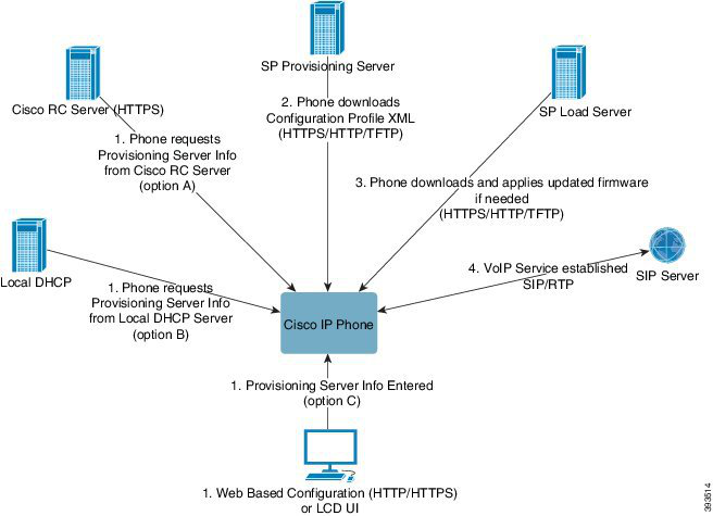
At a high level, the phone provisioning process is:
1.
If the phone is not yet configured, the provisioning server information is applied to the phone via one of
the following options:
a.
Downloaded from the Cisco EDOS RC server via HTTPS.
b.
Queried from the local DHCP server.
c.
Entered via the Cisco phone web based configuration utility.
2.
The phone downloads and applies the configuration XML via HTTPS, HTTP, or TFTP using provisioning
server information.
3.
The phone downloads and applies the updated firmware, if needed, via HTTPS, HTTP, or TFTP.
4.
The VOIP service establishes using the specified configuration and firmware.
In this document, the terms phone and device mean the ATA.
Deployment
These ATAs provide convenient mechanisms for provisioning, based on two deployment models:
• Bulk distribution—The service provider acquires these ATAs in bulk quantity and either preprovisions
them in-house or purchases RC units from Cisco. The devices are then issued to the customers as part
of a VoIP service contract.
• Retail distribution—The customer purchases the ATA from a retail outlet and requests VoIP service
from the service provider. The service provider must then support the secure remote configuration of the
device.
Cisco ATA 191 and ATA 192 Analog Telephone Adapter Provisioning Guide for Multiplatform Firmware
2
Deployment and Provisioning
Deployment
Page 11
Bulk Distribution
In this model, the service provider issues phones to its customers as part of a VoIP service contract. The
devices are either RC units or preprovisioned in-house.
Cisco preprovisions RC units to resynchronize with a Cisco server that downloads the device profile and
firmware updates.
A service provider can preprovision phones with the desired parameters, including the parameters that control
resynchronization, through various methods:
• In-house by using DHCP and TFTP
• Remotely by using TFTP, HTTP, or HTTPS
• A combination of in-house and remote provisioning
Related Topics
Remote Customization (RC) Distribution, on page 40
Retail Distribution
In a retail distribution model, a customer purchases a phone and subscribes to a particular service. The Internet
Telephony Service Provider (ITSP) sets up and maintains a provisioning server, and preprovisions the phone
to resynchronize with the service provider server.
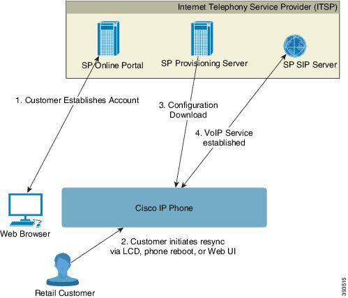
Figure 1: Retail Distribution
The customer signs on to the service and establishes a VoIP account, possibly through an online portal, and
binds the device to the assigned service account. The unprovisioned phone is instructed to resync with a
specific provisioning server through a resync URL command.
Cisco ATA 191 and ATA 192 Analog Telephone Adapter Provisioning Guide for Multiplatform Firmware
3
Deployment and Provisioning
Bulk Distribution
Page 12
In the following example, a device at the DHCP-assigned IP address 192.168.1.102 is instructed to provision
itself to the SuperVoIP service:
http://192.168.1.102/admin/resync?https://prov.supervoip.com/cisco-init/ata.cfg
For both initial and permanent access, the provisioning server relies on the phone client certificate for
authentication. The provisioning server supplies correct configuration parameter values based on the associated
service account.
When the device is powered up or a specified time elapses, the phone resynchronizes and downloads the latest
parameters. These parameters can address goals such as setting up a hunt group, setting speed dial numbers,
and limiting the features that a user can modify.
Related Topics
In-House Device Preprovisioning, on page 41
Resynchronization Process
The firmware for each phone includes an administration web server that accepts new configuration parameter
values. The phone may be instructed to resynchronize configuration after reboot, or at scheduled intervals
with a specified provisioning server through a resync URL command in the device profile.
By default, the web server is enabled. To disable or enable the Web server, use the resync URL command.
If needed, an immediate resynchronization may be requested via a “resync" action URL.
Example
http://192.168.1.102/admin/resync?https://prov.supervoip.com/cisco-init/ata.cfg
In this example, a device at the DHCP-assigned IP address 192.168.1.102 is instructed to provision itself to
the SuperVoIP service at prov.supervoip.com. The Customer ID number for the new account is 1234abcd.
The remote provisioning server associates the phone that is performing the resync request with the account,
based on the URL and Customer ID.
Through this initial resync operation, the phone is configured in a single step. The phone is automatically
directed to resync thereafter to a permanent URL on the server.
For both initial and permanent access, the provisioning server relies on the client certificate for authentication.
The server supplies configuration parameter values based on the associated service account.
Provisioning
A phone can be configured to resynchronize its internal configuration state to match a remote profile periodically
and on power-up. The phone contacts a normal provisioning server (NPS) or an access control server (ACS).
By default, a profile resync is only attempted when the phone is idle. This practice prevents an upgrade that
would trigger a software reboot and interrupt a call. If intermediate upgrades are required to reach a current
upgrade state from an older release, the upgrade logic can automate multistage upgrades.
Cisco ATA 191 and ATA 192 Analog Telephone Adapter Provisioning Guide for Multiplatform Firmware
4
Deployment and Provisioning
Resynchronization Process
Page 13
Normal Provisioning Server
The Normal Provisioning Server (NPS) can be a TFTP, HTTP, or HTTPS server. A remote firmware upgrade
is achieved by using TFTP or HTTP, or HTTPS, because the firmware does not contain sensitive information.
Although HTTPS is recommended, communication with the NPS does not require the use of a secure protocol
because the updated profile can be encrypted by a shared secret key. For more information about utilizing
HTTPS, see Communication Encryption, on page 7. Secure first-time provisioning is provided through a
mechanism that uses SSL functionality. An unprovisioned phone can receive a 256-bit symmetric key encrypted
profile that is targeted for that device.
TR-069
The digital subscriber line (DSL) Forum TR-069, CPE WAN Management Protocol (CWMP), is used for
communications between a customer premise equipment (CPE) device and an autoconfiguration server (ACS).
The TR-069 Agent manages a collection of CPE devices, with the primary capability for auto-configuration
and dynamic service provisioning, software image management, status and performance monitoring, and
diagnostics.
It supports multiple scenarios, including:
• Device administration—Authenticates administrators, authorizes commands, and provides an audit trail
• Remote Access—Works with VPN and other remote network access devices to enforce access policies
• Network admission control—Communicates with posture and audit servers to enforce admission control
policies
The TR-069 Agent CPE devices must be set up and enabled for TR-069. An ACS used to communicate with
the CPE must be TR-069 compliant in order to enable the TR-069 Agent.
Provisioning States
The provisioning process involves these provisioning states.
Description
State
The device returns to a fully unprovisioned state; all configurable parameters regain their default
values.
Manufacturing reset can be performed in these ways:
• Through the IVR sequence ****73738#1#.
• Press the reset button on the ATA.
• Use the web interface to reset the ATA to factory default settings.
On phones that do not support IVR, press the reset button or LCD factory reset entry to reset it to
the default values.
Allowing the end user to perform a manufacturing reset guarantees that the device can always be
returned to an accessible state.
MFG-RESET Manufacturing
Reset
Cisco ATA 191 and ATA 192 Analog Telephone Adapter Provisioning Guide for Multiplatform Firmware
5
Deployment and Provisioning
Normal Provisioning Server
Page 14
Description
State
The Profile_Rule parameter points to a device-specific configuration profile by using a provisioning
server that is specific to the service provider. The methods for initiating resynchronization are:
• Autoconfiguration with a local DHCP server. A TFTP server name or IPv4 address is specified
by DHCP. The TFTP server includes the Profile_Rule parameter in the configuration file.
• Enter a resync URL. The URL starts a web browser and requests a resync to a specific TFTP
server by entering the URL syntax:
http://x.x.x.x/admin/resync?tftp://prvserv/device.cfg, where:
• x.x.x.x is the IP address of the IP Telephony device,
• prvserv is the target TFTP server,
• device.cfg is the name of the configuration file on the server.
• Edit the Profile_Rule parameter by opening the provisioning pane on the web interface and
entering the TFTP URL in the Profile_Rule parameter. For example,
tftp://prserv/spa112.cfg.
• Modify the configuration file Profile_Rule and to contact a specific TFTP server and request
a configuration file identified by the MAC-address. For example, this entry contacts a
provisioning server, requesting a profile unique to the device with a MAC address identified
by the $MA parameter:
Profile_Rule tftp.callme.com/profile/$MA/spa112.cfg;
SP-CUST Service Provider
Customization
An initial, device-unique CFG file is targeted to a IP Telephony device by compiling the CFG file
with the SPC --target option. This provides an encryption that does not require the exchange of
keys.
The initial, device-unique CFG file reconfigures the device profile to enable stronger encryption
by programming a 256-bit encryption key and pointing to a randomly generated TFTP directory.
For example, the CFG file might contain:
Profile_Rule [--key $A] tftp.callme.com/profile/$B/spa112.cfg;
GPP_A 8e4ca259…; # 256 bit key
GPP_B Gp3sqLn…; # random CFG file path directory
SEC-PRV-1 Secure
Provisioning—Initial
Configuration
Profile resync operations subsequent to the initial SECPRV-1 provisioning retrieve the 256-bit
encrypted CFG files that maintain the IP Telephony device in a state synchronized to the provisioning
server.
The profile parameters are reconfigured and maintained through this strongly encrypted profile.
The encryption key and random directory location in the SEC-PRV-2 configuration can be changed
periodically for extra security.
SEC-PRV-2 Secure
Provisioning—Full
Configuration
Configuration Access Control
The phone firmware provides mechanisms for restricting end-user access to some parameters. The firmware
provides specific privileges for sign-in to an Admin account or a User account. Each can be independently
password protected.
Cisco ATA 191 and ATA 192 Analog Telephone Adapter Provisioning Guide for Multiplatform Firmware
6
Deployment and Provisioning
Configuration Access Control
Page 15
• Admin account–Allows the service provider full access to all administration web server parameters.
• User account–Allows the user to configure a subset of the administration web server parameters.
The service provider can restrict the user account in the provisioning profile in the following ways:
• Indicate which configuration parameters are available to the user account when creating the configuration.
• Disable user access to the administration web server.
• Restrict the Internet domains accessed by the device for resync, upgrades, or SIP registration for Line 1.
Related Topics
Element Tag Properties, on page 14
Access Control, on page 16
Communication Encryption
The configuration parameters that are communicated to the device can contain authorization codes or other
information that protect the system from unauthorized access. It is in the service provider’s interest to prevent
unauthorized customer activity. It is in the customer’s interest to prevent the unauthorized use of the account.
The service provider can encrypt the configuration profile communication between the provisioning server
and the device, in addition to restricting access to the administration web server.
Additional Information
Related Documentation
Use the following sections to obtain related information.
Cisco ATA 190 Series Documentation
Refer to publications that are specific to your language and call control system. Navigate from the following
documentation URL:
https://www.cisco.com/c/en/us/products/unified-communications/ata-190-series-analog-telephone-adapters/
index.html
Cisco ATA 190 Series Firmware Support Policy
For information on the support policy for ATAs, see http://www.cisco.com/c/en/us/support/docs/
collaboration-endpoints/unified-ip-phone-7900-series/116684-technote-ipphone-00.html.
Phone Behavior During Times of Network Congestion
Anything that degrades network performance can affect phone audio and, in some cases, can cause a call to
drop. Sources of network degradation can include, but are not limited to, the following activities:
• Administrative tasks, such as an internal port scan or security scan.
Cisco ATA 191 and ATA 192 Analog Telephone Adapter Provisioning Guide for Multiplatform Firmware
7
Deployment and Provisioning
Communication Encryption
Page 16
• Attacks that occur on your network, such as a Denial of Service attack.
Communications, Services, and Additional Information
• To receive timely, relevant information from Cisco, sign up at Cisco Profile Manager.
• To get the business results you’re looking for with the technologies that matter, visit Cisco Services.
• To submit a service request, visit Cisco Support.
• To discover and browse secure, validated enterprise-class apps, products, solutions and services, visit
Cisco DevNet.
• To obtain general networking, training, and certification titles, visit Cisco Press.
• To find warranty information for a specific product or product family, access Cisco Warranty Finder.
Cisco ATA 191 and ATA 192 Analog Telephone Adapter Provisioning Guide for Multiplatform Firmware
8
Deployment and Provisioning
Communications, Services, and Additional Information
Page 17
C H A P T E R 2
New and Changed Information
• New and Changed for Firmware Release 11.3(1), on page 9
• New and Changed for Firmware Release 11.2(5), on page 10
• New and Changed for Firmware Release 11.2(4), on page 10
• New and Changed for Firmware Release 11.2(3), on page 10
• New and Changed for Firmware Release 11.2(2), on page 11
• New and Changed for Firmware Release 11.2(1), on page 11
New and Changed for Firmware Release 11.3(1)
New and Changed
Revision
Voice Parameters, on page 75
XML Open Format Sample, on page 171
Updated the topics to add the following parameters:
• MediaSec_Request
• MediaSec_Over_TLS_Only
• MIC_Cert_Refresh_Enable
• MIC_Cert_Refresh_Rule
• Survivability_Test_Mode
• Survivability_Proxy
• Survivability_Proxy_Fallback_Intvl
• TLS_Min_Version
Cisco ATA 191 and ATA 192 Analog Telephone Adapter Provisioning Guide for Multiplatform Firmware
9

Page 18
New and Changed for Firmware Release 11.2(5)
New and Changed
Revision
Voice Parameters, on page 75
XML Open Format Sample, on page 171
Updated the topics to add the following parameters:
• FIPS_Mode
• Auth_Support_RFC8760
• TLS_Min_Version
• Encryption_Method
• Reversed_Auth_Realm
New and Changed for Firmware Release 11.2(4)
New and Changed
Revision
Voice Parameters, on page 75
Updated the default value of the parameters
<FAX_Enable_T38_1> and <FAX_Enable_T38_2>
Voice Parameters, on page 75
Updated the description of the parameters
<NAT_Keep_Alive_Msg_1> and
<NAT_Keep_Alive_Msg_2>
XML Open Format Sample, on page 171
Updated the values of <NAT_Keep_Alive_Msg_1>
and <NAT_Keep_Alive_Msg_2>
XML Open Format Sample, on page 171
Web_Management, on page 160
Updated the parameters in <Web_Management>
Voice Parameters, on page 75
Updated the description of the parameters
<Proxy_Fallback_Intvl_1> and
<Proxy_Fallback_Intvl_2>
Redundant Provisioning Servers, on page 47
Updated the topic to mention the maximum number
of A records for SRV record
New and Changed for Firmware Release 11.2(3)
New and Changed
Revision
HTTP_Proxy Parameters, on page 152
Added the topic for the HTTP Proxy Support feature
XML Open Format Sample, on page 171
Updated the topic for the HTTP Proxy Support feature
Cisco ATA 191 and ATA 192 Analog Telephone Adapter Provisioning Guide for Multiplatform Firmware
10
New and Changed Information
New and Changed for Firmware Release 11.2(5)
Page 19
New and Changed
Revision
Remote Customization (RC) Distribution, on page 40
Updated the topic for the Out of Box Provisioning
Enhancement feature
Voice Parameters, on page 75
Updated the topic to add the value range of the
parameters Call_Back_Delay, VMWI_Refresh_Intvl,
DTMF_Playback_Length, and DTMF_Playback_Level
New and Changed for Firmware Release 11.2(2)
New and Changed
Revision
Voice Parameters, on page 75
Updated the description of the parameters
SIP_Transport_1 and SIP_Transport_2
Voice Parameters, on page 75
Updated the topic to add the new parameters
Secure_Call_Option_1 and Secure_Call_Option_2
XML Open Format Sample, on page 171
Updated the topic to add the new parameters
Secure_Call_Option_1 and Secure_Call_Option_2
New and Changed for Firmware Release 11.2(1)
New and Changed
Revision
Log_Configuration Parameters, on page 165
Updated the topic to show all the log modules
XML Open Format Sample, on page 171
Updated the topic to add the new log module options
Voice Parameters, on page 75
Updated the topic to add new parameters
XML Open Format Sample, on page 171
Updated the sample to add new parameters
Cisco ATA 191 and ATA 192 Analog Telephone Adapter Provisioning Guide for Multiplatform Firmware
11
New and Changed Information
New and Changed for Firmware Release 11.2(2)
Page 20
Cisco ATA 191 and ATA 192 Analog Telephone Adapter Provisioning Guide for Multiplatform Firmware
12
New and Changed Information
New and Changed for Firmware Release 11.2(1)
Page 21
C H A P T E R 3
Provisioning Formats
• Configuration Profiles , on page 13
• Configuration Profile Formats, on page 13
• Open Profile (XML) Compression and Encryption, on page 17
• Application of a Profile to the Phone, on page 22
• Provisioning Parameter Types, on page 23
• Data Types, on page 30
• Profile Updates and Firmware Upgrades, on page 33
• Access the Phone Web Interface, on page 36
Configuration Profiles
The phone accepts configuration in an XML format.
For detailed information about your phone, refer to the administration guide for your particular device. Each
guide describes the parameters that can be configured through the administration web server.
Configuration Profile Formats
The configuration profile defines the parameter values for the phone.
The configuration profile XML format uses standard XML authoring tools to compile the parameters and
values.
Only the UTF-8 charset is supported. If you modify the profile in an editor, do not change the encoding format;
otherwise, the phone cannot recognize the file.
Note
Each phone has a different feature set and therefore, a different set of parameters.
XML Format (XML) Profile
The open format profile is a text file with XML-like syntax in a hierarchy of elements, with element attributes
and values. This format lets you use standard tools to create the configuration file. A configuration file in this
Cisco ATA 191 and ATA 192 Analog Telephone Adapter Provisioning Guide for Multiplatform Firmware
13


Page 22
format can be sent from the provisioning server to the phone during a resync operation. The file can be sent
without compilation as a binary object.
The phone can accept configuration formats that standard tools generate. This feature eases the development
of back-end provisioning server software that generates configuration profiles from existing databases.
To protect confidential information in the configuration profile, the provisioning server delivers this type of
file to the phone over a channel secured by TLS. Optionally, the file can be compressed by using the gzip
deflate algorithm (RFC1951).
The file can be encrypted with 256-bit AES symmetric key encryption.
Example: Open Profile Format
<flat-profile>
<Resync_On_Reset> Yes </Resync_On_Reset>
<Resync_Periodic> 7200 </Resync_Periodic>
<Profile_Rule> tftp://prov.telco.com:6900/cisco/config/CP_xxxx_MPP.cfg</Profile_Rule>
</flat-profile>
The <flat-profile> element tag encloses all parameter elements that the phone recognizes.
Configuration File Components
A configuration file can include these components:
• Element tags
• Attributes
• Parameters
• Formatting features
• XML comments
Element Tag Properties
• The XML provisioning format and the Web UI allow the configuration of the same settings. The XML
tag name and the field names in the Web UI are similar but vary due to XML element name restrictions.
For example, underscores (_) instead of " ".
• The phone recognizes elements with proper parameter names that are encapsulated in the special
<flat-profile> element.
• Element names are enclosed in angle brackets.
• Most element names are similar to the field names in the administration web pages for the device, with
the following modifications:
• Element names may not include spaces or special characters. To derive the element name from the
administration web field name, substitute an underscore for every space or the special characters [,
], (, ), or /.
Example: The <Resync_On_Reset> element represents the Resync On Reset field.
Cisco ATA 191 and ATA 192 Analog Telephone Adapter Provisioning Guide for Multiplatform Firmware
14
Provisioning Formats
Configuration File Components
Page 23
• Each element name must be unique. In the administration web pages, the same fields can appear on
multiple web pages, such as the Line, User, and Extension pages. Append [n] to the element name
to indicate the number that is shown in the page tab.
Example: The <Dial_Plan_1_> element represents the Dial Plan for Line 1.
• Each opening element tag must have a matching closing element tag. For example:
<flat-profile>
<Resync_On_Reset> Yes
</Resync_On_Reset>
<Resync_Periodic> 7200
</Resync_Periodic>
<Profile_Rule>tftp://prov.telco.com: 6900/cisco/config/CP_xxxx_MPP.cfg
</Profile_Rule>
</flat-profile>
• Element tags are case-sensitive.
• Empty element tags are allowed and will be interpreted as configuring the value to be empty. Enter the
opening element tag without a corresponding element tag, and insert a space and a forward slash before
the closing angle bracket (>). In this example, Profile Rule B is empty:
<Profile_Rule_B />
• An empty element tag can be used to prevent the overwriting of any user-supplied values during a resync
operation. In the following example, the user speed dial settings are unchanged:
<flat-profile>
<Speed_Dial_2_Name ua="rw"/>
<Speed_Dial_2_Number ua="rw"/>
<Speed_Dial_3_Name ua="rw"/>
<Speed_Dial_3_Number ua="rw"/>
<Speed_Dial_4_Name ua="rw"/>
<Speed_Dial_4_Number ua="rw"/>
<Speed_Dial_5_Name ua="rw"/>
<Speed_Dial_5_Number ua="rw"/>
<Speed_Dial_6_Name ua="rw"/>
<Speed_Dial_6_Number ua="rw"/>
<Speed_Dial_7_Name ua="rw"/>
<Speed_Dial_7_Number ua="rw"/>
<Speed_Dial_8_Name ua="rw"/>
<Speed_Dial_8_Number ua="rw"/>
<Speed_Dial_9_Name ua="rw"/>
<Speed_Dial_9_Number ua="rw"/>
</flat-profile>
• Use an empty value to set the corresponding parameter to an empty string. Enter an opening and closing
element without any value between them. In the following example, the GPP_A parameter is set to an
empty string.
<flat-profile>
<GPP_A>
</GPP_A>
</flat-profile>
• Unrecognized element names are ignored.
Cisco ATA 191 and ATA 192 Analog Telephone Adapter Provisioning Guide for Multiplatform Firmware
15
Provisioning Formats
Element Tag Properties
Page 24
Access Control
If the <Phone-UI-User-Mode> parameter is enabled, the phone GUI honors the user access attribute of the
relevant parameters when the GUI presents a menu item.
For menu entries that are associated with a single configuration parameter:
• Provisioning the parameter with “ua=na” (“ua” stands for “user access”) attribute makes the entry
disappear.
• Provisioning the parameter with “ua=ro” attribute makes the entry read-only and non-editable.
For menu entries that are associated with multiple configuration parameters:
• Provisioning all concerned parameters with “ua=na” attribute makes the entries disappear.
Related Topics
Configuration Access Control, on page 6
Parameter Properties
These properties apply to the parameters:
• Any parameters that are not specified by a profile are left unchanged in the phone.
• Unrecognized parameters are ignored.
• If the Open format profile contains multiple occurrences of the same parameter tag, the last such occurrence
overrides any earlier ones. To avoid inadvertent override of configuration values for a parameter, we
recommend that each profile specify at most one instance of a parameter.
• The last profile processed takes precedence. If multiple profiles specify the same configuration parameter,
the value of the latter profile takes precedence.
String Formats
These properties apply to the formatting of the strings:
• Comments are allowed through standard XML syntax.
<!-- My comment is typed here -->
• Leading and trailing white space is allowed for readability but is removed from the parameter value.
• New lines within a value are converted to spaces.
• An XML header of the form <? ?> is allowed, but the phone ignores it.
• To enter special characters, use basic XML character escapes, as shown in the following table.
XML Escape Sequence
Special Character
&
& (ampersand)
<
< (less than)
>
(greater than)
Cisco ATA 191 and ATA 192 Analog Telephone Adapter Provisioning Guide for Multiplatform Firmware
16
Provisioning Formats
Access Control
Page 25
XML Escape Sequence
Special Character
'
’ (apostrophe)
"
” (double quote)
In the following example, character escapes are entered to represent the greater than and less than symbols
that are required in a dial plan rule. This example defines an information hotline dial plan that sets the
<Dial_Plan_1_> parameter (Admin Login > advanced > Voice > Ext (n)) equal to (S0 <:18005551212>).
<flat-profile>
<Dial_Plan_1_>
(S0 <:18005551212>)
</Dial_Plan_1_>
</flat-profile>
• Numeric character escapes, using decimal and hexadecimal values (s.a. ( and .), are translated.
• The phone firmware only supports ASCII characters.
Open Profile (XML) Compression and Encryption
The Open configuration profile can be compressed to reduce the network load on the provisioning server.
The profile can also be encrypted to protect confidential information. Compression is not required, but it must
precede encryption.
Related Topics
Configuration Profile Formats, on page 13
Open Profile Compression
The supported compression method is the gzip deflate algorithm (RFC1951). The gzip utility and the
compression library that implements the same algorithm (zlib) are available from Internet sites.
To identify compression, the phone expects the compressed file to contain a gzip compatible header. Invocation
of the gzip utility on the original Open profile generates the header. The phone inspects the downloaded file
header to determine the file format.
For example, if profile.xml is a valid profile, the file profile.xml.gz is also accepted. Either of the following
commands can generate this profile type:
• >gzip profile.xml
Replaces original file with compressed file.
• >cat profile.xml | gzip > profile.xml.gz
Leaves original file in place, produces new compressed file.
A tutorial on compression is provided in the Compress an Open Profile with Gzip, on page 62 section.
Cisco ATA 191 and ATA 192 Analog Telephone Adapter Provisioning Guide for Multiplatform Firmware
17
Provisioning Formats
Open Profile (XML) Compression and Encryption
Page 26
AES-256-CBC Encryption
Symmetric key encryption can be used to encrypt an Open configuration profile, whether the file is compressed
or not. The supported encryption algorithm is the American Encryption Standard (AES), using 256-bit keys,
applied in cipher block chaining mode.
Compression must precede encryption for the phone to recognize a compressed and encrypted Open format
profile. Encrypt a Profile with OpenSSL, on page 63 provides a tutorial on encryption.
Note
The OpenSSL encryption tool, available for download from various Internet sites, can perform the encryption.
Support for 256-bit AES encryption may require recompilation of the tool to enable the AES code. The
firmware has been tested against version openssl-1.1.1d.
For an encrypted file, the profile expects the file to have the same format as generated by the following
command:
example encryption key = SecretPhrase1234
openssl enc -aes-256-cbc -md md5 -k SecretPhrase1234 -in profile.xml -out profile.cfg
analogous invocation for a compressed xml file
openssl enc –e –aes-256-cbc –k SecretPhrase1234 –in profile.xml.gz –out profile.cfg
A lowercase -k precedes the secret key, which can be any plain text phrase, and which is used to generate a
random 64-bit salt. With the secret specified by the -k argument, the encryption tool derives a random 128-bit
initial vector and the actual 256-bit encryption key.
When this form of encryption is used on a configuration profile, the phone must be informed of the secret key
value to decrypt the file. This value is specified as a qualifier in the profile URL. The syntax is as follows,
using an explicit URL:
[--key “SecretPhrase1234”] http://prov.telco.com/path/profile.cfg
This value is programmed by using one of the Profile_Rule parameters.
The key must be preprovisioned into the unit at an earlier time. Bootstrap of the secret key can be accomplished
securely by using HTTPS.
Pre-encrypting configuration profiles offline, with symmetric key encryption, allows the use of HTTP for
resyncing profiles. The provisioning server uses HTTPS to handle initial provisioning of the phone after
deployment. This feature reduces the load on the HTTPS server in large-scale deployments.
The final filename does not require a specific format, but a filename that ends with the .cfg extension
normally indicates a configuration profile.
Related Topics
Encrypt a Profile with OpenSSL, on page 63
Macro Expansion
Several provisioning parameters undergo macro expansion internally prior to being evaluated. This preevaluation
step provides greater flexibility in controlling the phone resync and upgrade activities.
Cisco ATA 191 and ATA 192 Analog Telephone Adapter Provisioning Guide for Multiplatform Firmware
18
Provisioning Formats
AES-256-CBC Encryption

Page 27
These parameter groups undergo macro expansion before evaluation:
• Resync_Trigger_*
• Profile_Rule*
• Log_xxx_Msg
• Upgrade_Rule
Under certain conditions, some general-purpose parameters (GPP_*) also undergo macro expansion, as
explicitly indicated in Optional Resync Arguments, on page 21.
During macro expansion, the contents of the named variables replace expressions of the form $NAME and
$(NAME). These variables include general-purpose parameters, several product identifiers, certain event
timers, and provisioning state values. For a complete list, see Macro Expansion Variables, on page 72.
In the following example, the expression $(MAU) is used to insert the MAC address 000E08012345.
The administrator enters: $(MAU)config.cfg
The resulting macro expansion for a device with MAC address 000E08012345 is:
000E08012345config.cfg
If a macro name is not recognized, it remains unexpanded. For example, the name STRANGE is not recognized
as a valid macro name, while MAU is recognized as a valid macro name.
The administrator enters: $STRANGE$MAU.cfg
The resulting macro expansion for a device with MAC address 000E08012345 is:
$STRANGE000E08012345.cfg
Macro expansion is not applied recursively. For example, $$MAU” expands into $MAU” (the $$ is expanded),
and does not result in the MAC address.
The contents of the special purpose parameters, GPP_SA through GPP_SD, are mapped to the macro
expressions $SA through $SD. These parameters are only macro expanded as the argument of the --key ,
--uid, and --pwd options in a resync URL.
Conditional Expressions
Conditional expressions can trigger resync events and select from alternate URLs for resync and upgrade
operations.
Conditional expressions consist of a list of comparisons, separated by the and operator. All comparisons must
be satisfied for the condition to be true.
Each comparison can relate to one of the following three types of literals:
• Integer values
• Software or hardware version numbers
• Doubled-quoted strings
Version Numbers
Cisco ATA 191 and 192—ATA19x.v1-v2-v3MPP-BN (where BN is the Build Number)
The comparing string must use the same format. Otherwise, a format parsing error results.
Cisco ATA 191 and ATA 192 Analog Telephone Adapter Provisioning Guide for Multiplatform Firmware
19
Provisioning Formats
Conditional Expressions
Page 28
In the software version, v1-v2-v3-v4 can specify different digits (0-99). When comparing the software version,
v1-v2-v3-v4 is compared in sequence, and the leftmost digits take precedence over the latter ones.
If v[x] includes only numeric digits, the digits are compared; if v[x] includes numeric digits and alpha characters,
the digits are compared first, then the characters are compared in alphabetical order.
Example of Valid Version Number
ATA19x.11-1-0MPP-BN
By contrast: 11.1.0 is an invalid format.
Comparison
ATA19x.11-1-0MPP-BN < ATA19x.11-1-1MPP-BN
Quoted strings can be compared for equality or inequality. Integers and version numbers can also be
compared arithmetically. The comparison operators can be expressed as symbols or as acronyms.
Acronyms are convenient for expressing the condition in an Open format profile.
Applicable to Q
Operands
Applicable to Integer and
Version Operands
Description
Alternate Syntax
Operator
Yes
Yes
equal to
eq
Yes
Yes
not equal to
ne
!=
No
Yes
less than
lt
<
No
Yes
less than or equal to
le
<=
No
Yes
greater than
gt
No
Yes
greater than or equal to
ge
=
Yes
Yes
and
AND
It is important to enclose macro variables in double quotes where a string literal is expected. Don't
do so where a number or version number is expected.
When used in the context of the Profile_Rule* and Upgrade_Rule parameters, conditional expressions
must be enclosed within the syntax “(expr)?” as in this upgrade rule example. Remember to replace
BN with the build number of your firmware load to upgrade to.
• For Firmware Release 11.1(0)SR3 and previous
Since the version comparison rule changes in the 11.1(0)SR4 release, use the following
conditional expression to upgrade the current firmware to Firmware Release 11.1(0)SR4 or
later:
("$SWVER" ne "11-1-0MPP")? http://ps.tell.com/sw/ATA19x.11-1-0MPP-BN.loads
• For Firmware Release 11.1(0)SR4 and later
($SWVER ne 11-1-0MPP)? http://ps.tell.com/sw/ATA19x.11-1-0MPP-BN.loads
Do not use the preceding syntax with parentheses to configure the Resync_Trigger_* parameters.
Cisco ATA 191 and ATA 192 Analog Telephone Adapter Provisioning Guide for Multiplatform Firmware
20
Provisioning Formats
Conditional Expressions
Page 29
URL Syntax
Use the Standard URL syntax to specify how to retrieve configuration files and firmware loads in Profile_Rule*
and Upgrade_Rule parameters, respectively. The syntax is as follows:
[ scheme:// ] [ server [:port]] filepath
Where scheme is one of these values:
• tftp
• http
• https
If scheme is omitted, tftp is assumed. The server can be a DNS-recognized hostname or a numeric IP address.
The port is the destination UDP or TCP port number. The filepath must begin with the root directory (/); it
must be an absolute path.
If server is missing, the tftp server specified through DHCP (option 66) is used.
For upgrade rules, the server must be specified.
Note
If port is missing, the standard port for the specified scheme is used. Tftp uses UDP port 69, http uses TCP
port 80, https uses TCP port 443.
A filepath must be present. It need not necessarily refer to a static file, but can indicate dynamic content
obtained through CGI.
Macro expansion applies within URLs. The following are examples of valid URLs:
/$MA.cfg
/cisco/cfg.xml
192.168.1.130/profiles/init.cfg
tftp://prov.call.com/cpe/cisco$MA.cfg
http://neptune.speak.net:8080/prov/$D/$E.cfg
https://secure.me.com/profile?Linksys
When using DHCP option 66, the empty syntax is not supported by upgrade rules. It is only applicable for
Profile Rule*.
Optional Resync Arguments
Optional arguments, key, uid, and pwd, can precede the URLs entered in Profile_Rule* parameters,
collectively enclosed by square brackets.
key
The key option is used to specify an encryption key. Decryption of profiles that have been encrypted with an
explicit key is required. The key itself is specified as a (possibly quoted) string following the term --key.
Cisco ATA 191 and ATA 192 Analog Telephone Adapter Provisioning Guide for Multiplatform Firmware
21
Provisioning Formats
URL Syntax

Page 30
Usage Examples
[--key VerySecretValue]
[--key “my secret phrase”]
[--key a37d2fb9055c1d04883a0745eb0917a4]
The bracketed optional arguments are macro expanded. Special purpose parameters, GPP_SA through
GPP_SD, are macro expanded into macro variables, $SA through $SD, only when they are used as
key option arguments. See these examples:
[--key $SC]
[--key “$SD”]
In Open format profiles, the argument to --key must be the same as the argument to the -k option
that is given to openssl.
uid and pwd
The uid and pwd options can be used to specify the userID and password that will be sent in response to
HTTP Basic and Digest authentication challenges when the specified URL is requested. The bracketed optional
arguments are macro expanded. Special purpose parameters, GPP_SA through GPP_SD, are macro expanded
into macro variables, $SA through $SD, only when they are used as key option arguments. See these examples:
GPP_SA = MyUserID
GPP_SB = MySecretPassword
[--uid $SA --pwd $SB] https://provisioning_server_url/path_to_your_config/your_config.xml
would then expand to:
[--uid MyUserID --pwdMySecretPassword]
https://provisioning_server_url/path_to_your_config/your_config.xml
Application of a Profile to the Phone
After you create an XML configuration script, it must be passed to the phone for application. To apply the
configuration, you can either download the configuration file to the phone from a TFTP, HTTP, or HTTPS
server using a web browser or by using cURL command line utility.
Download the Configuration File to the Phone from a TFTP Server
Complete these steps to download the configuration file to a TFTP server application on your PC.
Procedure
Step 1
Connect your PC to the phone LAN.
Step 2
Run a TFTP server application on the PC and ensure that the configuration file is available in the TFTP root
directory.
Cisco ATA 191 and ATA 192 Analog Telephone Adapter Provisioning Guide for Multiplatform Firmware
22
Provisioning Formats
uid and pwd
Page 31
Step 3
In a web browser, enter the phone LAN IP address, the IP address of the computer, the filename, and the login
credentials. Use this format:
http://<WAN_IP_Address>/admin/resync?tftp://<PC_IP_Address>/<file_name>&xuser=admin&xpassword=<password>
Example:
http://192.168.15.1/admin/resync?tftp://192.168.15.100/my_config.xml&xuser=admin&xpassword=admin
Download the Configuration File to the Phone with cURL
Complete these steps to download the configuration to the phone by using cURL. This command-line tool is
used to transfer data with a URL syntax. To download cURL, visit:
https://curl.haxx.se/download.html
We recommend that you do not use cURL to post the configuration to the phone because the username and
password might get captured while using cURL.
Note
Procedure
Step 1
Connect your PC to the LAN port of the phone.
Step 2
Download the configuration file to the phone by entering the following cURL command:
curl –d @my_config.xml
“http://192.168.15.1/admin/config.xml&xuser=admin&xpassword=admin”
Provisioning Parameter Types
This section describes the provisioning parameters broadly organized according to function:
These provisioning parameter types exist:
• General Purpose
• Enables
• Triggers
• Configurable Schedules
• Profile Rules
• Upgrade Rule
Related Topics
Voice Parameters, on page 75
Cisco ATA 191 and ATA 192 Analog Telephone Adapter Provisioning Guide for Multiplatform Firmware
23
Provisioning Formats
Download the Configuration File to the Phone with cURL

Page 32
Router Configuration Parameters, on page 123
General Purpose Parameters
The general-purpose parameters GPP_* (Admin Login > advanced > Voice > Provisioning) are used as
free string registers when configuring the phone to interact with a particular provisioning server solution. The
GPP_* parameters are empty by default. They can be configured to contain diverse values, including the
following:
• Encryption keys
• URLs
• Multistage provisioning status information.
• Post request templates
• Parameter name alias maps
• Partial string values, eventually combined into complete parameter values.
The GPP_* parameters are available for macro expansion within other provisioning parameters. For this
purpose, single-letter uppercase macro names (A through P) suffice to identify the contents of GPP_A through
GPP_P. Also, the two-letter uppercase macro names SA through SD identify GPP_SA through GPP_SD as
a special case when used as arguments of the following URL options:
key, uid, and pwd
These parameters can be used as variables in provisioning and upgrade rules. They are referenced by prefixing
the variable name with a ‘$’ character, such as $GPP_A.
Use General Purpose Parameters
For example, if GPP_A contains the string ABC, and GPP_B contains 123, the expression $A$B macro
expands into ABC123.
Before you begin
Access the phone administration web page. See Access the Phone Web Interface, on page 36.
Procedure
Step 1
Select Voice > Provisioning.
Step 2
Scroll to the General Purpose Parameters section.
Step 3
Enter valid values in the fields, GPP A through GPP P.
Step 4
Click Submit All Changes.
Cisco ATA 191 and ATA 192 Analog Telephone Adapter Provisioning Guide for Multiplatform Firmware
24
Provisioning Formats
General Purpose Parameters
Page 33
Enable Parameters
The Provision_Enable and Upgrade_Enable parameters control all profile resync and firmware upgrade
operations. These parameters control resyncs and upgrades independently of each other. These parameters
also control resync and upgrade URL commands that are issued through the administration web server. Both
of these parameters are set to Yes by default.
The Resync_From_SIP parameter controls requests for resync operations. A SIP NOTIFY event is sent from
the service provider proxy server to the phone. If enabled, the proxy can request a resync. To do so, the proxy
sends a SIP NOTIFY message that contains the Event: resync header to the device.
The device challenges the request with a 401 response (authorization refused for used credentials). The device
expects an authenticated subsequent request before it honors the resync request from the proxy. The Event:
reboot_now and Event: restart_now headers perform cold and warm restarts, respectively, which are also
challenged.
The two remaining enables are Resync_On_Reset and Resync_After_Upgrade_Attempt. These parameters
determine whether the device performs a resync operation after power-up software reboots and after each
upgrade attempt.
When Resync_On_Reset is enabled, the device introduces a random delay that follows the boot-up sequence
before the reset is performed. The delay is a random time up to the value that the Resync_Random_Delay (in
seconds) specifies. In a pool of phones that power up simultaneously, this delay spreads out the start times of
the resync requests from each unit. This feature can be useful in a large residential deployment, in the case
of a regional power failure.
Triggers
The phone allows you to resync at specific intervals or at a specific time.
Resync at Specific Intervals
The phone is designed to resync with the provisioning server periodically. The resync interval is configured
in Resync_Periodic (seconds). If this value is left empty, the device does not resync periodically.
The resync typically takes place when the voice lines are idle. If a voice line is active when a resync is due,
the phone delays the resync procedure until the line becomes idle again. A resync can cause configuration
parameter values to change.
A resync operation can fail because the phone is unable to retrieve a profile from the server, the downloaded
file is corrupt, or an internal error occurred. The device tries to resync again after a time that is specified in
Resync_Error_Retry_Delay (seconds). If Resync_Error_Retry_Delay is set to 0, the device does not try to
resync again after a failed resync attempt.
If an upgrade fails, a retry is performed after Upgrade_Error_Retry_Delay seconds.
Two configurable parameters are available to conditionally trigger a resync: Resync_Trigger_1 and
Resync_Trigger_2. Each parameter can be programmed with a conditional expression that undergoes macro
expansion. When the resync interval expires (time for the next resync) the triggers, if set, will prevent resync
unless one or more triggers evaluates to true.
The following example condition triggers a resync. In the example, the last phone upgrade attempt has elapsed
more than 5 minutes (300 seconds), and at least 10 minutes (600 seconds) have elapsed since the last resync
attempt.
Cisco ATA 191 and ATA 192 Analog Telephone Adapter Provisioning Guide for Multiplatform Firmware
25
Provisioning Formats
Enable Parameters
Page 34
$UPGTMR gt 300 and $PRVTMR ge 600
Resync at a Specific Time
The Resync_At parameter allows the phone to resync at a specific time. This parameter uses the 24-hour
format (hhmm) to specify the time.
The Resync_At_Random_Delay parameter allows the phone to resync at an unspecified delay in time. This
parameter uses a positive integer format to specify the time.
Flooding the server with resync requests from multiple phones that are set to resync at the same time should
be avoided. To do so, the phone triggers the resync up to 10 minutes after the specified time.
For example, if you set the resync time to 1000 (10 a.m.), the phone triggers the resync anytime between
10:00 a.m. and 10:10 a.m.
By default, this feature is disabled. If the Resync_At parameter is provisioned, the Resync_Periodic parameter
is ignored.
Configurable Schedules
You can configure schedules for periodic resyncs, and you can specify the retry intervals for resync and
upgrade failures by using these provisioning parameters:
• Resync_Periodic
• Resync_Error_Retry_Delay
• Upgrade_Error_Retry_Delay
Each parameter accepts a single delay value (seconds). The new extended syntax allows for a comma-separated
list of consecutive delay elements. The last element in the sequence is implicitly repeated forever.
Optionally, you can use a plus sign to specify another numeric value that appends a random extra delay.
Example 1
In this example, the phone periodically resyncs every 2 hours. If a resync failure occurs, the device retries at
these intervals: 30 minutes, 1 hour, 2 hours, 4 hours. The device continues to try at 4-hour intervals until it
resyncs successfully.
Resync_Periodic=7200
Resync_Error_Retry_Delay=1800,3600,7200,14400
Example 2
In this example, the device periodically resyncs every hour (plus an extra random delay of up to 10 minutes).
In the case of a resync failure, the device retries at these intervals: 30 minutes (plus up to 5 minutes). 1 hour
(plus up to 10 minutes), 2 hours (plus up to 15 minutes). The device continues to try at 2-hour intervals (plus
up to 15 minutes) until it successfully resyncs.
Resync_Periodic=3600+600
Resync_Error_Retry_Delay=1800+300,3600+600,7200+900
Cisco ATA 191 and ATA 192 Analog Telephone Adapter Provisioning Guide for Multiplatform Firmware
26
Provisioning Formats
Resync at a Specific Time
Page 35
Example 3
In this example, if a remote upgrade attempt fails, the device retries the upgrade in 30 minutes, then again
after one more hour, then in two hours. If the upgrade still fails, the device retries every four to five hours
until the upgrade succeeds.
Upgrade_Error_Retry_Delay
1800,3600,7200,14400+3600
Profile Rules
The phone provides multiple remote configuration profile parameters (Profile_Rule*). Thus, each resync
operation can retrieve multiple files that different servers manage.
In the simplest scenario, the device resyncs periodically to a single profile on a central server, which updates
all pertinent internal parameters. Alternatively, the profile can be split between different files. One file is
common for all the phones in a deployment. A separate, unique file is provided for each account. Encryption
keys and certificate information can be supplied by still another profile, stored on a separate server.
Whenever a resync operation is due, the phone evaluates the four Profile_Rule* parameters in sequence:
1.
Profile_Rule
2.
Profile_Rule_B
3.
Profile_Rule_C
4.
Profile_Rule_D
Each evaluation can result in a profile retrieval from a remote provisioning server, with a possible update of
some number of internal parameters. If an evaluation fails, the resync sequence is interrupted, and is retried
again from the beginning specified by the Resync_Error_Retry_Delay parameter (seconds). If all evaluations
succeed, the device waits for the second specified by the Resync_Periodic parameter and then performs another
resync.
The contents of each Profile_Rule* parameter consist of a set of alternatives. The alternatives are separated
by the | (pipe) character. Each alternative consists of a conditional expression, an assignment expression, a
profile URL, and any associated URL options. All these components are optional within each alternative. The
following are the valid combinations, and the order in which they must appear, if present:
[ conditional-expr ] [ assignment-expr ] [[ options ] URL ]
Within each Profile_Rule* parameter, all alternatives except the last one must provide a conditional expression.
This expression is evaluated and is processed as follows:
1.
Conditions are evaluated from left to right, until one is found that evaluates as true (or until one alternative
is found with no conditional expression).
2.
Any accompanying assignment expression is evaluated, if present.
3.
If a URL is specified as part of that alternative, an attempt is made to download the profile that is located
at the specified URL. The system attempts to update the internal parameters accordingly.
If all alternatives have conditional expressions and none evaluates to true (or if the whole profile rule is empty),
the entire Profile_Rule* parameter is skipped. The next profile rule parameter in the sequence is evaluated.
Cisco ATA 191 and ATA 192 Analog Telephone Adapter Provisioning Guide for Multiplatform Firmware
27
Provisioning Formats
Profile Rules
Page 36
Example 1
This example resyncs unconditionally to the profile at the specified URL, and performs an HTTP GET request
to the remote provisioning server:
http://remote.server.com/cisco/$MA.cfg
Example 2
In this example, the device resyncs to two different URLs, depending on the registration state of Line 1. In
case of lost registration, the device performs an HTTP POST to a CGI script. The device sends the contents
of the macro expanded GPP_A, which may provide additional information on the device state:
($PRVTMR ge 600)? http://p.tel.com/has-reg.cfg
| [--post a] http://p.tel.com/lost-reg?
Example 3
In this example, the device resyncs to the same server. The device provides additional information if a certificate
is not installed in the unit (for legacy pre-2.0 units):
(“$CCERT” eq “Installed”)? https://p.tel.com/config?
| https://p.tel.com/config?cisco$MAU
Example 4
In this example, Line 1 is disabled until GPP_A is set equal to Provisioned through the first URL. Afterwards,
it resyncs to the second URL:
(“$A” ne “Provisioned”)? (Line_Enable_1_ = “No”;)! https://p.tel.com/init-prov
| https://p.tel.com/configs
Example 5
In this example, the profile that the server returns is assumed to contain XML element tags. These tags must
be remapped to proper parameter names by the aliases map stored in GPP_B:
[--alias b] https://p.tel.com/account/$PN$MA.xml
A resync is typically considered unsuccessful if a requested profile is not received from the server. The
Resync_Fails_On_FNF parameter can override this default behavior. If Resync_Fails_On_FNF is set to No,
the device accepts a file-not-found response from the server as a successful resync. The default value for
Resync_Fails_On_FNF is Yes.
Report Rule
The ATA provides a mechanism for reporting its current internal configuration to the provisioning server.
This is useful for development and debugging. The report syntax is similar to the Open format profile. All
Cisco ATA 191 and ATA 192 Analog Telephone Adapter Provisioning Guide for Multiplatform Firmware
28
Provisioning Formats
Report Rule
Page 37
provisionable parameters are included, except for the values of passwords, keys, and the GPP_SA to GPP_SD
parameters, which are not shown.
The Report_Rule parameter is evaluated like a profile rule parameter. In other words, it accepts a URL,
optionally qualified with a bracketed expression. The URL specifies the target destination for the report and
an encryption key can be included as an option.
The URL scheme can be TFTP, HTTP, or HTTPS. When using TFTP, the operation performed is TFTP put.
For the HTTP and HTTPS Report Method field, the operation performed is HTTP post or HTTP put.
The default option is HTTP post.
Note
If an encryption key is specified, the report is encrypted using 256-bit AES in CBC mode. The encrypted
report can be decrypted with the following OpenSSL (or equivalent) command:
openssl enc –d –aes-256-cbc –k secretphrase –in rep.xml.enc –out rep.xml
The following is an example of the corresponding Report_Rule configuration:
[ --key secretphrase ] http://prov.serv.net/spa/$MA/rep.xml.enc
After the report rule is configured, an actual report can be generated and transmitted by sending the device a
SIP NOTIFY message, with the Event: report type. The SIP NOTIFY request is handled like other SIP notifies,
with the device requiring authentication from the requesting server before honoring the request to issue a
report. Each SIP NOTIFY report request generates one attempt to transmit the report. Retries are not supported.
Upgrade Rule
Upgrade rule is to tell the device to activate to a new load and from where to get the load, if necessary. If the
load is already on the device, it will not try to get the load. So, validity of the load location does not matter
when the desired load is in the inactive partition.
The Upgrade_Rule specifies a firmware load which, if different from the current load, will be downloaded
and applied unless limited by a conditional expression or Upgrade_Enable is set to No.
The phone provides one configurable remote upgrade parameter, Upgrade_Rule. This parameter accepts
syntax similar to the profile rule parameters. URL options are not supported for upgrades, but conditional
expressions and assignment expressions can be used. If conditional expressions are used, the parameter can
be populated with multiple alternatives, separated by the | character. The syntax for each alternative is as
follows:
[ conditional-expr ] [ assignment-expr ] URL
As in the case of Profile_Rule* parameters, the Upgrade_Rule parameter evaluates each alternative until a
conditional expression is satisfied or an alternative has no conditional expression. The accompanying assignment
expression is evaluated, if specified. Then, an upgrade to the specified URL is attempted.
If the Upgrade_Rule contains a URL without a conditional expression, the device upgrades to the firmware
image that the URL specifies. After macro expansion and evaluation of the rule, the device does not reattempt
to upgrade until the rule is modified or the effective combination of scheme + server + port + filepath is
changed.
Cisco ATA 191 and ATA 192 Analog Telephone Adapter Provisioning Guide for Multiplatform Firmware
29
Provisioning Formats
Upgrade Rule

Page 38
To attempt a firmware upgrade, the device disables audio at the start of the procedure and reboots at the end
of the procedure. The device automatically begins an upgrade that is driven by the contents of Upgrade_Rule
only if all voice lines are currently inactive.
For example,
For the Cisco ATA 191 and 192:
http://p.tel.com/firmware/ATA19x.11-1-0MPP-BN.img
where BN==Build Number
In this example, the Upgrade_Rule upgrades the firmware to the image that is stored at the indicated URL.
Here is another example for the ATA 191 and 192:
(“$F” ne “beta-customer”)? http://p.tel.com/firmware/ATA19x.11-1-0MPP-BN.img
| http://p.tel.com/firmware/ATA19x.11-1-0MPP-BN.img
where BN==Build Number
This example directs the unit to load one of two images, based on the contents of a general-purpose parameter,
GPP_F.
The device can enforce a downgrade limit regarding firmware revision number, which can be a useful
customization option. If a valid firmware revision number is configured in the Downgrade_Rev_Limit
parameter, the device rejects upgrade attempts for firmware versions earlier than the specified limit.
Data Types
These data types are used with configuration profile parameters:
• {a,b,c,…}—A choice among a, b, c, …
• Bool—Boolean value of either “yes” or “no.”
• CadScript—A miniscript that specifies the cadence parameters of a signal. Up to 127 characters.
Syntax: S1[;S2], where:
• Si=Di(oni,1/offi,1[,oni,2/offi,2[,oni,3/offi,3[,oni,4/offi,4[,oni,5/offi,5[,oni,6/offi,6]]]]]) and is known as a
section.
• oni,j and offi,j are the on/off duration in seconds of a segment. i = 1 or 2, and j = 1 to 6.
• Di is the total duration of the section in seconds.
All durations can have up to three decimal places to provide 1 ms resolution. The wildcard character “*”
stands for infinite duration. The segments within a section are played in order and repeated until the total
duration is played.
Example 1:
60(2/4)
Number of Cadence Sections = 1
Cadence Section 1: Section Length = 60 s
Number of Segments = 1
Cisco ATA 191 and ATA 192 Analog Telephone Adapter Provisioning Guide for Multiplatform Firmware
30
Provisioning Formats
Data Types
Page 39
Segment 1: On=2s, Off=4s
Total Ring Length = 60s
Example 2—Distinctive ring (short,short,short,long):
60(.2/.2,.2/.2,.2/.2,1/4)
Number of Cadence Sections = 1
Cadence Section 1: Section Length = 60s
Number of Segments = 4
Segment 1: On=0.2s, Off=0.2s
Segment 2: On=0.2s, Off=0.2s
Segment 3: On=0.2s, Off=0.2s
Segment 4: On=1.0s, Off=4.0s
Total Ring Length = 60s
• DialPlanScript—Scripting syntax that is used to specify Line 1 and Line 2 dial plans.
• Float<n>—A floating point value with up to n decimal places.
• FQDN—Fully Qualified Domain Name. It can contain up to 63 characters. Examples are as follows:
• sip.Cisco.com:5060 or 109.12.14.12:12345
• sip.Cisco.com or 109.12.14.12
• FreqScript—A miniscript that specifics the frequency and level parameters of a tone. Contains up to 127
characters.
Syntax: F1@L1[,F2@L2[,F3@L3[,F4@L4[,F5@L5[,F6@L6]]]]], where:
• F1–F6 are frequency in Hz (unsigned integers only).
• L1–L6 are corresponding levels in dBm (with up to one decimal place).
White spaces before and after the comma are allowed but not recommended.
Example 1—Call Waiting Tone:
440@-10
Number of Frequencies = 1
Frequency 1 = 440 Hz at –10 dBm
Example 2—Dial Tone:
350@-19,440@-19
Number of Frequencies = 2
Frequency 1 = 350 Hz at –19 dBm
Frequency 2 = 440 Hz at –19 dBm
• IP— Valid IPv4 Address in the form of x.x.x.x, where x is between 0 and 255. Example: 10.1.2.100.
• UserID—User ID as it appears in a URL; up to 63 characters.
Cisco ATA 191 and ATA 192 Analog Telephone Adapter Provisioning Guide for Multiplatform Firmware
31
Provisioning Formats
Data Types
Page 40
• Phone—A phone number string, such as 14081234567, 69, 72, 345678; or a generic URL, such as,
1234@10.10.10.100:5068 or jsmith@Cisco.com. The string can contain up to 39 characters.
• PhTmplt—A phone number template. Each template may contain one or more patterns that are separated
by a comma (,). White space at the beginning of each pattern is ignored. “?” and “” represent wildcard
characters. To represent literally, use %xx. For example, %2a represents . The template can contain up
to 39 characters. Examples: “1408, 1510”, “1408123????, 555?1.”.
• Port—TCP/UDP Port number (0-65535). It can be specified in decimal or hex format.
• ProvisioningRuleSyntax—Scripting syntax that is used to define configuration resync and firmware
upgrade rules.
• PwrLevel—Power level expressed in dBm with one decimal place, such as –13.5 or 1.5 (dBm).
• RscTmplt—A template of SIP Response Status Code, such as “404, 5*”, “61?”, “407, 408, 487, 481”.
It can contain up to 39 characters.
• Sig<n>—Signed n-bit value. It can be specified in decimal or hex format. A “-” sign must precede
negative values. A + sign before positive values is optional.
• Star Codes—Activation code for a supplementary service, such as 69. The code can contain up to 7
characters.
• Str<n>—A generic string with up to n nonreserved characters.
• Time<n>—Time duration in seconds, with up to n decimal places. Extra specified decimal places are
ignored.
• ToneScript—A miniscript that specifies the frequency, level, and cadence parameters of a call progress
tone. Script may contain up to 127 characters.
Syntax: FreqScript;Z1[;Z2].
The section Z1 is similar to the S1 section in a CadScript, except that each on/off segment is followed by
a frequency components parameter: Z1 = D1(oni,1/offi,1/fi,1[,oni,2/offi,2/fi,2 [,oni,3/offi,3/fi,3 [,oni,4/offi,4/fi,4
[,oni,5/offi,5/fi,5 [,oni,6/offi,6/fi,6]]]]]) where:
• fi,j = n1[+n2]+n3[+n4[+n5[+n6]]]]].
• 1 < nk < 6 specifies the frequency components in the FreqScript that are used in that segment.
If more than one frequency component is used in a segment, the components are summed together.
Example 1—Dial tone:
350@-19,440@-19;10(/0/1+2)
Number of Frequencies = 2
Frequency 1 = 350 Hz at –19 dBm
Frequency 2 = 440 Hz at –19 dBm
Number of Cadence Sections = 1
Cadence Section 1: Section Length = 10 s
Number of Segments = 1
Segment 1: On=forever, with Frequencies 1 and 2
Total Tone Length = 10s
Example 2—Stutter tone:
Cisco ATA 191 and ATA 192 Analog Telephone Adapter Provisioning Guide for Multiplatform Firmware
32
Provisioning Formats
Data Types
Page 41
350@-19,440@-19;2(.1/.1/1+2);10(*/0/1+2)
Number of Frequencies = 2
Frequency 1 = 350 Hz at –19 dBm
Frequency 2 = 440 Hz at –19 dBm
Number of Cadence Sections = 2
Cadence Section 1: Section Length = 2s
Number of Segments = 1
Segment 1: On=0.1s, Off=0.1s with Frequencies 1 and 2
Cadence Section 2: Section Length = 10s
Number of Segments = 1
Segment 1: On=forever, with Frequencies 1 and 2
Total Tone Length = 12s
• Uns<n>—Unsigned n-bit value, where n = 8, 16, or 32. It can be specified in decimal or hex format,
such as 12 or 0x18, as long as the value can fit into n bits.
Keep these under consideration:
• <Par Name> represents a configuration parameter name. In a profile, the corresponding tag is formed
by replacing the space with an underscore “_”, such as Par_Name.
• An empty default value field implies an empty string < “” >.
• The phone continues to use the last configured values for tags that are not present in a given profile.
• Templates are compared in the order given. The first, not the closest, match is selected. The parameter
name must match exactly.
• If more than one definition for a parameter is given in a profile, the last such definition in the file is the
one that takes effect in the phone.
• A parameter specification with an empty parameter value forces the parameter back to its default value.
To specify an empty string instead, use the empty string "" as the parameter value.
Note
Profile Updates and Firmware Upgrades
The phone supports secure remote provisioning (configuration) and firmware upgrades. An unprovisioned
phone can receive an encrypted profile targeted for that device. The phone does not require an explicit key
due to a secure first-time provisioning mechanism that uses SSL functionality.
User intervention is not required to either start or complete a profile update, or firmware upgrade, or if
intermediate upgrades are required to reach a future upgrade state from an older release. A profile resync is
only attempted when the phone is idle, because a resync can trigger a software reboot and disconnect a call.
General-purpose parameters manage the provisioning process. Each phone can be configured to periodically
contact a normal provisioning server (NPS). Communication with the NPS does not require the use of a secure
protocol because the updated profile is encrypted by a shared secret key. The NPS can be a standard TFTP,
HTTP, or HTTPS server with client certificates.
The administrator can upgrade, reboot, restart, or resync phones by using the phone web user interface. The
administrator can also perform these tasks by using a SIP notify message.
Cisco ATA 191 and ATA 192 Analog Telephone Adapter Provisioning Guide for Multiplatform Firmware
33
Provisioning Formats
Profile Updates and Firmware Upgrades

Page 42
Configuration profiles are generated by using common, open-source tools that integrate with service provider
provisioning systems.
Allow Profile Updates
Profile updates can be allowed at specified intervals. Updated profiles are sent from a server to the phone by
using TFTP, HTTP, or HTTPS.
You can also configure the parameters in the phone configuration file with XML(cfg.xml) code.
Before you begin
Access the phone administration web page. See Access the Phone Web Interface, on page 36.
Procedure
Step 1
Select Voice > Provisioning.
Step 2
In the Configuration Profile section, choose Yes from the Provision Enable parameter.
Step 3
Click Submit All Changes.
Related Topics
Profile Updates and Firmware Upgrades, on page 33
Allow and Configure Firmware Upgrades
Firmware updates can be allowed at specified intervals. Updated firmware is sent from a server to the phone
by using TFTP or HTTP. Security is less of an issue with a firmware upgrade, because firmware does not
contain personal information.
You can also configure the parameters in the phone configuration file with XML(cfg.xml) code.
Before you begin
Access the phone administration web page. See Access the Phone Web Interface, on page 36.
Procedure
Step 1
Select Voice > Provisioning.
Step 2
In the Firmware Upgrade section, choose Yes from the Upgrade Enable parameter.
You can configure this parameter in the phone configuration XML file (cfg.xml) by entering a string in this
format:
<Upgrade_Enable ua="na">Yes</Upgrade_Enable>
Options: Yes and No
Default: Yes
Cisco ATA 191 and ATA 192 Analog Telephone Adapter Provisioning Guide for Multiplatform Firmware
34
Provisioning Formats
Allow Profile Updates
Page 43
Step 3
Set the Upgrade Error Retry Delay parameter in seconds.
The upgrade retry interval (in seconds) applied in case of upgrade failure. The device has a firmware upgrade
error timer that activates after a failed firmware upgrade attempt. The timer is initialized with the value in this
parameter. The next firmware upgrade attempt occurs when this timer counts down to zero.
You can configure this parameter in the phone configuration XML file (cfg.xml) by entering a string in this
format:
<Upgrade_Error_Retry_Delay ua="na">3600</Upgrade_Error_Retry_Delay>
Default: 3600
:
<tftp|http|https>://<ip address>/image/<load name>
Step 4
Set the Upgrade Rule parameter by entering a firmware upgrade script that defines upgrade conditions and
associated firmware URLs. It uses the same syntax as Profile Rule. Enter a script and use the following format
to enter the upgrade rule:
<tftp|http|https>://<ipaddress>/image/<load name>
For example:
tftp://192.168.1.5/image/sip88xx.11-0-0MPP-BN.loads
tftp://192.168.1.5/image/sip78xx.11-0-1MPP-BN.loads
You can configure this parameter in the phone configuration XML file (cfg.xml) by entering a string in this
format:
<Upgrade_Rule ua="na">http://10.74.10.205:6970/sip8845_65.0104-MPP-9875dev.loads
</Upgrade_Rule>
Step 5
Click Submit All Changes.
Upgrade Firmware by TFTP, HTTP, or HTTPS
The phone supports firmware upgrade by TFTP, HTTP, or HTTPS.
Downgrades to earlier releases may not be available for all devices. For more information, see the release
notes for your phone and firmware version.
Note
Before you begin
The firmware load file must be downloaded to an accessible server.
Procedure
Step 1
Use the tar –xzvf command to untar the tar ball.
Step 2
Copy the folder to a TFTP, HTTP, or HTTPS download directory.
Cisco ATA 191 and ATA 192 Analog Telephone Adapter Provisioning Guide for Multiplatform Firmware
35
Provisioning Formats
Upgrade Firmware by TFTP, HTTP, or HTTPS

Page 44
Step 3
Access the phone administration web page. See Access the Phone Web Interface, on page 36.
Step 4
Select Voice > Provisioning.
Step 5
Find the load filename which ends in .img and append it to the valid URL.
Step 6
Click Submit All Changes.
Access the Phone Web Interface
If your service provider has disabled access to the configuration utility, contact the service provider before
proceeding.
Procedure
Step 1
Ensure that the computer can communicate with the phone. No VPN in use.
Step 2
Start a web browser.
Step 3
Enter the IP address of the phone in your web browser address bar.
• User or Admin Access: https://<ip address>:<port>/, and then enter the username and
password.
If you use the default user credentials to access the configuration utility, you will be prompted to change
the password. For details, see Change Password after an Initial Registration or a Factory Reset, on page
36.
For example, https://10.64.84.147/
Change Password after an Initial Registration or a Factory Reset
For security purposes, you must change the password when you access the Phone Adapter Configuration
Utility with the default username and password. The configuration utility will be available after you change
the password.
The password change is required after your ATA's initial registration or you perform a factory reset on your
ATA. In addition, this is applicable for both user and administrator accounts.
Before you begin
You access the configuration utility with the default username and password.
Procedure
Step 1
On the Change Password page, enter the username and password, as described below.
• Username—Enter a username.
Cisco ATA 191 and ATA 192 Analog Telephone Adapter Provisioning Guide for Multiplatform Firmware
36
Provisioning Formats
Access the Phone Web Interface
Page 45
• Old Password—Enter the existing password.
• New Password—Enter your new password. The password must contain at least 8 to 127 characters.
• Confirm New Password—Enter the new password again, to confirm.
Step 2
After making changes, click Submit to save your settings, or click Cancel to cancel the settings.
Cisco ATA 191 and ATA 192 Analog Telephone Adapter Provisioning Guide for Multiplatform Firmware
37
Provisioning Formats
Change Password after an Initial Registration or a Factory Reset
Page 46
Cisco ATA 191 and ATA 192 Analog Telephone Adapter Provisioning Guide for Multiplatform Firmware
38
Provisioning Formats
Change Password after an Initial Registration or a Factory Reset
Page 47
C H A P T E R 4
In-House Preprovisioning and Provisioning
• In-House Preprovisioning and Provisioning Servers, on page 39
• Server Preparation and Software Tools, on page 39
• In-House Device Preprovisioning, on page 41
• Provisioning Server Setup, on page 42
In-House Preprovisioning and Provisioning Servers
The service provider preprovisions phones, other than RC units, with a profile. The preprovision profile can
comprise a limited set of parameters that resynchronizes the phone. The profile can also comprise a complete
set of parameters that the remote server delivers. By default, the phone resynchronizes on power-up and at
intervals that are configured in the profile. When the user connects the phone at the customer premises, the
device downloads the updated profile and any firmware updates.
This process of preprovisioning, deployment, and remote provisioning can be accomplished in many ways.
Server Preparation and Software Tools
The examples in this chapter require the availability of one or more servers. These servers can be installed
and run on a local PC:
• TFTP (UDP port 69)
• syslog (UDP port 514)
• HTTP (TCP port 80)
• HTTPS (TCP port 443).
To troubleshoot server configuration, it is helpful to install clients for each type of server on a separate server
machine. This practice establishes proper server operation, independent of the interaction with the phones.
We also recommend that you install these software tools:
• To generate configuration profiles, install the open source gzip compression utility.
• For profile encryption and HTTPS operations, install the open source OpenSSL software package.
Cisco ATA 191 and ATA 192 Analog Telephone Adapter Provisioning Guide for Multiplatform Firmware
39

Page 48
• To test the dynamic profile generation and one-step remote provisioning using HTTPS, we recommend
a scripting language with CGI scripting support. Open source Perl language tools is an example of such
a scripting language.
• To verify secure exchanges between provisioning servers and the phones, install an Ethernet packet
sniffer (such as the freely downloadable Ethereal/Wireshark). Capture an Ethernet packet trace of the
interaction between the phone and the provisioning server. To do so, run the packet sniffer on a PC that
is connected to a switch with port mirroring enabled. For HTTPS transactions, you can use the ssldump
utility.
Remote Customization (RC) Distribution
All phones contact the Cisco EDOS RC server until they are provisioned initially.
In an RC distribution model, a customer purchases a phone that has already been associated with a specific
Service Provider in the Cisco EDOS RC Server. The Internet Telephony Service Provider (ITSP) sets up and
maintains a provisioning server, and registers their provisioning server information with the Cisco EDOS RC
Server.
When the phone is powered on with an internet connection, the customization state for the unprovisioned
phone is Open. The phone first queries the local DHCP server for provisioning server information and sets
the customization state of the phone. If DHCP query is successful, Customization State is set to Aborted and
RC is not attempted due to DHCP providing the needed provisioning server information.
When a phone connects to a network for the first time or after a factory reset, if there are no DHCP options
setup, it contacts a device activation server for zero touch provisioning. New phones will use
“activate.cisco.com” instead of “webapps.cisco.com” for provisioning. Phones with firmware release prior
to 11.2(1), will continue to use webapps.cisco.com. Cisco recommends that you allow both the domain names
through your firewall.
If the DHCP server provisioning fails, the phone queries the Cisco EDOS RC Server and provides its MAC
address and model and the Customization State is set to Pending. The Cisco EDOS server responds with the
associated service provider's provisioning server information including provisioning server URL and the
Cisco ATA 191 and ATA 192 Analog Telephone Adapter Provisioning Guide for Multiplatform Firmware
40
In-House Preprovisioning and Provisioning
Remote Customization (RC) Distribution
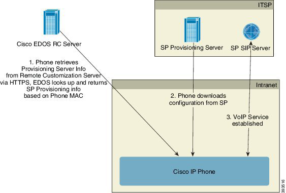
Page 49
phone's Customization State is set to Custom Pending. The phone then performs a resync URL command to
retrieve the Service Provider's configuration and, if successful, the Customization State is set to Acquired.
If queries either for local DHCP server or for EDOS server fails for provisioning, phone retries to onboard
over DHCP and EDOS.
If the Cisco EDOS RC Server does not have a service provider associated with the phone, the customization
state of the phone is set to Unavailable. The phone can be manually configured or an association added for
the service provider of the phone to the Cisco EDOS Server.
If a phone is provisioned via either the LCD or Web Configuration Utility, prior to the Customization State
becoming Acquired, the Customization State is set to Aborted and the Cisco EDOS Server will not be queried
unless the phone is factory reset.
Once the phone has been provisioned, the Cisco EDOS RC Server is not utilized unless the phone is factory
reset.
In-House Device Preprovisioning
With the Cisco factory default configuration, the phone automatically tries to resync to a profile on a TFTP
server. A managed DHCP server on a LAN delivers the information about the profile and TFTP server that
is configured for preprovisioning to the device. The service provider connects each new phone to the LAN.
The phone automatically resyncs to the local TFTP server and initializes its internal state in preparation for
deployment. This preprovisioning profile typically includes the URL of a remote provisioning server. The
provisioning server keeps the device updated after the device is deployed and connected to the customer
network.
The preprovisioned device bar code can be scanned to record its MAC address or serial number before the
phone is shipped to the customer. This information can be used to create the profile to which the phone
resynchronizes.
Cisco ATA 191 and ATA 192 Analog Telephone Adapter Provisioning Guide for Multiplatform Firmware
41
In-House Preprovisioning and Provisioning
In-House Device Preprovisioning
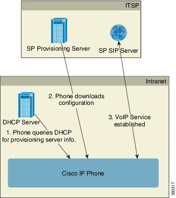
Page 50
Upon receiving the phone, the customer connects it to the broadband link. On power-up, the phone contacts
the provisioning server through the URL that is configured through preprovisioning. The phone can thus
resync and update the profile and firmware, as necessary.
Related Topics
Retail Distribution, on page 3
TFTP Provisioning, on page 42
Provisioning Server Setup
This section describes setup requirements for provisioning a phone by using various servers and different
scenarios. For the purposes of this document and for testing, provisioning servers are installed and run on a
local PC. Also, generally available software tools are useful for provisioning the phones.
TFTP Provisioning
The phones support TFTP for both provisioning resync and firmware upgrade operations. When devices are
deployed remotely, HTTPS is recommended, but HTTP and TFTP can also be used. This then requires
provisioning file encryption to add security, as it offers greater reliability, given NAT and router protection
mechanisms. TFTP is useful for the in-house preprovisioning of a large number of unprovisioned devices.
The phone is able to obtain a TFTP server IP address directly from the DHCP server through DHCP option
66. If a Profile_Rule is configured with the filepath of that TFTP server, the device downloads its profile from
the TFTP server. The download occurs when the device is connected to a LAN and powered up.
The Profile_Rule provided with the factory default configuration is ata$PSN.cfg, where $PSN represents the
product serial number.
For example, for ATA192-MPP, the filename is ata192.cfg.
For a device with the factory default profile, upon powering up, the device resyncs to this file on the local
TFTP server that DHCP option 66 specifies. The filepath is relative to the TFTP server virtual root directory.
Related Topics
In-House Device Preprovisioning, on page 41
Remote Endpoint Control and NAT
The phone is compatible with network address translation (NAT) to access the Internet through a router. For
enhanced security, the router might attempt to block unauthorized incoming packets by implementing symmetric
NAT, a packet-filtering strategy that severely restricts the packets that are allowed to enter the protected
network from the Internet. For this reason, remote provisioning by using TFTP is not recommended.
VoIP can coexist with NAT only when some form of NAT traversal is provided. Configure Simple Traversal
of UDP through NAT (STUN). This option requires that the user have:
• A dynamic external (public) IP address from your service
• A computer that is running STUN server software
• An edge device with an asymmetric NAT mechanism
Cisco ATA 191 and ATA 192 Analog Telephone Adapter Provisioning Guide for Multiplatform Firmware
42
In-House Preprovisioning and Provisioning
Provisioning Server Setup
Page 51
HTTP Provisioning
The phone behaves like a browser that requests web pages from a remote Internet site. This provides a reliable
means of reaching the provisioning server, even when a customer router implements symmetric NAT or other
protection mechanisms. HTTP and HTTPS work more reliably than TFTP in remote deployments, especially
when the deployed units are connected behind residential firewalls or NAT-enabled routers. HTTP and HTTPs
are used interchangeably in the following request type descriptions.
Basic HTTP-based provisioning relies on the HTTP GET method to retrieve configuration profiles. Typically,
a configuration file is created for each deployed phone, and these files are stored within an HTTP server
directory. When the server receives the GET request, it simply returns the file that is specified in the GET
request header.
Rather than a static profile, the configuration profile can be generated dynamically by querying a customer
database and producing the profile on-the-fly.
When the phone requests a resynch, it can use the HTTP POST method to request the resync configuration
data. The device can be configured to convey certain status and identification information to the server within
the body of the HTTP POST request. The server uses this information to generate a desired response
configuration profile, or to store the status information for later analysis and tracking.
As part of both GET and POST requests, the phone automatically includes basic identifying information in
the User-Agent field of the request header. This information conveys the manufacturer, product name, current
firmware version, and product serial number of the device.
The following example is the User-Agent request field from an ATA192-MPP:
User-Agent: Cisco/ATA192-MPP-11-1-0MPP-16(FCH2118DGQP)
User Agent is configurable, and the phone uses this the value if it has not be configured (still at default).
When the phone is configured to resync to a configuration profile by using HTTP, it is recommended that
HTTPS be used or the profile be encrypted to protect confidential information. Encrypted profiles that the
phone downloads by using HTTP avoid the danger of exposing confidential information that is contained in
the configuration profile. This resync mode produces a lower computational load on the provisioning server
when compared to using HTTPS.
The phone supports 256-bit AES in CBC mode to decrypt profiles.
The phones support HTTP Version 1.0, HTTP Version 1.1, and Chunk Encoding when HTTP Version 1.1 is
the negotiated transport protocol.
Note
HTTP Status Code Handling on Resync and Upgrade
The phone supports HTTP response for remote provisioning (Resync). Current phone behavior is categorized
in three ways:
• A—Success, where the “Resync Periodic” and “Resync Random Delay” values determine subsequent
requests.
• B—Failure when File Not Found or corrupt profile. The “Resync Error Retry Delay” value determines
subsequent requests.
Cisco ATA 191 and ATA 192 Analog Telephone Adapter Provisioning Guide for Multiplatform Firmware
43
In-House Preprovisioning and Provisioning
HTTP Provisioning

Page 52
• C—Other failure when a bad URL or IP address causes a connection error. The “Resync Error Retry
Delay” value determines subsequent requests.
Table 1: Phone Behavior for HTTP Responses
Phone Behavior
Description
HTTP Status Code
Retry request immediately with new
location.
This and future requests should be directed
to a new location.
301 Moved
Permanently
Retry request immediately with new
location.
Known as Temporarily Moved.
302 Found
C
Other 3xx responses not processed.
3xx
C
The request cannot be fulfilled due to bad
syntax.
400 Bad Request
Immediately retry request with
authentication credentials.
Maximum 2 retries. Upon failure,
the phone behavior is C.
Basic or digest access authentication
challenge.
401 Unauthorized
C
Server refuses to respond.
403 Forbidden
B
Requested resource not found. Subsequent
requests by client are permissible.
404 Not Found
Immediately retry request with
authentication credentials.
Maximum two retries. Upon failure,
the phone behavior is C.
Basic or digest access authentication
challenge.
407 Proxy
Authentication
Required
C
Other client error status codes are not
processed.
4xx
Phone behavior is C.
Generic error message.
500 Internal Server
Error
Phone behavior is C.
The server does not recognize the request
method, or it lacks the ability to fulfill the
request.
501 Not Implemented
Phone behavior is C.
The server is acting as a gateway or proxy
and receives an invalid response from the
upstream server.
502 Bad Gateway
Phone behavior is C.
The server is currently unavailable
(overloaded or down for maintenance). This
is a temporary state.
503 Service
Unavailable
C
The server behaves as a gateway or proxy and
does not receive timely response from the
upstream server.
504 Gateway Timeout
Cisco ATA 191 and ATA 192 Analog Telephone Adapter Provisioning Guide for Multiplatform Firmware
44
In-House Preprovisioning and Provisioning
HTTP Status Code Handling on Resync and Upgrade
Page 53
Phone Behavior
Description
HTTP Status Code
C
Other server error
5xx
HTTPS Provisioning
The phone supports HTTPS for provisioning for increased security in managing remotely deployed units.
Each phone carries a unique SLL Client Certificate (and associated private key), in addition to a Sipura CA
server root certificate. The latter allows the phone to recognize authorized provisioning servers, and reject
non-authorized servers. On the other hand, the client certificate allows the provisioning server to identify the
individual device that issues the request.
For a service provider to manage deployment by using HTTPS, a server certificate must be generated for each
provisioning server to which a phone resyncs by using HTTPS. The server certificate must be signed by the
Cisco Server CA Root Key, whose certificate is carried by all deployed units. To obtain a signed server
certificate, the service provider must forward a certificate signing request to Cisco, which signs and returns
the server certificate for installation on the provisioning server.
The provisioning server certificate must contain the Common Name (CN) field, and the FQDN of the host
running the server in the subject. It might optionally contain information following the host FQDN, separated
by a slash (/) character. The following examples are of CN entries that are accepted as valid by the phone:
CN=sprov.callme.com
CN=pv.telco.net/mailto:admin@telco.net
CN=prof.voice.com/info@voice.com
In addition to verifying the server certificate, the phone tests the server IP address against a DNS lookup of
the server name that is specified in the server certificate.
Get a Signed Server Certificate
The OpenSSL utility can generate a certificate signing request. The following example shows the openssl
command that produces a 1024-bit RSA public/private key pair and a certificate signing request:
openssl req –new –out provserver.csr
This command generates the server private key in privkey.pem and a corresponding certificate signing
request in provserver.csr. The service provider keeps the privkey.pem secret and submits
provserver.csr to Cisco for signing. Upon receiving the provserver.csr file, Cisco generates
provserver.crt, the signed server certificate.
Procedure
Step 1
Navigate to https://software.cisco.com/software/cda/home and log in with your CCO credentials.
Note
When a phone connects to a network for the first time or after a factory reset, and there are no DHCP options
set up, it contacts a device activation server for zero touch provisioning. New phones use “activate.cisco.com”
Cisco ATA 191 and ATA 192 Analog Telephone Adapter Provisioning Guide for Multiplatform Firmware
45
In-House Preprovisioning and Provisioning
HTTPS Provisioning
Page 54
instead of “webapps.cisco.com” for provisioning. Phones with firmware release earlier than 11.2(1) continues
to use “webapps.cisco.com”. We recommend that you allow both the domain names through your firewall.
Step 2
Select Certificate Management.
On the Sign CSR tab, the CSR of the previous step is uploaded for signing.
Step 3
From the Select Product drop-down list box, select SPA1xx firmware 1.3.3 and newer/SPA232D firmware
1.3.3 and newer/SPA5xx firmware 7.5.6 and newer/CP-78xx-3PCC/CP-88xx-3PCC.
Step 4
In the CSR File field, click Browse and select the CSR for signing.
Step 5
From the Sign in Duration drop-down list box, select the applicable duration (for example, 1 year).
Step 6
Click Sign Certificate Request.
Step 7
Select one of the following options to receive the signed certificate:
• Enter Recipient’s Email Address—If you wish to receive the certificate via email, enter your email
address in this field.
• Download—If you wish to download the signed certificate, select this option.
Step 8
Click Submit.
The signed server certificate is either emailed to the email address previously provided or downloaded.
Multiplatform Phone CA Client Root Certificate
Cisco also provides a Multiplatform Phone Client Root Certificate to the service provider. This root certificate
certifies the authenticity of the client certificate that each phone carries. The Multiplatform Phones also support
third-party signed certificates such as those provided by Verisign, Cybertrust, and so on.
The unique client certificate that each device offers during an HTTPS session carries identifying information
that is embedded in its subject field. This information can be made available by the HTTPS server to a CGI
script invoked to handle secure requests.
To determine if a phone carries an individualized certificate, use the $CCERT provisioning macro variable.
The variable value expands to either Installed or Not Installed, according to the presence or absence of a
unique client certificate. In the case of a generic certificate, it is possible to obtain the serial number of the
unit from the HTTP request header in the User-Agent field.
HTTPS servers can be configured to request SSL certificates from connecting clients. If enabled, the server
can use the Multiplatform Phone Client Root Certificate that Cisco supplies to verify the client certificate.
The server can then provide the certificate information to a CGI for further processing.
The location for certificate storage may vary. For example, in an Apache installation, the file paths for storage
of the provisioning server-signed certificate, its associated private key, and the Multiplatform Phone CA client
root certificate are as follows:
Server Certificate:
SSLCertificateFile /etc/httpd/conf/provserver.crt
Server Private Key:
SSLCertificateKeyFile /etc/httpd/conf/provserver.key
Certificate Authority (CA):
SSLCACertificateFile /etc/httpd/conf/spacroot.crt
Cisco ATA 191 and ATA 192 Analog Telephone Adapter Provisioning Guide for Multiplatform Firmware
46
In-House Preprovisioning and Provisioning
Multiplatform Phone CA Client Root Certificate
Page 55
For specific information, refer to the documentation for an HTTPS server.
The Cisco Client Certificate Root Authority signs each unique certificate. The corresponding root certificate
is made available to service providers for client authentication purposes.
Redundant Provisioning Servers
The provisioning server can be specified as an IP address or as a Fully Qualified Domain Name (FQDN). The
use of an FQDN facilitates the deployment of redundant provisioning servers. When the provisioning server
is identified through an FQDN, the phone attempts to resolve the FQDN to an IP address through DNS. Only
DNS A-records are supported for provisioning; DNS SRV address resolution is not available for provisioning.
The phone continues to process A-records until a server responds. If no server that is associated with the
A-records responds, the phone logs an error to the syslog server.
The ATA can associate with up to 10 DNS A-records for a DNS SRV record.
Syslog Server
If a syslog server is configured on the phone through use of the <Syslog Server> parameters, the resync and
upgrade operations send messages to the syslog server. A message can be generated at the start of a remote
file request (configuration profile or firmware load), and at the conclusion of the operation (indicating either
success or failure).
The logged messages are configured in the following parameters and macro expanded into the actual syslog
messages:
• Log_Resync_Request_Msg
• Log_Resync_Success_Msg
• Log_Resync_Failure_Msg
Cisco ATA 191 and ATA 192 Analog Telephone Adapter Provisioning Guide for Multiplatform Firmware
47
In-House Preprovisioning and Provisioning
Redundant Provisioning Servers
Page 56
Cisco ATA 191 and ATA 192 Analog Telephone Adapter Provisioning Guide for Multiplatform Firmware
48
In-House Preprovisioning and Provisioning
Syslog Server
Page 57
C H A P T E R 5
Provisioning Examples
• Provisioning Examples Overview, on page 49
• Basic Resync, on page 49
• Secure HTTPS Resync, on page 55
• Profile Management, on page 62
Provisioning Examples Overview
This chapter provides example procedures for transferring configuration profiles between the phone and the
provisioning server.
For information about creating configuration profiles, refer to Provisioning Formats, on page 13.
Basic Resync
This section demonstrates the basic resync functionality of the phones.
TFTP Resync
The phone supports multiple network protocols for retrieving configuration profiles. The most basic profile
transfer protocol is TFTP (RFC1350). TFTP is widely used for the provisioning of network devices within
private LAN networks. Although not recommended for the deployment of remote endpoints across the Internet,
TFTP can be convenient for deployment within small organizations, for in-house preprovisioning, and for
development and testing. See In-House Device Preprovisioning, on page 41 for more information on in-house
preprovisioning. In the following procedure, a profile is modified after downloading a file from a TFTP server.
Procedure
Step 1
Within a LAN environment, connect a PC and a phone to a hub, switch, or small router.
Step 2
Connect an analog phone to the Phone 1 port of the ATA
Step 3
On the PC, install and activate a TFTP server.
Step 4
Use a text editor to create a configuration profile that sets the value for GPP_A to 12345678 as shown in the
example.
Cisco ATA 191 and ATA 192 Analog Telephone Adapter Provisioning Guide for Multiplatform Firmware
49

Page 58
<flat-profile>
<GPP_A> 12345678
</GPP_A>
</flat-profile>
Step 5
Save the profile with the name basic.txt in the root directory of the TFTP server.
You can verify that the TFTP server is properly configured: request the basic.txt file by using a TFTP
client other than the phone. Preferably, use a TFTP client that is running on a separate host from the provisioning
server.
Step 6
Using an analog phone, obtain the IP address of the ATA (IVR menu **** 110 #).
If the configuration has been modified since it was manufactured, perform a factory reset on the phone by
using the IVR RESET option (**** 73738#).
Step 7
Open the PC web browser. For example, if the IP address of the device is 192.168.1.100:
http://192.168.1.100
Step 8
Select the Voice > Provisioning tab, and inspect the values of the general purpose parameters GPP_A through
GPP_P. These should be empty.
Step 9
Resync the test phone to the basic.txt configuration profile by opening the resync URL in a web browser
window.
If the IP address of the TFTP server is 192.168.1.200, the command should be similar to the following example:
http://192.168.1.100/admin/resync?tftp://192.168.1.200/basic.txt
When the phone receives this command, the device at address 192.168.1.100 requests the file basic.txt
from the TFTP server at IP address 192.168.1.200. The phone then parses the downloaded file and updates
the GPP_A parameter with the value 12345678.
Step 10
Verify that the parameter was correctly updated: Refresh the configuration page on the PC web browser and
select the Voice > Provisioning tab.
The GPP_A parameter should now contain the value 12345678.
Use Syslog to Log Messages
A phone can be configured to send logging messages to a syslog server over UDP, including messages related
to provisioning. This server is identified in the web server administration (Admin Login > Administration >
Log > Debug Log Settings, IPv4 Address field). Configure the syslog server IP address into the device and
observe the messages that are generated during the remaining procedures.
To get the information, you can access the phone Web interface, select Info > Debug Info > Control Logs
and click messages.
Cisco ATA 191 and ATA 192 Analog Telephone Adapter Provisioning Guide for Multiplatform Firmware
50
Provisioning Examples
Use Syslog to Log Messages
Page 59
Before you begin
Procedure
Step 1
Install and activate a syslog server on the local PC.
Step 2
Program the PC IP address into the Syslog_Server_IP parameter of the profile and submit the change:
<Syslog_Server_IP>192.168.1.210</Syslog_Server_IP>
Step 3
Click the System tab and enter the value of your local syslog server into the Syslog_Server parameter.
Step 4
Repeat the resync operation as described in TFTP Resync, on page 49.
The device generates two syslog messages during the resync. The first message indicates that a request is in
progress. The second message marks success or failure of the resync.
Step 5
Verify that your syslog server received messages similar to the following:
ATA192-MPP 00:0e:08:ab:cd:ef –- Successful resync tftp://192.168.1.200/basic.txt
The contents of these messages can be configured by using the following parameters:
• Log_Resync_Request_Msg
• Log_Resync_Success_Msg
• Log_Resync_Failure_Msg
If any of these parameters are cleared, the corresponding syslog message is not generated.
Resync a Device Automatically
A device can resync periodically to the provisioning server to ensure that any profile changes made on the
server are propagated to the endpoint device (as opposed to sending an explicit resync request to the endpoint).
To cause the phone to periodically resync to a server, a configuration profile URL is defined by using the
Profile_Rule parameter, and a resync period is defined by using the Resync_Periodic parameter.
Before you begin
Access the phone administration web page. See Access the Phone Web Interface, on page 36.
Procedure
Step 1
Select Voice > Provisioning.
Step 2
Define the Profile_Rule parameter. This example assumes a TFTP server IP address of 192.168.1.200.
Step 3
In the Resync Periodic field, enter a small value for testing, such as 30 seconds.
Cisco ATA 191 and ATA 192 Analog Telephone Adapter Provisioning Guide for Multiplatform Firmware
51
Provisioning Examples
Resync a Device Automatically
Page 60
Step 4
Click Submit all Changes.
With the new parameter settings, the phone resyncs twice a minute to the configuration file that the URL
specifies.
Step 5
Observe the resulting messages in the syslog trace (as described in the Use Syslog to Log Messages, on page
50 section).
Step 6
Ensure that the Resync On Reset field is set to Yes.
<Resync_On_Reset>Yes</Resync_On_Reset>
Step 7
Power cycle the phone to force it to resync to the provisioning server.
If the resync operation fails for any reason, such as if the server is not responding, the unit waits (for the
number of seconds configured in Resync Error Retry Delay) before it attempts to resync again. If Resync
Error Retry Delay is zero, the phone does not try to resync after a failed resync attempt.
Step 8
(Optional) Set the value of Resync Error Retry Delay field to a small number, such as 30.
<Resync_Error_Retry_Delay>30</Resync_Error_Retry_Delay>
Step 9
Disable the TFTP server, and observe the results in the syslog output.
Unique Profiles, Macro Expansion, and HTTP
In a deployment where each phone must be configured with distinct values for some parameters, such as
User_ID or Display_Name, the service provider can create a unique profile for each deployed device and host
those profiles on a provisioning server. Each phone, in turn, must be configured to resync to its own profile
according to a predetermined profile naming convention.
The profile URL syntax can include identifying information that is specific to each phone, such as MAC
address or serial number, by using the macro expansion of built-in variables. Macro expansion eliminates the
need to specify these values in multiple locations within each profile.
A profile rule undergoes macro expansion before the rule is applied to the phone. The macro expansion controls
a number of values, for example:
• $MA expands to the unit 12-digit MAC address (using lower case hex digits). For example, 000e08abcdef.
• $SN expands to the unit serial number. For example, 88012BA01234.
Other values can be macro expanded in this way, including all the general purpose parameters, GPP_A through
GPP_P. An example of this process can be seen in TFTP Resync, on page 49. Macro expansion is not limited
to the URL file name, but can also be applied to any portion of the profile rule parameter. These parameters
are referenced as $A through $P. For a complete list of variables that are available for macro expansion, see
Macro Expansion Variables, on page 72.
In this exercise, a profile specific to a phone is provisioned on a TFTP server.
Cisco ATA 191 and ATA 192 Analog Telephone Adapter Provisioning Guide for Multiplatform Firmware
52
Provisioning Examples
Unique Profiles, Macro Expansion, and HTTP
Page 61
Provision a Specific IP Phone Profile on a TFTP Server
Procedure
Step 1
Obtain the MAC address of the phone from its product label. (The MAC address is the number, using numbers
and lower–case hex digits, such as 000e08aabbcc.
Step 2
Copy the basic.txt configuration file (described in TFTP Resync, on page 49) to a new file named
ataxxxx.cfg (replacing xxxx with the macaddress with the MAC address of the phone).
Step 3
Move the new file in the virtual root directory of the TFTP server.
Step 4
Access the phone administration web page. See Access the Phone Web Interface, on page 36.
Step 5
Select Voice > Provisioning.
Step 6
Enter tftp://192.168.1.200/ata$MA.cfg in the Profile Rule field.
<Profile_Rule>
tftp://192.168.1.200/ata$MA.cfg
</Profile_Rule>
Step 7
Click Submit All Changes. This causes an immediate reboot and resync.
When the next resync occurs, the phone retrieves the new file by expanding the $MA macro expression into
its MAC address.
HTTP GET Resync
HTTP provides a more reliable resync mechanism than TFTP because HTTP establishes a TCP connection
and TFTP uses the less reliable UDP. In addition, HTTP servers offer improved filtering and logging features
compared to TFTP servers.
On the client side, the phone does not require any special configuration setting on the server to be able to
resync by using HTTP. The Profile_Rule parameter syntax for using HTTP with the GET method is similar
to the syntax that is used for TFTP. If a standard web browser can retrieve a profile from your HTTP server,
the phone should be able to do so as well.
Resync with HTTP GET
Procedure
Step 1
Install an HTTP server on the local PC or other accessible host.
The open source Apache server can be downloaded from the internet.
Step 2
Copy the basic.txt configuration profile (described in TFTP Resync, on page 49) onto the virtual root
directory of the installed server.
Step 3
To verify proper server installation and file access to basic.txt, access the profile with a web browser.
Step 4
Modify the Profile_Rule of the test phone to point to the HTTP server in place of the TFTP server, so as to
download its profile periodically.
Cisco ATA 191 and ATA 192 Analog Telephone Adapter Provisioning Guide for Multiplatform Firmware
53
Provisioning Examples
Provision a Specific IP Phone Profile on a TFTP Server
Page 62
For example, assuming the HTTP server is at 192.168.1.300, enter the following value:
<Profile_Rule>
http://192.168.1.200/basic.txt
</Profile_Rule>
Step 5
Click Submit All Changes. This causes an immediate reboot and resync.
Step 6
Observe the syslog messages that the phone sends. The periodic resyncs should now be obtaining the profile
from the HTTP server.
Step 7
In the HTTP server logs, observe how information that identifies the test phone appears in the log of user
agents.
This information should include the manufacturer, product name, current firmware version, and serial number.
Provisioning Through Cisco XML
For each of the phones, designated as xxxx here, you can provision through Cisco XML functions.
You can send an XML object to the phone by a SIP Notify packet or an HTTP Post to the CGI interface of
the phone: http://IPAddressPhone/CGI/Execute.
The CP-xxxx-3PCC extends the Cisco XML feature to support provisioning via an XML object:
<CP-xxxx-3PCCExecute>
<ExecuteItem URL=Resync:[profile-rule]/>
</CP-xxxx-3PCCExecute>
After the phone receives the XML object, it downloads the provisioning file from [profile-rule]. This rule
uses macros to simplify the development of the XML services application.
URL Resolution with Macro Expansion
Subdirectories with multiple profiles on the server provide a convenient method for managing a large number
of deployed devices. The profile URL can contain:
• A provisioning server name or an explicit IP address. If the profile identifies the provisioning server by
name, the phone performs a DNS lookup to resolve the name.
• A nonstandard server port that is specified in the URL by using the standard syntax :port following the
server name.
• The subdirectory of the server virtual root directory where the profile is stored, specified by using standard
URL notation and managed by macro expansion.
For example, the following Profile_Rule requests the profile file ($PN.cfg), in the server subdirectory
/cisco/config, from the TFTP server that is running on host prov.telco.com listening for a connection
on port 6900:
<Profile_Rule>
tftp://prov.telco.com:6900/cisco/config/$PN.cfg
</Profile_Rule>
Cisco ATA 191 and ATA 192 Analog Telephone Adapter Provisioning Guide for Multiplatform Firmware
54
Provisioning Examples
Provisioning Through Cisco XML
Page 63
A profile for each phone can be identified in a general purpose parameter, with its value referred within a
common profile rule by using macro expansion.
For example, assume GPP_B is defined as Dj6Lmp23Q.
The Profile_Rule has the value:
tftp://prov.telco.com/cisco/$B/$MA.cfg
When the device resyncs and the macros are expanded, the phone with a MAC address of 000e08012345
requests the profile with the name that contains the device MAC address at the following URL:
tftp://prov.telco.com/cisco/Dj6Lmp23Q/000e08012345.cfg
Secure HTTPS Resync
These mechanisms are available on the phone for resyncing by using a secure communication process:
• Basic HTTPS Resync
• HTTPS with Client Certificate Authentication
• HTTPS Client Filtering and Dynamic Content
Basic HTTPS Resync
HTTPS adds SSL to HTTP for remote provisioning so that the:
• The phone can authenticate the provisioning server.
• Provisioning server can authenticate the phone.
• Confidentiality of information exchanged between the phone and the provisioning server is ensured.
SSL generates and exchanges secret (symmetric) keys for each connection between the phone and the server,
using public/private key pairs that are pre-installed in the phone and the provisioning server.
On the client side, the phone does not require any special configuration setting on the server to be able to
resync using HTTPS. The Profile_Rule parameter syntax for using HTTPS with the GET method is similar
to the syntax that is used for HTTP or TFTP. If a standard web browser can retrieve a profile from a your
HTTPS server, the phone should be able to do so as well.
In addition to installing a HTTPS server, a SSL server certificate that Cisco signs must be installed on the
provisioning server. The devices cannot resync to a server that is using HTTPS unless the server supplies a
Cisco-signed server certificate. Instructions for creating signed SSL Certificates for Voice products can be
found at https://supportforums.cisco.com/docs/DOC-9852.
Related Topics
Secure HTTPS Resync, on page 55
Cisco ATA 191 and ATA 192 Analog Telephone Adapter Provisioning Guide for Multiplatform Firmware
55
Provisioning Examples
Secure HTTPS Resync
Page 64
Authenticate with Basic HTTPS Resync
Procedure
Step 1
Install an HTTPS server on a host whose IP address is known to the network DNS server through normal
hostname translation.
The open source Apache server can be configured to operate as an HTTPS server when installed with the
open source mod_ssl package.
Step 2
Generate a server Certificate Signing Request for the server. For this step, you might need to install the open
source OpenSSL package or equivalent software. If using OpenSSL, the command to generate the basic CSR
file is as follows:
openssl req –new –out provserver.csr
This command generates a public/private key pair, which is saved in the privkey.pem file.
Step 3
Submit the CSR file (provserver.csr) to Cisco for signing.
A signed server certificate is returned (provserver.cert) along with a Sipura CA Client Root Certificate,
spacroot.cert.
See https://supportforums.cisco.com/docs/DOC-9852 for more information
Step 4
Store the signed server certificate, the private key pair file, and the client root certificate in the appropriate
locations on the server.
In the case of an Apache installation on Linux, these locations are typically as follows:
Server Certificate:
SSLCertificateFile /etc/httpd/conf/provserver.cert
Server Private Key:
SSLCertificateKeyFile /etc/httpd/conf/pivkey.pem
Certificate Authority:
SSLCACertificateFile /etc/httpd/conf/spacroot.cert
Step 5
Restart the server.
Step 6
Copy the basic.txt configuration file (described in TFTP Resync, on page 49) onto the virtual root
directory of the HTTPS server.
Step 7
Verify proper server operation by downloading basic.txt from the HTTPS server by using a standard
browser from the local PC.
Step 8
Inspect the server certificate that the server supplies.
The browser probably does not recognize the certificate as valid unless the browser has been pre-configured
to accept Cisco as a root CA. However, the phones expect the certificate to be signed this way.
Modify the Profile_Rule of the test device to contain a reference to the HTTPS server, for example:
<Profile_Rule>
https://my.server.com/basic.txt
</Profile_Rule>
Cisco ATA 191 and ATA 192 Analog Telephone Adapter Provisioning Guide for Multiplatform Firmware
56
Provisioning Examples
Authenticate with Basic HTTPS Resync
Page 65
This example assumes the name of the HTTPS server is my.server.com.
Step 9
Click Submit All Changes.
Step 10
Observe the syslog trace that the phone sends.
The syslog message should indicate that the resync obtained the profile from the HTTPS server.
Step 11
(Optional) Use an Ethernet protocol analyzer on the phone subnet to verify that the packets are encrypted.
In this exercise, client certificate verification was not enabled. The connection between the phone and server
is encrypted. However, the transfer is not secure because any client can connect to the server and request the
file, given knowledge of the file name and directory location. For secure resync, the server must also authenticate
the client, as demonstrated in the exercise described in HTTPS with Client Certificate Authentication, on page
57.
HTTPS with Client Certificate Authentication
In the factory default configuration, the server does not request an SSL client certificate from a client. Transfer
of the profile is not secure because any client can connect to the server and request the profile. You can edit
the configuration to enable client authentication; the server requires a client certificate to authenticate the
phone before it accepts a connection request.
Because of this requirement, the resync operation cannot be independently tested by using a browser that
lacks the proper credentials. The SSL key exchange within the HTTPS connection between the test phone
and the server can be observed with the ssldump utility. The utility trace shows the interaction between client
and server.
Related Topics
Secure HTTPS Resync, on page 55
Authenticate HTTPS with Client Certificate
Procedure
Step 1
Enable client certificate authentication on the HTTPS server.
Step 2
In Apache (v.2), set the following in the server configuration file:
SSLVerifyClient
require
Also, ensure that the spacroot.cert has been stored as shown in the Basic HTTPS Resync, on page 55 exercise.
Step 3
Restart the HTTPS server and observe the syslog trace from the phone.
Each resync to the server now performs symmetric authentication, so that both the server certificate and the
client certificate are verified before the profile is transferred.
Step 4
Use ssldump to capture a resync connection between the phone and the HTTPS server.
Cisco ATA 191 and ATA 192 Analog Telephone Adapter Provisioning Guide for Multiplatform Firmware
57
Provisioning Examples
HTTPS with Client Certificate Authentication
Page 66
If client certificate verification is properly enabled on the server, the ssldump trace shows the symmetric
exchange of certificates (first server-to-client, then client-to-server) before the encrypted packets that contain
the profile.
With client authentication enabled, only a phone with a MAC address that matches a valid client certificate
can request the profile from the provisioning server. The server rejects a request from an ordinary browser or
other unauthorized device.
Configure a HTTPS Server for Client Filtering and Dynamic Content
If the HTTPS server is configured to require a client certificate, the information in the certificate identifies
the resyncing phone and supplies it with the correct configuration information.
The HTTPS server makes the certificate information available to CGI scripts (or compiled CGI programs)
that are invoked as part of the resync request. For the purpose of illustration, this exercise uses the open source
Perl scripting language, and assumes that Apache (v.2) is used as the HTTPS server.
Procedure
Step 1
Install Perl on the host that is running the HTTPS server.
Step 2
Generate the following Perl reflector script:
#!/usr/bin/perl -wT
use strict;
print “Content-Type: text/plain\n\n”;
print “<flat-profile><GPP_D>”;
print “OU=$ENV{‘SSL_CLIENT_I_DN_OU’},\n”;
print “L=$ENV{‘SSL_CLIENT_I_DN_L’},\n”;
print “S=$ENV{‘SSL_CLIENT_I_DN_S’}\n”;
print “</GPP_D></flat-profile>”;
Step 3
Save this file with the file name reflect.pl, with executable permission (chmod 755 on Linux), in the
CGI scripts directory of the HTTPS server.
Step 4
Verify accessibility of CGI scripts on the server (that is, /cgi-bin/…).
Step 5
Modify the Profile_Rule on the test device to resync to the reflector script, as in the following example:
https://prov.server.com/cgi-bin/reflect.pl?
Step 6
Click Submit All Changes.
Step 7
Observe the syslog trace to ensure a successful resync.
Step 8
Access the phone administration web page. See Access the Phone Web Interface, on page 36.
Step 9
Select Voice > Provisioning.
Step 10
Verify that the GPP_D parameter contains the information that the script captured.
This information contains the product name, MAC address, and serial number if the test device carries a
unique certificate from the manufacturer. The information contains generic strings if the unit was manufactured
before firmware release 2.0.
Cisco ATA 191 and ATA 192 Analog Telephone Adapter Provisioning Guide for Multiplatform Firmware
58
Provisioning Examples
Configure a HTTPS Server for Client Filtering and Dynamic Content
Page 67
A similar script can determine information about the resyncing device and then provide the device with
appropriate configuration parameter values.
HTTPS Certificates
The phone provides a reliable and secure provisioning strategy that is based on HTTPS requests from the
device to the provisioning server. Both a server certificate and a client certificate are used to authenticate the
phone to the server and the server to the phone.
In addition to Cisco issued certifications, the phone also accepts server certificates from a set of commonly
used SSL certificate providers.
To use HTTPS with the phone, you must generate a Certificate Signing Request (CSR) and submit it to Cisco.
The phone generates a certificate for installation on the provisioning server. The phone accepts the certificate
when it seeks to establish an HTTPS connection with the provisioning server.
HTTPS Methodology
HTTPS encrypts the communication between a client and a server, thus protecting the message contents from
other network devices. The encryption method for the body of the communication between a client and a
server is based on symmetric key cryptography. With symmetric key cryptography, a client and a server share
a single secret key over a secure channel that is protected by Public/Private key encryption.
Messages encrypted by the secret key can only be decrypted by using the same key. HTTPS supports a wide
range of symmetric encryption algorithms. The phone implements up to 256-bit symmetric encryption, using
the American Encryption Standard (AES), in addition to 128-bit RC4.
HTTPS also provides for the authentication of a server and a client engaged in a secure transaction. This
feature ensures that a provisioning server and an individual client cannot be spoofed by other devices on the
network. This capability is essential in the context of remote endpoint provisioning.
Server and client authentication is performed by using public/private key encryption with a certificate that
contains the public key. Text that is encrypted with a public key can be decrypted only by its corresponding
private key (and vice versa). The phone supports the Rivest-Shamir-Adleman (RSA) algorithm for public/private
key cryptography.
SSL Server Certificate
Each secure provisioning server is issued a secure sockets layer (SSL) server certificate that Cisco signs
directly. The firmware that runs on the phone recognizes only a Cisco certificate as valid. When a client
connects to a server by using HTTPS, it rejects any server certificate that is not signed by Cisco.
This mechanism protects the service provider from unauthorized access to the phone, or any attempt to spoof
the provisioning server. Without such protection, an attacker might be able to reprovision the phone, to gain
configuration information, or to use a different VoIP service. Without the private key that corresponds to a
valid server certificate, the attacker is unable to establish communication with a phone.
Cisco ATA 191 and ATA 192 Analog Telephone Adapter Provisioning Guide for Multiplatform Firmware
59
Provisioning Examples
HTTPS Certificates
Page 68
Obtain a Server Certificate
Procedure
Step 1
Contact a Cisco support person who will work with you on the certificate process. If you are not working with
a specific support person, email your request to ciscosb-certadmin@cisco.com.
Step 2
Generate a private key that will be used in a CSR (Certificate Signing Request). This key is private and you
do not need to provide this key to Cisco support. Use open source “openssl” to generate the key. For example:
openssl genrsa -out <file.key> 1024
Step 3
Generate a CSR that contains fields that identify your organization and location. For example:
openssl req -new -key <file.key> -out <file.csr>
You must have the following information:
• Subject field—Enter the Common Name (CN) that must be an FQDN (Fully Qualified Domain Name)
syntax. During SSL authentication handshake, the phone verifies that the certificate it receives is from
the machine that presented it.
• Server hostname—For example, provserv.domain.com.
• Email address—Enter an email address so that customer support can contact you if needed. This email
address is visible in the CSR.
Step 4
Email the CSR (in zip file format) to the Cisco support person or to ciscosb-certadmin@cisco.com. The
certificate is signed by Cisco. Cisco sends the certificate to you to install on your system.
Client Certificate
In addition to a direct attack on a phone, an attacker might attempt to contact a provisioning server through
a standard web browser or another HTTPS client to obtain the configuration profile from the provisioning
server. To prevent this kind of attack, each phone also carries a unique client certificate, signed by Cisco, that
includes identifying information about each individual endpoint. A certificate authority root certificate that
is capable of authenticating the device client certificate is given to each service provider. This authentication
path allows the provisioning server to reject unauthorized requests for configuration profiles.
Certificate Structure
The combination of a server certificate and a client certificate ensures secure communication between a remote
phone and its provisioning server. The figure below illustrates the relationship and placement of certificates,
public/private key pairs, and signing root authorities, among the Cisco client, the provisioning server, and the
certification authority.
The upper half of the diagram shows the Provisioning Server Root Authority that is used to sign the individual
provisioning server certificate. The corresponding root certificate is compiled into the firmware, which allows
the phone to authenticate authorized provisioning servers.
Cisco ATA 191 and ATA 192 Analog Telephone Adapter Provisioning Guide for Multiplatform Firmware
60
Provisioning Examples
Obtain a Server Certificate
Page 69
Figure 2: Certificate Authority Flow
Configure a Custom Certificate Authority
Digital certificates can be used to authenticate network devices and users on the network. They can be used
to negotiate IPSec sessions between network nodes.
A third party uses a Certificate Authority certificate to validate and authenticate two or more nodes that are
attempting to communicate. Each node has a public and private key. The public key encrypts data. The private
key decrypts data. Because the nodes have obtained their certificates from the same source, they are assured
of their respective identities.
The device can use digital certificates provided by a third-party Certificate Authority (CA) to authenticate
IPSec connections.
The phones support a set of preloaded Root Certificate Authority embedded in the firmware:
• Cisco Small Business CA Certificate
Cisco ATA 191 and ATA 192 Analog Telephone Adapter Provisioning Guide for Multiplatform Firmware
61
Provisioning Examples
Configure a Custom Certificate Authority
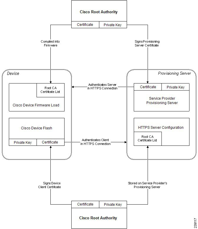
Page 70
• CyberTrust CA Certificate
• Verisign CA certificate
• Sipura Root CA Certificate
• Linksys Root CA Certificate
Before you begin
Access the phone administration web page. See Access the Phone Web Interface, on page 36.
Procedure
Step 1
Select Info > Status.
Step 2
Scroll to Custom CA Status and see the following fields:
• Custom CA Provisioning Status—Indicates the provisioning status.
• Last provisioning succeeded on mm/dd/yyyy HH:MM:SS; or
• Last provisioning failed on mm/dd/yyyy HH:MM:SS
• Custom CA Info—Displays information about the custom CA.
• Installed—Displays the “CN Value,” where “CN Value” is the value of the CN parameter for the
Subject field in the first certificate.
• Not Installed—Displays if no custom CA certificate is installed.
Profile Management
This section demonstrates the formation of configuration profiles in preparation for downloading. To explain
the functionality, TFTP from a local PC is used as the resync method, although HTTP or HTTPS can be used
as well.
Compress an Open Profile with Gzip
A configuration profile in XML format can become quite large if the profile specifies all parameters individually.
To reduce the load on the provisioning server, the phone supports compression of the XML file, by using the
deflate compression format that the gzip utility (RFC 1951) supports.
Compression must precede encryption for the phone to recognize a compressed and encrypted XML profile.
Note
Cisco ATA 191 and ATA 192 Analog Telephone Adapter Provisioning Guide for Multiplatform Firmware
62
Provisioning Examples
Profile Management

Page 71
For integration into customized back-end provisioning server solutions, the open source zlib compression
library can be used in place of the standalone gzip utility to perform the profile compression. However, the
phone expects the file to contain a valid gzip header.
Procedure
Step 1
Install gzip on the local PC.
Step 2
Compress the basic.txt configuration profile (described in TFTP Resync, on page 49) by invoking gzip
from the command line:
gzip basic.txt
This generates the deflated file basic.txt.gz.
Step 3
Save the basic.txt.gz file in the TFTP server virtual root directory.
Step 4
Modify the Profile_Rule on the test device to resync to the deflated file in place of the original XML file, as
shown in the following example:
tftp://192.168.1.200/basic.txt.gz
Step 5
Click Submit All Changes.
Step 6
Observe the syslog trace from the phone.
Upon resync, the phone downloads the new file and uses it to update its parameters.
Related Topics
Open Profile Compression, on page 17
Encrypt a Profile with OpenSSL
A compressed or uncompressed profile can be encrypted (however, a file must be compressed before it is
encrypted). Encryption is useful when the confidentiality of the profile information is of particular concern,
such as when TFTP or HTTP is used for communication between the phone and the provisioning server.
The phone supports symmetric key encryption by using the 256-bit AES algorithm. This encryption can be
performed by using the open source OpenSSL package.
Procedure
Step 1
Install OpenSSL on a local PC. This might require that the OpenSSL application be recompiled to enable
AES.
Step 2
Using the basic.txt configuration file (described in TFTP Resync, on page 49), generate an encrypted file
with the following command:
Cisco ATA 191 and ATA 192 Analog Telephone Adapter Provisioning Guide for Multiplatform Firmware
63
Provisioning Examples
Encrypt a Profile with OpenSSL
Page 72
openssl enc –aes-256-cbc –k MyOwnSecret –in basic.txt –out basic.cfg
The compressed basic.txt.gz file that was created in Compress an Open Profile with Gzip, on page 62
also can be used, because the XML profile can be both compressed and encrypted.
Step 3
Store the encrypted basic.cfg file in the TFTP server virtual root directory.
Step 4
Modify the Profile_Rule on the test device to resync to the encrypted file in place of the original XML file.
The encryption key is made known to the phone with the following URL option:
[--key MyOwnSecret ] tftp://192.168.1.200/basic.cfg
Step 5
Click Submit All Changes.
Step 6
Observe the syslog trace from the phone.
Upon resync, the phone downloads the new file and uses it to update its parameters.
Related Topics
AES-256-CBC Encryption, on page 18
Create Partitioned Profiles
A phone downloads multiple separate profiles during each resync. This practice allows management of different
kinds of profile information on separate servers and maintenance of common configuration parameter values
that are separate from account specific values.
Procedure
Step 1
Create a new XML profile, basic2.txt, that specifies a value for a parameter that makes it distinct from
the earlier exercises. For instance, to the basic.txt profile, add the following:
<GPP_B>ABCD</GPP_B>
Step 2
Store the basic2.txt profile in the virtual root directory of the TFTP server.
Step 3
Leave the first profile rule from the earlier exercises in the folder, but configure the second profile rule
(Profile_Rule_B) to point to the new file:
<Profile_Rule_B>tftp://192.168.1.200/basic2.txt
</Profile_Rule_B>
Step 4
Click Submit All Changes.
The phone now resyncs to both the first and second profiles, in that order, whenever a resync operation is
due.
Cisco ATA 191 and ATA 192 Analog Telephone Adapter Provisioning Guide for Multiplatform Firmware
64
Provisioning Examples
Create Partitioned Profiles
Page 73
Step 5
Observe the syslog trace to confirm the expected behavior.
Manage Provisioning with Parameter Name Aliases
When generating an XML profile for the ATA, it might be convenient to assign names to certain configuration
parameters that are different from the canonical names recognized by the ATA. For example, a customer
account database might generate XML element tags for a customer telephone number and SIP registration
password with names, such as SIP-number and SIP-password. These names can be mapped to the canonical
names (User_ID_1_ and Password_1_ ) before being applied to Line1.
In many instances, the back-end provisioning solution used by the service provider can perform this mapping.
However, the ATA itself can remap the parameter names internally. To do this, an alias map is defined and
stored in one of the general purpose provisioning parameters. Then, the profile rule which invokes the resync
is directed to remap the non-canonical XML elements as specified by the alias map.
Procedure
Step 1
Generate a profile named customer.XML containing the proprietary customeraccount XML form indicated
in the following example:
<customer-account>
<SIP-number> 17775551234</SIP-number>
<SIP-password> 512835907884</SIP-password>
</customer-account>
Step 2
Store the profile in the TFTP server virtual root directory.
Step 3
Open the web interface on the device to Voice > Provisioning, and edit GPP_A to contain the alias map. Do
not enter new lines through the web interface, instead simply enter each alias consecutively:
/customer-account/SIP-number = /flat-profile/User_ID_1_ ;
/customer-account/SIP-password = /flat-profile/Password_1_ ;
Step 4
Edit the Profile_Rule to point to the new XML profile, and specify the alias map as a URL option, as follows:
[--alias a ] tftp://192.168.1.200/customer.xml
Step 5
Click Submit All Changes.
When the ATA resyncs, it receives the XML profile, remaps the elements, as indicated by the alias map, and
populates the User_ID_1_ and Password_1_ parameters.
Step 6
View the Line 1 tab to verify the new configuration.
Note
The ATA supports alias remapping of a limited number of parameters. It is not meant to rename all parameters
in its configuration.
Cisco ATA 191 and ATA 192 Analog Telephone Adapter Provisioning Guide for Multiplatform Firmware
65
Provisioning Examples
Manage Provisioning with Parameter Name Aliases
Page 74
Cisco ATA 191 and ATA 192 Analog Telephone Adapter Provisioning Guide for Multiplatform Firmware
66
Provisioning Examples
Manage Provisioning with Parameter Name Aliases
Page 75
C H A P T E R 6
Provisioning Parameters
• Configuration Parameters Overview, on page 67
• Configuration Profile Parameters, on page 67
• Firmware Upgrade Parameters, on page 70
• General Purpose Parameters, on page 71
• Macro Expansion Variables, on page 72
• Internal Error Codes, on page 74
Configuration Parameters Overview
This chapter describes the provisioning parameters that can be used in configuration profile scripts.
Configuration Profile Parameters
The following table defines the function and usage of each parameter in the Configuration Profile Parameters
section under the Provisioning tab.
Description and Default Value
Parameter Name
Controls all resync actions independently of firmware upgrade actions.
Set to yes to enable remote provisioning.
The default value is Yes.
Provision_Enable
Triggers a resync after every reboot except for reboots caused by
parameter updates and firmware upgrades.
The default value is Yes.
Resync_On_Reset
Cisco ATA 191 and ATA 192 Analog Telephone Adapter Provisioning Guide for Multiplatform Firmware
67

Page 76
Description and Default Value
Parameter Name
Prevents an overload of the provisioning server when a large number
of devices power-on simultaneously and attempt initial configuration.
This delay is effective only on the initial configuration attempt, following
a device power-on or reset.
The parameter is the maximum time interval that the device waits before
making contact with the provisioning server. The actual delay is a
pseudo-random number between zero and this value.
This parameter is in units of 20 seconds; the default value of 3 represents
60 seconds. This feature is disabled when this parameter is set to zero.
The default value is 2 (40 seconds).
Resync_Random_Delay
The hour and minutes (HHmm) that the device resyncs with the
provisioning server.
The default value is empty. If the value is invalid, the parameter is
ignored. If this parameter is set with a valid value, the Resync_Periodic
parameter is ignored.
Resync At
Prevents an overload of the provisioning server when a large number
of devices power-on simultaneously.
To avoid flooding resync requests to the server from multiple phones,
the phone resyncs in the range between the hours and minutes, and the
hours and minutes plus the random delay (hhmm, hhmm+random_delay).
For example, if the random delay = (Resync_At_Random_Delay +
30)/60 minutes.
The input value in seconds is converted to minutes, rounding up to the
next minute to calculate the final random_delay interval.
This feature is disabled when this parameter is set to zero. The default
value is 600 seconds (10 minutes). If the parameter value is set to less
than 600, the default value is used.
Resync_At_Random_Delay
The time interval between periodic resyncs with the provisioning server.
The associated resync timer is active only after the first successful sync
with the server.
Set this parameter to zero to disable periodic resyncing.
The default value is 3600 seconds.
Resync_Periodic
Resync retry interval (in seconds) applied in case of resync failure.
The device has an error retry timer that activates if the previous attempt
to sync with the provisioning server fails. The device waits to contact
the server again until the timer counts down to zero.
This parameter is the value that is initially loaded into the error retry
timer. If this parameter is set to zero, the device does not try to resync
with the provisioning server following a failed attempt.
The default value is 3600 seconds.
Resync_Error_Retry_Delay
Cisco ATA 191 and ATA 192 Analog Telephone Adapter Provisioning Guide for Multiplatform Firmware
68
Provisioning Parameters
Configuration Profile Parameters
Page 77
Description and Default Value
Parameter Name
Maximum delay (in seconds) the ATA waits before performing a resync.
The device does not resync while one of its phone lines is active. Because
a resync can take several seconds, it is desirable to wait until the device
has been idle for an extended period before resyncing. This allows a
user to make calls in succession without interruption.
The device has a timer that begins counting down when all of its lines
become idle. This parameter is the initial value of the counter. Resync
events are delayed until this counter decrements to zero.
The default value is 14,400 seconds.
Forced_Resync_Delay
Enables a resync to be triggered via a SIP NOTIFY message.
The default value is Yes.
Resync_From_SIP
Triggers a resync after every firmware upgrade attempt.
The default value is Yes.
Resync_After_Upgrade_Attempt
Configurable resync trigger conditions. A resync is triggered when the
logic equation in these parameters evaluates to TRUE.
The default value is (empty).
Resync_Trigger_1,
Resync_Trigger_2
Determines whether a file-not-found response from the provisioning
server constitutes a successful or a failed resync.
A failed resync activates the error resync timer.
The default value is Yes.
Resync_Fails_On_FNF
Determines whether to check the Subject Alternative Name (SAN) for
the HTTPS provisioning. Set to yes to enable the SAN check.
The default value is Yes.
HTTPS_Name_Validate
This parameter is a profile script that evaluates to the provisioning resync
command. The command specifies the protocol (TFTP, HTTP, or
HTTPS) and an associated URL.
If the command is not specified, TFTP is assumed, and the address of
the TFTP server is obtained through DHCP option 66.
In the URL, either the IP address or the FQDN of the server can be
specified. The file name can have macros, such as $MA, which expands
to the device MAC address.
The default value is /ata$PSN.cfg.
Profile_Rule
Cisco ATA 191 and ATA 192 Analog Telephone Adapter Provisioning Guide for Multiplatform Firmware
69
Provisioning Parameters
Configuration Profile Parameters
Page 78
Description and Default Value
Parameter Name
Defines second, third, and fourth resync commands and associated
profile URLs.
These profile scripts are executed sequentially after the primary Profile
Rule resync operation has completed. If a resync is triggered and Profile
Rule is blank, Profile Rule B, C, and D are still evaluated and executed.
The default value is (empty).
Profile_Rule_B, Profile_Rule_C,
Profile_Rule_D
This parameter contains the message that is sent to the syslog server at
the start of a resync attempt.
The default value is $PN $MAC –Requesting resync
$SCHEME://$SERVIP:$PORT$PATH.
Log_Resync_Request_Msg
The syslog message that is issued upon successful completion of a resync
attempt.
The default value is $PN $MAC –Successful resync
$SCHEME://$SERVIP:$PORT$PATH -- $ERR.
Log_Resync_Success_Msg
The syslog message that is issued after a failed resync attempt.
The default value is $PN $MAC – Resyncfailed: $ERR.
Log_Resync_Failure_Msg
The target URL to which configuration reports are sent. This parameter
has the same syntax as the Profile_Rule parameter, and resolves to a
TCP/IP command with an associated URL.
A configuration report is generated in response to an authenticated SIP
NOTIFY message, with Event: report. The report is an XML file
containing the name and value of all the device parameters.
This parameter may optionally contain an encryption key.
For example: [ --key $K ] tftp://ps.callhome.net/$MA/rep.xml.enc
Report_Rule
Firmware Upgrade Parameters
The following table defines the function and usage of each parameter in the Firmware Upgrade section of the
Provisioning tab.
Description and Default Value
Parameter Name
Enables firmware upgrade operations independently of resync actions.
The default value is Yes.
Upgrade_Enable
Cisco ATA 191 and ATA 192 Analog Telephone Adapter Provisioning Guide for Multiplatform Firmware
70
Provisioning Parameters
Firmware Upgrade Parameters
Page 79
Description and Default Value
Parameter Name
The upgrade retry interval (in seconds) applied in case of upgrade failure.
The device has a firmware upgrade error timer that activates after a
failed firmware upgrade attempt. The timer is initialized with the value
in this parameter. The next firmware upgrade attempt occurs when this
timer counts down to zero.
The default value is 3600 seconds.
Upgrade_Error_Retry_Delay
Enforces a lower limit on the acceptable version number during a
firmware upgrade or downgrade. The device does not complete a
firmware upgrade operation unless the firmware version is greater than
or equal to this parameter.
The default value is (empty).
Downgrade_Rev_Limit
This parameter is a firmware upgrade script with the same syntax as
Profile_Rule. Defines upgrade conditions and associated firmware URLs.
The default value is (empty).
Upgrade_Rule
The syslog message that is issued at the start of a firmware upgrade
attempt.
The default value is $PN $MAC – Requesting upgrade
$SCHEME://$SERVIP:$PORT$PATH.
Log_Upgrade_Request_Msg
The syslog message that is issued after a firmware upgrade attempt
completes successfully.
The default value is $PN $MAC – Successful upgrade
$SCHEME://$SERVIP:$PORT$PATH --$ERR.
Log_Upgrade_Success_Msg
The syslog message that is issued after a failed firmware upgrade attempt.
The default value is $PN $MAC – Upgrade failed: $ERR.
Log_Upgrade_Failure_Msg
General Purpose Parameters
The following table defines the function and usage of each parameter in the General Purpose Parameters
section of the Provisioning tab.
Description and Default Value
Parameter Name
Special purpose provisioning parameters, designed to hold encryption
keys and passwords. To ensure the integrity of the encryption
mechanism, these parameters must be kept secret. Therefore these
parameters are not displayed on the device configuration web page, and
they are not included in the configuration report sent in response to a
SIP NOTIFY command.
The default value is (empty).
GPP_SA, GPP_SB, GPP_SC,
GPP_SD
Cisco ATA 191 and ATA 192 Analog Telephone Adapter Provisioning Guide for Multiplatform Firmware
71
Provisioning Parameters
General Purpose Parameters
Page 80
Description and Default Value
Parameter Name
General purpose provisioning parameters.
These parameters can be used as variables in provisioning and upgrade
rules. They are referenced by prepending the variable name with a ‘$’
character, such as $A for GPP_A.
The default value is (empty).
GPP_A through GPP_P
Macro Expansion Variables
Certain macro variables are recognized within the following provisioning parameters:
• Profile_Rule
• Profile_Rule_*
• Resync_Trigger_*
• Upgrade_Rule
• Log_*
• GPP_* (under specific conditions)
Within these parameters, syntax types, such as $NAME or $(NAME), are recognized and expanded.
Macro variable substrings can be specified with the notation $(NAME:p) and $(NAME:p:q), where p and q
are non-negative integers (available in revision 2.0.11 and above). The resulting macro expansion is the
substring starting at character offset p, with length q (or else till end-of-string if q is not specified). For example,
if GPP_A contains ABCDEF, then $(A:2) expands to CDEF, and $(A:2:3) expands to CDE.
An unrecognized name is not translated, and the $NAME or $(NAME) form remains unchanged in the
parameter value after expansion.
Description and Default Value
Parameter Name
The form $$ expands to a single $ character.
$
Replaced by the contents of the general purpose parameters GPP_A
through GPP_P.
A through P
Replaced by special purpose parameters GPP_SA through GPP_SD.
These parameters hold keys or passwords used in provisioning.
Note
$SA through $SD are recognized as arguments to the optional resync
URL qualifier, --key.
SA through SD
MAC address using lower case hex digits, for example, 000e08aabbcc.
MA
MAC address using upper case hex digits, for example
000E08AABBCC.
MAU
Cisco ATA 191 and ATA 192 Analog Telephone Adapter Provisioning Guide for Multiplatform Firmware
72
Provisioning Parameters
Macro Expansion Variables
Page 81
Description and Default Value
Parameter Name
MAC address using lower case hex digits, and colons to separate hex
digit pairs. For example 00:0e:08:aa:bb:cc.
MAC
Product name. For example, ATA191-MPP.
PN
Product Series Number. For example, 191
PSN
Serial Number string. for example 88012BA01234.
SN
SSL Client Certificate status: Installed or Not Installed.
CCERT
IP address of the phone within its local subnet. For example
192.168.1.100.
IP
External IP of the phone, as seen on the Internet. For example
66.43.16.52.
EXTIP
Software version string. For example,
Software version string. For example, 11-1-0MPP-19
SWVER
Hardware version string. For example, 4
HWVER
Provisioning State (a numeric string):
-1 = explicit resync request
0 = power-up resync
1 = periodic resync
2 = resync failed, retry attempt
PRVST
Upgrade State (a numeric string):
1 = first upgrade attempt
2 = upgrade failed, retry attempt
UPGST
Result message (ERR) of previous upgrade attempt; for example http_get
failed.
UPGERR
Seconds since last resync attempt.
PRVTMR
Seconds since last upgrade attempt.
UPGTMR
Seconds since Line 1 lost registration with SIP server.
REGTMR1
Seconds since Line 2 lost registration with SIP server.
REGTMR2
Legacy macro name.
UPGCOND
File access scheme, one of TFTP, HTTP, or HTTPS, as obtained after
parsing resync or upgrade URL.
SCHEME
Cisco ATA 191 and ATA 192 Analog Telephone Adapter Provisioning Guide for Multiplatform Firmware
73
Provisioning Parameters
Macro Expansion Variables
Page 82
Description and Default Value
Parameter Name
Request target server host name, as obtained after parsing resync or
upgrade URL.
SERV
Request target server IP address, as obtained after parsing resync or
upgrade URL, possibly following DNS lookup.
SERVIP
Request target UDP/TCP port, as obtained after parsing resync or
upgrade URL.
PORT
Request target file path, as obtained after parsing resync or upgrade
URL.
PATH
Result message of resync or upgrade attempt. Only useful in generating
result syslog messages. The value is preserved in the UPGERR variable
in the case of upgrade attempts.
ERR
The contents of the Line n UserID configuration parameter.
UIDn
Controls whether the phone needs to request for a license.
Values for
ORIGTYPE
are: orig_ent, orig_mpp, none
Values for
AUTHSTATUS
are: classic, wxc, none
Add the variables in:
• profile rule or upgrade rule macro expansion and conditional
expression
• transition authorization rule macro expansion
ORIGTYPE
AUTHSTATUS
Internal Error Codes
The ATA defines a number of internal error codes (X00–X99) to facilitate configuration in providing finer
control over the behavior of the unit under certain error conditions.
Description and Default Value
Parameter Name
Transport layer (or ICMP) error when sending a SIP request.
X00
SIP request times out while waiting for a response.
X20
General SIP protocol error (for example, unacceptable codec in SDP in
200 and ACK messages, or times out while waiting for ACK).
X40
Dialed number invalid according to given dial plan.
X60
Cisco ATA 191 and ATA 192 Analog Telephone Adapter Provisioning Guide for Multiplatform Firmware
74
Provisioning Parameters
Internal Error Codes
Page 83
C H A P T E R 7
Voice Parameters
• Voice Parameter Numbering, on page 75
• Voice Parameters, on page 75
Voice Parameter Numbering
Certain types of parameters apply to multiple elements, such as users and lines. In the configuration file, the
parameter name is appended with a number, such as <Line_Enable_1> and <Line_Enable_2>. To understand
this numbering system, use the following key:
• 1—User 1 or Line1 (PHONE1 port)
• 2—User 2 or Line 2 (PHONE2 port)
FXS port 1 uses <Proxy_1_>
FXS port 2 used <Proxy_2_>
Voice Parameters
Domain of the service provider to which the ATA is connected to. It prevents the ATA from
connecting to other service providers.
<Restricted_Access_Domains>
This feature is not available in ATA web voice.
<Enable_Web_Admin_Access>
Password for the administrator to manage the ATA by using the built-in IVR through a connected
phone.
<IVR_Admin_Password>
The number of seconds of delay between restarting the voice module and initializing network
interface.
Default setting—3
<Network_Startup_Delay>
In DNS packages, the server will suggest a TTL value to the client; if this parameter is set to yes,
the value from the server will be ignored.
Default setting—Yes
<DNS_Query_TTL_Ignore>
Cisco ATA 191 and ATA 192 Analog Telephone Adapter Provisioning Guide for Multiplatform Firmware
75

Page 84
Determines whether the ATA will always register to the Local Survivability Gateway (LSG) nodes
even though the Webex Calling Session Signaling Engine (SSE) nodes are reachable.
This test mode is used to verify the functions of the LSG nodes.
Default setting—No
<Survivability_Test_Mode>
To enable the Federal Information Processing Standards (FIPS 140-2) mode on the ATA to meet
the security requirements for cryptographic modules. Allowed values are Disabled and Enabled.
Default setting—Disabled
<FIPS_Mode>
Select the minimum protocol version for the TLS connections.
Allowed values: TLS 1.0, TLS 1.1, TLS 1.2, and TLS 1.3.
Default setting—TLS 1.1
<TLS_Min_Version>
Controls all resync actions independently of firmware upgrade actions. Set to yes to enable remote
provisioning.
Default setting—Yes
<Provision_Enable>
Triggers a resync after every reboot except for reboots caused by parameter updates and firmware
upgrades.
Default setting—Yes
<Resync_On_Reset>
The maximum value for a random time interval that the ATA waits before making its initial contact
with the provisioning server. This delay is effective only on the initial configuration attempt
following power-on or reset. The delay is a pseudorandom number between zero and this value.
This parameter is in units of 20 seconds; the default value of 2 represents 40 seconds.
This feature is disabled when this parameter is set to zero. This feature can be used to prevent an
overload of the provisioning server when a large number of devices power-on simultaneously.
Default setting—2 (40 seconds)
<Resync_Random_Delay>
The time of day when the device tries to resync. The resync is performed each day. Used in
conjunction with the Resync At Random Delay.
Default setting—blank
<Resync_At_HHmm>
Used in conjunction with the Resync At (HHmm) setting, this parameter sets a range of possible
values for the resync delay. The system randomly chooses a value from this range and waits the
specified number of seconds before attempting to resync. This feature is intended to prevent the
network jam that would occur if all resynchronizing devices began the resync at the exact same
time of day.
Default setting—600
<Resync_At_Random_Delay>
The time interval between periodic resyncs with the provisioning server. The associated resync
timer is active only after the first successful synchronization with the server. Setting this parameter
to zero disables periodic resynchronization.
Default setting—3600 seconds
<Resync_Periodic>
Cisco ATA 191 and ATA 192 Analog Telephone Adapter Provisioning Guide for Multiplatform Firmware
76
Voice Parameters
Voice Parameters
Page 85
Resync retry interval (in seconds) applied in case of resync failure. The ATA has an error retry
timer that activates if the previous attempt to sync with the provisioning server fails. The ATA
waits to contact the server again until the timer counts down to zero. This parameter is the value
that is initially loaded into the error retry timer. If this parameter is set to zero, the ATA does not
try to resync with the provisioning server following a failed attempt.
Default setting—3600 seconds
<Resync_Error_Retry_Delay>
Maximum delay (in seconds) that the ATA waits before performing a resync. The ATA does not
resync while one of its lines is active. Because a resync can take several seconds, it is desirable to
wait until the ATA has been idle for an extended period before resynchronizing. This allows a user
to make calls in succession without interruption. The ATA has a timer that begins counting down
when all of its lines become idle. This parameter is the initial value of the counter.
Resync events are delayed until this counter decrements to zero.
Default setting—14400 seconds
<Forced_Resync_Delay>
Enables a resync to be triggered via a SIP NOTIFY message.
Default setting—yes
<Resync_From_SIP>
Triggers a resync after every firmware upgrade attempt.
Default setting—Yes
<Resync_After_Upgrade_Attempt>
Configurable resync trigger conditions. A resync is triggered when the logic equation in these
parameters evaluates to TRUE.
Default setting—blank
<Resync_Trigger_1>
<Resync_Trigger_2>
Determines whether a file-not-found response from the provisioning server constitutes a successful
or a failed resync.
A failed resync activates the error resync timer.
Default setting—Yes
<Resync_Fails_On_FNF>
This parameter is a profile script that evaluates to the provisioning resync command. The command
is a TCP/IP operation and an associated URL. The TCP/IP operation can be TFTP, HTTP, or
HTTPS. If the command is not specified, TFTP is assumed, and the address of the TFTP server is
obtained through DHCP option 66.
In the URL, either the IP address or the FQDN of the server can be specified. The file name can
have macros, such as $MA, which expands to the ATA MAC address.
Default setting—/ata$PSN.cfg
<Profile_Rule>
Defines second, third, and fourth resync commands and associated profile URLs.
These profile scripts are executed sequentially after the primary Profile Rule resync operation has
completed. If a resync is triggered and Profile Rule is blank, Profile Rule B, C, and D are still
evaluated and executed.
Default setting—blank
<Profile_Rule_B>
<Profile_Rule_C>
<Profile_Rule_D>
This parameter contains the message that is sent to the Syslog server at the start of a resync attempt.
Default setting—$PN $MAC – Requesting resync $SCHEME://$SERVIP:$PORT$PATH
<Log_Resync_Request_Msg>
Cisco ATA 191 and ATA 192 Analog Telephone Adapter Provisioning Guide for Multiplatform Firmware
77
Voice Parameters
Voice Parameters
Page 86
Syslog message issued upon successful completion of a resync attempt.
Default setting—$PN $MAC – Successful resync $SCHEME://$SERVIP:$PORT$PATH
<Log_Resync_Success_Msg>
Syslog message issued after a failed resync attempt.
Default setting—$PN $MAC -- Resync failed: $ERR
<Log_Resync_Failure_Msg>
The target URL to which configuration reports are sent. This parameter has the same syntax as the
Profile_Rule parameter, and resolves to a TCP/IP command with an associated URL.
A configuration report is generated in response to an authenticated SIP NOTIFY message, with
Event: report. The report is an XML file containing the name and value of all the device parameters.
This parameter may optionally contain an encryption key.
For example:
[ --key $K ] tftp://ps.callhome.net/$MA/rep.xml.enc
Default setting—blank
<Report_Rule>
Determines whether or not firmware upgrade operations can occur independently of resync actions.
Default setting—Yes
<Upgrade_Enable>
The upgrade retry interval (in seconds) applied in case of upgrade failure. The ATA has a firmware
upgrade error timer that activates after a failed firmware upgrade attempt. The timer is initialized
with the value in this parameter. The next firmware upgrade attempt occurs when this timer counts
down to zero.
Default setting—3600 seconds
<Upgrade_Error_Retry_Delay>
Enforces a lower limit on the acceptable version number during a firmware upgrade or downgrade.
The ATA does not complete a firmware upgrade operation unless the firmware version is greater
than or equal to this parameter.
Default setting—blank
<Downgrade_Rev_Limit>
This parameter is a firmware upgrade script with the same syntax as Profile_Rule. Defines upgrade
conditions and associated firmware URLs.
Default setting—blank
<Upgrade_Rule>
Syslog message issued at the start of a firmware upgrade attempt.
Default setting—$PN $MAC – Requesting upgrade $SCHEME://$SERVIP:$PORT$PATH
<Log_Upgrade_Request_Msg>
Syslog message issued after a firmware upgrade attempt completes successfully.
Default setting—$PN $MAC – Successful upgrade $SCHEME://$SERVIP:$PORT$PATH --
$ERR
<Log_Upgrade_Success_Msg>
Syslog message issued after a failed firmware upgrade attempt.
Default setting—$PN $MAC – Upgrade failed: $ERR
<Log_Upgrade_Failure_Msg>
This field is not currently used.
<License_Keys>
Cisco ATA 191 and ATA 192 Analog Telephone Adapter Provisioning Guide for Multiplatform Firmware
78
Voice Parameters
Voice Parameters
Page 87
The URL of a file location for a custom Certificate Authority (CA) certificate. Either the IP address
or the FQDN of the server can be specified. The file name can have macros, such as $MA, which
expands to the ATA MAC address.
Default setting—blank
<Custom_CA_URL>
General purpose provisioning parameters. These parameters can be used as variables in provisioning
and upgrade rules. They are referenced by prepending the variable name with a ‘$’ character, such
as $A for GPP_A.
Default setting—blank
<GPP_A> to <GPP_P>
The two-letter upper-case macro names SA through SD identify GPP_SA through GPP_SD as a
special case when used as arguments of the key URL option.
<GPP_SA> to <GPP_SD>
Controls whether to enable the MIC certificate renewal procedure.
Default setting—No
<MIC_Cert_Refresh_Enable>
HTTP URL for requesting the renewed MIC certificate from the SUDI server.
Default setting—http://sudirenewal.cisco.com/
<MIC_Cert_Refresh_Rule>
The maximum times a call can be forwarded. The valid range is from 1 to 255.
Default setting—70
<Max_Forward>
Number of times an invite can be redirected to avoid an infinite loop.
Default setting—5.
<Max_Redirection>
The maximum number of times (from 0 to 255) a request may be challenged.
Default setting—2
<Max_Auth>
The User-Agent header used in outbound requests. If empty, the header is not included. Macro
expansion of $A to $D corresponding to GPP_A to GPP_D allowed.
Default setting—$VERSION
<SIP_User_Agent_Name>
The server header used in responses to inbound responses.
Default setting—$VERSION
<SIP_Server_Name>
The User-Agent name to be used in a REGISTER request. If this value is not specified, the SIP
User Agent Name parameter is also used for the REGISTER request.
Default setting—blank
<SIP_Reg_User_Agent_Name>
Accept-Language header used. There is no default (this indicates that the ATA does not include
this header) If empty, the header is not included.
Default setting—blank
<SIP_Accept_Language>
The MIME Type used in a SIP INFO message to signal a DTMF event.
Default setting—application/dtmf-relay.
<DTMF_Relay_MIME_Type>
Cisco ATA 191 and ATA 192 Analog Telephone Adapter Provisioning Guide for Multiplatform Firmware
79
Voice Parameters
Voice Parameters
Page 88
The MIME Type used in a SIP INFO message to signal a hook flash event.
Default setting—application/hook-flash
<Hook_Flash_MIME_Type>
Determines whether or not the ATA removes the last registration before submitting a new one, if
the value is different. Select yes to remove the last registration, or select no to omit this step.
Default setting—no
<Remove_Last_Reg>
Determines whether or not the ATA uses compact SIP headers in outbound SIP messages. Select
yes or no from the dropdown list. Select yes to use compact SIP headers in outbound SIP messages.
Select no to use normal SIP headers. If inbound SIP requests contain compact headers, the ATA
reuses the same compact headers when generating the response regardless the settings of the Use
Compact Header parameter. If inbound SIP requests contain normal headers, the ATA substitutes
those headers with compact headers (if defined by RFC 261) if Use Compact Header parameter is
set to yes.
Default setting—no
<Use_Compact_Header>
Determines whether or not the Display Name is private. Select yes if you want the ATA to enclose
the string (configured in the Display Name) in a pair of double quotes for outbound SIP messages.
If the display name includes " or , these will be escaped to " and \ within the double quotes.
Otherwise, select no.
Default setting—no
<Escape_Display_Name>
Configures the type of call hold: a:sendonly or 0.0.0.0. Do not use the 0.0.0.0 syntax in a HOLD
SDP; use the a:sendonly syntax.
Default setting—no
<RFC_2543_Call_Hold>
Select yes if you want all AVT tone packets (encoded for redundancy) to have the marker bit set
for each DTMF event. Select no to have the marker bit set only for the first packet.
Default setting—yes
<Mark_all_AVT_Packets>
The lowest TCP port number that can be used for SIP sessions.
Default setting—5060
<SIP_TCP_Port_Min>
The highest TCP port number that can be used for SIP sessions.
Default setting—5080
<SIP_TCP_Port_Max>
Enables or disables the Computer Telephone Interface feature provided by some servers.
Default setting—no
<CTI_Enable>
RFC 3261 T1 value (round-trip time estimate), which can range from 0 to 64 seconds.
Default setting—0.5
<SIP_T1>
RFC 3261 T2 value (maximum retransmit interval for non-INVITE requests and INVITE responses),
which can range from 0 to 64 seconds.
Default setting—4
<SIP_T2>
Cisco ATA 191 and ATA 192 Analog Telephone Adapter Provisioning Guide for Multiplatform Firmware
80
Voice Parameters
Voice Parameters
Page 89
RFC 3261 T4 value (maximum duration a message remains in the network), which can range from
0 to 64 seconds.
Default setting—5
<SIP_T4>
INVITE time-out value, which can range from 0 to 64 seconds.
Default setting—32
<SIP_Timer_B>
Non-INVITE time-out value, which can range from 0 to 64 seconds.
Default setting—32
<SIP_Timer_F>
H INVITE final response, time-out value, which can range from 0 to 64 seconds.
Default setting—32
<SIP_Timer_H>
ACK hang-around time, which can range from 0 to 64 seconds.
Default setting—32
<SIP_Timer_D>
Non-INVITE response hang-around time, which can range from 0 to 64 seconds.
Default setting—32
<SIP_Timer_J>
INVITE request Expires header value. If you enter 0, the Expires header is not included in the
request. Range: 0–(231–1)
Default setting—240
<INVITE_Expires>
ReINVITE request Expires header value. If you enter 0, the Expires header is not included in the
request. Range: 0–(231–1)
Default setting—30
<ReINVITE_Expires>
Minimum registration expiration time allowed from the proxy in the Expires header or as a Contact
header parameter. If the proxy returns a value less than this setting, the minimum value is used.
Default setting—1
<Reg_Min_Expires>
Maximum registration expiration time allowed from the proxy in the Min-Expires header. If the
value is larger than this setting, the maximum value is used.
Default setting—7200
<Reg_Max_Expires>
Interval to wait before the ATA retries registration after failing during the last registration.
Default setting—30
<Reg_Retry_Intvl>
When registration fails with a SIP response code that does not match Retry Reg RSC, the ATA
waits for the specified length of time before retrying. If this interval is 0, the ATA stops trying.
This value should be much larger than the Reg Retry Intvl value, which should not be 0.
Default setting—1200
<Reg_Retry_Long_Intvl>
Random delay range (in seconds) to add to Register Retry Intvl when retrying REGISTER after a
failure.
Default setting—0 (disabled)
<Reg_Retry_Random_Delay>
Cisco ATA 191 and ATA 192 Analog Telephone Adapter Provisioning Guide for Multiplatform Firmware
81
Voice Parameters
Voice Parameters
Page 90
Random delay range (in seconds) to add to Register Retry Long Intvl when retrying REGISTER
after a failure.
Default setting—0 (disabled)
<Reg_Retry_Long_Random_Delay>
The maximum value to cap the exponential back-off retry delay (which starts at Register Retry
Intvl and doubles on every REGISTER retry after a failure) In other words, the retry interval is
always at Register Retry Intvl seconds after a failure. If this feature is enabled, Reg Retry Random
Delay is added on top of the exponential back-off adjusted delay value.
Default setting—0, which disables the exponential backoff
<Reg_Retry_Intvl_Cap>
SIP response status code for the corresponding Special Information Tone (SIT), SIT1 through
SIT4. For example, if you set the SIT1 RSC to 404, when the user makes a call and a failure code
of 404 is returned, the SIT1 tone is played. Reorder or Busy tone is played by default for all
unsuccessful response status code for SIT 1 RSC through SIT 4 RSC.
Default setting—blank
<SIT1_RSC>
<SIT2_RSC>
<SIT3_RSC>
<SIT4_RSC>
SIP response code that retries a backup server for the current request.
Default setting—blank
<Try_Backup_RSC>
Interval to wait before the ATA retries registration after failing during the last registration.
Default setting—blank
<Retry_Reg_RSC>
Minimum port number for RTP transmission and reception. The RTP Port Min and RTP Port Max
parameters should define a range that contains at least 4 even number ports, such as 100 –106.
Default setting—16384.
<RTP_Port_Min>
Maximum port number for RTP transmission and reception.
Default setting—16482.
<RTP_Port_Max>
Packet size in seconds, which can range from 0.01 to 0.16. Valid values must be a multiple of 0.01
seconds.
Default setting—0.030
<RTP_Packet_Size>
Number of successive ICMP errors allowed when transmitting RTP packets to the peer before the
ATA terminates the call. If value is set to 0, the ATA ignores the limit on ICMP errors.
Default setting—0
<Max_RTP_ICMP_Err>
Cisco ATA 191 and ATA 192 Analog Telephone Adapter Provisioning Guide for Multiplatform Firmware
82
Voice Parameters
Voice Parameters
Page 91
Interval for sending out RTCP sender reports on an active connection. It can range from 0 to 255
seconds. During an active connection, the ATA can be programmed to send out compound RTCP
packet on the connection. Each compound RTP packet except the last one contains a SR (Sender
Report) and a SDES (Source Description) The last RTCP packet contains an additional BYE packet.
Each SR except the last one contains exactly 1 RR (Receiver Report); the last SR carries no RR.
The SDES contains CNAME, NAME, and TOOL identifiers. The CNAME is set to <User
ID>@<Proxy>, NAME is set to <Display Name> (or Anonymous if user blocks caller ID), and
TOOL is set to the Vendor/Hardwareplatform-softwareversion. The NTP timestamp used in the
SR is a snapshot of the local time for the ATA, not the time reported by an NTP server. If the ATA
receives a RR from the peer, it attempts to compute the round trip delay and show it as the Call
Round Trip Delay value (ms) on the Information page.
Default setting—0
<RTCP_Tx_Interval>
Select yes if you want the ATA to calculate the UDP header checksum for SIP messages. Otherwise,
select no.
Default setting—no
<No_UDP_Checksum>
Determines whether the ATA includes the PRTP-Stat header or response in a BYE message. The
header contains the RTP statistics of the current call. Select yes or no from the dropdown list.
Default setting—yes
The format of the P-RTP-Stat header is:
P-RTP-State: PS=<packets sent>,OS=<octets sent>,PR=<packets received>,OR=<octets
eceived>,PL=<packets lost>,JI=<jitter in ms>,LA=<delay in ms>,DU=<call
durationins>,EN=<encoder>,DE=<decoder>.
<Stats_In_BYE>
NSE dynamic payload type. The valid range is 96-127.
Default setting—100
<NSE_Dynamic_Payload>
AVT dynamic payload type. The valid range is 96-127.
Default setting—101
<AVT_Dynamic_Payload>
INFOREQ dynamic payload type.
Default setting—blank
<INFOREQ_Dynamic_Payload>
G726r32 dynamic payload type.
Default setting—2
<G726r32_Dynamic_Payload>
EncapRTP Dynamic Payload type.
Default setting—112
<EncapRTP_Dynamic_Payload>
RTP-Start-Loopback Dynamic Payload type.
Default setting—113
<RTP-Start-Loopback_Dynamic_Payload>
RTP-Start-Loopback Codec. Select one of the following: G711u, G711a, G726-32, G729a.
Default setting—G711u
<RTP-Start-Loopback_Codec>
Cisco ATA 191 and ATA 192 Analog Telephone Adapter Provisioning Guide for Multiplatform Firmware
83
Voice Parameters
Voice Parameters
Page 92
NSE codec name used in SDP.
Default setting—NSE
<NSE_Codec_Name>
AVT codec name used in SDP.
Default setting—telephone-event
<AVT_Codec_Name>
G.711u codec name used in SDP.
Default setting—PCMU
<G711u_Codec_Name>
G.711a codec name used in SDP.
Default setting—PCMA
<G711a_Codec_Name>
G.726-32 codec name used in SDP.
Default setting—G726-32
<G726r32_Codec_Name>
G.729a codec name used in SDP.
Default setting—G729a
<G729a_Codec_Name>
Default setting—G722
<G722_Codec_Name> G.722
codec name used in SDP.
EncapRTP codec name used in SDP.
Default setting—encaprtp
<EncapRTP_Codec_Name>
If you select yes, the ATA processes the received parameter in the VIA header (this value is inserted
by the server in a response to any one of its requests) If you select no, the parameter is ignored.
Select yes or no from the drop-down menu.
Default setting—no
<Handle_VIA_received>
If you select yes, the ATA processes the rport parameter in the VIA header (this value is inserted
by the server in a response to any one of its requests) If you select no, the parameter is ignored.
Select yes or no from the drop-down menu.
Default setting—no
<Handle_VIA_rport>
Inserts the received parameter into the VIA header of SIP responses if the receivedfrom IP and
VIA sent-by IP values differ. Select yes or no from the drop-down menu.
Default setting—no
<Insert_VIA_received>
Inserts the rport parameter into the VIA header of SIP responses if the receivedfrom IP and VIA
sent-by IP values differ. Select yes or no from the drop-down menu.
Default setting—no
<Insert_VIA_rport>
Lets you use NAT-mapped IP:port values in the VIA header. Select yes or no from the drop-down
menu.
Default setting—no
<Substitute_VIA_Addr>
Cisco ATA 191 and ATA 192 Analog Telephone Adapter Provisioning Guide for Multiplatform Firmware
84
Voice Parameters
Voice Parameters
Page 93
Sends responses to the request source port instead of the VIA sent-by port. Select yes or no from
the drop-down menu.
Default setting—no
<Send_Resp_To_Src_Port>
Enables the use of STUN to discover NAT mapping. Select yes or no from the dropdown menu.
Default setting—no
<STUN_Enable>
If the STUN Enable feature is enabled and a valid STUN server is available, the ATA can perform
a NAT-type discovery operation when it powers on. It contacts the configured STUN server, and
the result of the discovery is reported in a Warning header in all subsequent REGISTER requests.
If the ATA detects symmetric NAT or a symmetric firewall, NAT mapping is disabled.
Default setting—no
<STUN_Test_Enable>
IP address or fully-qualified domain name of the STUN server to contact for NAT mapping
discovery.
Default setting—blank
<STUN_Server>
External IP address to substitute for the actual IP address of the ATA in all outgoing SIP messages.
If 0.0.0.0 is specified, no IP address substitution is performed. If this parameter is specified, the
ATA assumes this IP address when generating SIP messages and SDP (if NAT Mapping is enabled
for that line) However, the results of STUN and VIA received parameter processing, if available,
supersede this statically configured value. This option requires that you have (1) a static IP address
from your Internet Service Provider and (2) an edge device with a symmetric NAT mechanism. If
the ATA is the edge device, the second requirement is met.
Default setting—blank
<EXT_IP>
External port mapping number of the RTP Port Min. number. If this value is not zero, the RTP
port number in all outgoing SIP messages is substituted for the corresponding port value in the
external RTP port range.
Default setting—blank
<EXT_RTP_Port_Min>
Interval between NAT-mapping keep alive messages.
Default setting—15
<NAT_Keep_Alive_Intvl>
Interval between NAT Redirect keep alive messages.
Default setting—15
<Redirect_Keep_Alive>
To enable this line for service, select yes. Otherwise, select no.
Default setting—yes
<Line_Enable_1>
<Line_Enable_2>
To enable the use of the line as a streaming audio source, select yes. Otherwise, select no. If enabled,
the line cannot be used for outgoing calls. Instead, it auto-answers incoming calls and streams
audio RTP packets to the caller.
Default setting—no
<SAS_Enable_1>
<SAS_Enable_2>
Cisco ATA 191 and ATA 192 Analog Telephone Adapter Provisioning Guide for Multiplatform Firmware
85
Voice Parameters
Voice Parameters
Page 94
If this value is not zero, it is the interval at which the streaming audio server sends out session
refresh (SIP re-INVITE) messages to determine whether the connection to the caller is still active.
If the caller does not respond to the refresh message, the ATA ends this call with a SIP BYE
message. The range is 0 to 255 seconds (0 means that the session refresh is disabled.)
Default setting—30
<SAS_DLG_Refresh_Intvl_1>
<SAS_DLG_Refresh_Intvl_2>
The purpose of this parameter is to work around devices that do not play inbound RTP if the SAS
line declares itself as a send-only device and tells the client not to stream out audio. This parameter
is an FQDN or IP address of an RTP sink to be used by the SAS line in the SDP of its 200 response
to inbound INVITE from a client. It will appear in the c = line and the port number, if specified,
will appear in the m = line of the SDP. If this value is not specified or is equal to 0, then c =0.0.0.0
and a=sendonly will be used in the SDP to tell the SAS client to not to send any RTP to this SAS
line. If a non-zero value is specified, then a=sendrecv and the SAS client will stream audio to the
given address. Special case: If the value is $IP, then the SAS line’s own IP address is used in the
c = line and a=sendrecv. In that case the SAS client will stream RTP packets to the SAS line.
Default setting—blank
<SAS_Inbound_RTP_Sink_1>
<SAS_Inbound_RTP_Sink_2>
To use externally mapped IP addresses and SIP/RTP ports in SIP messages, select yes. Otherwise,
select no.
Default setting—no
<NAT_Mapping_Enable_1>
<NAT_Mapping_Enable_2>
To send the configured NAT keep alive message periodically, select yes. Otherwise, select no.
Default setting—no
<NAT_Keep_Alive_Enable_1>
<NAT_Keep_Alive_Enable_2>
Enter the keep alive message that should be sent periodically to maintain the current NAT mapping.
If the value is $NOTIFY, a NOTIFY message is sent. If the value is $REGISTER, a REGISTER
message without contact is sent.
Default setting—$NOTIFY
<NAT_Keep_Alive_Msg_1>
<NAT_Keep_Alive_Msg_2>
Destination that should receive NAT keep alive messages. If the value is $PROXY, the messages
are sent to the current proxy server or outbound proxy server.
Default setting—$PROXY
<NAT_Keep_Alive_Dest_1>
<NAT_Keep_Alive_Dest_2>
Enables the ATA to perform an attended transfer operation by ending the current call leg and
performing a blind transfer of the other call leg. If this feature is disabled, the ATA performs an
attended transfer operation by referring the other call leg to the current call leg while maintaining
both call legs. To use this feature, select yes. Otherwise, select no.
Default setting—no
<Blind_Attn-Xfer_Enable_1>
<Blind_Attn-Xfer_Enable_2>
User ID or URL of the auto-answering streaming audio server. When only a user ID is specified,
the current or outbound proxy is contacted. Music-on-hold is disabled if the MOH Server is not
specified.
Default setting—blank
<MOH_Server_1>
<MOH_Server_2>
Makes the ATA perform a transfer when a conference call has ended. Select yes or no from the
drop-down menu.
Default setting—yes
<Xfer_When_Hangup_Conf_1>
<Xfer_When_Hangup_Conf_2>
Cisco ATA 191 and ATA 192 Analog Telephone Adapter Provisioning Guide for Multiplatform Firmware
86
Voice Parameters
Voice Parameters
Page 95
This feature supports external conference bridging for n-way conference calls (n>2), instead of
mixing audio locally. To use this feature, set this parameter to that of the server's name. For example:
conf@mysefver.com:12345 or conf (which uses the Proxy value as the domain).
Default setting—blank
<Conference_Bridge_URL_1>
<Conference_Bridge_URL_2>
Select the maximum number of conference call participants. The range is 3 to 10.
Default setting—3
<Conference_Bridge_Ports_1>
<Conference_Bridge_Ports_2>
Enable or disable IP dialing. If IP dialing is enabled, one can dial [userid@] a.b.c.d[:port], where
• ‘@’, ‘.’, and ‘:’ are dialed by entering *
• user-id must be numeric (like a phone number)
• a, b, c, d must be between 0 and 255
• port must be larger than 255. If port is not given, 5060 is used.
Port and User-Id are optional. If the user-id portion matches a pattern in the dial plan, then it is
interpreted as a regular phone number according to the dial plan. The INVITE message, however,
is still sent to the outbound proxy if it is enabled.
Default setting—no
<Enable_IP_Dialing_1>
<Enable_IP_Dialing_2>
Comma separated list of emergency number patterns. If outbound call matches one of the pattern,
the ATA will disable hook flash event handling. The condition is restored to normal after the call
ends. Blank signifies that there is no emergency number. Maximum number length is 63 characters.
Default setting—blank
<Emergency_Number_1>
<Emergency_Number_2>
Enter the ID number of the mailbox for this line.
Default setting—blank
<Mailbox_ID_1>
<Mailbox_ID_2>
Allows the phone to synchronize with the call server. If Do Not Disturb or Call Forwarding settings
are changed on the phone, the changes are also made on the server. If changes are made on the
server, they are propagated to the phone.
Default setting: no
<Feature_Key_Sync_1>
Configures a line to only accept secure calls. Options are:
Optional: Retains the current secure call option for the phone adapter.
Strict: Allows SRTP only when SIP transport is set to TLS and if the ATA receives an unsecure
call, the call fails. Allows RTP only when SIP transport is UDP/TCP and if the ATA receives an
unsecure call, the call fails.
Default setting: Optional
<Secure_Call_Option_1>
<Secure_Call_Option_2>
Cisco ATA 191 and ATA 192 Analog Telephone Adapter Provisioning Guide for Multiplatform Firmware
87
Voice Parameters
Voice Parameters
Page 96
The Universally Unique Identifier (UUID) assigned to the customer by the emergency call services
provider.
For example:
19c8168c-a366-44b5-853c-960fcaa19592
Allowed values: Maximum identifier length is 128 characters.
Default setting—blank
<Company_UUID_1>
<Company_UUID_2>
URL of the primary location server that provides the emergency call services.
The location server returns an HELD response to the phone with the requested location URI that
is tied to the user phone IP address.
This parameter must be in the form of a valid HTTP or HTTPS URL.
Allowed values: A valid URL not exceeding 255 characters.
Default setting—blank
<Primary_Request_URL_1>
<Primary_Request_URL_2>
URL of the backup server to obtain the user's phone location.
If the primary request URL fails, ATA tries to send the secondary request URL to the emergency
call services provider.
This parameter must be in the form of a valid HTTP or HTTPS URL.
Allowed values: A valid URL not exceeding 255 characters.
Default setting—blank
<Secondary_Request_URL_1>
<Secondary_Request_URL_2>
SIP proxy server for all outbound requests.
Default setting—blank
<Proxy_1>
<Proxy_2>
SIP Outbound Proxy Server where all outbound requests are sent as the first hop.
Default setting—blank
<Outbound_Proxy_1>
<Outbound_Proxy_2>
Specifies a DNS A record of the Local Survivability Gateway (LSG) nodes.
String syntax:
hostname[:port][:p=priority][:w=weight][:A=ip-list]
[| hostname2[:port][:p=priority][:w=weight][:A=ip-list]]
Where:
ip-list: ip-addr[,ip-addr[,ip-addr…]]
Default setting—blank
<Survivability_Proxy_1>
<Survivability_Proxy_2>
Enables the use of an Outbound Proxy. If set to no, the Outbound Proxy and Use OB Proxy in
Dialog parameters are ignored.
Default setting—no
<Use_Outbound_Proxy_1>
<Use_Outbound_Proxy_2>
Whether to force SIP requests to be sent to the outbound proxy within a dialog. Ignored if the
parameter Use Outbound Proxy is no, or the Outbound Proxy parameter is empty.
Default setting—yes
<Use_OB_Proxy_In_Dialog_1>
through
<Use_OB_Proxy_In_Dialog_2>
Cisco ATA 191 and ATA 192 Analog Telephone Adapter Provisioning Guide for Multiplatform Firmware
88
Voice Parameters
Voice Parameters
Page 97
Enable periodic registration with the Proxy parameter. This parameter is ignored if Proxy is not
specified.
Default setting—yes
<Register_1>
<Register_2>
Allow making outbound calls without successful (dynamic) registration by the unit. If No, dial
tone will not play unless registration is successful.
Default setting—no
<Make_Call_Without_Reg_1>
<Make_Call_Without_Reg_2>
Expires value in sec in a REGISTER request. The ATA will periodically renew registration shortly
before the current registration expired. This parameter is ignored if the Register parameter is no.
Range: 0 – (231 – 1) sec.
Default setting—3600
<Register_Expires_1>
<Register_Expires_2>
Allow answering inbound calls without successful (dynamic) registration by the unit.
Default setting—no
<Ans_Call_Without_Reg_1>
<Ans_Call_Without_Reg_2>
Whether to use DNS SRV lookup for Proxy and Outbound Proxy.
Default setting—no
<Use_DNS_SRV_1>
<Use_DNS_SRV_2>
If enabled, the ATA will automatically prepend the Proxy or Outbound Proxy name with _sip._udp
when performing a DNS SRV lookup on that name.
Default setting—no
<DNS_SRV_Auto_Prefix_1>
<DNS_SRV_Auto_Prefix_2>
After failing over to a lower priority server, the ATA waits for the specified Proxy Fallback Interval,
in seconds, before retrying the highest priority proxy (or outbound proxy) servers. This parameter
is useful only if the primary and backup proxy server list is provided to the ATA via DNS SRV
record lookup on the server name.
The ATA can contain up to 10 A records for an SRV record.
Using multiple DNS A records per server name does not allow the notion of priority, so all hosts
will be considered at the same priority and the ATA will not attempt to fall back after a failover.
If the value is 0, the SIP proxy fallback feature is disabled.
Default setting—3600
<Proxy_Fallback_Intvl_1>
<Proxy_Fallback_Intvl_2>
Specifies the interval (in seconds) after which the ATA will try to fallback to the SSE nodes.
Default setting—30 seconds
<Survivability_Proxy_Fallback_Intvl_1>
<Survivability_Proxy_Fallback_Intvl_2>
The method that the ATA uses to create a list of proxies returned in the DNS SRV records. If you
select Normal, the list will contain proxies ranked by weight and priority. If you select Based on
SRV port, the ATA also inspects the port number based on 1st proxy’s port.
Default setting—Normal
<Proxy_Redundancy_Method_1>
<Proxy_Redundancy_Method_2>
The URL or IP address of the voicemail server.
Default setting—blank
<Mailbox_Subscribe_URL_1>
<Mailbox_Subscribe_URL_2>
Cisco ATA 191 and ATA 192 Analog Telephone Adapter Provisioning Guide for Multiplatform Firmware
89
Voice Parameters
Voice Parameters
Page 98
The subscription interval for voicemail message waiting indication. When this time period expires,
the ATA sends another subscribe message to the voice mail server.
Default: 2147483647
<Mailbox_Subscribe_Expires_1>
<Mailbox_Subscribe_Expires_2>
Display name for caller ID.
Default setting—blank
<Display_Name_1>
<Display_Name_2>
User ID for this line.
Default setting—blank
<User_ID_1>
<User_ID_2>
Password for this line.
Default setting—blank
<Password_1>
<Password_2>
To use the authentication ID and password for SIP authentication, select yes. Otherwise, select no
to use the user ID and password.
Default setting—no
<Use_Auth_ID_1>
<Use_Auth_ID_2>
Authentication ID for SIP authentication.
Default setting—blank
<Auth_ID_1>
<Auth_ID_2>
Specify a realm that is used for the authentications of the INVITE and NOTIFY requests.
Default setting—blank
<Reversed_Auth_Realm_1>
<Reversed_Auth_Realm_2>
This setting allows you to associate a "local" telephone number with this line using a valid Skype
Online Number from Skype. Calls made to that number will ring your phone. Enter the number
without spaces or special characters.
Default setting—blank
<Resident_Online_Number_1>
<Resident_Online_Number_2>
The SIP URI, in the following format:
sip:<username>@<WAN_IP>:<port> or
sip:<username>@<domain>:<port>
<SIP URI>
Enable Call Waiting Service.
Default setting—yes
<Call_Waiting_Serv_1>
<Call_Waiting_Serv_2>
Enable Block Caller ID Service.
Default setting—yes
<Block_CID_Serv_1>
<Block_CID_Serv_2>
Enable Block Anonymous Calls Service.
Default setting—yes
<Block_ANC_Serv_1>
<Block,_ANC_Serv_2>
Enable Distinctive Ringing Service.
Default setting—yes
<Dist_Ring_Serv_1>
<Dist_Ring_Serv_2>
Cisco ATA 191 and ATA 192 Analog Telephone Adapter Provisioning Guide for Multiplatform Firmware
90
Voice Parameters
Voice Parameters
Page 99
Enable Call Forward All Service.
Default setting—yes
<Cfwd_All_Serv_1>
<Cfwd_All_Serv_2>
Enable Call Forward Busy Service.
Default setting—yes
<Cfwd_Busy_Serv_1>
<Cfwd_Busy_Serv_2>
Enable Call Forward No Answer Service.
Default setting—yes
<Cfwd_No_Ans_Serv_1>
<Cfwd_No_Ans_Serv_2>
Enable Call Forward Selective Service.
Default setting—yes
<Cfwd_Sel_Serv_1>
<Cfwd_Sel_Serv_2>
Enable Forward Last Call Service
Default setting—yes
<Cfwd_Last_Serv_1>
<Cfwd_Last_Serv_2>
Enable Block Last Call Service.
Default setting—yes
<Block_Last_Serv_1>
<Block_Last_Serv_2>
Enable Accept Last Call Service.
Default setting—yes
<Accept_Last_Serv_1>
<Accept_Last_Serv_2>
Enable Do Not Disturb Service.
Default setting—yes
<DND_Serv_1>
<DND_Serv_2>
Enable Caller ID Service.
Default setting—yes
<CID–Serv_1>
<CID–Serv_2>
Enable Call Waiting Caller ID Service.
Default setting—yes
<CWCID_Serv_1>
<CWCID_Serv_2>
Enable Call Return Service.
Default setting—yes
<Call_Return_Serv_1>
<Call_Return_Serv_2>
Enable Call Redial Service.
<Call_Redial_Serv_1>
<Call_Redial_Serv_2>
Enable Call Back Service.
<Call_Back_Serv_1>
<Call_Back_Serv_2>
Enable Three Way Calling Service. Three Way Calling is required for Three Way Conference and
Attended Transfer.
Default setting—yes
<Three_Way_Call_Serv_1>
<Three_Way_Call_Serv_2>
Enable Three Way Conference Service.
Three Way Conference is required for Attended Transfer.
Default setting—yes
<Three_Way_Conf_Serv_1>
<Three_Way_Conf_Serv_2>
Cisco ATA 191 and ATA 192 Analog Telephone Adapter Provisioning Guide for Multiplatform Firmware
91
Voice Parameters
Voice Parameters
Page 100
Enable Attended Call Transfer Service.
Three Way Conference is required for Attended Transfer.
Default setting—yes
<Attn_Transfer_Serv_1>
<Attn_Transfer_Serv_2>
Enable Unattended (Blind) Call Transfer Service.
Default setting—yes
<Unattn_Transfer_Serv_1>
<Unattn_Transfer_Serv_2>
Enable MWI Service. MWI is available only if a Voice Mail Service is set-up in the deployment.
Default setting—yes
<MWI_Serv_1>
<MWI_Serv_2>
Enable VMWI Service (FSK)
Default setting—yes
<VMWI_Serv_1>
<VMWI_Serv_2>
Enable Speed Dial Service.
Default setting—yes
<Speed_Dial_Serv_1>
<Speed_Dial_Serv_2>
Secure Call Service. If this feature is enabled, a user can make a secure call by entering an activation
code (*18 by default) before dialing the target number. Then audio traffic in both directions is
encrypted for the duration of the call.
Default setting—yes
<Secure_Call_Serv_1>
<Secure_Call_Serv_2>
Enable Referral Service. See the Referral Services Codes parameter for more information.
Default setting—yes
<Referral_Serv_1>
<Referral_Serv_2>
Enable Feature Dial Service. See the Feature Dial Services Codes parameter for more information.
Default setting—yes
<Feature_Dial_Serv_1>
<Feature_Dial_Serv_2>
Enable Service Announcement Service.
Default setting—no
<Service_Announcement_Serv_1>
<Service_Announcement_Serv_2>
Use the Caller ID number as the caller name.
Default settings: yes
<Reuse_CID_Number_As_Name_1>
<Reuse_CID_Number_As_Name_2>
Up to three codecs to be used for all calls from the specified line/handset, listed order of
preference. The actual codec used in a call depends on the outcome of the codec negotiation
protocol. Select one of the following: G711u, G711a, G726-32, G729a, or G722.
Default setting for Preferred Codec: G711u
Default setting for Second and Third Preferred Codec: Unspecified
<Preferred_Codec_1>,
<Preferred_Codec_2>
<Second_Preferred_Codec_1>,
<Second_Preferred_Codec_2>
<Third_Preferred_Codec_1>,
<Third_Preferred_Codec_2>
To use only the preferred codec for all calls, select yes. (The call fails if the far end does not
support this codec.) Otherwise, select no.
Default setting—no
<Use_Pref_Codec_Only_1>
<Use_Pref_Codec_Only_2>
Cisco ATA 191 and ATA 192 Analog Telephone Adapter Provisioning Guide for Multiplatform Firmware
92
Voice Parameters
Voice Parameters
Page 101
To use the preferred codec specified by the remote peer, select yes. Otherwise, select no.
Default setting:
<Use_Remote_Pref_Codec_1>
<Use_Remote_Pref_Codec_2>
Specify the codecs for codec negotiation:
Default or List All.
Default setting—Default
<Codec_Negotiation_1>
<Codec_Negotiation_2>
To enable the use of the G.729a codec at 8 kbps, select yes. Otherwise, select no.
Default setting—yes
<G729a_Enable_1>
<G729a_Enable_2>
To enable silence suppression so that silent audio frames are not transmitted, select yes.
Otherwise, select no.
Default setting—no
<Silence_Supp_Enable_1>
<Silence_Supp_Enable_2>
To enable the use of the G.726 codec at 32 kbps, select yes. Otherwise, select no.
Default setting—yes
<G726-32_Enable_1>
<G726-32_Enable_2>
Select the appropriate setting for the threshold: high, medium, or low.
Default setting—medium
<Silence_Threshold_1>
<Silence_Threshold_2>
To enable detection of V21 fax tones, select yes. Otherwise, select no.
Default setting—yes
<FAX_V21_Detect_Enable_1>
<FAX_V21_Detect_Enable_2>
To enable the use of the echo canceller, select yes. Otherwise, select no.
Default setting—yes
<Echo_Canc_Enable_1>
<Echo_Canc_Enable_2>
To enable detection of the fax Calling Tone (CNG), select yes. Otherwise, select no.
Default setting—yes
<FAX_CNG_Detect_Enable_1>
<FAX_CNG_Detect_Enable_2>
Select the codec for fax passthrough, G711u or G711a.
Default setting—G711u
<FAX_Passthru_Codec_1>
<FAX_Passthru_Codec_2>
To force the ATA to use a symmetric codec during fax passthrough, select yes. Otherwise,
select no.
Default setting—yes
<FAX_Codec_Symmetric_1>
through
<FAX_Codec_Symmetric_2>
To use the DTMF process info feature, select yes. Otherwise, select no.
Default setting—yes
<DTMF_Process_INFO_1>
<DTMF_Process_INFO_2>
Select the fax passthrough method: None, NSE, or ReINVITE.
Default setting—NSE
<FAX_Passthru_Method_1>
<FAX_Passthru_Method_2>
To use the DTMF process AVT feature, select yes. Otherwise, select no.
Default setting—yes
<DTMF_Process_AVT_1>
<DTMF_Process_AVT_2>
Cisco ATA 191 and ATA 192 Analog Telephone Adapter Provisioning Guide for Multiplatform Firmware
93
Voice Parameters
Voice Parameters
Page 102
To use the fax process NSE feature, select yes. Otherwise, select no.
Default setting—yes
<FAX_Process_NSE_1>
<FAX_Process_NSE_2>
Select the method to transmit DTMF signals to the far end: InBand, AVT, INFO, or Auto.
InBand sends DTMF by using the audio path. AVT sends DTMF as AVT events. INFO uses
the SIP INFO method. Auto uses InBand or AVT based on the outcome of codec negotiation.
Default setting—Auto
<DTMF_Tx_Method_1>
<DTMF_Tx_Method_2>
If enabled, this feature automatically disables the echo canceller when a fax tone is detected.
To use this feature, select yes. Otherwise, select no.
Default setting—no
<FAX_Disable_ECAN_1>
<FAX_Disable_ECAN_2>
DTMF Detection Tx Mode is available for SIP information and AVT. Options are: Strict or
Normal.
Default setting—Strict for which the following are true:
• A DTMF digit requires an extra hold time after detection.
• The DTMF level threshold is raised to -20 dBm.
The minimum and maximum duration thresholds are:
• strict mode for AVT: 70 ms
• normal mode for AVT: 40 ms
• strict mode for SIP info: 90 ms
• normal mode for SIP info: 50 ms
<DTMF_Tx_Mode_1>
<DTMF_Tx_Mode_2>
This parameter is in effect only when DTMF Tx Mode is set to strict, and when DTMF Tx
Method is set to out-ofband; i.e. either AVT or SIP-INFO. The value can be set as low as 40
ms. There is no maximum limit. A larger value will reduce the chance of talk-off (beeping)
during conversation, at the expense of reduced performance of DTMF detection, which is
needed for interactive voice response systems (IVR).
Default: 70 ms
<DTMF_Tx_Strict_Hold_Off_Time_1>
<DTMF_Tx_Strict_Hold_Off_Time_2>
To enable the use of ITU-T T.38 standard for FAX Relay, select yes. Otherwise select no.
Default setting—no
<FAX_Enable_T38_1>
<FAX_Enable_T38_2>
Select the method for signaling hook flash events: None, AVT, or INFO. None does not signal
hook flash events. AVT uses RFC2833 AVT (event = 16) INFO uses SIP INFO with the single
line signal=hf in the message body. The MIME type for this message body is taken from the
Hook Flash MIME Type setting.
Default setting—None
<Hook_Flash_Tx_Method_1>
<Hook_Flash_Tx_Method_2>
Select the appropriate number to indicate the number of previous packet payloads to repeat
with each packet. Choose 0 for no payload redundancy. The higher the number, the larger the
packet size and the more bandwidth consumed.
Default setting—1
<FAX_T38_Redundancy_1>
<FAX_T38_Redundancy_2>
Cisco ATA 191 and ATA 192 Analog Telephone Adapter Provisioning Guide for Multiplatform Firmware
94
Voice Parameters
Voice Parameters
Page 103
Select yes to enable T.38 Error Correction Mode. Otherwise select no.
Default setting—yes
<FAX_T38_ECM_Enable_1>
<FAX_T38_ECM_Enable_2>
This parameter has three possible values:
• caller or callee: The ATA will detect FAX tone whether it is callee or caller
• caller only: The ATA will detect FAX tone only if it is the caller
• callee only: The ATA will detect FAX tone only if it is the callee
Default setting—caller or callee.
<FAX_Tone_Detect_Mode_1>
<FAX_Tone_Detect_Mode_2>
Enable symmetric RTP operation. If enabled, the ATA sends RTP packets to the source address
and port of the last received valid inbound RTP packet. If disabled (or before the first RTP
packet arrives) the ATA sends RTP to the destination as indicated in the inbound SDP.
Default setting—no
<Symmetric_RTP_1>
<Symmetric_RTP_2>
When this feature is enabled, upon completion of the fax image transfer, the connection remains
established and reverts to a voice call using the previously designated codec. Select yes to
enable this feature, or select no to disable it.
Default setting—no
<FAX_T38_Return_to_Voice_1>
<FAX_T38_Return_to_Voice_2>
The allowed number patterns for outbound calls. The default dial plan script for the line is as
follows: (*xx|[3469]11|0|00|[2-9]xxxxxx|1xxx[2-9]xxxxxx|xxxxxxxxxxxx.)
Each parameter is separated by a semicolon (;)
Examples of Dial Plan Entry and Functionality
(*xx
Allow arbitrary 2 digit star code
[3469]11
Allow x11 sequences
0
Operator
00
International Operator
[2-9]xxxxxx
US local number
1xxx[2-9]xxxxxx
US 1 + 10-digit long distance
xxxxxxxxxxxx.
Everything else
<Dial_Plan_1>
<Dial_Plan_2>
Select the encryption algorithm for the SRTP sessions (secure calls).
Allowed values: AES 128 and AES 256 GCM.
Default setting—AES 128
<Encryption_Method_1>
<Encryption_Method_2>
Cisco ATA 191 and ATA 192 Analog Telephone Adapter Provisioning Guide for Multiplatform Firmware
95
Voice Parameters
Voice Parameters
Page 104
The first of 4 gateways that can be specified to be used in the <Dial Plan> to facilitate call routing
specification (that overrides the given proxy information). This gateway is represented by gw1 in
the <Dial Plan>. For example, the rule 1408xxxxxxx<:@gw1> can be added to the dial plan such
that when the user dials 1408+7digits, the call will be routed to Gateway 1. Without the <:@gw1>
syntax, all calls are routed to the given proxy by default (except IP dialing).
Default setting—blank
<Gateway_1_1
<Gateway_4_1>
If enabled, the ATA uses NAT mapping when contacting Gateway 1.
Default setting—no
<GW1_NAT_Mapping_Enable_1>
<GW4_NAT_Mapping_Enable_1>
This value is the authentication user-id to be used by the ATA to authenticate itself to Gateway 1.
Default setting—blank
<GW1_Auth_ID_1_ >
<GW4_Auth_ID_1_ >
This value is the password to be used by the ATA to authenticate itself to Gateway 1.
Default setting—blank
<GW1_Password_1>
<GW4_Password_1>
If enabled, the ATA automatically routes all calls to the PSTN gateway when the SIP proxy is
down (registration failure or network link down).
Default setting—yes
<Auto_PSTN_Fallback_1>
<Auto_PSTN_Fallback_2>
Forward number for Call Forward No Answer Service. Same as Cfwd All Dest.
Default setting—blank
<Cfwd_No_Ans_Dest_1>
<Cfwd_No_Ans_Dest_2>
Delay in sec before Call Forward No Answer triggers. Same as Cfwd All Dest.
Default setting—20
<Cfwd_No_Ans_Delay_1>
<Cfwd_No_Ans_Delay_2>
Polarity before a call is connected: Forward or Reverse.
Default setting—Forward
<Idle_Polarity_1>
<Idle_Polarity_2>
Polarity after an outbound call is connected: Forward orReverse.
Default setting—Forward.
<Caller_Conn_Polarity_1>
<Caller_Conn_Polarity_2>
Polarity after an inbound call is connected: Forward or Reverse.
Default setting—Forward
<Callee_Conn_Polarity_1>
<Callee_Conn_Polarity_2>
Forward number for Call Forward All Service.
Default setting—blank
<Cfwd_All_Dest_1>
<Cfwd_All_Dest_2>
Forward number for Call Forward Busy Service. Same as Cfwd All Dest.
Default setting—blank
<Cfwd_Busy_Dest_1>
<Cfwd_Busy_Dest_2>
Cisco ATA 191 and ATA 192 Analog Telephone Adapter Provisioning Guide for Multiplatform Firmware
96
Voice Parameters
Voice Parameters
Page 105
Caller number pattern to trigger Call Forward Selective service. When the caller’s phone number
matches the entry, the call is forwarded to the corresponding Cfwd Selective Destination (Cfwd
Sel1-8 Dest).
• Use ? to match any single digit.
• Use * to match any number of digits
Example: 1408*, 1512???1234
In the above example, a call is forwarded to the corresponding destination if the caller ID either
starts with 1408 or is an 11-digit numbering starting with 1512 and ending with 1234.
Default setting—blank
<Cfwd_Sel1_Caller_1>,
<Cfwd_Sel8_Caller_1>
<Cfwd_Sel1_Caller_1>,
<Cfwd_Sel8_Caller_2>
The destination for the corresponding Call Forward Selective caller pattern (Cfwd Sel1-8 Caller).
Default setting—blank
<Cfwd_Sel1_Dest_1>,
<Cfwd_Sel8_Dest_1>
<Cfwd_Sel1_Dest_2>,
<Cfwd_Sel8_Dest_2>
The number of the last caller; this caller is actively forwarded to the Cfwd Last Dest via the Call
Forward Last service.
Default setting—blank
<Cfwd_Last_Caller_1>
<Cfwd_Last_Caller_2>
The destination for the Cfwd Last Caller.
<Cfwd_Last_Dest_1>
<Cfwd_Last_Dest_2>
The number of the last caller; this caller is blocked via the Block Last Caller Service.
Default setting—blank
<Block_Last_Caller_1>
<Block_Last_Caller_2>
The number of the last caller; this caller is accepted via the Accept Last Caller Service.
Default setting—blank
<Accept_Last_Caller_1>
<Accept_Last_Caller_2>
Target phone number (or URL) assigned to speed dial 2, 3, 4, 5, 6, 7, 8, or 9.
Default setting—blank
<Speed_Dial_2_1>,
<Speed_Dial_9_1>
<Speed_Dial_2_2>,
<Speed_Dial_9_2>
Call Waiting on/off for all calls.
Default setting—yes
<CW_Setting_1>
<CW_Setting_2>
Block Caller ID on/off for all calls.
Default setting—no
<Block_CID_Setting_1>
<Block_CID_Setting_2>
Block Anonymous Calls on or off.
Default setting—no
<Block_ANC_Setting_1>
<Block_ANC_Setting_2>
DND on or off.
Default setting—no
<DND_Setting_1>
<DND_Setting_2>
Cisco ATA 191 and ATA 192 Analog Telephone Adapter Provisioning Guide for Multiplatform Firmware
97
Voice Parameters
Voice Parameters
Page 106
Caller ID Generation on or off.
Default setting—yes
<CID_Setting_1>
<CID_Setting_2>
Call Waiting Caller ID Generation on or off.
Default setting—yes
<CWCID_Setting_1>
<CWCID_Setting_2>
Distinctive Ring on or off.
Default setting—yes
<Dist_Ring_Setting_1>
<Dist_Ring_Setting_2>
If yes, all outbound calls are secure calls by default, without requiring the user to dial a star code
first.
Default setting—no
• If Secure Call Setting is set to yes, all outbound calls are secure. However, a user can disable
security for a call by dialing *19 before dialing the target number.
• If Secure Call Setting is set to No, the user can make a secure outbound call by dialing *18
before dialing the target number.
• A user cannot force inbound calls to be secure or not secure; that depends on whether the
caller has security enabled or not.
Note
This setting is applicable only if Secure Call Serv is set to yes on the line interface.
<Secure_Call_Setting_1>
<Secure_Call_Setting_2>
Setting this value to yes can activate stutter tone and VMWI signal. This parameter is stored in
long term memory and will survive after reboot or power cycle.
Default setting—no
<Message_Waiting_1>
<Message_Waiting_2>
Controls how to handle incoming requests for loopback operation.
Default setting—automatic
• never: Never accepts loopback calls; replies 486 to the caller.
• automatic: Automatically accepts the call without ringing.
• manual: Rings the phone first, and the call must be picked up manually before loopback starts.
Default setting—Automatic
<Accept_Media_Loopback_Request_1>
<Accept_Media_Loopback_Request_2>
The loopback mode to assume locally when making call to request media loopback. Choices are:
Source and Mirror.
Default setting—source
Note
If the ATA answers the call, the mode is determined by the caller.
<Media_Loopback_Mode_1>
<Media_Loopback_Mode_2>
Cisco ATA 191 and ATA 192 Analog Telephone Adapter Provisioning Guide for Multiplatform Firmware
98
Voice Parameters
Voice Parameters
Page 107
The loopback type to use when making call to request media loopback operation. Choices are
Media and Packet.
Default setting—media
Note that if the ATA answers the call, then the loopback type is determined by the caller (the ATA
always picks the first loopback type in the offer if it contains multiple type.)
<Media_Loopback_Type_1>
<Media_Loopback_Type_2>
Caller number pattern to play Distinctive Ring/CWT 1, 2, 3, 4, 5, 6, 7, or 8. Caller number patterns
are matched from Ring 1 to Ring 8. The first match (not the closest match) will be used for alerting
the subscriber.
Default setting—blank
<Ring1_Caller_1_ > through
<Ring8_Caller_1_ >
<Ring1_Caller_2_ > through
<Ring8_Caller_2_ >
<FAX_CNG_Detect_Enable_1>
Default ringing pattern, 1–8, for all callers.
Default setting—1
<Default_Ring_1>
<Default_Ring_2>
Default CWT pattern, 1–8, for all callers.
Default setting—1
<Default_CWT_1>
<Default_CWT_2>
Ring pattern for reminder of a holding call when the phone is on-hook.
Default setting—8
<Hold_Reminder_Ring_1>
<Hold_Reminder_Ring_2>
Ring pattern for reminder of a holding call when the phone is on-hook.
Default setting—8
<Hold_Reminder_Ring_1>
<Hold_Reminder_Ring_2>
Ring pattern for call back notification.
Default setting—7
<Call_Back_Ring_1>
<Call_Back_Ring_2>
Duration of ring splash when a call is forwarded (0 – 10.0s)
Default setting—0
<Cfwd_Ring_Splash_Len_1>
<Cfwd_Ring_Splash_Len_2>
Duration of ring splash when a call is blocked (0 – 10.0s)
Default setting—0
<Cblk_Ring_Splash_Len_1>
<Cblk_Ring_Splash_Len_2>
Duration of ring splash when new messages arrive before the VMWI signal is applied (0 – 10.0s)
Default setting: 0
<VMWI_Ring_Policy_1>
<VMWI_Ring_Policy_2>
The parameter controls when a ring splash is played when a the VM server sends a SIP NOTIFY
message to the ATA indicating the status of the subscriber’s mail box. Three settings are available.
• New VM Available: Ring as long as there new voicemail messages.
• New VM Becomes Available: Ring at the point when the first new voicemail message is
received.
• New VM Arrives: Ring when the number of new voicemail messages increases.
Default setting—New VM Available
<Ring_On_No_New_VM_1>
<Ring_On_No_New_VM_2>
Cisco ATA 191 and ATA 192 Analog Telephone Adapter Provisioning Guide for Multiplatform Firmware
99
Voice Parameters
Voice Parameters
Page 108
Duration of ring splash when new messages arrive before the VMWI signal is applied (0 – 10.0s)
Default setting—0
<VMWI_Ring_Splash_Len_1>
<VMWI_Ring_Splash_Len_2>
If enabled, the ATA plays a ring splash when the voicemail server sends SIP NOTIFY message
to the ATA indicating that there are no more unread voice mails. Some equipment requires a short
ring to precede the FSK signal to turn off VMWI lamp.
Default setting—no
<Ring_On_No_New_VM_1>
<Ring_On_No_New_VM_2>
To enable this line for service, select yes. Otherwise, select no.
Default setting—yes
<PSTN_Line_Enable_3>
The devices that ring when an incoming call is received on the specified line.
Default setting—fxs,1,2,3,4,5,6,7,8,9,10
<Incoming_Handset_List_3>
<Incoming_Handset_List_2>
TOS/DiffServ field value in UDP IP packets carrying a SIP message.
Default setting—0x68
<SIP_ToS/DiffServ_Value_1>
<SIP_ToS/DiffServ_Value_2>
CoS value for SIP messages. Valid values are 0 through 7.
Default setting—3
<SIP_CoS_Value_1>
<SIP_CoS_Value_2>
ToS/DiffServ field value in UDP IP packets carrying RTP data.
Default setting—0xb8
<RTP_ToS/DiffServ_Value_1>
<RTP_ToSDiffServ_Value_2>
CoS value for RTP data. Valid values are 0 through 7.
Default setting—6
<RTP_CoS_Value_1>
<RTP_CoS_Value_2>
Determines how jitter buffer size is adjusted by the ATA. Jitter buffer size is adjusted dynamically.
The minimum jitter buffer size is 30 milliseconds or (10 milliseconds + current RTP frame size),
whichever is larger, for all jitter level settings. However, the starting jitter buffer size value is larger
for higher jitter levels. This setting controls the rate at which the jitter buffer size is adjusted to
reach the minimum. Select the appropriate setting: low, medium, high, very high, or extremely
high.
Default setting—high
<Network_Jitter_Level_1>
<Network_Jitter_Level_2>
Choose yes to enable or no to disable this feature.
Default setting—yes
<Jitter_Buffer_Adjustment_1>
<Jitter_Buffer_Adjustment_2>
Cisco ATA 191 and ATA 192 Analog Telephone Adapter Provisioning Guide for Multiplatform Firmware
100
Voice Parameters
Voice Parameters
Page 109
The TCP choice provides “guaranteed delivery”, which assures that lost packets are retransmitted.
TCP also guarantees that the SIP packages are received in the same order that they were sent. As
a result, TCP overcomes the main disadvantages of UDP.
In addition, for security reasons, most corporate firewalls block UDP ports. With TCP, new ports
do not need to be opened or packets dropped, because TCP is already in use for basic activities
such as Internet browsing or e-commerce. Options are: UDP, TCP, TLS, AUTO.
AUTO allows the ATA to select the appropriate protocol automatically, based on the NAPTR
records on the DNS server.
Default setting—UDP
<SIP_Transport_1>
<SIP_Transport_2>
Port number of the SIP message listening and transmission port.
Default setting—5060
<SIP_Port_1>
<SIP_Port_2>
To enable the support of 100REL SIP extension for reliable transmission of provisional responses
(18x) and use of PRACK requests, select yes. Otherwise, select no.
Default setting—no
<SIP_100REL_Enable_1>
<SIP_100REL_Enable_2>
The external SIP port number.
Default setting—blank
<EXT_SIP_Port_1>
<EXT_SIP_Port_2>
If this feature is enabled, the ATA authenticates the sender when it receives the NOTIFY resync
reboot (RFC 2617) message. To use this feature, select yes. Otherwise, select no.
Default setting—yes
<Auth_Resync-Reboot_1>
<Auth_Resync-Reboot_2>
The SIP proxy can support a specific extension or behavior when it sees this header from the user
agent. If this field is configured and the proxy does not support it, it responds with the message,
unsupported. Enter the appropriate header in the field provided.
Default setting—blank
<SIP_Proxy-Require_1>
<SIP_Proxy-Require_2>
To use the Remote-Party-ID header instead of the From header, select yes. Otherwise, select no.
Default setting—yes
<SIP_Remote-Party-ID_1>
<SIP_Remote-Party-ID_2>
This feature limits the registration of SIP accounts. The Global Unique ID is generated for each
line for each ATA. When it is enabled, the ATA adds a GUID header in the SIP request. The GUID
is generated the first time the unit boots up and stays with the unit through rebooting and even
factory reset.
Default setting—no
<SIP_GUID_1>
<SIP_GUID_2>
The interval for the RTP log.
Default setting—0
<RTP_Log_Intvl_1>
<RTP_Log_Intvl_2>
If configured, the ATA drops all packets sent to its SIP Ports from an untrusted IP address. A
source IP address is untrusted if it does not match any of the IP addresses resolved from the
configured Proxy (or Outbound Proxy if Use Outbound Proxy is yes)
Default setting—no
<Restrict_Source_IP_1>
<Restrict_Source_IP_2>
Cisco ATA 191 and ATA 192 Analog Telephone Adapter Provisioning Guide for Multiplatform Firmware
101
Voice Parameters
Voice Parameters
Page 110
The number of seconds to wait before sending a BYE to the referrer to terminate a stale call leg
after a call transfer.
<Referor_Bye_Delay_1>
<Referor_Bye_Delay_2>
The number of seconds to wait before sending a BYE to the refer target to terminate a stale call
leg after a call transfer.
<Refer_Target_Bye_Delay_1>
<Refer_Target_Bye_Delay_2>
The number of seconds to wait before sending a BYE to the referee to terminate a stale call leg
after a call transfer.
<Referee_Bye_Delay_1>
<Referee_Bye_Delay_2>
To contact the refer-to target, select yes. Otherwise, select no.
Default setting—no
<Refer-To_Target_Contact_1>
<Refer-To_Target_Contact_2>
If this feature is enabled, the ATA ignores further 180 SIP responses after receiving the first 183
SIP response for an outbound INVITE. To enable this feature, select yes. Otherwise, select no.
Default setting—no
<Sticky_183_1>
<Sticky_183_2>
When enabled, authorization is required for initial incoming INVITE requests from the SIP proxy.
Default setting—no
<Auth_INVITE_1>
<Auth_INVITE_2>
When enabled, the ATA replies with a SIP182 response to the caller if it is already in a call and
the line is off-hook. To use this feature select yes.
Default setting—no
<Reply_182_On_Call_Waiting_1>
<Reply_182_On_Call_Waiting_2>
Determines whether or not the ATA uses “Anonymous” when Remote Party ID is requested in the
SIP message.
Default setting—yes
<Use_Anonymous_With_RPID_1>
<Use_Anonymous_With_RPID_2>
Use the local ATA IP address in the SIP FROM message.
Default setting—no
<Use_Local_Addr_In_From_1>
<Use_Local_Addr_In_From_2>
Use Broadsoft ALTC SDP negotiation.
Default setting—No
<Broadsoft_ALTC_1>
<Broadsoft_ALTC_2>
When enabled, the ATA authorization supports RFC-8760 that specifies the digest algorithms
SHA256, SHA-512/256, and MD5. To enable this feature, select yes. Otherwise, select no.
Default setting—No
<Auth_Support_RFC8760_1>
<Auth_Support_RFC8760_2>
Determines whether the ATA can initiate media plane security negotiations with the server. When
set to Yes, the ATA can initiate the negotiations. When set to No, ATA can only handle the
negotiation requests from the server.
Default setting—No
<MediaSec_Request_1>
<MediaSec_Request_2>
Determines how the ATA initiates or handles the media plane security negotiations. When set to
Yes, the ATA can initiate or handle the mediasec negotiations with SIP over TCP only. When set
to No, the ATA can initiate or handle the negotiations regardless of the protocol (UDP/TCP/TLS)
for SIP messages.
Default setting—No
<MediaSec_Over_TLS_Only_1>
<MediaSec_Over_TLS_Only_2>
Cisco ATA 191 and ATA 192 Analog Telephone Adapter Provisioning Guide for Multiplatform Firmware
102
Voice Parameters
Voice Parameters
Page 111
The PSTN dial plan pool. You can associate a dial plan with a VoIP Caller or a PSTN Caller by
referencing the index number (1~8).
Default setting—(xx.)
<Dial_Plan_1_3> through
<Dial_Plan_8_3>
Choose yes to enable or choose no to disable the VoIP-To-PSTN Gateway functionality.
Default setting—yes
<VoIP-To-PSTN_Gateway_Enable_3>
The method to authenticate a VoIP Caller to access the PSTN gateway. Choose from none, PIN,
or HTTP Digest.
Default setting—none
<VoIP_Caller_Auth_Method_3>
The number of times that a VoIP caller can attempt to enter a PIN, if the VoIP Caller Auth Method
is set to PIN.
Default setting—3
<VoIP_PIN_Max_Retry_3>
Choose yes to enable or choose no to disable one-stage dialing. This setting applies if the VoIP
Caller Auth Method is none or HTTP Digest, or if caller is in the Access List.
Default setting—yes
<One_Stage_Dialing_3>
The index number of the dial plan to use when the VoIP Caller is calling from Line 1 of the same
ATA during normal operation (in other words, not due to fallback to PSTN service when Line 1
VoIP service is down). The Authentication is skipped for Line 1 VoIP caller.
Default setting—1
<Line_1_VoIP_Caller_DP_3>
The index number of the dial plan to use when the VoIP Caller is not authenticated.
Default setting—1
<VoIP_Caller_Default_DP_3>
The index number of the dial plan to use when the VoIP Caller is calling from Line 1 of the same
ATA due to fallback to PSTN service when Line 1 VoIP service is down.
Default setting—none
<Line_1_Fallback_DP_3>
A comma-separated list of caller phone number patterns that is used to allow or block access to
the PSTN gateway based on the caller ID. If the caller ID does not match a specified pattern, access
is rejected, regardless of the authentication method. This comparison is applied before the access
list is applied. If this parameter is blank (not specified), all callers are considered for VoIP service.
Use ? to match any single digit.
Use * to match any number of digits.
Example: 1408*, 1512???1234
In the above example, the caller ID either must start with 1408 or must be an 11-digit numbering
starting with 1512 and ending with 1234.
Default setting—blank
<VoIP_Caller_ID_Pattern_3>
Cisco ATA 191 and ATA 192 Analog Telephone Adapter Provisioning Guide for Multiplatform Firmware
103
Voice Parameters
Voice Parameters
Page 112
A comma-separated list of number patterns that is used to allow or block access to the PSTN
gateway based on the source IP address. If the IP address matches a specified pattern, service is
allowed without further authentication.
Example: 192.168.., 66.43.12.1??.
In the above example, the source IP address either must begin with 192.168 or must be in the range
of 66.43.12.100-199.
Default setting—blank
<VoIP_Access_List_3>
A PIN number that a VoIP caller can use to access the PSTN gateway, when the VoIP Caller Auth
Method is set to PIN.
Default setting—blank
<VoIP_Caller_1_PIN_3>
through
<VoIP_Caller_8_PIN_3>
The index number of the dial plan to use upon successful entry of the corresponding VoIP Caller
PIN.
Default setting—1
<VoIP_Caller_1_DP_3>
through
<VoIP_Caller_8_DP_3>
A user ID that a VoIP Caller can use for authentication by using the HTTP Digest method (in other
words, by embedding an Authorization header in the SIP INVITE message sent to the ATA. If the
credentials are missing or incorrect, the ATA will challenge the caller with a 401 response).
The VoIP caller whose authentication userid equals to this ID is referred to VoIP User 1 of this
ATA. If the caller specifies an authentication user-id that does not match any of the VoIP User
Auth ID’s, the INVITE will be rejected with a 403 response.
Default setting—blank.
<VoIP_User_1_Auth_ID_3>
through
<VoIP_User_8_Auth_ID_3>
The password to be used with VoIP User 1. The user assumes the identity of VoIP User 1 must
therefore compute the credentials using this password, or the INVITE will be challenged with a
401 response
Default setting—blank.
<VoIP_User_1_Password_3>
through
<VoIP_User_8_Password_3>
For up to 8 VoIP users, specify the index of the dial plan to be used after successful authentication.
If authentication is disabled, the default dial plan is used for all unknown VoIP users.
Default setting—1.
<VoIP_User_1_DP_3> through
<VoIP_User_8_DP_3>
Select yes to enable or select no to disable PSTN-To-VoIP Gateway functionality.
Default setting—yes
<PSTN-To-VoIP_Gateway_Enable_3>
The method to authenticate a PSTN Caller to access the VoIP gateway. Choose from none or PIN.
Default setting—none
<PSTN_Caller_Auth_Method_3>
To enable ring through to Line 1 based on caller number patterns, choose yes. Otherwise choose
no.
Note
For more information about PSTN Caller number patterns, see <PSTN_Caller_ID_Pattern_3>.
Default setting—yes
<PSTN_Ring_Thru_1_3>
Cisco ATA 191 and ATA 192 Analog Telephone Adapter Provisioning Guide for Multiplatform Firmware
104
Voice Parameters
Voice Parameters
Page 113
The number of times that a PSTN caller can attempt to enter a PIN number, if the authentication
method is set to PIN.
Default setting—3
<PSTN_PIN_Max_Retry_3>
Choose yes or no.
Default setting—no
<PSTN_CID_for_VoIP_CID_3>
A dialing prefix, if needed, to add to the caller ID number on the PBX to ensure that a callback
goes to the correct number.
Default setting—blank
<PSTN_CID_Number_Prefix_3>
The index number of the dial plan that is used when the PSTN Caller Auth Method is set to none.
Default settings: 1
<PSTN_Caller_Default_DP_3>
Specify the operation of the hook flash on the analog phone when a PSTN-to-VoIP call is active.
Choose Disabled or Double Hook Flash.
Default setting—Disabled
<Line_1_Signal_Hook_Flash_to_PSTN_3>
The prefix to add to the caller ID name that is sent to the PBX. Enter the characters to add to the
caller ID name.
Default setting—blank
<PSTN_CID_Name_Prefix_3>
A comma-separated list of phone number patterns that is used to allow or block access to the VoIP
gateway based on the caller ID. If the caller ID does not match a specified pattern, access is rejected,
regardless of the authentication method. This comparison is applied before the access list is applied.
If this parameter is blank (not specified), all callers are considered for VoIP service.
• Use ? to match any single digit.
• Use * to match any number of digits.
Example: 1408*, 1512???1234
In the above example, the caller ID either must start with 1408 or must be an 11-digit numbering
starting with 1512 and ending with 1234.
Default setting—blank
<PSTN_Caller_ID_Pattern_3>
A comma-separated list of number patterns that is used to allow or block access to the VoIP gateway
based on the destination IP address. If the destination IP address matches a specified pattern, service
is allowed without further authentication.
Example: 192.168.., 66.43.12.1??.
In the above example, the IP address either must begin with 192.168 or must be in the range of
66.43.12.100-199.
The default is blank.
<PSTN_Access_List_3>
A PIN number that allows a PSTN caller to access to the VoIP gateway. Calls will be subject to
the dial plan specified by the corresponding PSTN Caller DP setting (see below). These settings
apply when the PSTN Caller Authentication Method parameter is set to PIN.
Default setting—blank
<PSTN_Caller_1_PIN_3>
through
<PSTN_Caller_8_PIN_3>
Cisco ATA 191 and ATA 192 Analog Telephone Adapter Provisioning Guide for Multiplatform Firmware
105
Voice Parameters
Voice Parameters
Page 114
The index number of the dial plan to use upon successful entry of the corresponding PSTN Caller
PIN.
Default setting—1
<PSTN_Caller_1_DP_3>
through
<PSTN_Caller_8_DP_3>
The number of seconds to wait before autoanswering an inbound VoIP call for the FXO account.
The range is 0-255.
Default setting—0
<VoIP_Answer_Delay_3>
After a VoIP caller is prompted for a PIN or enters a digit, the number of seconds to wait for an
entry. The range is 0-255.
Default setting—10
<VoIP_PIN_Digit_Timeout_3>
After an inbound PSTN call starts ringing, the number of seconds to wait before autoanswering
the call. The range is 0-255.
Default setting—16
<PSTN_Answer_Delay_3>
After a PSTN caller is prompted for a PIN or enters a digit, the number of seconds to wait for an
entry. The range is 0-255.
Default setting—10
<PSTN_PIN_Digit_Timeout_3>
The limit on the duration of a PSTN-To-VoIP Gateway Call. Unit is in seconds. 0 means unlimited.
The range is 0-2147483647.
Default setting—0
<PSTN-To-VoIP_Call_Max_Dur_3>
After a PSTN call starts ringing, the number of seconds to wait before ring through to Line 1. In
order for Line 1 to have the caller ID information, this value must be greater than the time required
to complete the PSTN caller ID delivery. The range is 0-255.
Default setting—1
<PSTN_Ring_Thru_Delay_3>
The limit on the duration of a VoIP-To-PSTN Gateway Call. Unit is in seconds. 0 means unlimited.
The range is 0-2147483647.
Default setting—0
<VoIP-To-PSTN_Call_Max_Dur_3>
When a call is active and a new PSTN call starts ringing, the number of seconds to wait before
ring through to Line 1 with a Call Waiting Tone.
Default setting—3
<PSTN_Ring_Thru_CWT_Delay_3>
The interval between (SIP) Dialog refresh messages sent by the ATA to detect if the VoIP call-leg
is still up. If this value is set to 0, the VoIP call-leg status will not be checked by the ATA. The
refresh message is a SIP ReINVITE, and the VoIP peer must response with a 2xx response. If the
VoIP peer does not reply or the response is not greater than 2xx, the ATA will disconnect both
call legs automatically. The range is 0-255.
Default setting—0
<VoIP_DLG_Refresh_Intvl_3>
After a ring burst, the number of seconds to wait before concluding that PSTN ring has ceased.
The range is 0-255.
Default setting—5
<PSTN_Ring_Timeout_3>
Cisco ATA 191 and ATA 192 Analog Telephone Adapter Provisioning Guide for Multiplatform Firmware
106
Voice Parameters
Voice Parameters
Page 115
After hook, the number of seconds to wait before dialing a PSTN number. The range is 0-255.
Default setting—1
<PSTN_Dialing_Delay_3>
The on/off time when the Gateway transmits digits through the Line (FXO) port. The syntax is
on-time/off-time, expressed in seconds. The permitted range is 0.05 to 3.00 (up to two decimal
places only).
Default setting—.1/.1
<PSTN_Dial_Digit_Len_3>
The length of the hook flash in seconds.
Default setting—.25
<PSTN_Hook_Flash_Len_3>
Choose yes to enable or choose no to disable this feature. CPC is a brief removal of tip-and-ring
voltage. If enabled, the ATA will disconnect both call legs when this signal is detected during a
gateway call.
Default setting—yes
<Detect_CPC_3>
Choose yes to enable or choose no to disable this feature. If enabled, the ATA will disconnect both
call legs when this signal is detected during a gateway call. If it is a PSTN gateway call, the first
polarity reversal is ignored and the second one triggers the disconnection. For VoIP gateway call,
the first polarity reversal triggers the disconnection.
Default setting—yes
<Detect_Polarity_Reversal_3>
Choose yes to enable or choose no to disable this feature. If enabled, the ATA will disconnect both
call legs when the PSTN side has no voice activity for a duration longer than the length specified
in the Long Silence Duration parameter during a gateway call.
Default setting—no
<Detect_PSTN_Long_Silence_3>
Choose yes to enable or choose no to disable this feature. If enabled, the ATA will disconnect both
call legs when the VoIP side has no voice activity for a duration longer than the length specified
in the Long Silence Duration parameter during a gateway call.
Default setting—no
<Detect_VoIP_Long_Silence_3>
This value is minimum length of PSTN silence (or inactivity) in seconds to trigger a gateway call
disconnection if Detect Long Silence is enabled.
Default setting—30
<PSTN_Long_Silence_Duration_3>
This value is minimum length of VoIP silence (or inactivity) in seconds to trigger a gateway call
disconnection if Detect Long Silence is enabled.
Default setting—30
<VoIP_Long_Silence_Duration_3>
This parameter adjusts the sensitivity of PSTN silence detection. Choose from {very low, low,
medium, high, very high}. The higher the setting, the easier to detect silence and hence easier to
trigger a disconnection.
Default setting—medium
<PSTN_Silence_Threshold_3>
Specify the minimum duration of a low tip and ring voltage (below 1V) for the Gateway to recognize
it as a CPC signal or PSTN line removal.
Default setting—0.2
<Min_CPC_Duration_3>
Cisco ATA 191 and ATA 192 Analog Telephone Adapter Provisioning Guide for Multiplatform Firmware
107
Voice Parameters
Voice Parameters
Page 116
Choose yes to enable or choose no to disable this feature. If enabled, the ATA will disconnect both
call legs when it detects the disconnect tone from the PSTN side during a gateway call. Disconnect
tone is specified in the Disconnect Tone parameter, which depends on the region of the PSTN
service.
Default setting—yes
<Detect_Disconnect_Tone_3>
This value is the tone script which describes to the ATA the tone to detect as a disconnect tone.
The syntax follows a standard Tone Script with some restrictions.
Default value is standard US reorder (fast busy) tone, for 4 seconds.
Default setting—480@-30,620@-30;4(.25/.25/1+2)
Restrictions:
• Two frequency components must be given. If single frequency is desired, the same frequency
is used for both.
• The tone level value is not used. –30 (dBm) should be used for now.
• Only 1 segment set is allowed.
• Total duration of the segment set is interpreted as the minimum duration of the tone to trigger
detection.
• 6 segments of on/off time (seconds) can be specified. A 10% margin is used to validated
cadence characteristics of the tone.
<Disconnect_Tone_3>
Disconnect Tone Script values:
• US—480@-30,620@-30;4(.25/.25/1+2)
• UK—400@-30,400@-30; 2(3/0/1+2)
• France—440@-30,440@-30; 2(0.5/0.5/1+2)
• Germany—440@-30,440@-30; 2(0.5/0.5/1+2)
• Netherlands—425@-30,425@-30; 2(0.5/0.5/1+2)
• Sweden—425@-10; 10(0.25/0.25/1)
•
• Norway—425@-10; 10(0.5/0.5/1)
• Italy—425@-30,425@-30; 2(0.2/0.2/1+2)
• Spain—425@-10; 10(0.2/0.2/1,0.2/0.2/1,0.2/0.6/1)
• Portugal—425@-10; 10(0.5/0.5/1)
• Poland—425@-10; 10(0.5/0.5/1)
• Denmark—425@-10; 10(0.25/0.25/1)
• New Zealand—400@-15; 10(0.25/0.25/1)
• Australia—425@-13; 10(0.375/0.375/1)
<Disconnect_Tone_3>
Cisco ATA 191 and ATA 192 Analog Telephone Adapter Provisioning Guide for Multiplatform Firmware
108
Voice Parameters
Voice Parameters
Page 117
The country of deployment. This setting applies the relevant regional settings for PSTN calls.
Default setting—USA
<FXO_Country_Setting_3>
Voltage adjustment. The choices are 3.1V, 3.2V, 3.35V, and 3.5V.
Default setting—3.5V.
<Tip_Ring_Voltage_Adjust_3>
The lower limit of the ring frequency used to detect the ring signal.
Default setting—10
<Ring_Frequency_Min_3>
dB of digital gain (or attenuation if negative) to be applied to the signal sent from the ATA to the
PSTN side. The range is -15 to 12.
Default setting—0
<SPA_To_PSTN_Gain_3>
The higher limit of the ring frequency used to detect the ring signal.
Default setting—100
<Ring_Frequency_Max_3>
dB of digital gain (or attenuation if negative) to be applied to the signal sent from the PSTN side
to the ATA. The range is -15 to 12.
Default setting—0
<PSTN_To_SPA_Gain_3>
The minimum signal duration required by the Gateway for recognition as a ring signal.
Default setting—256 ms
<Ring_Validation_Time_3>
Choose from {0, 512, 768, 1024, 1280, 1536, 1792} (ms).
Default setting—512ms
<Ring_Indication_Delay_3>
Choose from {0, 128, 256, 384, 512, 640, 768, 896, 1024, 1152, 1280, 1408, 1536, 1664, 1792,
1920} (ms).
Default setting—640 ms
<Ring_Timeout_3>
Choose from {13.5–16.5, 19.35–2.65, 40.5–49.5} (Vrms).
Default setting—13.5-16.5 Vrms
<Ring_Threshold_3>
The voltage threshold at which the ATA assumes the PSTN is in use by another handset sharing
the same line (and will declare PSTN gateway service not available to incoming VoIP callers).
Default setting—30
<Line-In-Use_Voltage_3>
Prompts the user to enter a phone number. Reorder Tone is played automatically when Dial Tone
or any of its alternatives times out.
Default setting—350@-5,440@-5;10(/0/1+2)
<Dial_Tone>
Alternative to the Dial Tone when the user dials a three-way call.
Default setting—420@-5,520@-5;10(/0/1+2)
<Second_Dial_Tone>
Alternative to the Dial Tone. It prompts the user to enter an external phone number, as opposed to
an internal extension. It is triggered by a comma character encountered in the dial plan.
Default setting—420@-4;10(*/0/1)
<Outside_Dial_Tone>
Cisco ATA 191 and ATA 192 Analog Telephone Adapter Provisioning Guide for Multiplatform Firmware
109
Voice Parameters
Voice Parameters
Page 118
Prompts the user to enter a call forwarding phone number.
Default setting—520@-5,620@-5;10(/0/1+2)
<Prompt_Tone>
Played when a 486 RSC is received for an outbound call.
Default setting—480@-5,620@-5;10(.5/.5/1+2)
<Busy_Tone>
Played when an outbound call has failed, or after the far end hangs up during an established call.
Reorder Tone is played automatically when Dial Tone or any of its alternatives times out.
Default setting—480@-5,620@-5;10(.25/.25/1+2)
<Reorder_Tone>
Played when the caller has not properly placed the handset on the cradle. Off Hook Warning Tone
is played when the Reorder Tone times out.
Default setting—480@-3,620@3;10(.125/.125/1+2)
<Off_Hook_Warning_Tone>
Played during an outbound call when the far end is ringing.
Default setting—440@-5,480@-5;(2/4/1+2)
<Ring_Back_Tone>
Your ATA plays this ringback tone instead of Ring Back Tone if the called party replies with a
SIP 182 response without SDP to its outbound INVITE request.
Default setting—the same as Ring Back Tone, except the cadence is 1s on and 1s off.
Default setting—440@-5,480@-5;(1/1/1+2)
<Ring_Back_2_Tone>
Brief tone to notify the user that the last input value has been accepted.
Default setting—600@-4;1(.25/.25/1)
<Confirm_Tone>
Alternative to the Reorder Tone played when an error occurs as a caller makes an outbound call.
The RSC to trigger this tone is configurable on the SIP screen.
Default setting—985@-4,1428@-4,1777@-4;20(.380/0/1,.380/0/2,.380/0/3,0/4/0)
<SIT1_Tone> through
<SIT4_Tone>
Played instead of the Dial Tone when there are unheard messages in the caller’s mailbox.
Default setting—350@-5,440@-5;2(.1/.1/1+2);10(/0/1+2)
<MWI_Dial_Tone>
Played when all calls are forwarded.
Default setting—350@-5,440@-5;2(.2/.2/1+2);10(/0/1+2)
<Cfwd_Dial_Tone>
Informs the local caller that the far end has placed the call on hold.
Default setting—600@-5;(.1/.1/1,.1/.1/1,.1/9.5/1)
<Holding_Tone>
Played to all parties when a three-way conference call is in progress.
Default setting—350@-5;20(.1/.1/1,.1/9.7/1)
<Conference_Tone>
Played when a call has been successfully switched to secure mode. It should be played only for a
short while (less than 30 seconds) and at a reduced level (less than -19 dBm) so it does not interfere
with the conversation.
Default setting—397@-5,507@-5;15(0/2/0,.2/.1/1,.1/2.1/2)
<Secure_Call_Indication_Tone>
This tone is played to prompt a VoIP caller to enter a PIN number.
<VoIP_PIN_Tone>
Cisco ATA 191 and ATA 192 Analog Telephone Adapter Provisioning Guide for Multiplatform Firmware
110
Voice Parameters
Voice Parameters
Page 119
This tone is played to prompt a PSTN caller to enter a PIN number.
<PSTN_PIN_Tone>
Played when a feature is implemented.
Default setting—350@-4;*(.1/.1/1)
<Feature_Invocation_Tone>
Cadence script for distinctive ring 1.
Default setting—60(2/4)
<Ring1_Cadence>
Cadence script for distinctive ring 2.
Default setting—60(.8/.4,.8/4)
<Ring2_Cadence>
Cadence script for distinctive ring 3.
Default setting—60(.4/.2,.4/.2,.8/4)
<Ring3_Cadence>
Cadence script for distinctive ring 4.
Default setting—60(.3/.2,1/.2,.3/4)
<Ring4_Cadence>
Cadence script for distinctive ring 5.
Default setting—1(.5/.5)
<Ring5_Cadence>
Cadence script for distinctive ring 6.
Default setting—60(.2/.4,.2/.4,.2/4)
<Ring6_Cadence>
Cadence script for distinctive ring 7.
Default setting—60(.4/.2,.4/.2,.4/4)
<Ring7_Cadence>
Cadence script for distinctive ring 8.
Default setting—60(0.25/9.75)
<Ring8_Cadence>
Cadence script for distinctive CWT 1.
Default setting—30(.3/9.7)
<CWT1_Cadence>
Cadence script for distinctive CWT 2.
Default setting—30(.1/.1, .1/9.7)
<CWT2_Cadence>
Cadence script for distinctive CWT 3.
Default setting—30(.1/.1, .1/.1, .1/9.7)
<CWT3_Cadence>
Cadence script for distinctive CWT 4.
Default setting—30(.1/.1, .3/.1, .1/9.3)
<CWT4_Cadence>
Cadence script for distinctive CWT 5.
Default setting—1(.5/.5)
<CWT5_Cadence>
Cisco ATA 191 and ATA 192 Analog Telephone Adapter Provisioning Guide for Multiplatform Firmware
111
Voice Parameters
Voice Parameters
Page 120
Cadence script for distinctive CWT 6.
Default setting—30(.3/.1,.3/.1,.1/9.1)
<CWT6_Cadence>
Cadence script for distinctive CWT 7.
Default setting—30(.3/.1,.3/.1,.1/9.1)
<CWT7_Cadence>
Cadence script for distinctive CWT 8.
Default setting—2.3(.3/2)
<CWT8_Cadence>
Name in an INVITE’s Alert-Info Header to pick distinctive ring/CWT 1 for the inbound call.
Default setting—Bellcore-r1
<Ring1_Name>
Name in an INVITE’s Alert-Info Header to pick distinctive ring/CWT 2 for the inbound call.
Default setting—Bellcore-r2
<Ring2_Name>
Name in an INVITE’s Alert-Info Header to pick distinctive ring/CWT 3 for the inbound call.
Default setting—Bellcore-r3
<Ring3_Name>
Name in an INVITE’s Alert-Info Header to pick distinctive ring/CWT 4 for the inbound call.
Default setting—Bellcore-r4
<Ring4_Name>
Name in an INVITE’s Alert-Info Header to pick distinctive ring/CWT 5 for the inbound call.
Default setting—Bellcore-r5
<Ring5_Name>
Name in an INVITE’s Alert-Info Header to pick distinctive ring/CWT 6 for the inbound call.
Default setting—Bellcore-r6
<Ring6_Name>
Name in an INVITE’s Alert-Info Header to pick distinctive ring/CWT 7 for the inbound call.
Default setting—Bellcore-r7
<Ring7_Name>
Name in an INVITE’s Alert-Info Header to pick distinctive ring/CWT 8 for the inbound call.
Default setting—Bellcore-r8
<Ring8_Name>
Waveform for the ringing signal. Choices are Sinusoid or Trapezoid.
Default setting—Sinusoid
<Ring_Waveform>
Frequency of the ringing signal. Valid values are 10–100 (Hz)
Default setting—20
<Ring_Frequency>
Ringing voltage. Choices are 60–90 (V)
Default setting—85
<Ring_Voltage>
Frequency script of the call waiting tone. All distinctive CWTs are based on this tone.
Default setting—440@-10
<CWT_Frequency>
Cisco ATA 191 and ATA 192 Analog Telephone Adapter Provisioning Guide for Multiplatform Firmware
112
Voice Parameters
Voice Parameters
Page 121
If this is set to yes, when the ATA is called, all lines ring at the same time (similar to a regular
PSTN line) After one line answers, the others stop ringing.
Default setting—no
<Synchronized_Ring>
Minimum on-hook time before off-hook qualifies as hook flash. Less than this the onhook event
is ignored. Range: 0.1–0.4 seconds.
Default setting—0.1
<Hook_Flash_Timer_Min>
Maximum on-hook time before off-hook qualifies as hook flash. More than this the onhook event
is treated as on hook (no hookflash event) Range: 0.4–1.6 seconds.
Default setting—0.9
<Hook_Flash_Timer_Max>
Phone must be on-hook for at this time in sec. before the ATA will tear down the current inbound
call. It does not apply to outbound calls. Range: 0–255 seconds.
Default setting—0
<Callee_On_<Hook_Delay>
Delay after far end hangs up before reorder tone is played. 0 =plays immediately, inf =never plays.
Range: 0–255 seconds.
Default setting—5.
<Reorder_Delay>
Expiration time in seconds of a call back activation. Range: 0–65535 seconds.
Default setting—1800
<Call_Back_Expires>
Call back retry interval in seconds. Range: 0–255 seconds.
Default setting—30
<Call_Back_Retry_Intvl>
Delay after receiving the first SIP 18x response before declaring the remote end is ringing. If a
busy response is received during this time, the ATA still considers the call as failed and keeps on
retrying. Range: 0–65 seconds
Default setting—0.5
<Call_Back_Delay>
Interval between VMWI refresh to the device. Range: 0–65535 seconds
Default setting—0
<VMWI_Refresh_Intvl>
Long timeout between entering digits when dialing. The interdigit timer values are used as defaults
when dialing. The Interdigit_Long_Timer is used after any one digit, if all valid matching sequences
in the dial plan are incomplete as dialed. Range: 0–64 seconds.
Default setting—10
<Interdigit_Long_Timer>
Short timeout between entering digits when dialing. The Interdigit_Short_Timer is used after any
one digit, if at least one matching sequence is complete as dialed, but more dialed digits would
match other as yet incomplete sequences. Range: 0–64 seconds.
Default setting—3
<Interdigit_Short_Timer>
Cisco ATA 191 and ATA 192 Analog Telephone Adapter Provisioning Guide for Multiplatform Firmware
113
Voice Parameters
Voice Parameters
Page 122
Delay in seconds after caller hangs up when the ATA starts removing the tip-and-ring voltage to
the attached equipment of the called party. The range is 0–255 seconds.
This feature is generally used for answer supervision on the caller side to signal to the attached
equipment when the call has been connected (remote end has answered) or disconnected (remote
end has hung up) This feature should be disabled for the called party (in other words, by using the
same polarity for connected and idle state) and the CPC feature should be used instead. Without
CPC enabled, reorder tone will is played after a configurable delay. If CPC is enabled, dial tone
will be played when tip-to-ring voltage is restored. Resolution is 1 second.
Default setting—2
<CPC_Delay>
Duration in seconds for which the tip-to-ring voltage is removed after the caller hangs up. After
that, tip-to-ring voltage is restored and the dial tone applies if the attached equipment is still off-hook.
CPC is disabled if this value is set to 0. Range: 0 to 1.000 second. Resolution is 0.001 second.
Default setting—0 (CPC disabled)
<CPC_Duration>
Call Return Code This code calls the last caller.
Default setting—*69
<Call_Return_Code>
Redials the last number called.
Default setting—*07
<Call_Redial_Code>
Begins a blind transfer of the current call to the extension specified after the activation code.
Default setting—*98
<Blind_Transfer_Code>
Starts a callback when the last outbound call is not busy.
Default setting—*66
<Call_Back_Act_Code>
Cancels a callback.
Default setting—*86
<Call_Back_Deact_Code>
Starts a callback when the last outbound call is busy.
Default setting—*05
<Call_Back_Busy_Act_Code>
Forwards all calls to the extension specified after the activation code.
Default setting—*72
<Cfwd_All_Act_Code>
Cancels call forwarding of all calls.
Default setting—*73
<Cfwd_All_Deact_Code>
Forwards busy calls to the extension specified after the activation code.
Default setting—*90
<Cfwd_Busy_Act_Code>
Cancels call forwarding of busy calls.
Default setting—*91
<Cfwd_Busy_Deact_Code>
Cisco ATA 191 and ATA 192 Analog Telephone Adapter Provisioning Guide for Multiplatform Firmware
114
Voice Parameters
Voice Parameters
Page 123
Forwards no-answer calls to the extension specified after the activation code.
Default setting—*92
<Cfwd_No_Ans_Act_Code>
Cancels call forwarding of no-answer calls.
Default setting—*93
<Cfwd_No_Ans_Deact_Code>
Forwards the last inbound or outbound call to the number that the user specifies after entering the
activation code.
Default setting—*63
<Cfwd_Last_Act_Code>
Cancels call forwarding of the last inbound or outbound call.
Default setting—*83
<Cfwd_Last_Deact_Code>
Blocks the last inbound call.
Default setting—*60
<Block_Last_Act_Code>
Cancels blocking of the last inbound call.
Default setting—*80
<Block_Last_Deact_Code>
Accepts the last outbound call. It lets the call ring through when do not disturb or call forwarding
of all calls are enabled.
Default setting—*64
<Accept_Last_Act_Code>
Cancels the code to accept the last outbound call.
Default setting—*84
<Accept_Last_Deact_Code>
Enables call waiting on all calls.
Default setting—*56
<CW_Act_Code>
<CW_Deact_Code>
Enables call waiting on all calls.
Default setting—*57
Enables call waiting for the next call.
Default setting—*71
<CW_Per_Call_Act_Code>
Disables call waiting for the next call.
Default setting—*70
<CW_Per_Call_Deact_Code>
Blocks caller ID on all outbound calls.
Default setting—*67
<Block_CID_Act_Code>
Removes caller ID blocking on all outbound calls.
Default setting—*68
<Block_CID_Deact_Code>
Cisco ATA 191 and ATA 192 Analog Telephone Adapter Provisioning Guide for Multiplatform Firmware
115
Voice Parameters
Voice Parameters
Page 124
Blocks caller ID on the next outbound call.
Default setting—*81
<Block_CID_Per_Call_Act_Code>
Removes caller ID blocking on the next inbound call.
Default setting—*82
<Block_CID_Per_Call_Deact_Code>
Blocks all anonymous calls.
Default setting—*77
<Block_ANC_Act_Code>
Removes blocking of all anonymous calls.
Default setting—*87
<Block_ANC_Deact_Code>
Enables the do not disturb feature.
Default setting—*78
<DND_Act_Code>
Disables the do not disturb feature.
Default setting—*79
<DND_Deact_Code>
Enables caller ID generation.
Default setting—*65
<CID_Act_Code>
Disables caller ID generation.
Default setting—*85
<CID_Deact_Code>
Enables call waiting, caller ID generation.
Default setting—*25
<CWCID_Act_Code>
Disables call waiting, caller ID generation.
Default setting—*45
<CWCID_Deact_Code>
Enables the distinctive ringing feature.
Default setting—*26
<Dist_Ring_Act_Code>
Disables the distinctive ringing feature.
Default setting—*46
<Dist_Ring_Deact_Code>
Assigns a speed dial number.
Default setting—*74
<Speed_Dial_Act_Code>
Used for paging other clients in the group.
Default setting—*96
<Paging_Code>
Makes all outbound calls secure.
Default setting—*16
<Secure_All_Call_Act_Code>
Cisco ATA 191 and ATA 192 Analog Telephone Adapter Provisioning Guide for Multiplatform Firmware
116
Voice Parameters
Voice Parameters
Page 125
Makes all outbound calls not secure.
Default setting—*17
<Secure_No_Call_Act_Code>
Makes the next outbound call secure. (It is redundant if all outbound calls are secure by default.)
Default setting—*18
<Secure_One_Call_Act_Code>
Makes the next outbound call not secure. (It is redundant if all outbound calls are not secure by
default.)
Default setting—*19
<Secure_One_Call_Deact_Code>
If this code is specified, the user must enter it before dialing the third party for a conference call.
Enter the code for a conference call.
Default setting—blank
<Conference_Act_Code>
If the code is specified, the user must enter it before dialing the third party for a call transfer. Enter
the code for a call transfer.
Default setting—blank
<Attn-Xfer_Act_Code>
Toggles the line to a modem. Modem passthrough mode can be triggered only by pre-dialing this
code.
Default setting—*99
<Modem_Line_Toggle_Code>
Toggles the line to a fax machine.
Default setting—#99
<FAX_Line_Toggle_Code>
Use for media loopback.
Default setting—*03
<Media_Loopback_Code>
These codes tell the ATA what to do when the user places the current call on hold and is listening
to the second dial tone. One or more *codes can be configured into this parameter, such as *98, or
*97|*98|*123, etc. The maximum length is 79 characters.
This parameter applies when the user places the current call on hold by pressing the hook flash
button. Each *code (and the following valid target number according to current dial plan) triggers
the ATA to perform a blind transfer to a target number that is prepended by the service *code.
For example, after the user dials *98, the ATA plays a special dial tone called the Prompt Tone
while waiting for the user to enter a target number (which is checked according to dial plan as in
normal dialing). When a complete number is entered, the ATA sends a blind REFER to the holding
party with the Refer-To target equal to *98 target_number.
This feature allows the ATA to hand off a call to an application server to perform further processing,
such as call park.
The *codes should not conflict with any of the other vertical service codes internally processed by
the ATA. You can empty the corresponding *code that you do not want the ATA to process.
Default setting—blank
<Referral_Services_Codes>
Cisco ATA 191 and ATA 192 Analog Telephone Adapter Provisioning Guide for Multiplatform Firmware
117
Voice Parameters
Voice Parameters
Page 126
These codes tell the ATA what to do when the user is listening to the first or second dial tone.
One or more *codes can be configured into this parameter, such as *72, or *72|*74|*67|*82, etc.
The maximum length is 79 characters. This parameter applies when the user has a dial tone (first
or second dial tone.) After receiving dial tone, a user enters the *code and the target number
according to current dial plan.
For example, after user dials *72, the ATA plays a special tone called a Prompt tone while awaiting
the user to enter a valid target number. When a complete number is entered, the ATA sends a
INVITE to *72 target_number as in a normal call. This feature allows the proxy to process features
like call forward (*72) or Block Caller ID (*67.)
The *codes should not conflict with any of the other vertical service codes internally processed by
the ATA. You can remove a corresponding *code that you do not want the ATA to process.
You can add a parameter to indicate which tone plays after the *code is entered, such as
*72‘c‘|*67‘p‘. Below is a list of allowed tone parameters. (Note the use of open quotes surrounding
the parameter, without spaces.)
• ‘c‘ = <Cfwd Dial Tone>
• ‘d‘ = <Dial Tone>
• ‘m‘ = <MWI Dial Tone>
• ‘o‘ = <Outside Dial Tone>
• ‘p‘ = <Prompt Dial Tone>
• ‘s‘ = <Second Dial Tone>
• ‘x‘ = No tones are place, x is any digit not used above
If no tone parameter is specified, the ATA plays Prompt tone by default. If the *code is not to be
followed by a phone number, such as *73 to cancel call forwarding, do not include this parameter.
Instead, add the code in the dial plan and the ATA send INVITE *73@..... as usual when user dials
*73.
Default setting—blank
<Feature_Dial_Services_Codes>
Base number for service announcements.
Default setting—blank
<Service_Annc_Base_Number>
Extension codes for service announcements.
Default setting—blank
<Service_Annc_Extension_Codes>
Dial prefix to make G.711u the preferred codec for the call.
Default setting—*017110
<Prefer_G711u_Code>
Dial prefix to make G.711u the only codec that can be used for the call.
Default setting—*027110
<Force_G711u_Code>
Cisco ATA 191 and ATA 192 Analog Telephone Adapter Provisioning Guide for Multiplatform Firmware
118
Voice Parameters
Voice Parameters
Page 127
Dial prefix to make G.711a the preferred codec for the call.
Default setting—*017111
<Prefer_G711a_Code>
Dial prefix to make G.711a the only codec that can be used for the call.
Default setting—*027111
<Force_G711a_Code>
Dial prefix to make G.726r32 the preferred codec for the call.
Default setting—*0172632
<Prefer_G726r32_Code>
Dial prefix to make G.726r32 the only codec that can be used for the call.
Default setting—*0272632
<Force_G726r32_Code>
Dial prefix to make G.729a the preferred codec for the call.
Default setting—*01729
<Prefer_G729a_Code>
Dial prefix to make G.729a the only codec that can be used for the call.
Default setting—*02729
<Force_G729a_Code>
Dial prefix to make G.722 the preferred codec for the call.
Default setting—*01722
<Prefer_G722_Code>
Dial prefix to make G.722 the only codec that can be used for the call.
Default setting—*02722
<Force_G722_Code>
Sets the electrical impedance of the PHONE port. Choices are: 600, 900, 600+2.16uF, 900+2.16uF,
270+750||150nF, 220+850||120nF, 220+820||115nF, or 200+600||100nF.
Default setting—600
Note
For New Zealand impedance (370+620||310nF), use 270+750||150nF.
<FXS_Port_Impedance>
Input gain in dB, up to three decimal places. The range is 6.000 to -12.000.
Default setting—-3
<FXS_Port_Input_Gain>
Output gain in dB, up to three decimal places. The range is 6.000 to -12.000. The Call Progress
Tones and DTMF playback level are not affected by the FXS Port Output Gain parameter.
Default setting—-3
<FXS_Port_Output_Gain>
Local DTMF playback level in dBm, up to one decimal place. Range: -30–0.
Default setting—-16.0
<DTMF_Playback_Level>
Local DTMF playback duration in milliseconds. Range: 0–65 seconds.
Default setting—0.1
<DTMF_Playback_Length>
Cisco ATA 191 and ATA 192 Analog Telephone Adapter Provisioning Guide for Multiplatform Firmware
119
Voice Parameters
Voice Parameters
Page 128
To enable local detection of DTMF ABCD, select yes. Otherwise, select no. Default setting—yes
This setting has no effect if DTMF Tx Method is INFO; ABCD is always sent OOB regardless in
this setting.
<Detect_ABCD>
To enable local playback of OOB DTMF ABCD, select yes. Otherwise, select no.
Default setting—yes
<Playback_ABCD>
The choices are described below.
Default setting—Bellcore (N.Amer, China)
• Bellcore(N.Amer,China): CID, CIDCW, and VMWI. FSK sent after first ring (same as ETSI
FSK sent after first ring) (no polarity reversal or DTAS)
• DTMF(Finland, Sweden): CID only. DTMF sent after polarity reversal (and no DTAS) and
before first ring.
• DTMF(Denmark): CID only. DTMF sent before first ring with no polarity reversal and no
DTAS.
• ETSI DTMF: CID only. DTMF sent after DTAS (and no polarity reversal) and before first
ring.
• ETSI DTMF With PR: CID only. DTMF sent after polarity reversal and DTAS and before
first ring.
• ETSI DTMF After Ring: CID only. DTMF sent after first ring (no polarity reversal or DTAS)
• ETSI FSK: CID, CIDCW, and VMWI. FSK sent after DTAS (but no polarity reversal) and
before first ring. Waits for ACK from a device after DTAS for CIDCW.
• ETSI FSK With PR (UK): CID, CIDCW, and VMWI. FSK is sent after polarity reversal and
DTAS and before first ring. Waits for ACK from a device after DTAS for CIDCW. Polarity
reversal is applied only if equipment is on hook.
• DTMF (Denmark) with PR: CID only. DTMF sent after polarity reversal (and no DTAS) and
before first ring.
Default setting—Bellcore(N.Amer, China)
<Caller_ID_Method>
Default
setting—Bellcore(N.Amer,
China)
The choices are from 1 to 8.
Default setting—3
<FXS_Port_Power_Limit>
The ATA supports bell 202 and v.23 standards for caller ID generation.
Default setting—bell 202
<Caller_ID_FSK_Standard>
Select the method you want to use, Default or Sweden default.
Default setting—Default
<Feature_Invocation_Method>
To enable this handset for service, select yes. Otherwise, select no.
Default setting—yes
<DECT_Enable>
Cisco ATA 191 and ATA 192 Analog Telephone Adapter Provisioning Guide for Multiplatform Firmware
120
Voice Parameters
Voice Parameters
Page 129
Enables or disables Call Park.
Default setting—No
<Call_Park_Enable>
Enables or disables Call Pickup.
Default setting—No
<Call_Pickup_Enable>
Enables or disables Group Pickup.
Default setting—No
<Call_Group_Pickup_Enable>
A comma-separated list of the index numbers (1~10) for the lines that are available from this
handset for an outgoing call. These lines will be listed on the phone screen when the user displays
the call options or holds down the green call button.
Example: 1,2,8
In this example, a user can select DECT line 1, 2, or 8 for an outbound call.
Default setting—1
Note
You also can choose these lines from the DECT Handset Outgoing Line Selection section of the
Quick Setup page.
<Outgoing_Lines>
When this feature is enabled and a call fails through the selected line, the ATA automatically
attempts to place the call over another enabled DECT line. Select yes to enable this feature or select
no to disable it.
Default setting—no
<Failover>
To deregister a handset, select yes. After you submit the settings and the voice module reboots,
then the handset is deregistered. At that point, this parameter is reset to the default value.
Default setting—no
<Deregister>
Enter the device’s IPEI number (a unique hardware identifier comparable to a MAC address) if
you want to bind this device to the specified handset ID, such as Handset 3. The IPEI can be found
in the Settings > Phone Info menu on the handset.
Default setting—blank
<Bound_IPEI>
Cisco ATA 191 and ATA 192 Analog Telephone Adapter Provisioning Guide for Multiplatform Firmware
121
Voice Parameters
Voice Parameters
Page 130
Cisco ATA 191 and ATA 192 Analog Telephone Adapter Provisioning Guide for Multiplatform Firmware
122
Voice Parameters
Voice Parameters
Page 131
C H A P T E R 8
Router Configuration Parameters
• Nested Structure, on page 124
• WAN_Basic_Setting Parameters, on page 124
• WAN_Interface Parameters, on page 125
• WAN_IP6_Setting Parameters, on page 129
• PHY_Port_Setting Parameters, on page 130
• MAC_Address_Clone Parameters, on page 131
• Internet_Option Parameters, on page 132
• DHCP_Server_Pool Parameters, on page 134
• LAN_IP6_Setting Parameters, on page 139
• WAN_VLAN_Setting Parameters, on page 140
• CLDP_Setting Parameters, on page 141
• Single_Port_Forwarding Parameters, on page 142
• Port_Range_Forwarding Parameters, on page 144
• SNMP Parameters, on page 145
• Time_Setup Parameters, on page 149
• QoS_Bandwidth_Control Parameters, on page 151
• HTTP_Proxy Parameters, on page 152
• Software_DMZ Parameters, on page 156
• Bonjour_Enable, on page 157
• Reset_Button_Enable, on page 157
• Router_Mode, on page 158
• Monitor_WAN_Port_Only Parameters, on page 158
• VPN_Passthrough, on page 158
• Web_Management, on page 160
• TR-069 Parameters, on page 163
• Log_Configuration Parameters, on page 165
• Web_Login_Admin_Name, on page 168
• Web_Login_Admin_Password, on page 169
• Web_Login_Guest_Name, on page 169
• Web_Login_Guest_Password, on page 169
• SSH Parameters, on page 170
Cisco ATA 191 and ATA 192 Analog Telephone Adapter Provisioning Guide for Multiplatform Firmware
123

Page 132
Nested Structure
All items in the <router_configuration> section of the XML file need to be nested under <router-configuration>
and the section headings as shown below.
• The </router-configuration> tag must appear at the end of the section.
• In the XML file, each section can be opened or closed by clicking the section heading. A + symbol indicates
that a section is closed, and a -symbol indicates that it is open.
• To enter a null value, enter a backslash at the end of the parameter name, as show in this example:
<MAC_Address_Clone_Address />
Nested Sections
- <flat-profile>
...
...
- <router-configuration>
- <WAN_Basic_Setting>
- <WAN_Interface>
- <WAN_IP6_Setting>
- <PHY_Port_Setting>
- <MAC_Address_Clone>
- <Internet_Option>
- <DHCP_Server_Pool>
- <LAN_IP6_Setting>
- <WAN_VLAN_Setting>
- <CLDP_Setting>
- <Single_Port_Forwarding>
- <Port_Rang_Forwarding>
- <SNMP>
- <Time_Setup>
<QoS_Bandwidth_Control>
- <Software_DMZ>
<Bonjour_Enable>1</Bonjour_Enable>
<Reset_Button_Enable>1</Reset_Button_Enable>
<Router_Mode>1</Router_Mode>
<Monitor_WAN_Port_Only>0</Monitor_WAN_Port_Only>
- <VPN_Passthrough>
- <Web_Management>
- <TR-069>
- <Log_Configuration>
<Web_Login_Admin_Name>admin</Web_Login_Admin_Name>
<!--
<Web_Login_Admin_Password></Web_Login_Admin_Password
-->
<Web_Login_Guest_Name>cisco</Web_Login_Guest_Name>
<!--
<Web_Login_Guest_Password></Web_Login_Guest_Password
-->
- <SSH>
</router-configuration>
</flat-profile>
WAN_Basic_Setting Parameters
This section describes the parameters in the <x> section of the config.xml file.
TIP: You can click the <x> heading in the XML file to expand or collapse the nested parameters in this section.
Cisco ATA 191 and ATA 192 Analog Telephone Adapter Provisioning Guide for Multiplatform Firmware
124
Router Configuration Parameters
Nested Structure
Page 133
Details
Parameter
Description—IP stack mode
User Interface—Network Setup > Basic Settings page, Stack Mode field
Values
• 0: IPv4 Only
• 1: IPv6 Only
• 2: Dual Stack
Default—0
WAN_Stack_Mode
Description—Preference IP mode for SIP Signaling.
User Interface—Network Setup > Basic Settings page, Signaling Preference field.
Values
• 0: Prefer IPv4
• 1: Prefer IPv6
Default—0
WAN_Signal_Preference
Description—Preference IP mode for RTP stream.
User Interface—Network Setup > Basic Settings page, Media Preference field.
Values
• 0: Prefer IPv4
• 1: Prefer IPv6
Default—0
WAN_Media_Preference
WAN_Interface Parameters
This section describes the parameters in the <WAN_Interface> section of the config.xml file.
TIP: You can click the <WAN_Interface> heading in the XML file to expand or collapse the nested parameters
in this section.
Cisco ATA 191 and ATA 192 Analog Telephone Adapter Provisioning Guide for Multiplatform Firmware
125
Router Configuration Parameters
WAN_Interface Parameters
Page 134
Details
Parameter
Description—Defines the connection/addressing mode used for the INTERNET (WAN)
port.
User Interface—Network Setup > Basic Setup > IPv4 Settings page, Connection
Type field
Values
• dh: DHCP
• st: Static
• pp: PPPoE
Default—dh
Example—Static connection type
<WAN_Connection_Type>st</WAN_Connection_Type>
<WAN_Connection_Type>
Description—MTU mode. Use the parameter corresponding to the configured connection
type.
User Interface—Network Setup > Basic Setup > IPv4 Settings page, MTU drop-down
list
Values
• 0: Auto
• 1: Manual
Default—0
Example—Manual MTU mode for a static connection
<WAN_Static_MTU_Mode>1</WAN_Static_MTU_Mode>
<WAN_DHCP_MTU_Mode>
<WAN_Static_MTU_Mode>
<WAN_PPPoE_MTU_Mode>
Description—MTU size. Use the parameter corresponding to the configured connection
type.
User Interface—Network Setup > Basic Setup > IPv4 Settings page, MTU text box
Values—576 to1492
Default—0
Example—Customized MTU size for PPPoE
<WAN_PPPoE_MTU_Size>1492</WAN_PPPoE_MTU_Size>
<WAN_DHCP_MTU_Size>
<WAN_Static_MTU_Size>
<WAN_PPPoE_MTU_Size>
Cisco ATA 191 and ATA 192 Analog Telephone Adapter Provisioning Guide for Multiplatform Firmware
126
Router Configuration Parameters
WAN_Interface Parameters
Page 135
Details
Parameter
Description—Specifies the IPv4 address for the Static IP connection.
User Interface—Network Setup > Basic Setup > IPv4 Settings page, Internet IPv4,
Subnet Mark,and Default Gateway text boxes (available when Static IP is the
Connection Type)
Parameters—Internet_IP:Subnet_Mask:Default_Gateway [:DNS1[:DNS2[:DNS3]]]
Values
• Internet_IP: IPv4 address
• Subnet_Mask: IPv4 mask address
• Default_Gateway: IPv4 address
• DNS_1: IPv4 address
• DNS_2: IPv4 address
• DNS_3: IPv4 address
Default—0.0.0.0:0.0.0.0:0.0.0.0:0.0.0.0:0.0.0.0:0.0.0.0
Example
<WAN_Static_IP_NET>10.1.1.1:255.255.255.0:10.1.1.254:10.1.1.2:10.1.1.3</WAN_Static_IP_NET>
<WAN_Static_IP_NET>
Description—Username for PPTP session through the INTERNET (WAN) port.
User Interface—Network Setup > Basic Setup > IPv4 Settings page, User Name
field (available when PPPoE is the Connection Type)
Values—(up to 64 characters), Printable ASCII characters
Default—null
Example
<WAN_PPPoE_User_Name>test@example.net</WAN_PPPoE_User_Name>
<WAN_PPPoE_User_Name>
Description—Configures the interface settings for defined VLAN sub interfaces. VLAN
ID n must be previously defined in the VLAN_ID_Index tag. This tag defines the
password for PPPoE session configured over the sub interface. Note: the value of this
field is hidden when reading the config.xml file from the device.
User Interface—Network Setup > Basic Setup > IPv4 Settings page, Password field
(available when PPPoE is the Connection Type)
Values—password (up to 64 characters)
Default—commented out, <!--
<WAN_PPPoE_Password></WAN_PPPoE_Password>-->
Example
<WAN_PPPoE_Password>my-password</WAN_PPPoE_Password>
<WAN_PPPoE_Password>
Cisco ATA 191 and ATA 192 Analog Telephone Adapter Provisioning Guide for Multiplatform Firmware
127
Router Configuration Parameters
WAN_Interface Parameters
Page 136
Details
Parameter
Description—Descriptive service name (provided by the ISP), for a PPPoE session.
User Interface—Network Setup > Basic Setup > IPv4 Settings page, Service Name
field (available when PPPoE is the Connection Type)
Parameter—Service name
Values—name (up to 64 characters)
Default—null
Example
<WAN_PPPoE_Service_Name>ServiceX_PPP</WAN_PPPoE_Service_Name>
<WAN_PPPoE_Service_Name>
User Interface—Network Setup > Basic Setup > IPv4 Settings page, Keep Alive
field, Connect on Demand, and Max Idle fields (available when PPPoE is the
Connection Type)
Description—Keep Alive or Connect on Demand settings for a PPPoE session
configured.
Parameter—Type:Max_Idle_Time:30
Values
• Type:
• 0 (Keep Alive)
• 1 (Connect on Demand)
• Max_Idle_Time (Minutes)=1...9999 (for Connect on Demand)
• 30 is a static value
Default—0:0:30
Example
<WAN_PPPoE_Keep_Alive>1:5:30</WAN_PPPoE_Keep_Alive>
<WAN_PPPoE_Keep_Alive>
WAN Example 1: DHCP with automatic MTU mode
<router-configuration>
<WAN_Interface>
<WAN_Connection_Type>dh</WAN_Connection_Type>
<WAN_DHCP_MTU_Mode>0</WAN_DHCP_MTU_Mode>
<WAN_DHCP_MTU_Size>0</WAN_DHCP_MTU_Size>
<WAN_Static_IP_NET>0.0.0.0:0.0.0.0:0.0.0.0</WAN_Static_IP_NET>
<WAN_Static_MTU_Mode>0</WAN_Static_MTU_Mode>
<WAN_Static_MTU_Size>0</WAN_Static_MTU_Size>
<WAN_PPPoE_User_Name />
<WAN_PPPoE_Service_Name />
<WAN_PPPoE_Password />
<WAN_PPPoE_Keep_Alive>0:0:30</WAN_PPPoE_Keep_Alive>
<WAN_PPPoE_MTU_Mode>0</WAN_PPPoE_MTU_Mode>
<WAN_PPPoE_MTU_Size>0</WAN_PPPoE_MTU_Size>
</WAN_Interface>
Cisco ATA 191 and ATA 192 Analog Telephone Adapter Provisioning Guide for Multiplatform Firmware
128
Router Configuration Parameters
WAN_Interface Parameters
Page 137
...
</router-configuration>
WAN Example 2: Static IP with manual MTU mode
<router-configuration>
...
<WAN_Interface>
<WAN_Connection_Type>st</WAN_Connection_Type>
<WAN_DHCP_MTU_Mode>0</WAN_DHCP_MTU_Mode>
<WAN_DHCP_MTU_Size>0</WAN_DHCP_MTU_Size>
<WAN_Static_IP_NET>10.1.1.1:255.255.255.0:10.1.1.254:10.1.1.2:10.1.1.3</
WAN_Static_IP_NET>
<WAN_Static_MTU_Mode>1</WAN_Static_MTU_Mode>
<WAN_Static_MTU_Size>1492</WAN_Static_MTU_Size>
</WAN_Interface>
...
</router-configuration>
WAN Example 3: PPPoE with Connect on Demand
<router-configuration>
...
<WAN_Interface>
<WAN_Connection_Type>pppoe</WAN_Connection_Type>
<WAN_DHCP_MTU_Mode>0</WAN_DHCP_MTU_Mode>
<WAN_DHCP_MTU_Size>0</WAN_DHCP_MTU_Size>
<WAN_Static_IP_NET>0.0.0.0:0.0.0.0:0.0.0.0</WAN_Static_IP_NET>
<WAN_Static_MTU_Mode>0</WAN_Static_MTU_Mode>
<WAN_Static_MTU_Size>0</WAN_Static_MTU_Size>
<WAN_PPPoE_User_Name>test@example.net</WAN_PPPoE_User_Name>
<WAN_PPPoE_Password>my-password</WAN_PPPoE_Password>
<WAN_PPPoE_Service_Name>ServiceX_PPP</WAN_PPPoE_Service_Name>
<WAN_PPPoE_Keep_Alive>1:5:30</WAN_PPPoE_Keep_Alive>
<WAN_PPPoE_MTU_Mode>0</WAN_PPPoE_MTU_Mode>
<WAN_PPPoE_MTU_Size>0</WAN_PPPoE_MTU_Size>
</WAN_Interface>
...
</router-configuration>
WAN_IP6_Setting Parameters
This section describes the parameters in the <WAN_IP6_Setting> section of the config.xml file.
TIP: You can click the <WAN_IP6_Setting> heading in the XML file to expand or collapse the nested
parameters in this section.
Cisco ATA 191 and ATA 192 Analog Telephone Adapter Provisioning Guide for Multiplatform Firmware
129
Router Configuration Parameters
WAN_IP6_Setting Parameters
Page 138
Details
Parameter
Description—Set enabled to allow stateless IPv6 adddress generation on receiving RA.
User Interface—Network Setup > IPv6 Settings page, Allow Auto Configuration
field.
Values
• 0: Disabled
• 1: Enabled
Default—1
WAN_IP6_Allow_AutoConfig
Description—IPv6 connection type
User Interface—Network Setup > IPv6 Settings page, Connection Type field.
Values
• 0: DHCPv6
• 1: Static
• 2: PPPoE
Default—0
WAN_IP6_Connection_Type
Description—Manually configured IP v6 address.
User Interface—Network Setup > IPv6 Settings page, Internet IPv6 Address field.
Values—address (up to 64 characters)
Default—null
WAN_Static_IP6_Address
Description—Manually configured IP v6 prefix length.
User Interface—Network Setup > IPv6 Settings page, Prefix Length field.
Values—0 to 64
Default—64
WAN_Static_IP6_Prefix_Length
Description—Manually configured IPv6 router address
User Interface—Network Setup > IPv6 Settings page, Default Gateway field.
Values—0-64
Default—null
WAN_Static_IP6_Gateway
PHY_Port_Setting Parameters
This section describes the parameters in the <PHY_Port_Setting> section of the config.xml file.
TIP: You can click the <PHY_Port_Setting> heading in the XML file to expand or collapse the nested
parameters in this section.
Cisco ATA 191 and ATA 192 Analog Telephone Adapter Provisioning Guide for Multiplatform Firmware
130
Router Configuration Parameters
PHY_Port_Setting Parameters
Page 139
Details
Parameter
Description—Enables or disables flow control
User Interface—Interface Setup > Advanced Settings > Port Setting page, Flow
Control field
Values
• 0: Disabled
• 1: Enabled
Default—1
Example—Flow control enabled
<Flow_Control>1</Flow_Control>
<Flow_Control>
Description—The port speed and duplex mode
User Interface—Interface Setup > Advanced Settings > Port Setting page, Speed
Duplex field
Values
• auto
• 10h
• 10f
• 100h
• 100f
Default—auto
Example—100 Mbps, half-duplex mode
<Speed_Duplex>100h</Speed_Duplex>
<Speed_Duplex>
<PHY_Port_Setting> Example: Flow control enabled with auto-negotiated duplex mode
<router-configuration>
...
<PHY_Port_Setting>
<Flow_Control>1</Flow_Control>
<Speed_Duplex>auto</Speed_Duplex>
</PHY_Port_Setting>
...
</router-configuration>
MAC_Address_Clone Parameters
This section describes the parameters in the <MAC_Address_Clone> section of the config.xml file.
Cisco ATA 191 and ATA 192 Analog Telephone Adapter Provisioning Guide for Multiplatform Firmware
131
Router Configuration Parameters
MAC_Address_Clone Parameters
Page 140
TIP: You can click the <MAC_Address_Clone> heading in the XML file to expand or collapse the nested
parameters in this section.
Details
Parameter
Description—Enables or disables MAC address cloning.
User Interface—Interface Setup > Advanced Settings > MAC Address Clone page,
MAC Clone field
Values
• 0: Disabled
• 1: Enabled
Default—0
Example—MAC clone enabled
<MAC_Address_Clone_Enabled>1</MAC_Address_Clone_Enabled>
<MAC_Address_Clone_Enabled>
Description—MAC address to assign (clone) to this ATA
User Interface—Interface Setup > Advanced Settings > MAC Address Clone page,
MAC Address field (available when MAC Clone is enabled)
Values—MAC address
Default—null
Example
<MAC_Address_Clone_Address>00:22:68:19:EF:83</MAC_Address_Clone_Address>
<MAC_Address_Clone_Address>
<MAC_Address_Clone> Example: MAC Address Clone enabled
<router-configuration>
...
<MAC_Address_Clone>
<MAC_Address_Clone_Enabled>1</MAC_Address_Clone_Enabled>
<MAC_Address_Clone_Address>00:22:68:19:EF:83</MAC_Address_Clone_Address>
</MAC_Address_Clone>
...
</router-configuration>
Internet_Option Parameters
This section describes the parameters in the <Internet_Option> section of the config.xml file.
TIP: You can click the <Internet_Option> heading in the XML file to expand or collapse the nested parameters
in this section.
Cisco ATA 191 and ATA 192 Analog Telephone Adapter Provisioning Guide for Multiplatform Firmware
132
Router Configuration Parameters
Internet_Option Parameters
Page 141
Details
Parameter
Description—The name of the ATA
User Interface—Network Setup > Basic Setup > Basic Settings page, Host Name
field
Values—name
Default—model number
Example
<Host_Name>ATA-192-MPP</Host_Name>
<Host_Name>
Description—A domain name specified by the ISP, if applicable
User Interface—Network Setup > Basic Setup > Basic Settings page, Domain Name
field
Values—name
Default—null
Example
<Domain_Name>My ISP</Domain_Name>
<Domain_Name>
Description—Method for choosing a DNS server
User Interface—Network Setup > Basic Setup > IPv4 Settings page, DNS Server
Order field
Values
• 0:Manual
• 1:Manual-DHCP
• 2:DHCP-Manual
Default—2
Example—Manual-DHCP order
<DNS_Order>2</DNS_Order>
<DNS_Order>
Description—For manual DNS server order, the IPv4 address of a DNS server;
optionally, a secondary server can be specified
User Interface—Network Setup > Basic Setup > IPv4 Settings page, Primary DNS
and Secondary DNS fields
Values—DNS1[:DNS2]
Default—null
Example—Primary and secondary DNS server
<DNS>209.165.201.1:209.165.201.2</DNS>
<DNS>
Cisco ATA 191 and ATA 192 Analog Telephone Adapter Provisioning Guide for Multiplatform Firmware
133
Router Configuration Parameters
Internet_Option Parameters
Page 142
Details
Parameter
Description—IPv6 DNS server order
User Interface—Network Setup > IPv6 Settings page, DNS Server Order field
Values
• 0: only use manual DNS server
• 1: manual DNS server first, then dhcpv6 DNS server
• 2: dhcpv6 DNS serer first, then manual DNS server
Default—2
DNS6_Order
Description—manual configured IPv6 DNS server, optionally a secondary server can
be specified
User Interface—Network Setup > IPv6 Settings page, Primary DNS and Secondary
DNS fields
Values—DNS6_1[:DNS6_2]
Default—null
DNS6
<Internet_Option> Example
<router-configuration>
...
<Internet_Option>
<Host_Name>ATA192-MPP</Host_Name>
<Domain_Name>My ISP</Domain_Name>
<DNS_Order>2</DNS_Order>
<DNS>209.165.201.1:209.165.201.2</DNS>
</Internet_Option>
...
</router-configuration>
DHCP_Server_Pool Parameters
This section describes the parameters in the <DHCP_Server_Pool> section of the config.xml file.
Rule
All parameters in the <DHCP_Server> section of the XML file are nested between <Rule> and </Rule>.
Cisco ATA 191 and ATA 192 Analog Telephone Adapter Provisioning Guide for Multiplatform Firmware
134
Router Configuration Parameters
DHCP_Server_Pool Parameters
Page 143
Details
Parameter
Description—Enables or disables the DHCP server
User Interface—Network Setup > Basic Setup > IPv4 LAN Settings page, DHCP
Server field
Values
• 0: Disabled
• 1: Enabled
Default—1
Example—DHCP server enabled
<DHCP_Server>1</DHCP_Server>
<DHCP_Server>
Description—The IPv4 address of the LAN interface
User Interface—Network Setup > Basic Setup > IPv4 LAN Settings page, Local IP
address field
Values—IPv4 address
Default—192.168.15.1
Example:
<Local_IP>192.168.15.1</Local_IP>
<Local_IP>
Description—The subnet mask for the local network
User Interface—Network Setup > Basic Setup > IPv4 LAN Settings page, Subnet
Mask field
Values—Class C subnet mask
• 255.255.255.0
• 255.255.255.128
• 255.255.255.192
• 255.255.255.224
• 255.255.255.240
• 255.255.255.248
• 255.255.255.252
Default—255.255.255.0
Example:
<Subnet_Mask>255.255.255.0</Subnet_Mask>
<Subnet_Mask>
Cisco ATA 191 and ATA 192 Analog Telephone Adapter Provisioning Guide for Multiplatform Firmware
135
Router Configuration Parameters
Rule
Page 144
Details
Parameter
Description—Clients with reserved IPv4 addresses
User Interface—Network Setup > Basic Setup > IPv4 LAN Settings page, IP
Reservation list (available after clicking the Show DHCP Reservation button)
Values—Semi-colon separated list of client information in the following order: <MAC
address> <ip_address> on <client_name>
Default—null
Example:
<DHCP_Client_Table>58:8D:09:72:73:DA 192.168.15.100 on
Computer-1;00:22:68:19:EF:83 192.168.15.101 on Computer-2;</DHCP_Client_Table>
<DHCP_Client_Table>
Description—Method for specifying a TFTP server for remote configuration of the
ATA
User Interface—Network Setup > Basic Setup > IPv4 LAN Settings page, Option
66 field
Values
• 0: None
• 2: Remote TFTP Server
• 3: Manual TFTP Server
Default—0
Example—Remote TFTP server
<Option_66>2</Option_66>
<Option_66>
Description—IPv4 address of a TFTP server, if Option 66 is set to Manual
User Interface—Network Setup > Basic Setup > IPv4 LAN Settings page, TFTP
Server field
Values—IPv4 address
Default—0.0.0.0
Example
<TFTP_IP>209.165.202.129</TFTP_IP>
<TFTP_IP>
Cisco ATA 191 and ATA 192 Analog Telephone Adapter Provisioning Guide for Multiplatform Firmware
136
Router Configuration Parameters
Rule
Page 145
Details
Parameter
Description—Provides a configuration/bootstrap filename to hosts that request this
option
User Interface—Network Setup > Basic Setup > IPv4 LAN Settings page, Option
67 field
Values—filename
Default—null
Example
<Option_67>MyDirectory/MyFile.cfg</Option_67>
<Option_67>
Description—Provides a configuration URL to hosts that request this option
User Interface—Network Setup > Basic Setup > IPv4 LAN Settings page, Option
159 field
Values—URL
Default—null
Example
<Option_159>http://MyDomain.com/MyDirectory/MyFile.cfg></Option_159>
<Option_159 >
Description—Provides a configuration URL to hosts that request this option
User Interface—Network Setup > Basic Setup > IPv4 LAN Settings page, Option
160 field
Values—filename
Default—null
Example
<Option_67>MyDirectory/MyFile.cfg</Option_67>
<Option_160 >
Description—Enables or disables the DNS proxy, which relays DNS requests to the
current public network DNS server for the proxy, and replies as a DNS resolver to the
client device on the network
User Interface—Network Setup > Basic Setup > IPv4 LAN Settings page, DNS
Proxy field
Values
• 0: Disabled
• 1: Enabled
Default—1
Example—DNS proxy enabled
<DNS_Proxy>1</DNS_Proxy>
<DNS_Proxy>
Cisco ATA 191 and ATA 192 Analog Telephone Adapter Provisioning Guide for Multiplatform Firmware
137
Router Configuration Parameters
Rule
Page 146
Details
Parameter
Description—The first IPv4 address in the range of IPv4 addresses that are assigned
by the DHCP server
User Interface—Network Setup > Basic Setup > IPv4 LAN Settings page, Starting
IP address field
Values—IPv4 address
Default—192.168.15.100
Example
<Starting_IP>192.168.15.110</Starting_IP>
<Starting_IP>
Description—The maximum number of devices that can receive DHCP addresses from
the DHCP server
User Interface—Network Setup > Basic Setup > IPv4 LAN Settings page, Maximum
DHCP Users field
Values—number
Default—50
Example—10-device maximum
<Max_DHCP_User>10</Max_DHCP_User>
<Max_DHCP_User>
Description—The number of minutes that a dynamically assigned IPv4 address can be
in use, or “leased”
User Interface—Network Setup > Basic Setup > IPv4 LAN Settings page, Client
Lease Time field
Values—number. Enter the number of minutes. Enter 0 to represent 1 day. Enter 9999
to never expire.
Default—0 (1 day)
Example—No expiration
<Client_Lease_Time>9999</Client_Lease_Time>
<Client_Lease_Time>
Description—Defines a DNS server address that will be provided to DHCP clients. If
DNS Proxy is enabled, clients will automatically be issued the Local IPv4 address to
use for DNS.
User Interface—Network Setup > Basic Setup > IPv4 LAN Settings page, Static
DNS field
Values—IPv4 address
Default—0.0.0.0
Example
<Static_DNS>209.165.202.129</Static_DNS>
<Static_DNS>
Cisco ATA 191 and ATA 192 Analog Telephone Adapter Provisioning Guide for Multiplatform Firmware
138
Router Configuration Parameters
Rule
Page 147
Details
Parameter
Description—Enter the IPv4 address of the default gateway to be used by the DHCP
clients.
User Interface—Network Setup > Basic Setup > IPv4 LAN Settings page, Default
Gateway field
Default—192.168.15.1
Example
<Default_Gateway>192.168.15.1</Default_Gateway>
<Default_Gateway>
<DHCP_Server_Pool> Example: DHCP enabled with two DHCP reservations <router-configuration>
...
<DHCP_Server_Pool>
<Rule>
<DHCP_Server>1</DHCP_Server>
<Local_IP>192.168.15.1</Local_IP>
<Subnet_Mask>255.255.255.0</Subnet_Mask>
<DHCP_Client_Table>58:8D:09:72:73:DA 192.168.15.100 on Computer-1;00:22:68:19:EF:83
192.168.15.101 on Computer-2;</DHCP_Client_Table>
<TFTP_IP>0.0.0.0</TFTP_IP>
<Starting_IP>192.168.15.100</Starting_IP>
<Max_DHCP_User>50</Max_DHCP_User>
<Client_Lease_Time>0</Client_Lease_Time>
<Default_Gateway>192.168.15.1</Default_Gateway>
</Rule>
</DHCP_Server_Pool>
...
</router-configuration>
LAN_IP6_Setting Parameters
This section describes the parameters in the <LAN_IP6_Setting> section of the config.xml file.
TIP: You can click the <LAN_IP6_Setting> heading in the XML file to expand or collapse the nested parameters
in this section.
Details
Parameter
Description—Method for IPv6 assignment to LAN device..
User Interface—Network Setup > IPv6 LAN Settings page, Address Assign Type
field
Values
• 0: SLACC
• 1: DHCP6s
Default—0
LAN_IP6_Address_Assign_Type
Cisco ATA 191 and ATA 192 Analog Telephone Adapter Provisioning Guide for Multiplatform Firmware
139
Router Configuration Parameters
LAN_IP6_Setting Parameters
Page 148
Details
Parameter
Description—Set enabled to support DHCPv6 delegation which support to obtain LAN
prefix via DHCPv6 client
User Interface—Network Setup > IPv6 LAN Settings page, DHCPv6 Delegation
field.
Values
• 0: Disabled
• 1: Enabled
Default—0
LAN_DHCP6_Delegation_Enable
Description—Manual LAN prefix, editable only when DHCP delegation is disabled.
User Interface—Network Setup > IPv6 LAN Settings page, IPv6 Address Prefix
field.
Values—0-64
Default—null
LAN_IP6_Prefix
WAN_VLAN_Setting Parameters
This section describes the parameters in the <WAN_VLAN_Setting> section of the config.xml file.
Details
Parameter
Description—Enables or disables a VLAN on your network
User Interface—Network Setup > Advanced Settings > VLAN page, Enable VLAN
field
Valid inputs
• 0: Disabled
• 1: Enabled
Default—0
Example—VLAN enabled
<WAN_VLAN_Enable>1</WAN_VLAN_Enable>
<WAN_VLAN_Enable>
Cisco ATA 191 and ATA 192 Analog Telephone Adapter Provisioning Guide for Multiplatform Firmware
140
Router Configuration Parameters
WAN_VLAN_Setting Parameters
Page 149
Details
Parameter
Description—A number that identifies the VLAN
User Interface—Network Setup > Advanced Settings > VLAN page, VLAN ID field
Valid inputs—1~4094
Default—1
Example—VLAN ID 100
<WAN_VALN_ID>100</WAN_VALN_ID>
<WAN_VLAN_ID>
<WAN_VLAN_Setting> Example: VLAN Enabled with ID 10
<router-configuration>
...
<WAN_VLAN_Setting>
<WAN_VLAN_Enable>1</WAN_VLAN_Enable>
<WAN_VALN_ID>100</WAN_VALN_ID>
</WAN_VLAN_Setting>
...
</router-configuration>
CLDP_Setting Parameters
This section describes the parameters in the <CLDP_Setting> section of the config.xml file.
Details
Parameter
Description—Enables or disables Cisco Discovery Protocol (CDP)
User Interface—Network Setup > Advanced Settings > CDP & LLDP page, Enable
CDP field
Valid inputs
• 0
• 1
0 means that the CDP is disabled. 1 means that the CDP is enabled.
Default—1
Example—CDP enabled
<CDP_ENABLE>1</CDP_ENABLE>
<CDP_ENABLE>
Cisco ATA 191 and ATA 192 Analog Telephone Adapter Provisioning Guide for Multiplatform Firmware
141
Router Configuration Parameters
CLDP_Setting Parameters
Page 150
Details
Parameter
Description—Enables or disables Link Layer Discovery Protocol (LLDP)
User Interface—Network Setup > Advanced Settings > CDP & LLDP page, Enable
LLDP-MED field
Valid inputs
• 0
• 1
0 means that the LLDP is disabled. 1 means that the LLDP is enabled.
Default—1
Example—LLDP enabled
<LLDP_ENABLE>1</LLDP_ENABLE>
<LLDP_ENABLE>
Description—Enables Layer 2 logging, which is used by CDP and LLDP for debugging
purposes
User Interface—Network Setup > Advanced Settings > CDP & LLDP page, Layer
2 Logging field
Valid inputs
• 0: Disabled
• 1: Enabled
Default—0
Example—Layer 2 logging enabled
<LAYER2_LOGGING_ENABLE>1</LAYER2_LOGGING_ENABLE>
<LAYER2_LOGGING_ENABLE>
<CLDP_Setting> Example: CDP, LLDP, and Layer 2 logging enabled
<router-configuration>
...
<CLDP_Setting>
<CDP_ENABLE>1</CDP_ENABLE>
<LLDP_ENABLE>1</LLDP_ENABLE>
<LAYER2_LOGGING_ENABLE>1</LAYER2_LOGGING_ENABLE>
</CLDP_Setting>
...
</router-configuration>
Single_Port_Forwarding Parameters
This section describes the parameters in the <Single_Port_Forwarding> section of the config.xml file.
TIP: You can click the <Single_Port_Forwarding> heading in the XML file to expand or collapse the nested
parameters in this section.
Cisco ATA 191 and ATA 192 Analog Telephone Adapter Provisioning Guide for Multiplatform Firmware
142
Router Configuration Parameters
Single_Port_Forwarding Parameters
Page 151
Details
Parameter
Description—Index for single port forwarding. Should be listed in order with colon
depending on the amount of entry added (Rule<index>). Index in order 0-9
User Interface—Network Setup > Application > Port Forwarding > Add Entry >
Port Forwarding Tupe page, Single Port Forwarding field
Values:
• 0: Disabled
• 1: Enabled
Default—null
Example
<Single_Port_Forwarding>
<Single_Port_Forwarding_Index>0:1:2</Single_Port_Forwarding_Index>
<Rule0>1:SNMP:br1:161:161:udp:192.168.15.30</Rule0>
<Rule1>0:Finger:br1:79:79:tcp:192.168.15.30</Rule1>
<Rule2>1:forward_rule:br1:25:27:both:192.168.15.15</Rule2>
</Single_Port_Forwarding>
Single_Port_Forwarding_Index
Description—Forwards traffic for a specified port to the same or an alternative port on
the target server in the LAN. <index> can be 0-9
User Interface—Network Setup > Application > Port Forwarding > Add Entry >
Port Forwarding Tupe page, Single Port Forwarding field.
Format: <Enabled>:<Name>:<Interface>:<External Port>:<Internal
Port>:<Protocol>:<Target server IP>
Values
• <Enabled>: 0-1
• <Name>: String
• <Interface>: br1
• <External Port>: 1-65535
• <Internal Port>: 1-65535
• <Protocol>: tcp,udp,both
• <Target server IP>: ipv4 address
Default—null
Example
<Rule0>1:SNMP:br1:161:161:udp:192.168.15.30</Rule0>
<Rule1>0:Finger:br1:79:79:tcp:192.168.15.30</Rule1>
<Rule2>1:forward_rule:br1:25:27:both:192.168.15.15</Rule2>
Rule<index>
Cisco ATA 191 and ATA 192 Analog Telephone Adapter Provisioning Guide for Multiplatform Firmware
143
Router Configuration Parameters
Single_Port_Forwarding Parameters
Page 152
Port_Range_Forwarding Parameters
This section describes the parameters in the <Port_Range_Forwarding> section of the config.xml file.
TIP: You can click the <Port_Range_Forwarding> heading in the XML file to expand or collapse the nested
parameters in this section.
Details
Parameter
Description—Index for port range forwarding. Should be listed in order with colon
depending on the amount of entry added (Rule<index>).
User Interface—Network Setup > Application > Port Forwarding > Add Entry >
Port Forwarding Type page, Port Range Forwarding field
Values: index in order: 0-9
Default—Null
Example
<Port_Range_Forwarding>
<Port_Range_Forwarding_Index>0:1</Port_Range_Forwarding_Index>
<Rule0>1:Rule_0:br1:50:60:tcp:192.198.15.22</Rule0>
<Rule1>0:Rule_1:br1:11:13:both:192.168.15.12</Rule1>
</Port_Range_Forwarding>
Port_Range_Forwarding_Index
Description—Forwards traffic to a range of ports to the same ports on the target server
in the LAN. <index> can be 0-9.
User Interface—Network Setup > Application > Port Forwarding > Add Entry >
Port Forwarding Type page, Port Range Forwarding field.
Format: <Enabled>:<Name>:<Interface>:<Start Port>:<End Port>:<Protocol>:<Target
server IP>
Values
• <Enabled>: 0-1
• <Name>: String
• <Interface>: br1
• <Start Port>: 1-65535
• <End Port>: 1-65535
• <Protocol>: tcp,udp,both
• <Target server IP>: ipv4 address
Default—null
Example
<Rule0>1:Rule_0:br1:50:60:tcp:192.198.15.22</Rule0>
<Rule1>0:Rule_1:br1:11:13:both:192.168.15.12</Rule1>
Rule<index>
Cisco ATA 191 and ATA 192 Analog Telephone Adapter Provisioning Guide for Multiplatform Firmware
144
Router Configuration Parameters
Port_Range_Forwarding Parameters
Page 153
SNMP Parameters
This section describes the parameters in the <SNMP> section of the config.xml file.
Details
Parameter
Description—Enables or disables SNMP
User Interface—Administration > Management > SNMP page, SNMP section,
Enabled and Disabled options
Valid inputs
• 0: Disabled
• 1: Enabled
Default—0
Example—SNMP enabled
<SNMP_Enabled>1</SNMP_Enabled>
<SNMP_Enabled>
Description—trusted v4 IP address that can access the ATA through SNMP
User Interface—Administration > Management > SNMP page, SNMP section,
Trusted IP field
Valid inputs—IPv4 address and subnet mask in this order: 0.0.0.0/0.0.0.0
Default—0.0.0.0/0.0.0.0 (Any IP address)
Example
<SNMP_Trusted_IP>209.165.202.129/255.255.255.0</SNMP_Trusted_IP>
<SNMP_Trusted_IP>
Description—trusted v4 IP address that can access the ATA through SNMP
User Interface—Administration > SNMP page, Trusted IPv6 field
Valid inputs—IPv6 address
Default—::
SNMP_Trusted_IP6
Description—prefix of the trusted v6 IP that can access the ATA through SNMP
User Interface—Administration > SNMP page, Trusted IPv6 field
Valid inputs—0-128
Default—0
SNMP_Trusted_IP6_Prefix_Length
Cisco ATA 191 and ATA 192 Analog Telephone Adapter Provisioning Guide for Multiplatform Firmware
145
Router Configuration Parameters
SNMP Parameters
Page 154
Details
Parameter
Description—A community string for authentication for SNMP GET commands.
User Interface——Administration > Management > SNMP page, SNMP section,
Get/Trap Community field
Valid inputs—string
Default—public
Example
<Get_Community>MyGet</Get_Community>
<Get_Community>
Description—A community string for authentication for SNMP GET commands.
User Interface—Administration > Management > SNMP page, SNMP section, Set
Community field
Valid inputs—string
Default—private
Example
<Set_Community>MySet</Set_Community>
<Set_Community>
User Interface—Administration > Management > SNMP page, SNMPV3 section,
Enable and Disable fields
Valid inputs
• 0: Disabled
• 1: Enabled
Default—0
Example—SNMPv3 enabled
<SNMPV3>1</SNMPV3>
<SNMPV3>
Description—A username for SNMP authentication
User Interface—Administration > Management > SNMP page, SNMPV3 section,
R/W User field
Valid inputs—username
Default—v3rwuser
Example
<RW_User>MyUsername</RW_User>
<RW_User>
Cisco ATA 191 and ATA 192 Analog Telephone Adapter Provisioning Guide for Multiplatform Firmware
146
Router Configuration Parameters
SNMP Parameters
Page 155
Details
Parameter
Description—SNMPv3 authentication protocol
User Interface—Administration > Management > SNMP page, SNMPV3 section,
Auth-Protocol field
Valid inputs
• MD5
• SHA
Default—MD5
Example—SHA enabled
<Auth_Protocol>SHA</Auth_Protocol>
<Auth_Protocol>
Description—Password for SNMPv3 authentication
User Interface—Administration > Management > SNMP page, Auth-Password
field for SNMPv3
Valid inputs—string
Default—1111111111
Example
<Auth_Password>MyPassword</Auth_Password>
<Auth_Password>
Description—Privacy authentication protocol for SNMPv3
User Interface—Administration > Management > SNMP page, SNMPV3 section,
privprotocol field
Valid inputs
• None
• DES
Default—DES
Example—DES enabled
<Privacy_Protocol>DES</Privacy_Protocol>
<Privacy_Protocol>
Description—Privacy authentication password for SNMPv3
User Interface—Administration > Management > SNMP page, SNMPV3 section,
Privacy Password field
Valid inputs—string
Default—1111111111
Example
<Privacy_Password>MyPrivacyPassword</Privacy_Password>
<Privacy_Password>
Cisco ATA 191 and ATA 192 Analog Telephone Adapter Provisioning Guide for Multiplatform Firmware
147
Router Configuration Parameters
SNMP Parameters
Page 156
Details
Parameter
Description—The IP Address of the SNMP manager or trap agent
User Interface—Administration > Management > SNMP page, Trap Configuration
section, IP Address field
Valid inputs—IPv4 address
Default—192.168.15.100
Example
<TRAP_IP_Address>209.165.202.129</TRAP_IP_Address>
<TRAP_IP_Address>
Description—The SNMP trap port used by the SNMP manager or trap agent to receive
the trap messages
User Interface—Administration > Management > SNMP page, Trap Configuration
section, Port field
Valid inputs—162 or 1025~65535
Default—162
Example
<TRAP_Port>162</TRAP_Port>
<TRAP_Port>
Description—The SNMP version in use by the SNMP manager or trap agent
User Interface—Administration > Management > SNMP page, Trap Configuration
section, SNMP Version field
Valid inputs—One of the SNMP version number listed below
• v1
• v2c
• v3
Default—v1
Example
<TRAP_SNMP_Version>v3</TRAP_SNMP_Version>
<TRAP_SNMP_Version>
<SNMP> Example 1: SNMP Enabled from Any IP Address
<router-configuration>
...
<SNMP>
<SNMP_Enabled>1</SNMP_Enabled>
<SNMP_Trusted_IP>0.0.0.0/0.0.0.0</SNMP_Trusted_IP>
<Get_Community>MyGet</Get_Community>
<Set_Community>MySet</Set_Community>
<TRAP_IP_Address>209.165.202.129</TRAP_IP_Address>
<TRAP_Port>162</TRAP_Port>
<TRAP_SNMP_Version>v3</TRAP_SNMP_Version>
</SNMP>
Cisco ATA 191 and ATA 192 Analog Telephone Adapter Provisioning Guide for Multiplatform Firmware
148
Router Configuration Parameters
SNMP Parameters
Page 157
...
</router-configuration>
<SNMP> Example 2: SNMPv3 Enabled from Trusted IP Address
<router-configuration>
...
<SNMP>
<SNMP_Enabled>1</SNMP_Enabled>
<SNMP_Trusted_IP>209.165.202.129/255.255.255.0</SNMP_Trusted_IP>
<Get_Community>MyGet</Get_Community>
<Set_Community>MySet</Set_Community>
<SNMPV3>1</SNMPV3>
<RW_User>MyUsername</RW_User>
<Auth_Protocol>SHA</Auth_Protocol>
<Auth_Password>MyPassword</Auth_Password>
<Privacy_Protocol>DES</Privacy_Protocol>
<Privacy_Password>MyPrivacyPassword</Privacy_Password>
<TRAP_IP_Address>209.165.201.1</TRAP_IP_Address>
<TRAP_Port>162</TRAP_Port>
<TRAP_SNMP_Version>v3</TRAP_SNMP_Version>
</SNMP>
...
<router-configuration>
Time_Setup Parameters
Details
Parameter
Description—The time zone for the site where the ATA is in operation
User Interface—Network Setup > Basic Setup > Time Settings page, Time Zone
field
Valid inputs—number identifying the time zone. See Time Zone Settings, on page 193
Default—08 1 1
Example—Germany
<Time_Zone>+01 2 2</Time_Zone>
<Time_Zone>
Description—Enables or disables automatic time adjustments for daylight savings time
User Interface—Network Setup > Basic Setup > Time Settings page, Adjust Clock
for Daylight Saving Changes field
Valid inputs
• 0: Disabled
• 1: Enabled
Default—1
Example—Automatic Daylight Saving adjustment enabled
<Auto_Adjust_Clock>1</Auto_Adjust_Clock>
<Auto_Adjust_Clock>
Cisco ATA 191 and ATA 192 Analog Telephone Adapter Provisioning Guide for Multiplatform Firmware
149
Router Configuration Parameters
Time_Setup Parameters
Page 158
Details
Parameter
Description—The method for specifying an NTP time server Time Server Address
User Interface—Network Setup > Basic Setup > Time Settings page, Time Server
field
Valid inputs
• manual
• auto
Default—auto
Example—Manual mode
<Time_Server_Mode>manual</Time_Server_Mode>
<Time_Server_Mode>
Description—IPv4 address or domain name of an NTP server
User Interface—Network Setup > Basic Setup > Time Settings page, Time Server
Address field
Valid inputs—IPv4 address or domain name
Default—0.ciscosb.pool.ntp.org
Example—European pool
<Time_Server>server 0.europe.pool.ntp.org </Time_Server>
<Time_Server>
Description—The interval, in seconds, at which the ATA resynchronizes with the NTP
server
User Interface—Network Setup > Basic Setup > Time Settings page, Resync Timer
field
Valid inputs—number
Default—3600
Example
<Resync_Timer>3600</Resync_Timer>
<Resync_Timer>
Cisco ATA 191 and ATA 192 Analog Telephone Adapter Provisioning Guide for Multiplatform Firmware
150
Router Configuration Parameters
Time_Setup Parameters
Page 159
Details
Parameter
Description—When enabled, allows the ATA to automatically reconnect to the time
server after a system reboot
User Interface—Network Setup > Basic Setup > Time Settings page, Auto Recovery
After System Reboot field
Valid inputs
• 0: Disabled
• 1: Enabled
Default—0
Example—Auto Recovery enabled
<Auto_Recovery_System_Time>1</Auto_Recovery_System_Time>
<Auto_Recovery_System_Time>
Description—The method of specifying a time server
User Interface—Network Setup > Basic Setup > Time Settings page, Time Server
field
Valid inputs
• 0: Manual
• 1: Auto
Default—1
Example—Automatic mode
<Time_Mode>1</Time_Mode>
<Time_Mode>
<Time_Setup> Example: Germany Time Zone with Daylight Savings and Auto-Recovery Enabled
<router-configuration>
...
<Time_Setup>
<Time_Zone>+01 2 2</Time_Zone>
<Auto_Adjust_Clock>1</Auto_Adjust_Clock>
<Time_Server_Mode>auto</Time_Server_Mode>
<Time_Server>0.ciscosb.pool.ntp.org</Time_Server>
<Resync_Timer>3600</Resync_Timer>
<Auto_Recovery_System_Time>1</Auto_Recovery_System_Time>
<Time_Mode>1</Time_Mode>
</Time_Setup>
...
<router-configuration>
QoS_Bandwidth_Control Parameters
This section describes the parameters in the <QoS_Bandwidth_Control> section of the config.xml file.
Cisco ATA 191 and ATA 192 Analog Telephone Adapter Provisioning Guide for Multiplatform Firmware
151
Router Configuration Parameters
QoS_Bandwidth_Control Parameters
Page 160
WAN
All parameters in the <Qos_Bandwidth_Control> section are nested between <WAN> and </WAN>.
Details
Parameter
Description—Determines whether QoS settings are enabled at all times or only when
there is voice traffic
User Interface—Network Setup > Application > QoS page, QoS Policy field
Valid inputs
• 0: On When Phone In Use
• 1: Always On
Default—0
Example—On when phone is in use
<QoS_Always_ON>0</QoS_Always_ON>
<QoS_Always_ON>
Description—The maximum available upstream bandwidth, in kbps, as specified by
the Internet Service Provider
User Interface—Network Setup > Application > QoS page, Upstream Bandwidth
field
Valid inputs—number
Default—10000
Example
<Upstream_Bandwidth>20000</Upstream_Bandwidth>
<Upstream_Bandwidth>
<QoS_Bandwidth_Control> Example: QoS always on, maximum bandwidth of 20,000 kbps
<router-configuration>
...
<QoS_Bandwidth_Control>
<WAN>
<QoS_Always_ON>1</QoS_Always_ON>
<Upstream_Bandwidth>20000</Upstream_Bandwidth>
</WAN>
</QoS_Bandwidth_Control>
...
</router-configuration>
HTTP_Proxy Parameters
This section describes the parameters in the <HTTP_Proxy> section of the config.xml file.
Cisco ATA 191 and ATA 192 Analog Telephone Adapter Provisioning Guide for Multiplatform Firmware
152
Router Configuration Parameters
WAN
Page 161
Details
Parameter
Description—Specifies the HTTP proxy mode that the ATA uses, or
disables the HTTP proxy feature.
User Interface—Administration > Network Setup > Applications >
HTTP Proxy page, Proxy Mode field.
Valid inputs
• Off
• Auto
• Manual
Default—Off
Example—Auto proxy mode
<Proxy_Mode>Auto</Proxy_Mode>
<Proxy_Mode>
Description—Determines whether the ATA uses the Web Proxy
Auto-Discovery (WPAD) protocol to retrieve a PAC file.
If the parameter is set to No, you must configure the parameter
<PAC_URL>.
The parameter configuration takes effect only when the <Proxy_Mode>
is set to Auto.
User Interface—Administration > Network Setup > Applications >
HTTP Proxy page, Use Auto Discovery field.
Valid inputs
• No
• Yes
Default—Yes
Example—The WPAD protocol is not used.
<Use_Auto_Discovery__WPAD_>No</Use_Auto_Discovery__WPAD_>
<Use_Auto_Discovery__WPAD_>
Description—The URL of a Proxy Auto-Configuration (PAC) file. This
parameter configuration takes effect when the <Proxy_Mode> is set to
Auto and <Use_Auto_Discovery__WPAD_> is set to No.
User Interface—Administration > Network Setup > Applications >
HTTP Proxy page, PAC URL field.
Valid inputs—URL
Default—null
Example
http://proxy.department.branch.example.com
<PAC_URL>
Cisco ATA 191 and ATA 192 Analog Telephone Adapter Provisioning Guide for Multiplatform Firmware
153
Router Configuration Parameters
HTTP_Proxy Parameters
Page 162
Details
Parameter
Description—Select the option according to the actual behaviour of the
proxy server. If the proxy server requires the user to provide
authentication credentials, set it to Yes. Otherwise, select it to No.
If the parameter is set to Yes, you must further configure the parameters
<Proxy_Username> and <Proxy_Password>.
User Interface—Administration > Network Setup > Applications >
HTTP Proxy page, Proxy Server Requires Authentication field.
Valid inputs
• No
• Yes
Default—No
Example—The proxy server requires the user authentication.
<Proxy_Server_Requires_Authentication>1</Proxy_Server_Requires_Authentication>
<Proxy_Server_Requires_Authentication>
Description—Specifies an IP address or hostname of the proxy host
server that the ATA uses.
The parameter configuration is required if the <Proxy_Mode> is set to
Manual.
User Interface—Administration > Network Setup > Applications >
HTTP Proxy page, Proxy Host field.
Valid inputs—A valid IP address or hostname of the proxy host server
Default—null
Example
<Proxy_Host>proxy.example.com</Proxy_Host>
<Proxy_Host>
Description—Specifies a port number of the proxy host server that the
ATA uses.
The parameter configuration is required if the <Proxy_Mode> is set to
Manual.
User Interface—Administration > Network Setup > Applications >
HTTP Proxy page, Proxy Port field.
Valid inputs—A valid port number from 2 to 65535.
Default—3128
Example
<Proxy_Port>3128</Proxy_Port>
<Proxy_Port>
Cisco ATA 191 and ATA 192 Analog Telephone Adapter Provisioning Guide for Multiplatform Firmware
154
Router Configuration Parameters
HTTP_Proxy Parameters
Page 163
Details
Parameter
Description—Enter a username for the authentication purpose of the
proxy server.
The parameter configuration is required when <Proxy_Mode> is set to
Manual and <Proxy_Server_Requires_Authentication> is set to Yes.
User Interface—Administration > Network Setup > Applications >
HTTP Proxy page, Username field.
Valid inputs—string
Default—null
Example
<Proxy_Username>Example</Proxy_Username>
<Proxy_Username>
Description—Enter the password of the specified username that the
proxy server requires.
The parameter configuration is required when <Proxy_Mode> is set to
Manual and <Proxy_Server_Requires_Authentication> is set to Yes.
User Interface—Administration > Network Setup > Applications >
HTTP Proxy page, Password field.
Valid inputs—string
Default—null
Example
<Proxy_Password>Example</Proxy_Password>
<Proxy_Password>
<HTTP_Proxy> Example: Auto proxy mode with WPAD enabled
<router-configuration>
...
<HTTP_Proxy>
<Proxy_Mode>Auto</Proxy_Mode>
<Use_Auto_Discovery__WPAD_>Yes</Use_Auto_Discovery__WPAD_>
</HTTP_Proxy>
...
</router-configuration>
<HTTP_Proxy> Example: Manual proxy mode with proxy authentication required
<router-configuration>
...
<HTTP_Proxy>
<Proxy_Mode>Manual</Proxy_Mode>
<Proxy_Host>proxy.example.com</Proxy_Host>
<Proxy_Host>3128</Proxy_Host>
<Proxy_Server_Requires_Authentication>Yes</Proxy_Server_Requires_Authentication>
<Proxy_Username>Username_Example</Proxy_Username>
<Proxy_Password>Password_Example</Proxy_Password>
</HTTP_Proxy>
...
</router-configuration>
Cisco ATA 191 and ATA 192 Analog Telephone Adapter Provisioning Guide for Multiplatform Firmware
155
Router Configuration Parameters
HTTP_Proxy Parameters
Page 164
Software_DMZ Parameters
This section describes the parameters in the <Software_DMZ> section of the config.xml file.
Rule1
All parameters in the <Software_DMZ> section are nested between <Rule1> and </Rule1>. Only one DMZ
rule is allowed on this device.
Details
Parameter
Description—Enables or disables exposing a local device to the Internet for a special
purpose service
User Interface—Network Setup > Application > DMZ page, Status field
Valid inputs
• 0: Disabled
• 1: Enabled
Default—0
Example—DMZ enabled
<Status>1</Status>
<Status>
Description—The local IPv4 address of the device that can be accessed through the
DMZ
User Interface—Network Setup > Application > DMZ page, Private IP field
Valid inputs—IPv4 address
Default—0.0.0.0
Example
<Private_IP>192.168.15.1</Private_IP>
<Private_IP>
Description—A static setting used to define the DMZ rule
User Interface—not applicable
Valid inputs—1 (do not change this number)
Default—1
<Rule_Number>
<Software_DMZ> Example: DMZ allowing Internet traffic to access
192.168.15.101
<router-configuration>
...
<Software_DMZ>
<Rule1>
<Status>1</Status>
Cisco ATA 191 and ATA 192 Analog Telephone Adapter Provisioning Guide for Multiplatform Firmware
156
Router Configuration Parameters
Software_DMZ Parameters
Page 165
<Private_IP>192.168.15.1</Private_IP>
</Rule1>
<Rule_Number>1</Rule_Number>
</Software_DMZ>
...
</router-configuration>
Bonjour_Enable
Details
Parameter
Description—Enables or disables the Bonjour service discovery protocol, which may
be required by network management systems that you use
User Interface—Administration > Management > Bonjour page, Enabled and
Disabled fields
Valid inputs
• 0: Disabled
• 1: Enabled
Default—1
Example—Bonjour enabled
<Bonjour_Enable>1</Bonjour_Enable>
<Bonjour_Enable>
Reset_Button_Enable
No other settings are nested below <Reset_Button_Enable>.
Note
Details
Parameter
Description—Enables or disables the RESET button
User Interface
Valid inputs
• 0: Disabled (button)
• 1: Enabled (button can be pressed for 1-2 seconds for reboot and 5-6 seconds for
a factory reset)
Default—1
Example—Button disabled
<Reset_Button_Enable>0</<Reset_Button_Enable>
<Reset_Button_Enable>
Cisco ATA 191 and ATA 192 Analog Telephone Adapter Provisioning Guide for Multiplatform Firmware
157
Router Configuration Parameters
Bonjour_Enable

Page 166
Router_Mode
Details
Parameter
Description—The operating mode of the router
User Interface—Network Setup > Basic Setup > Network Service page, Networking
Service field
Valid inputs
• 0: Bridge
• 1: NAT
Default—1
Example—Bridge mode enabled
<Router_Mode>0<Router_Mode>
<Router_Mode>
Monitor_WAN_Port_Only Parameters
This section describes the parameters in the <Monitor_WAN_Port_Only> section of the config.xml file.
TIP: You can click the <Monitor_WAN_Port_Only> heading in the XML file to expand or collapse the nested
parameters in this section.
Details
Parameter
Description—To monitor device link status base on wan port only. This configuration
is only valid when <Router_Mode> is set to 0 (bridge).
User Interface—Network Setup > Basic Setup > Network Service page, Monitor
Network Drop on Internet Port only field
Values
• 0: Off
• 1: On
Default—0
Monitor_WAN_Port_Only
VPN_Passthrough
This section describes the parameters in the <VPN_Passthrough> section of the config.xml file.
Cisco ATA 191 and ATA 192 Analog Telephone Adapter Provisioning Guide for Multiplatform Firmware
158
Router Configuration Parameters
Router_Mode
Page 167
Details
Parameter
Description—Enables or disables VPN passthrough for Internet Protocol Security
(IPsec)
User Interface—Network Setup > Advanced Settings > VPN Passthrough page,
IPsec Passthrough field
Valid inputs
• 0: Disabled
• 1: Enabled
Default—1
Example
<IPSec_Passthrough>1</IPSec_Passthrough>
<IPSec_Passthrough>
Description—Enables or disables VPN passthrough for Point-to-Point Tunneling
Protocol (PPTP)
User Interface—Network Setup > Advanced Settings > VPN Passthrough page,
PPTP Passthrough field
Valid inputs
• 0: Disabled
• 1: Enabled
Default—1
Example
<PPTP_Passthrough>1</PPTP_Passthrough>
<PPTP_Passthrough>
Description—Enables or disables VPN passthrough for Layer 2 Tunneling Protocol
(L2TP)
User Interface—Network Setup > Advanced Settings > VPN Passthrough page,
L2TP Passthrough field
Valid inputs
• 0: Disabled
• 1: Enabled
Default—1
Example
<L2TP_Passthrough>1</L2TP_Passthrough>
<L2TP_Passthrough>
<VPN_Passthrough> Example: All passthrough options enabled
<router-configuration>
...
Cisco ATA 191 and ATA 192 Analog Telephone Adapter Provisioning Guide for Multiplatform Firmware
159
Router Configuration Parameters
VPN_Passthrough
Page 168
<VPN_Passthrough>
<IPSec_Passthrough>1</IPSec_Passthrough>
<PPTP_Passthrough>1</PPTP_Passthrough>
<L2TP_Passthrough>1</L2TP_Passthrough>
</VPN_Passthrough>
...
</router-configuration>
Web_Management
This section describes the parameters in the <Web_Management> section of the config.xml file.
Details
Parameter
Description—Enables or disables access to the web-based configuration utility via
HTTP, from a computer on the LAN
User Interface—Administration > Management > Web Access Management page,
Web Utility Access field, HTTP option
Valid inputs
• 0: Disabled
• 1: Enabled
Default—0
Example
<Web_Utility_Access_HTTP>1</Web_Utility_Access_HTTP>
<Web_Utility_Access_HTTP>
Description—Enables or disables access to the web-based configuration utility via
HTTPS, from a computer on the LAN
User Interface—Administration > Management > Web Access Management page,
Web Utility Access field, HTTPS option
Valid inputs
• 0: Disabled
• 1: Enabled
Default—1
Example
<Web_Utility_Access_HTTPS>1</Web_Utility_Access_HTTPS>
<Web_Utility_Access_HTTPS>
Cisco ATA 191 and ATA 192 Analog Telephone Adapter Provisioning Guide for Multiplatform Firmware
160
Router Configuration Parameters
Web_Management
Page 169
Details
Parameter
Description—Enables or disables access to the web-based configuration utility through
the WAN interface (INTERNET port)
User Interface—Administration > Management > Web Access Management page,
Remote Management field
Valid inputs
• 0: Disabled
• 1: Enabled
Default—0
Example
<Web_Remote_Management>1</Web_Remote_Management>
<Web_Remote_Management>
Description—Specifies the protocol that can be used to access the web-based
configuration utility through the WAN interface (INTERNET port), when Remote
Management is enabled
User Interface—Administration > Management > Web Access Management page,
Web Utility Access field
Valid inputs
• 0: HTTP
• 1: HTTPS
Default—1
Example
<Remote_Web_Utility_Access>1</Remote_Web_Utility_Access>
<Remote_Web_Utility_Access>
Description—Enables or disables upgrading the firmware from a computer on the
WAN, when Remote Management is enabled
User Interface—Administration > Management > Web Access Management page,
Remote Upgrade field
Valid inputs
• 0: Disabled
• 1: Enabled
Default—0
Example
<Web_Remote_Upgrade>1</Web_Remote_Upgrade>
<Web_Remote_Upgrade>
Cisco ATA 191 and ATA 192 Analog Telephone Adapter Provisioning Guide for Multiplatform Firmware
161
Router Configuration Parameters
Web_Management
Page 170
Details
Parameter
Description—Specifies a method for identifying remote devices that are allowed access
to the web-based configuration utility, when Remote Management is enabled
User Interface—Administration > Management > Web Access Management page,
Allowed Remote IPv4 Address field, Any IP Address option
Valid inputs:
• 0: Specified IP Address
• 1: Any IP Address
Default—1
Example
<Allowed_Remote_IP_Type>0</Allowed_Remote_IP_Type>
<Allowed_Remote_IP_Type>
Description—Specifies a remote IPv4 address that is allowed access to the web-based
configuration utility, when Remote Management is enabled
User Interface—Administration > Management > Web Access Management page,
Allowed Remote IPv4 Address field, unlabeled text box
Valid inputs—IPv4 address
Default—0.0.0.0
Example
<Allowed_Remote_IP_Address>209.165.201.129</Allowed_Remote_IP_Address>
<Allowed_Remote_IP_Address>
Description—Specifies the port to use for access to the web-based configuration utility
through the WAN interface (INTERNET port)
User Interface—Administration > Management > Web Access Management page,
Remote Management Port field
Valid inputs—port number
Default—443
Example
<Remote_Management_Port>443</Remote_Management_Port>
<Remote_Management_Port>
<Web_Management> Example: Remote Management and Remote Upgrade enabled
<router-configuration>
...
<Web_Management>
<Web_Utility_Access_HTTP>0</Web_Utility_Access_HTTP>
<Web_Utility_Access_HTTPS>1</Web_Utility_Access_HTTPS>
<Web_Remote_Management>1</Web_Remote_Management>
<Remote_Web_Utility_Access>1</Remote_Web_Utility_Access>
<Web_Remote_Upgrade>1</Web_Remote_Upgrade>
<Allowed_Remote_IP_Type>0</Allowed_Remote_IP_Type>
<Allowed_Remote_IP_Address>209.165.201.129 129</Allowed_Remote_IP_Address>
<Remote_Management_Port>443</Remote_Management_Port>
Cisco ATA 191 and ATA 192 Analog Telephone Adapter Provisioning Guide for Multiplatform Firmware
162
Router Configuration Parameters
Web_Management
Page 171
</Web_Management>
...
</router-configuration>
TR-069 Parameters
This section describes the parameters in the <TR_069> section of the config.xml file.
Details
Parameter
Description—Enables or disables remote provisioning via TR-069 CPE WAN
Management Protocol
User Interface—Administration > Management > TR-069 page, Status field
Valid inputs
• 0: Disabled
• 1: Enabled
Default—0
Example
<TR_069_Status>1</TR_069_Status>
<TR_069_Status>
Description—The URL of the Auto-Configuration Server (ACS)
User Interface—Administration > Management > TR-069 page, ACS URL field
Valid inputs—Domain name or IP address, starting with http:// or https://, and optionally
ending with a port number
Default—null
Example
<TR_069_ACS_URL>http://ACS-example.com</TR_069_ACS_URL>
<TR_069_ACS_URL>
Description—The username for HTTP-based authentication to the ACS
User Interface—Administration > Management > TR-069 page, ACS Username field
Valid inputs—username
Default—null
Example
<TR_069_ACS_Username>MyUsername</TR_069_ACS_Username>
<TR_069_ACS_Username>
Cisco ATA 191 and ATA 192 Analog Telephone Adapter Provisioning Guide for Multiplatform Firmware
163
Router Configuration Parameters
TR-069 Parameters
Page 172
Details
Parameter
Description—The password for HTTP-based authentication to the ACS
User Interface—Administration > Management > TR-069 page, ACS Password field
Valid inputs—password
Default—commented out: <!-- <TR_069_ACS_Password></TR_069_ACS_Password>
-->
Example
<TR_069_ACS_Password>MyACSPassword</TR_069_ACS_Password>
<TR_069_ACS_Password>
Description—This field will be autofilled and does not need to be entered manually
User Interface—Administration > Management > TR-069 page, Connection Request
URL field
Valid inputs—URL
Default—null
Example—not applicable, value is autofilled
<TR_069_Connection_Request_URL>
Description—This field will be autofilled and does not need to be entered manually
User Interface—Administration > Management > TR-069 page, Connection Request
Username field
Valid inputs—username
Default—null
Example—not applicable, value is autofilled
<TR_069_Connection_Request_Username>
Description—This field will be autofilled and does not need to be entered manually
User Interface—Administration > Management > TR-069 page, Connection Request
Password field
Valid inputs—password
Default—commented out,
<!--<TR_069_Connection_Request_Password></TR_069_Connection_Request_Password>-->
Example
<TR_069_Connection_Request_Password>
MyPassword</TR_069_Connection_Request_Password>
<TR_069_Connection_Request_Password>
Cisco ATA 191 and ATA 192 Analog Telephone Adapter Provisioning Guide for Multiplatform Firmware
164
Router Configuration Parameters
TR-069 Parameters
Page 173
Details
Parameter
Description—When Periodic Information is enabled, the duration, in seconds, between
CPE attempts to connect to the ACS
User Interface—Administration > Management > TR-069 page, Periodic Inform Interval
field
Valid inputs—number
Default—86400
Example—Interval of 36000 seconds (10 minutes)
<TR_069_Periodic_Inform_Interval>36000</TR_069_Periodic_Inform_Interval>
<TR_069_Periodic_Inform_Interval>
Description—Enables or disables CPE connection requests to the ACS
User Interface—Administration > Management > TR-069 page, Periodic Inform Enable
field
Valid inputs—
• 0: Disabled
• 1: Enabled
Default—1
Example—Periodic Inform enabled
<TR_069_Periodic_Inform_Enable>1</TR_069_Periodic_Inform_Enable>
<TR_069_Periodic_Inform_Enable>
Log_Configuration Parameters
This section describes the parameters in the <Log_Configuration> section of the config.xml file.
Cisco ATA 191 and ATA 192 Analog Telephone Adapter Provisioning Guide for Multiplatform Firmware
165
Router Configuration Parameters
Log_Configuration Parameters
Page 174
Details
Parameter
Description—Value that indicates the debug flag of modules:
• 0: Default
• 1: Preset
• 2: Telephony
• 3: SIP
• 4: UI
• 5: Network
• 6: Media
• 7: System
• 8: Web
• 9: NTP
• 10: CDP/LLDP
• 11: Security
• 12: CSSD_RTP
• 13: CSSD_FAX
• 14: CSSD_ANY
User Interface—Administration > Debug Log Module page, Debug Log Module
field
Valid inputs—0-14
Default—0
<Log_Module>
Description—The maximum size of the log file in kilobytes
User Interface—Administration > Debug Log Setting page, Debug Log Size field
Valid inputs—number from 128~1024
Default—200
Example
<RAM_Log_Size>200</RAM_Log_Size>
<RAM_Log_Size>
Description—IPv4 address of debug log server
User Interface—Administration > Debug Log Setting page, Pv4 Address field
Valid inputs—Valid IPv4 address format
Default—null
Syslog_Server_IP
Cisco ATA 191 and ATA 192 Analog Telephone Adapter Provisioning Guide for Multiplatform Firmware
166
Router Configuration Parameters
Log_Configuration Parameters
Page 175
Details
Parameter
Description—IPv6 address of debug log server
User Interface—Administration > Debug Log Setting page, Pv6 Address field
Valid inputs—Valid IPv6 address format
Default—null
Syslog_Server_IP6
Description—debug log server port
User Interface—Administration > Debug Log Setting page, Port field
Valid inputs—0-65535
Default—514
Syslog_Server_Port
Description—Address of event log server, supports IPv4, IPv6, and FQDN
User Interface—Administration > Debug Log Setting page, Address field
Valid inputs—Valid IPv4, IPv6, or FQDN address format. Maximum length is 128
characters
Default—null
Event_Log_Server
Description—Port of event log server
User Interface—Administration > Debug Log Setting page, Port field
Valid inputs—0-65535
Default—514
Event_Log_Port
Description—An bitwise value to turn on/off report of each event category (<DEV>:
1, <SYS>: 2 <CFG>: 4, <REG>: 8)
User Interface—Administration > Debug Log Setting page, Flag field
Valid inputs—0-65535
The available options are:
• 0: Disable
• 1: DEV
• 2: SYS
• 4: CFG
• 8: REG
• 15: DEV+SYS+CFG+REG
Default—15
Event_Log_Flag
Cisco ATA 191 and ATA 192 Analog Telephone Adapter Provisioning Guide for Multiplatform Firmware
167
Router Configuration Parameters
Log_Configuration Parameters
Page 176
Details
Parameter
Description—Address of PRT upload server
User Interface—Administration > Debug Log Setting page, PRT Upload URL field
Valid inputs—Valid URL format. Maximum length is 256 characters.
Default—null
PRT_Upload_Url
Description—HTTP method to upload PRT
User Interface—Administration > Debug Log Setting page, Debug Log Size field
Valid inputs
• 0: POST
• 1: PUT)
Default—0
PRT_Upload_Method
Description—Value in minutes to specify interval of periodical PRT report.
User Interface—Administration > Debug Log Setting page, PRT Max Timer field
Valid inputs
• 0: Disable
• 15-1440
Default—0
PRT_Max_Timer
Web_Login_Admin_Name
Details
Parameter
Description—The username for the administrator login, which has full read-write access
to all parameters
User Interface—Administration > Management > User List page, Username field
Valid inputs—username
Default—admin
<Web_Login_Admin_Name>
Cisco ATA 191 and ATA 192 Analog Telephone Adapter Provisioning Guide for Multiplatform Firmware
168
Router Configuration Parameters
Web_Login_Admin_Name
Page 177
Web_Login_Admin_Password
Details
Parameter
Description—The password for the administrator login
User Interface—Administration > Management > User List page
Valid inputs—password (the minimum length of the characters is 8)
Default—commented out
<!--<Web_Login_Admin_Password></Web_Login_Admin_Password>-->
Example
<Web_Login_Admin_Password>MyPassword</Web_Login_Admin_Password>
<Web_Login_Admin_Password>
Web_Login_Guest_Name
Details
Parameter
Description—The username for the guest login, which has limited access to view or
change parameters
User Interface—Administration > Management > User List page
Valid inputs—username
Default—cisco
Example
<Web_Login_Guest_Name>MyUsername</Web_Login_Guest_Name>
<Web_Login_Guest_Name>
Web_Login_Guest_Password
Details
Parameter
User Interface—Administration > Management > User List Page
Valid inputs—password (the minimum length of the characters is 8)
Default—commented out,
<!--<Web_Login_Guest_Password></Web_Login_Guest_Password>-->
Example—
<Web_Login_Guest_Password>MyPassword</Web_Login_Guest_Password>
<Web_Login_Guest_Password>
Cisco ATA 191 and ATA 192 Analog Telephone Adapter Provisioning Guide for Multiplatform Firmware
169
Router Configuration Parameters
Web_Login_Admin_Password
Page 178
SSH Parameters
This section describes the parameters in the <SSH> section of the config.xml file.
TIP: You can click the <SSH> heading in the XML file to expand or collapse the nested parameters in this
section.
Details
Parameter
Description—Set enabled to allow access to SSH service.
User Interface—Administration > SSH page, Access field
Values
• 0: Disabled
• 1: Enabled
Default—0
SSH_ACCESS
Description—User name of SSH
User Interface—Administration > SSH page, User Name field
Values—0-50
Default—null
SSH_User_ID
Description—Password of SSH.
User Interface—Administration > SSH page, Password field
Values—0-50
Default—null
SSH_Password
Cisco ATA 191 and ATA 192 Analog Telephone Adapter Provisioning Guide for Multiplatform Firmware
170
Router Configuration Parameters
SSH Parameters
Page 179
A P P E N D I X A
Sample Configuration Profiles
• XML Open Format Sample, on page 171
XML Open Format Sample
<?xml version="1.0" encoding="UTF-8"?>
<flat-profile>
<!--
Parameters for System Tab
-->
<!--
System Configuration
-->
<Restricted_Access_Domains ua="na"/>
<IVR_Admin_Passwd ua="na"/>
<Network_Startup_Delay ua="na">3</Network_Startup_Delay>
<!--
Miscellaneous Settings
-->
<DNS_Query_TTL_Ignore ua="na">No</DNS_Query_TTL_Ignore>
<Survivability_Test_Mode ua="na">No</Survivability_Test_Mode>
<!--
Security Settings
-->
<FIPS_Mode ua="na">Disabled</FIPS_Mode>
<TLS_Min_Version ua="na">TLS 1.1</TLS_Min_Version>
<DevTest_Password ua="na"/>
<!--
Parameters for Provisioning Tab
-->
<!--
Account Profile
-->
<User_ID ua="rw"/>
<Password ua="rw"/>
<!--
Configuration Profile
-->
<Provision_Enable ua="na">Yes</Provision_Enable>
<Resync_On_Reset ua="na">Yes</Resync_On_Reset>
<Resync_Random_Delay ua="na">2</Resync_Random_Delay>
<Resync_At__HHmm_ ua="na"/>
<Resync_At_Random_Delay ua="na">600</Resync_At_Random_Delay>
<Resync_Periodic ua="na">3600</Resync_Periodic>
<Resync_Error_Retry_Delay ua="na">3600</Resync_Error_Retry_Delay>
<Forced_Resync_Delay ua="na">14400</Forced_Resync_Delay>
<Resync_From_SIP ua="na">Yes</Resync_From_SIP>
<Resync_After_Upgrade_Attempt ua="na">Yes</Resync_After_Upgrade_Attempt>
<Resync_Trigger_1 ua="na"/>
<Resync_Trigger_2 ua="na"/>
<Resync_Fails_On_FNF ua="na">Yes</Resync_Fails_On_FNF>
<HTTPS_Name_Validate ua="na">Yes</HTTPS_Name_Validate>
<Profile_Rule ua="na">/ata$PSN.cfg</Profile_Rule>
<Profile_Rule_B ua="na"/>
<Profile_Rule_C ua="na"/>
<Profile_Rule_D ua="na"/>
<DHCP_Option_To_Use ua="na">66,160,159,150</DHCP_Option_To_Use>
<Transport_Protocol ua="na">https</Transport_Protocol>
<Log_Resync_Request_Msg ua="na">$PN $MAC -- Requesting resync
Cisco ATA 191 and ATA 192 Analog Telephone Adapter Provisioning Guide for Multiplatform Firmware
171

Page 180
$SCHEME://$SERVIP:$PORT$PATH</Log_Resync_Request_Msg>
<Log_Resync_Success_Msg ua="na">$PN $MAC -- Successful resync
$SCHEME://$SERVIP:$PORT$PATH</Log_Resync_Success_Msg>
<Log_Resync_Failure_Msg ua="na">$PN $MAC -- Resync failed: $ERR</Log_Resync_Failure_Msg>
<Report_Rule ua="na"/>
<SP_Default ua="na"/>
<!--
Firmware Upgrade
-->
<Upgrade_Enable ua="na">Yes</Upgrade_Enable>
<Upgrade_Error_Retry_Delay ua="na">3600</Upgrade_Error_Retry_Delay>
<Downgrade_Rev_Limit ua="na"/>
<Upgrade_Rule ua="na"/>
<Log_Upgrade_Request_Msg ua="na">$PN $MAC -- Requesting upgrade
$SCHEME://$SERVIP:$PORT$PATH</Log_Upgrade_Request_Msg>
<Log_Upgrade_Success_Msg ua="na">$PN $MAC -- Successful upgrade $SCHEME://$SERVIP:$PORT$PATH
-- $ERR</Log_Upgrade_Success_Msg>
<Log_Upgrade_Failure_Msg ua="na">$PN $MAC -- Upgrade failed: $ERR</Log_Upgrade_Failure_Msg>
<License_Keys ua="na"/>
<Recovery_URL ua="na"/>
<!--
CA Settings
-->
<Custom_CA_URL ua="na">http://10.74.51.176/cisco/certificate.pem</Custom_CA_URL>
<!--
MIC Cert Settings
-->
<MIC_Cert_Refresh_Enable ua="na">No</MIC_Cert_Refresh_Enable>
<MIC_Cert_Refresh_Rule ua="na">http://sudirenewal.cisco.com/</MIC_Cert_Refresh_Rule>
<!--
General Purpose Parameters
-->
<GPP_A ua="na"/>
<GPP_B ua="na"/>
<GPP_C ua="na"/>
<GPP_D ua="na"/>
<GPP_E ua="na"/>
<GPP_F ua="na"/>
<GPP_G ua="na"/>
<GPP_H ua="na"/>
<GPP_I ua="na"/>
<GPP_J ua="na"/>
<GPP_K ua="na"/>
<GPP_L ua="na"/>
<GPP_M ua="na"/>
<GPP_N ua="na"/>
<GPP_O ua="na"/>
<GPP_P ua="na"/>
<GPP_SA ua="na"/>
<GPP_SB ua="na"/>
<GPP_SC ua="na"/>
<GPP_SD ua="na"/>
<!--
Parameters for SIP Tab
-->
<!--
SIP Parameters
-->
<Max_Forward ua="na">70</Max_Forward>
<Max_Redirection ua="na">5</Max_Redirection>
<Max_Auth ua="na">2</Max_Auth>
<SIP_User_Agent_Name ua="na">$VERSION</SIP_User_Agent_Name>
<SIP_Server_Name ua="na">$VERSION</SIP_Server_Name>
<SIP_Reg_User_Agent_Name ua="na"/>
<SIP_Reg_Starting_Sequence_Number ua="na"/>
<SIP_Accept_Language ua="na"/>
<DTMF_Relay_MIME_Type ua="na">application/dtmf-relay</DTMF_Relay_MIME_Type>
<Hook_Flash_MIME_Type ua="na">application/hook-flash</Hook_Flash_MIME_Type>
<Remove_Last_Reg ua="na">No</Remove_Last_Reg>
<Use_Compact_Header ua="na">No</Use_Compact_Header>
<Escape_Display_Name ua="na">No</Escape_Display_Name>
<RFC_2543_Call_Hold ua="na">Yes</RFC_2543_Call_Hold>
<Mark_All_AVT_Packets ua="na">Yes</Mark_All_AVT_Packets>
<AVT_Packet_Size ua="na">ptime</AVT_Packet_Size>
<SIP_TCP_Port_Min ua="na">5060</SIP_TCP_Port_Min>
<SIP_TCP_Port_Max ua="na">5080</SIP_TCP_Port_Max>
Cisco ATA 191 and ATA 192 Analog Telephone Adapter Provisioning Guide for Multiplatform Firmware
172
Sample Configuration Profiles
Sample Configuration Profiles
Page 181
<CTI_Enable ua="na">No</CTI_Enable>
<Keep_Referee_When_REFER_Failed ua="na">No</Keep_Referee_When_REFER_Failed>
<Caller_ID_Header ua="na">PAID-RPID-FROM</Caller_ID_Header>
<!--
SIP Timer Values (sec)
-->
<SIP_T1 ua="na">.5</SIP_T1>
<SIP_T2 ua="na">4</SIP_T2>
<SIP_T4 ua="na">5</SIP_T4>
<SIP_Timer_B ua="na">32</SIP_Timer_B>
<SIP_Timer_F ua="na">16</SIP_Timer_F>
<SIP_Timer_H ua="na">32</SIP_Timer_H>
<SIP_Timer_D ua="na">32</SIP_Timer_D>
<SIP_Timer_J ua="na">32</SIP_Timer_J>
<INVITE_Expires ua="na">240</INVITE_Expires>
<ReINVITE_Expires ua="na">30</ReINVITE_Expires>
<Reg_Min_Expires ua="na">1</Reg_Min_Expires>
<Reg_Max_Expires ua="na">7200</Reg_Max_Expires>
<Reg_Retry_Intvl ua="na">30</Reg_Retry_Intvl>
<Reg_Retry_Long_Intvl ua="na">1200</Reg_Retry_Long_Intvl>
<Reg_Retry_Random_Delay ua="na">0</Reg_Retry_Random_Delay>
<Reg_Retry_Long_Random_Delay ua="na">0</Reg_Retry_Long_Random_Delay>
<Reg_Retry_Intvl_Cap ua="na">0</Reg_Retry_Intvl_Cap>
<!--
Response Status Code Handling
-->
<SIT1_RSC ua="na"/>
<SIT2_RSC ua="na"/>
<SIT3_RSC ua="na"/>
<SIT4_RSC ua="na"/>
<Try_Backup_RSC ua="na"/>
<Retry_Reg_RSC ua="na"/>
<!--
RTP Parameters
-->
<RTP_Port_Min ua="na">16384</RTP_Port_Min>
<RTP_Port_Max ua="na">16482</RTP_Port_Max>
<RTP_Packet_Size ua="na">0.030</RTP_Packet_Size>
<RTP_Tx_Packet_Size_Follows_Remote_SDP ua="na">Yes</RTP_Tx_Packet_Size_Follows_Remote_SDP>
<Max_RTP_ICMP_Err ua="na">0</Max_RTP_ICMP_Err>
<RTCP_Tx_Interval ua="na">0</RTCP_Tx_Interval>
<No_UDP_Checksum ua="na">No</No_UDP_Checksum>
<Stats_In_BYE ua="na">Yes</Stats_In_BYE>
<Call_Statistics ua="na">Yes</Call_Statistics>
<!--
SDP Payload Types
-->
<NSE_Dynamic_Payload ua="na">100</NSE_Dynamic_Payload>
<AVT_Dynamic_Payload ua="na">101</AVT_Dynamic_Payload>
<INFOREQ_Dynamic_Payload ua="na"/>
<G726r32_Dynamic_Payload ua="na">2</G726r32_Dynamic_Payload>
<EncapRTP_Dynamic_Payload ua="na">112</EncapRTP_Dynamic_Payload>
<RTP-Start-Loopback_Dynamic_Payload ua="na">113</RTP-Start-Loopback_Dynamic_Payload>
<RTP-Start-Loopback_Codec ua="na">G711u</RTP-Start-Loopback_Codec>
<NSE_Codec_Name ua="na">NSE</NSE_Codec_Name>
<AVT_Codec_Name ua="na">telephone-event</AVT_Codec_Name>
<G711u_Codec_Name ua="na">PCMU</G711u_Codec_Name>
<G711a_Codec_Name ua="na">PCMA</G711a_Codec_Name>
<G726r32_Codec_Name ua="na">G726-32</G726r32_Codec_Name>
<G729a_Codec_Name ua="na">G729a</G729a_Codec_Name>
<EncapRTP_Codec_Name ua="na">encaprtp</EncapRTP_Codec_Name>
<!--
NAT Support Parameters
-->
<Handle_VIA_received ua="na">No</Handle_VIA_received>
<Handle_VIA_rport ua="na">No</Handle_VIA_rport>
<Insert_VIA_received ua="na">No</Insert_VIA_received>
<Insert_VIA_rport ua="na">No</Insert_VIA_rport>
<Substitute_VIA_Addr ua="na">No</Substitute_VIA_Addr>
<Send_Resp_To_Src_Port ua="na">No</Send_Resp_To_Src_Port>
<STUN_Enable ua="na">No</STUN_Enable>
<STUN_Test_Enable ua="na">No</STUN_Test_Enable>
<STUN_Server ua="na"/>
<EXT_IP ua="na"/>
Cisco ATA 191 and ATA 192 Analog Telephone Adapter Provisioning Guide for Multiplatform Firmware
173
Sample Configuration Profiles
Sample Configuration Profiles
Page 182
<EXT_RTP_Port_Min ua="na"/>
<NAT_Keep_Alive_Intvl ua="na">15</NAT_Keep_Alive_Intvl>
<Redirect_Keep_Alive ua="na">No</Redirect_Keep_Alive>
<!--
Parameters for Line 1 Tab
-->
<!--
General
-->
<Line_Enable_1_ ua="na">Yes</Line_Enable_1_>
<!--
Streaming Audio Server (SAS)
-->
<SAS_Enable_1_ ua="na">No</SAS_Enable_1_>
<SAS_DLG_Refresh_Intvl_1_ ua="na">30</SAS_DLG_Refresh_Intvl_1_>
<SAS_Inbound_RTP_Sink_1_ ua="na"/>
<!--
NAT Settings
-->
<NAT_Mapping_Enable_1_ ua="na">No</NAT_Mapping_Enable_1_>
<NAT_Keep_Alive_Enable_1_ ua="na">No</NAT_Keep_Alive_Enable_1_>
<NAT_Keep_Alive_Msg_1_ ua="na">$OPTIONS</NAT_Keep_Alive_Msg_1_>
<NAT_Keep_Alive_Dest_1_ ua="na">$PROXY</NAT_Keep_Alive_Dest_1_>
<!--
Network Settings
-->
<SIP_ToS_DiffServ_Value_1_ ua="na">0x68</SIP_ToS_DiffServ_Value_1_>
<SIP_CoS_Value_1_ ua="na">3</SIP_CoS_Value_1_>
<RTP_ToS_DiffServ_Value_1_ ua="na">0xb8</RTP_ToS_DiffServ_Value_1_>
<RTP_CoS_Value_1_ ua="na">6</RTP_CoS_Value_1_>
<Network_Jitter_Level_1_ ua="na">high</Network_Jitter_Level_1_>
<Jitter_Buffer_Adjustment_1_ ua="na">Yes</Jitter_Buffer_Adjustment_1_>
<!--
SIP Settings
-->
<SIP_Transport_1_ ua="na">UDP</SIP_Transport_1_>
<SIP_Port_1_ ua="na">5060</SIP_Port_1_>
<SIP_100REL_Enable_1_ ua="na">No</SIP_100REL_Enable_1_>
<EXT_SIP_Port_1_ ua="na"/>
<Auth_Resync-Reboot_1_ ua="na">Yes</Auth_Resync-Reboot_1_>
<SIP_Proxy-Require_1_ ua="na"/>
<SIP_Remote-Party-ID_1_ ua="na">Yes</SIP_Remote-Party-ID_1_>
<SIP_GUID_1_ ua="na">No</SIP_GUID_1_>
<RTP_Log_Intvl_1_ ua="na">0</RTP_Log_Intvl_1_>
<Restrict_Source_IP_1_ ua="na">No</Restrict_Source_IP_1_>
<Referor_Bye_Delay_1_ ua="na">4</Referor_Bye_Delay_1_>
<Refer_Target_Bye_Delay_1_ ua="na">0</Refer_Target_Bye_Delay_1_>
<Referee_Bye_Delay_1_ ua="na">0</Referee_Bye_Delay_1_>
<Refer-To_Target_Contact_1_ ua="na">No</Refer-To_Target_Contact_1_>
<Sticky_183_1_ ua="na">No</Sticky_183_1_>
<Auth_INVITE_1_ ua="na">No</Auth_INVITE_1_>
<Reply_182_On_Call_Waiting_1_ ua="na">No</Reply_182_On_Call_Waiting_1_>
<Use_Anonymous_With_RPID_1_ ua="na">Yes</Use_Anonymous_With_RPID_1_>
<Use_Local_Addr_In_FROM_1_ ua="na">No</Use_Local_Addr_In_FROM_1_>
<Broadsoft_ALTC_1_ ua="na">No</Broadsoft_ALTC_1_>
<TLS_Name_Validate_1_ ua="na">Yes</TLS_Name_Validate_1_>
<Auth_Support_RFC8760_1_ ua="na">No</Auth_Support_RFC8760_1_>
<MediaSec_Request_1_ ua="na">No</MediaSec_Request>
<MediaSec_Over_TLS_Only_1_ ua="na">No</MediaSec_Over_TLS_Only>
<!--
Call Feature Settings
-->
<Blind_Attn-Xfer_Enable_1_ ua="na">No</Blind_Attn-Xfer_Enable_1_>
<MOH_Server_1_ ua="na"/>
<Xfer_When_Hangup_Conf_1_ ua="na">Yes</Xfer_When_Hangup_Conf_1_>
<Conference_Bridge_URL_1_ ua="na"/>
<Conference_Bridge_Ports_1_ ua="na">3</Conference_Bridge_Ports_1_>
<Enable_IP_Dialing_1_ ua="na">No</Enable_IP_Dialing_1_>
<Emergency_Number_1_ ua="na"/>
<Mailbox_ID_1_ ua="na"/>
<Feature_Key_Sync_1_ ua="na">No</Feature_Key_Sync_1_>
<Secure_Call_Option_1_ ua="na">Strict</Secure_Call_Option_1_>
<!--
E911 Geolocation Configuration
-->
<Company_UUID_1_ ua="na"/>
<Primary_Request_URL_1_ ua="na"/>
<Secondary_Request_URL_1_ ua="na"/>
<!--
Proxy and Registration
-->
<Proxy_1_ ua="na">10.74.51.158</Proxy_1_>
Cisco ATA 191 and ATA 192 Analog Telephone Adapter Provisioning Guide for Multiplatform Firmware
174
Sample Configuration Profiles
Sample Configuration Profiles
Page 183
<Outbound_Proxy_1_ ua="na"/>
<Survivability_Proxy_1_ ua="na"><Survivability_Proxy_1_>
<Use_Outbound_Proxy_1_ ua="na">No</Use_Outbound_Proxy_1_>
<Use_OB_Proxy_In_Dialog_1_ ua="na">Yes</Use_OB_Proxy_In_Dialog_1_>
<Registrar_Server_1_ ua="na"/>
<Register_1_ ua="na">Yes</Register_1_>
<Make_Call_Without_Reg_1_ ua="na">No</Make_Call_Without_Reg_1_>
<Register_Expires_1_ ua="na">3600</Register_Expires_1_>
<Ans_Call_Without_Reg_1_ ua="na">No</Ans_Call_Without_Reg_1_>
<Use_DNS_SRV_1_ ua="na">No</Use_DNS_SRV_1_>
<DNS_SRV_Auto_Prefix_1_ ua="na">No</DNS_SRV_Auto_Prefix_1_>
<Proxy_Fallback_Intvl_1_ ua="na">3600</Proxy_Fallback_Intvl_1_>
<Survivability_Proxy_Fallback_Intvl_1_ ua="na">30<Survivability_Proxy_Fallback_Intvl_1_>
<Proxy_Redundancy_Method_1_ ua="na">Normal</Proxy_Redundancy_Method_1_>
<Mailbox_Subscribe_URL_1_ ua="na"/>
<Mailbox_Subscribe_Expires_1_ ua="na">2147483647</Mailbox_Subscribe_Expires_1_>
<Auto_Register_When_Failover_1_ ua="na">No</Auto_Register_When_Failover_1_>
<!--
Subscriber Information
-->
<Display_Name_1_ ua="na">11422</Display_Name_1_>
<User_ID_1_ ua="na">11422</User_ID_1_>
<Password_1_ ua="na"/>
<Use_Auth_ID_1_ ua="na">No</Use_Auth_ID_1_>
<Auth_ID_1_ ua="na"/>
<Reversed_Auth_Realm_1_ ua="na">BroadWorks</Reversed_Auth_Realm_1_>
<Resident_Online_Number_1_ ua="na"/>
<SIP_URI_1_ ua="na"/>
<!--
Supplementary Service Subscription
-->
<Call_Waiting_Serv_1_ ua="na">Yes</Call_Waiting_Serv_1_>
<Block_CID_Serv_1_ ua="na">Yes</Block_CID_Serv_1_>
<Block_ANC_Serv_1_ ua="na">Yes</Block_ANC_Serv_1_>
<Dist_Ring_Serv_1_ ua="na">Yes</Dist_Ring_Serv_1_>
<Cfwd_All_Serv_1_ ua="na">Yes</Cfwd_All_Serv_1_>
<Cfwd_Busy_Serv_1_ ua="na">Yes</Cfwd_Busy_Serv_1_>
<Cfwd_No_Ans_Serv_1_ ua="na">Yes</Cfwd_No_Ans_Serv_1_>
<Cfwd_Sel_Serv_1_ ua="na">Yes</Cfwd_Sel_Serv_1_>
<Cfwd_Last_Serv_1_ ua="na">Yes</Cfwd_Last_Serv_1_>
<Block_Last_Serv_1_ ua="na">Yes</Block_Last_Serv_1_>
<Accept_Last_Serv_1_ ua="na">Yes</Accept_Last_Serv_1_>
<DND_Serv_1_ ua="na">Yes</DND_Serv_1_>
<CID_Serv_1_ ua="na">Yes</CID_Serv_1_>
<CWCID_Serv_1_ ua="na">Yes</CWCID_Serv_1_>
<Call_Return_Serv_1_ ua="na">Yes</Call_Return_Serv_1_>
<Call_Redial_Serv_1_ ua="na">Yes</Call_Redial_Serv_1_>
<Call_Back_Serv_1_ ua="na">Yes</Call_Back_Serv_1_>
<Three_Way_Call_Serv_1_ ua="na">Yes</Three_Way_Call_Serv_1_>
<Three_Way_Conf_Serv_1_ ua="na">Yes</Three_Way_Conf_Serv_1_>
<Attn_Transfer_Serv_1_ ua="na">Yes</Attn_Transfer_Serv_1_>
<Unattn_Transfer_Serv_1_ ua="na">Yes</Unattn_Transfer_Serv_1_>
<MWI_Serv_1_ ua="na">Yes</MWI_Serv_1_>
<VMWI_Serv_1_ ua="na">Yes</VMWI_Serv_1_>
<Speed_Dial_Serv_1_ ua="na">Yes</Speed_Dial_Serv_1_>
<Secure_Call_Serv_1_ ua="na">Yes</Secure_Call_Serv_1_>
<Referral_Serv_1_ ua="na">Yes</Referral_Serv_1_>
<Feature_Dial_Serv_1_ ua="na">Yes</Feature_Dial_Serv_1_>
<Service_Announcement_Serv_1_ ua="na">No</Service_Announcement_Serv_1_>
<Reuse_CID_Number_As_Name_1_ ua="na">Yes</Reuse_CID_Number_As_Name_1_>
<CONFCID_Serv_1_ ua="na">Yes</CONFCID_Serv_1_>
<!--
Audio Configuration
-->
<Preferred_Codec_1_ ua="na">G711u</Preferred_Codec_1_>
<Second_Preferred_Codec_1_ ua="na">Unspecified</Second_Preferred_Codec_1_>
<Third_Preferred_Codec_1_ ua="na">Unspecified</Third_Preferred_Codec_1_>
<Use_Pref_Codec_Only_1_ ua="na">No</Use_Pref_Codec_Only_1_>
<Codec_Negotiation_1_ ua="na">Default</Codec_Negotiation_1_>
<G729a_Enable_1_ ua="na">Yes</G729a_Enable_1_>
Cisco ATA 191 and ATA 192 Analog Telephone Adapter Provisioning Guide for Multiplatform Firmware
175
Sample Configuration Profiles
Sample Configuration Profiles
Page 184
<Silence_Supp_Enable_1_ ua="na">No</Silence_Supp_Enable_1_>
<G726-32_Enable_1_ ua="na">Yes</G726-32_Enable_1_>
<Silence_Threshold_1_ ua="na">medium</Silence_Threshold_1_>
<FAX_V21_Detect_Enable_1_ ua="na">Yes</FAX_V21_Detect_Enable_1_>
<Echo_Canc_Enable_1_ ua="na">Yes</Echo_Canc_Enable_1_>
<FAX_CNG_Detect_Enable_1_ ua="na">Yes</FAX_CNG_Detect_Enable_1_>
<FAX_Passthru_Codec_1_ ua="na">G711u</FAX_Passthru_Codec_1_>
<FAX_Codec_Symmetric_1_ ua="na">Yes</FAX_Codec_Symmetric_1_>
<DTMF_Process_INFO_1_ ua="na">Yes</DTMF_Process_INFO_1_>
<FAX_Passthru_Method_1_ ua="na">ReINVITE</FAX_Passthru_Method_1_>
<DTMF_Process_AVT_1_ ua="na">Yes</DTMF_Process_AVT_1_>
<FAX_Process_NSE_1_ ua="na">Yes</FAX_Process_NSE_1_>
<DTMF_Tx_Method_1_ ua="na">Auto</DTMF_Tx_Method_1_>
<FAX_Disable_ECAN_1_ ua="na">No</FAX_Disable_ECAN_1_>
<DTMF_Tx_Mode_1_ ua="na">Strict</DTMF_Tx_Mode_1_>
<DTMF_Tx_Strict_Hold_Off_Time_1_ ua="na">70</DTMF_Tx_Strict_Hold_Off_Time_1_>
<FAX_Enable_T38_1_ ua="na">Yes</FAX_Enable_T38_1_>
<Hook_Flash_Tx_Method_1_ ua="na">None</Hook_Flash_Tx_Method_1_>
<FAX_T38_Redundancy_1_ ua="na">1</FAX_T38_Redundancy_1_>
<FAX_T38_ECM_Enable_1_ ua="na">Yes</FAX_T38_ECM_Enable_1_>
<FAX_Tone_Detect_Mode_1_ ua="na">caller or callee</FAX_Tone_Detect_Mode_1_>
<Symmetric_RTP_1_ ua="na">No</Symmetric_RTP_1_>
<FAX_T38_Return_to_Voice_1_ ua="na">No</FAX_T38_Return_to_Voice_1_>
<Modem_Line_1_ ua="na">No</Modem_Line_1_>
<RTP_to_Proxy_in_Remote_Hold_1_ ua="na">No</RTP_to_Proxy_in_Remote_Hold_1_>
<Encryption_Method_1_>AES 128</Encryption_Method_1_>
<!--
Dial Plan
-->
<Dial_Plan_1_
ua="na">(*xx|[3469]11|0|00|[2-9]xxxxxx|1xxx[2-9]xxxxxxS0|xxxxxxxxxxxx.)</Dial_Plan_1_>
<!--
FXS Port Polarity Configuration
-->
<Idle_Polarity_1_ ua="na">Forward</Idle_Polarity_1_>
<Caller_Conn_Polarity_1_ ua="na">Forward</Caller_Conn_Polarity_1_>
<Callee_Conn_Polarity_1_ ua="na">Forward</Callee_Conn_Polarity_1_>
<Profile_Stamp_1_ ua="na"/>
<!--
Parameters for Line 2 Tab
-->
<!--
General
-->
<Line_Enable_2_ ua="na">Yes</Line_Enable_2_>
<!--
Streaming Audio Server (SAS)
-->
<SAS_Enable_2_ ua="na">No</SAS_Enable_2_>
<SAS_DLG_Refresh_Intvl_2_ ua="na">30</SAS_DLG_Refresh_Intvl_2_>
<SAS_Inbound_RTP_Sink_2_ ua="na"/>
<!--
NAT Settings
-->
<NAT_Mapping_Enable_2_ ua="na">No</NAT_Mapping_Enable_2_>
<NAT_Keep_Alive_Enable_2_ ua="na">No</NAT_Keep_Alive_Enable_2_>
<NAT_Keep_Alive_Msg_2_ ua="na">$OPTIONS</NAT_Keep_Alive_Msg_2_>
<NAT_Keep_Alive_Dest_2_ ua="na">$PROXY</NAT_Keep_Alive_Dest_2_>
<!--
Network Settings
-->
<SIP_ToS_DiffServ_Value_2_ ua="na">0x68</SIP_ToS_DiffServ_Value_2_>
<SIP_CoS_Value_2_ ua="na">3</SIP_CoS_Value_2_>
<RTP_ToS_DiffServ_Value_2_ ua="na">0xb8</RTP_ToS_DiffServ_Value_2_>
<RTP_CoS_Value_2_ ua="na">6</RTP_CoS_Value_2_>
<Network_Jitter_Level_2_ ua="na">high</Network_Jitter_Level_2_>
<Jitter_Buffer_Adjustment_2_ ua="na">Yes</Jitter_Buffer_Adjustment_2_>
<!--
SIP Settings
-->
<SIP_Transport_2_ ua="na">TLS</SIP_Transport_2_>
<SIP_Port_2_ ua="na">5061</SIP_Port_2_>
<SIP_100REL_Enable_2_ ua="na">No</SIP_100REL_Enable_2_>
<EXT_SIP_Port_2_ ua="na"/>
<Auth_Resync-Reboot_2_ ua="na">Yes</Auth_Resync-Reboot_2_>
<SIP_Proxy-Require_2_ ua="na"/>
<SIP_Remote-Party-ID_2_ ua="na">Yes</SIP_Remote-Party-ID_2_>
<SIP_GUID_2_ ua="na">No</SIP_GUID_2_>
<RTP_Log_Intvl_2_ ua="na">0</RTP_Log_Intvl_2_>
<Restrict_Source_IP_2_ ua="na">No</Restrict_Source_IP_2_>
Cisco ATA 191 and ATA 192 Analog Telephone Adapter Provisioning Guide for Multiplatform Firmware
176
Sample Configuration Profiles
Sample Configuration Profiles
Page 185
<Referor_Bye_Delay_2_ ua="na">4</Referor_Bye_Delay_2_>
<Refer_Target_Bye_Delay_2_ ua="na">0</Refer_Target_Bye_Delay_2_>
<Referee_Bye_Delay_2_ ua="na">0</Referee_Bye_Delay_2_>
<Refer-To_Target_Contact_2_ ua="na">No</Refer-To_Target_Contact_2_>
<Sticky_183_2_ ua="na">No</Sticky_183_2_>
<Auth_INVITE_2_ ua="na">No</Auth_INVITE_2_>
<Reply_182_On_Call_Waiting_2_ ua="na">No</Reply_182_On_Call_Waiting_2_>
<Use_Anonymous_With_RPID_2_ ua="na">Yes</Use_Anonymous_With_RPID_2_>
<Use_Local_Addr_In_FROM_2_ ua="na">No</Use_Local_Addr_In_FROM_2_>
<Broadsoft_ALTC_2_ ua="na">No</Broadsoft_ALTC_2_>
<TLS_Name_Validate_2_ ua="na">Yes</TLS_Name_Validate_2_>
<Auth_Support_RFC8760_2_ ua="na">No</Auth_Support_RFC8760_2_>
<MediaSec_Request_2_ ua="na">No</MediaSec_Request_2_>
<MediaSec_Over_TLS_Only_2_ ua="na">No</MediaSec_Over_TLS_Only_2_>
<!--
Call Feature Settings
-->
<Blind_Attn-Xfer_Enable_2_ ua="na">No</Blind_Attn-Xfer_Enable_2_>
<MOH_Server_2_ ua="na"/>
<Xfer_When_Hangup_Conf_2_ ua="na">Yes</Xfer_When_Hangup_Conf_2_>
<Conference_Bridge_URL_2_ ua="na"/>
<Conference_Bridge_Ports_2_ ua="na">3</Conference_Bridge_Ports_2_>
<Enable_IP_Dialing_2_ ua="na">No</Enable_IP_Dialing_2_>
<Emergency_Number_2_ ua="na"/>
<Mailbox_ID_2_ ua="na"/>
<Feature_Key_Sync_2_ ua="na">No</Feature_Key_Sync_2_>
<Secure_Call_Option_2_ ua="na">Strict</Secure_Call_Option_2_>
<!--
E911 Geolocation Configuration
-->
<Company_UUID_2_ ua="na"/>
<Primary_Request_URL_2_ ua="na"/>
<Secondary_Request_URL_2_ ua="na"/>
<!--
Proxy and Registration
-->
<Proxy_2_ ua="na">asterisk11.sipurash.com</Proxy_2_>
<Outbound_Proxy_2_ ua="na"/>
<Survivability_Proxy_2_ ua="na"><Survivability_Proxy_2_>
<Use_Outbound_Proxy_2_ ua="na">No</Use_Outbound_Proxy_2_>
<Use_OB_Proxy_In_Dialog_2_ ua="na">Yes</Use_OB_Proxy_In_Dialog_2_>
<Registrar_Server_2_ ua="na"/>
<Register_2_ ua="na">Yes</Register_2_>
<Make_Call_Without_Reg_2_ ua="na">No</Make_Call_Without_Reg_2_>
<Register_Expires_2_ ua="na">3600</Register_Expires_2_>
<Ans_Call_Without_Reg_2_ ua="na">No</Ans_Call_Without_Reg_2_>
<Use_DNS_SRV_2_ ua="na">Yes</Use_DNS_SRV_2_>
<DNS_SRV_Auto_Prefix_2_ ua="na">Yes</DNS_SRV_Auto_Prefix_2_>
<Proxy_Fallback_Intvl_2_ ua="na">3600</Proxy_Fallback_Intvl_2_>
<Survivability_Proxy_Fallback_Intvl_2_ ua="na">30<Survivability_Proxy_Fallback_Intvl_2_>
<Proxy_Redundancy_Method_2_ ua="na">Normal</Proxy_Redundancy_Method_2_>
<Mailbox_Subscribe_URL_2_ ua="na"/>
<Mailbox_Subscribe_Expires_2_ ua="na">2147483647</Mailbox_Subscribe_Expires_2_>
<Auto_Register_When_Failover_2_ ua="na">No</Auto_Register_When_Failover_2_>
<!--
Subscriber Information
-->
<Display_Name_2_ ua="na"/>
<User_ID_2_ ua="na">11422</User_ID_2_>
<Password_2_ ua="na"/>
<Use_Auth_ID_2_ ua="na">No</Use_Auth_ID_2_>
<Auth_ID_2_ ua="na"/>
<Reversed_Auth_Realm_2_ ua="na">BroadWorks</Reversed_Auth_Realm_2_>
<Resident_Online_Number_2_ ua="na"/>
<SIP_URI_2_ ua="na"/>
<!--
Supplementary Service Subscription
-->
<Call_Waiting_Serv_2_ ua="na">Yes</Call_Waiting_Serv_2_>
<Block_CID_Serv_2_ ua="na">Yes</Block_CID_Serv_2_>
<Block_ANC_Serv_2_ ua="na">Yes</Block_ANC_Serv_2_>
<Dist_Ring_Serv_2_ ua="na">Yes</Dist_Ring_Serv_2_>
<Cfwd_All_Serv_2_ ua="na">Yes</Cfwd_All_Serv_2_>
<Cfwd_Busy_Serv_2_ ua="na">Yes</Cfwd_Busy_Serv_2_>
Cisco ATA 191 and ATA 192 Analog Telephone Adapter Provisioning Guide for Multiplatform Firmware
177
Sample Configuration Profiles
Sample Configuration Profiles
Page 186
<Cfwd_No_Ans_Serv_2_ ua="na">Yes</Cfwd_No_Ans_Serv_2_>
<Cfwd_Sel_Serv_2_ ua="na">Yes</Cfwd_Sel_Serv_2_>
<Cfwd_Last_Serv_2_ ua="na">Yes</Cfwd_Last_Serv_2_>
<Block_Last_Serv_2_ ua="na">Yes</Block_Last_Serv_2_>
<Accept_Last_Serv_2_ ua="na">Yes</Accept_Last_Serv_2_>
<DND_Serv_2_ ua="na">Yes</DND_Serv_2_>
<CID_Serv_2_ ua="na">Yes</CID_Serv_2_>
<CWCID_Serv_2_ ua="na">Yes</CWCID_Serv_2_>
<Call_Return_Serv_2_ ua="na">Yes</Call_Return_Serv_2_>
<Call_Redial_Serv_2_ ua="na">Yes</Call_Redial_Serv_2_>
<Call_Back_Serv_2_ ua="na">Yes</Call_Back_Serv_2_>
<Three_Way_Call_Serv_2_ ua="na">Yes</Three_Way_Call_Serv_2_>
<Three_Way_Conf_Serv_2_ ua="na">Yes</Three_Way_Conf_Serv_2_>
<Attn_Transfer_Serv_2_ ua="na">Yes</Attn_Transfer_Serv_2_>
<Unattn_Transfer_Serv_2_ ua="na">Yes</Unattn_Transfer_Serv_2_>
<MWI_Serv_2_ ua="na">Yes</MWI_Serv_2_>
<VMWI_Serv_2_ ua="na">Yes</VMWI_Serv_2_>
<Speed_Dial_Serv_2_ ua="na">Yes</Speed_Dial_Serv_2_>
<Secure_Call_Serv_2_ ua="na">Yes</Secure_Call_Serv_2_>
<Referral_Serv_2_ ua="na">Yes</Referral_Serv_2_>
<Feature_Dial_Serv_2_ ua="na">Yes</Feature_Dial_Serv_2_>
<Service_Announcement_Serv_2_ ua="na">No</Service_Announcement_Serv_2_>
<Reuse_CID_Number_As_Name_2_ ua="na">Yes</Reuse_CID_Number_As_Name_2_>
<CONFCID_Serv_2_ ua="na">Yes</CONFCID_Serv_2_>
<!--
Audio Configuration
-->
<Preferred_Codec_2_ ua="na">G711u</Preferred_Codec_2_>
<Second_Preferred_Codec_2_ ua="na">Unspecified</Second_Preferred_Codec_2_>
<Third_Preferred_Codec_2_ ua="na">Unspecified</Third_Preferred_Codec_2_>
<Use_Pref_Codec_Only_2_ ua="na">No</Use_Pref_Codec_Only_2_>
<Codec_Negotiation_2_ ua="na">Default</Codec_Negotiation_2_>
<G729a_Enable_2_ ua="na">Yes</G729a_Enable_2_>
<Silence_Supp_Enable_2_ ua="na">No</Silence_Supp_Enable_2_>
<G726-32_Enable_2_ ua="na">Yes</G726-32_Enable_2_>
<Silence_Threshold_2_ ua="na">medium</Silence_Threshold_2_>
<FAX_V21_Detect_Enable_2_ ua="na">Yes</FAX_V21_Detect_Enable_2_>
<Echo_Canc_Enable_2_ ua="na">Yes</Echo_Canc_Enable_2_>
<FAX_CNG_Detect_Enable_2_ ua="na">Yes</FAX_CNG_Detect_Enable_2_>
<FAX_Passthru_Codec_2_ ua="na">G711u</FAX_Passthru_Codec_2_>
<FAX_Codec_Symmetric_2_ ua="na">Yes</FAX_Codec_Symmetric_2_>
<DTMF_Process_INFO_2_ ua="na">Yes</DTMF_Process_INFO_2_>
<FAX_Passthru_Method_2_ ua="na">ReINVITE</FAX_Passthru_Method_2_>
<DTMF_Process_AVT_2_ ua="na">Yes</DTMF_Process_AVT_2_>
<FAX_Process_NSE_2_ ua="na">Yes</FAX_Process_NSE_2_>
<DTMF_Tx_Method_2_ ua="na">Auto</DTMF_Tx_Method_2_>
<FAX_Disable_ECAN_2_ ua="na">No</FAX_Disable_ECAN_2_>
<DTMF_Tx_Mode_2_ ua="na">Strict</DTMF_Tx_Mode_2_>
<DTMF_Tx_Strict_Hold_Off_Time_2_ ua="na">70</DTMF_Tx_Strict_Hold_Off_Time_2_>
<FAX_Enable_T38_2_ ua="na">Yes</FAX_Enable_T38_2_>
<Hook_Flash_Tx_Method_2_ ua="na">None</Hook_Flash_Tx_Method_2_>
<FAX_T38_Redundancy_2_ ua="na">1</FAX_T38_Redundancy_2_>
<FAX_T38_ECM_Enable_2_ ua="na">Yes</FAX_T38_ECM_Enable_2_>
<FAX_Tone_Detect_Mode_2_ ua="na">caller or callee</FAX_Tone_Detect_Mode_2_>
<Symmetric_RTP_2_ ua="na">No</Symmetric_RTP_2_>
<FAX_T38_Return_to_Voice_2_ ua="na">No</FAX_T38_Return_to_Voice_2_>
<Modem_Line_2_ ua="na">No</Modem_Line_2_>
<RTP_to_Proxy_in_Remote_Hold_2_ ua="na">No</RTP_to_Proxy_in_Remote_Hold_2_>
<Encryption_Method_2_>AES 128</Encryption_Method_2_>
<!--
Dial Plan
-->
<Dial_Plan_2_
ua="na">(*xx|[3469]11|0|00|[2-9]xxxxxx|1xxx[2-9]xxxxxxS0|xxxxxxxxxxxx.)</Dial_Plan_2_>
<!--
FXS Port Polarity Configuration
-->
<Idle_Polarity_2_ ua="na">Forward</Idle_Polarity_2_>
<Caller_Conn_Polarity_2_ ua="na">Forward</Caller_Conn_Polarity_2_>
<Callee_Conn_Polarity_2_ ua="na">Forward</Callee_Conn_Polarity_2_>
Cisco ATA 191 and ATA 192 Analog Telephone Adapter Provisioning Guide for Multiplatform Firmware
178
Sample Configuration Profiles
Sample Configuration Profiles
Page 187
<Profile_Stamp_2_ ua="na"/>
<!--
Parameters for User 1 Tab
-->
<!--
Call Forward Settings
-->
<Cfwd_All_Dest_1_ ua="rw"/>
<Cfwd_Busy_Dest_1_ ua="rw"/>
<Cfwd_No_Ans_Dest_1_ ua="rw"/>
<Cfwd_No_Ans_Delay_1_ ua="rw">20</Cfwd_No_Ans_Delay_1_>
<!--
Selective Call Forward Settings
-->
<Cfwd_Sel1_Caller_1_ ua="rw"/>
<Cfwd_Sel1_Dest_1_ ua="rw"/>
<Cfwd_Sel2_Caller_1_ ua="rw"/>
<Cfwd_Sel2_Dest_1_ ua="rw"/>
<Cfwd_Sel3_Caller_1_ ua="rw"/>
<Cfwd_Sel3_Dest_1_ ua="rw"/>
<Cfwd_Sel4_Caller_1_ ua="rw"/>
<Cfwd_Sel4_Dest_1_ ua="rw"/>
<Cfwd_Sel5_Caller_1_ ua="rw"/>
<Cfwd_Sel5_Dest_1_ ua="rw"/>
<Cfwd_Sel6_Caller_1_ ua="rw"/>
<Cfwd_Sel6_Dest_1_ ua="rw"/>
<Cfwd_Sel7_Caller_1_ ua="rw"/>
<Cfwd_Sel7_Dest_1_ ua="rw"/>
<Cfwd_Sel8_Caller_1_ ua="rw"/>
<Cfwd_Sel8_Dest_1_ ua="rw"/>
<Cfwd_Last_Caller_1_ ua="rw"/>
<Cfwd_Last_Dest_1_ ua="rw"/>
<Block_Last_Caller_1_ ua="rw"/>
<Accept_Last_Caller_1_ ua="rw"/>
<!--
Speed Dial Settings
-->
<Speed_Dial_2_1_ ua="rw"/>
<Speed_Dial_3_1_ ua="rw"/>
<Speed_Dial_4_1_ ua="rw"/>
<Speed_Dial_5_1_ ua="rw"/>
<Speed_Dial_6_1_ ua="rw"/>
<Speed_Dial_7_1_ ua="rw"/>
<Speed_Dial_8_1_ ua="rw"/>
<Speed_Dial_9_1_ ua="rw"/>
<!--
Supplementary Service Settings
-->
<CW_Setting_1_ ua="rw">Yes</CW_Setting_1_>
<Block_CID_Setting_1_ ua="rw">No</Block_CID_Setting_1_>
<Block_ANC_Setting_1_ ua="rw">No</Block_ANC_Setting_1_>
<DND_Setting_1_ ua="rw">No</DND_Setting_1_>
<CID_Setting_1_ ua="rw">Yes</CID_Setting_1_>
<CWCID_Setting_1_ ua="rw">Yes</CWCID_Setting_1_>
<Dist_Ring_Setting_1_ ua="rw">Yes</Dist_Ring_Setting_1_>
<Secure_Call_Setting_1_ ua="na">No</Secure_Call_Setting_1_>
<Message_Waiting_1_ ua="rw">No</Message_Waiting_1_>
<Accept_Media_Loopback_Request_1_ ua="na">automatic</Accept_Media_Loopback_Request_1_>
<Media_Loopback_Mode_1_ ua="na">source</Media_Loopback_Mode_1_>
<Media_Loopback_Type_1_ ua="na">media</Media_Loopback_Type_1_>
<CONFCID_Setting_1_ ua="rw">Yes</CONFCID_Setting_1_>
<!--
Distinctive Ring Settings
-->
<Ring1_Caller_1_ ua="rw"/>
<Ring2_Caller_1_ ua="rw"/>
<Ring3_Caller_1_ ua="rw"/>
<Ring4_Caller_1_ ua="rw"/>
<Ring5_Caller_1_ ua="rw"/>
<Ring6_Caller_1_ ua="rw"/>
<Ring7_Caller_1_ ua="rw"/>
<Ring8_Caller_1_ ua="rw"/>
<!--
Ring Settings
-->
<Default_Ring_1_ ua="rw">1</Default_Ring_1_>
<Default_CWT_1_ ua="rw">1</Default_CWT_1_>
<Hold_Reminder_Ring_1_ ua="rw">8</Hold_Reminder_Ring_1_>
Cisco ATA 191 and ATA 192 Analog Telephone Adapter Provisioning Guide for Multiplatform Firmware
179
Sample Configuration Profiles
Sample Configuration Profiles
Page 188
<Call_Back_Ring_1_ ua="rw">7</Call_Back_Ring_1_>
<Cfwd_Ring_Splash_Len_1_ ua="rw">0</Cfwd_Ring_Splash_Len_1_>
<Cblk_Ring_Splash_Len_1_ ua="rw">0</Cblk_Ring_Splash_Len_1_>
<VMWI_Ring_Policy_1_ ua="na">New VM Available</VMWI_Ring_Policy_1_>
<VMWI_Ring_Splash_Len_1_ ua="rw">0</VMWI_Ring_Splash_Len_1_>
<Ring_On_No_New_VM_1_ ua="na">No</Ring_On_No_New_VM_1_>
<!--
Parameters for User 2 Tab
-->
<!--
Call Forward Settings
-->
<Cfwd_All_Dest_2_ ua="rw"/>
<Cfwd_Busy_Dest_2_ ua="rw"/>
<Cfwd_No_Ans_Dest_2_ ua="rw"/>
<Cfwd_No_Ans_Delay_2_ ua="rw">20</Cfwd_No_Ans_Delay_2_>
<!--
Selective Call Forward Settings
-->
<Cfwd_Sel1_Caller_2_ ua="rw"/>
<Cfwd_Sel1_Dest_2_ ua="rw"/>
<Cfwd_Sel2_Caller_2_ ua="rw"/>
<Cfwd_Sel2_Dest_2_ ua="rw"/>
<Cfwd_Sel3_Caller_2_ ua="rw"/>
<Cfwd_Sel3_Dest_2_ ua="rw"/>
<Cfwd_Sel4_Caller_2_ ua="rw"/>
<Cfwd_Sel4_Dest_2_ ua="rw"/>
<Cfwd_Sel5_Caller_2_ ua="rw"/>
<Cfwd_Sel5_Dest_2_ ua="rw"/>
<Cfwd_Sel6_Caller_2_ ua="rw"/>
<Cfwd_Sel6_Dest_2_ ua="rw"/>
<Cfwd_Sel7_Caller_2_ ua="rw"/>
<Cfwd_Sel7_Dest_2_ ua="rw"/>
<Cfwd_Sel8_Caller_2_ ua="rw"/>
<Cfwd_Sel8_Dest_2_ ua="rw"/>
<Cfwd_Last_Caller_2_ ua="rw"/>
<Cfwd_Last_Dest_2_ ua="rw"/>
<Block_Last_Caller_2_ ua="rw"/>
<Accept_Last_Caller_2_ ua="rw"/>
<!--
Speed Dial Settings
-->
<Speed_Dial_2_2_ ua="rw"/>
<Speed_Dial_3_2_ ua="rw"/>
<Speed_Dial_4_2_ ua="rw"/>
<Speed_Dial_5_2_ ua="rw"/>
<Speed_Dial_6_2_ ua="rw"/>
<Speed_Dial_7_2_ ua="rw"/>
<Speed_Dial_8_2_ ua="rw"/>
<Speed_Dial_9_2_ ua="rw"/>
<!--
Supplementary Service Settings
-->
<CW_Setting_2_ ua="rw">Yes</CW_Setting_2_>
<Block_CID_Setting_2_ ua="rw">No</Block_CID_Setting_2_>
<Block_ANC_Setting_2_ ua="rw">No</Block_ANC_Setting_2_>
<DND_Setting_2_ ua="rw">No</DND_Setting_2_>
<CID_Setting_2_ ua="rw">Yes</CID_Setting_2_>
<CWCID_Setting_2_ ua="rw">Yes</CWCID_Setting_2_>
<Dist_Ring_Setting_2_ ua="rw">Yes</Dist_Ring_Setting_2_>
<Secure_Call_Setting_2_ ua="na">No</Secure_Call_Setting_2_>
<Message_Waiting_2_ ua="rw">Yes</Message_Waiting_2_>
<Accept_Media_Loopback_Request_2_ ua="na">automatic</Accept_Media_Loopback_Request_2_>
<Media_Loopback_Mode_2_ ua="na">source</Media_Loopback_Mode_2_>
<Media_Loopback_Type_2_ ua="na">media</Media_Loopback_Type_2_>
<CONFCID_Setting_2_ ua="rw">Yes</CONFCID_Setting_2_>
<!--
Distinctive Ring Settings
-->
<Ring1_Caller_2_ ua="rw"/>
<Ring2_Caller_2_ ua="rw"/>
<Ring3_Caller_2_ ua="rw"/>
<Ring4_Caller_2_ ua="rw"/>
<Ring5_Caller_2_ ua="rw"/>
<Ring6_Caller_2_ ua="rw"/>
<Ring7_Caller_2_ ua="rw"/>
Cisco ATA 191 and ATA 192 Analog Telephone Adapter Provisioning Guide for Multiplatform Firmware
180
Sample Configuration Profiles
Sample Configuration Profiles
Page 189
<Ring8_Caller_2_ ua="rw"/>
<!--
Ring Settings
-->
<Default_Ring_2_ ua="rw">1</Default_Ring_2_>
<Default_CWT_2_ ua="rw">1</Default_CWT_2_>
<Hold_Reminder_Ring_2_ ua="rw">8</Hold_Reminder_Ring_2_>
<Call_Back_Ring_2_ ua="rw">7</Call_Back_Ring_2_>
<Cfwd_Ring_Splash_Len_2_ ua="rw">0</Cfwd_Ring_Splash_Len_2_>
<Cblk_Ring_Splash_Len_2_ ua="rw">0</Cblk_Ring_Splash_Len_2_>
<VMWI_Ring_Policy_2_ ua="na">New VM Available</VMWI_Ring_Policy_2_>
<VMWI_Ring_Splash_Len_2_ ua="rw">0</VMWI_Ring_Splash_Len_2_>
<Ring_On_No_New_VM_2_ ua="na">No</Ring_On_No_New_VM_2_>
<!--
Parameters for Regional Tab
-->
<!--
Call Progress Tones
-->
<Dial_Tone ua="na">350@-19,440@-19;10(/0/1+2)</Dial_Tone>
<Second_Dial_Tone ua="na">420@-19,520@-19;10(/0/1+2)</Second_Dial_Tone>
<Outside_Dial_Tone ua="na">420@-16;10(/0/1)</Outside_Dial_Tone>
<Prompt_Tone ua="na">520@-19,620@-19;10(/0/1+2)</Prompt_Tone>
<Busy_Tone ua="na">480@-19,620@-19;10(.5/.5/1+2)</Busy_Tone>
<Reorder_Tone ua="na">480@-19,620@-19;10(.25/.25/1+2)</Reorder_Tone>
<Off_Hook_Warning_Tone ua="na">480@-10,620@0;10(.125/.125/1+2)</Off_Hook_Warning_Tone>
<Ring_Back_Tone ua="na">440@-19,480@-19;(2/4/1+2)</Ring_Back_Tone>
<Ring_Back_2_Tone ua="na">440@-19,480@-19;(1/1/1+2)</Ring_Back_2_Tone>
<Confirm_Tone ua="na">600@-16;1(.25/.25/1)</Confirm_Tone>
<SIT1_Tone ua="na">985@-16,1428@-16,1777@-16;20(.380/0/1,.380/0/2,.380/0/3,0/4/0)</SIT1_Tone>
<SIT2_Tone ua="na">914@-16,1371@-16,1777@-16;20(.274/0/1,.274/0/2,.380/0/3,0/4/0)</SIT2_Tone>
<SIT3_Tone ua="na">914@-16,1371@-16,1777@-16;20(.380/0/1,.380/0/2,.380/0/3,0/4/0)</SIT3_Tone>
<SIT4_Tone ua="na">985@-16,1371@-16,1777@-16;20(.380/0/1,.274/0/2,.380/0/3,0/4/0)</SIT4_Tone>
<MWI_Dial_Tone ua="na">350@-19,440@-19;2(.1/.1/1+2);10(/0/1+2)</MWI_Dial_Tone>
<Cfwd_Dial_Tone ua="na">350@-19,440@-19;2(.2/.2/1+2);10(/0/1+2)</Cfwd_Dial_Tone>
<Holding_Tone ua="na">600@-19;(.1/.1/1,.1/.1/1,.1/9.5/1)</Holding_Tone>
<Conference_Tone ua="na">350@-19;20(.1/.1/1,.1/9.7/1)</Conference_Tone>
<Secure_Call_Indication_Tone
ua="na">397@-19,507@-19;15(0/2/0,.2/.1/1,.1/2.1/2)</Secure_Call_Indication_Tone>
<Feature_Invocation_Tone ua="na">350@-16;(.1/.1/1)</Feature_Invocation_Tone>
<Call_Remind_Tone ua="na"/>
<!--
Distinctive Ring Patterns
-->
<Ring1_Cadence ua="na">60(2/4)</Ring1_Cadence>
<Ring2_Cadence ua="na">60(.8/.4,.8/4)</Ring2_Cadence>
<Ring3_Cadence ua="na">60(.4/.2,.4/.2,.8/4)</Ring3_Cadence>
<Ring4_Cadence ua="na">60(.3/.2,1/.2,.3/4)</Ring4_Cadence>
<Ring5_Cadence ua="na">1(.5/.5)</Ring5_Cadence>
<Ring6_Cadence ua="na">60(.2/.4,.2/.4,.2/4)</Ring6_Cadence>
<Ring7_Cadence ua="na">60(.4/.2,.4/.2,.4/4)</Ring7_Cadence>
<Ring8_Cadence ua="na">60(0.25/9.75)</Ring8_Cadence>
<!--
Distinctive Call Waiting Tone Patterns
-->
<CWT1_Cadence ua="na">*(.3/9.7)</CWT1_Cadence>
<CWT2_Cadence ua="na">30(.1/.1, .1/9.7)</CWT2_Cadence>
<CWT3_Cadence ua="na">30(.1/.1, .1/.1, .1/9.7)</CWT3_Cadence>
<CWT4_Cadence ua="na">30(.1/.1,.3/.1,.1/9.3)</CWT4_Cadence>
<CWT5_Cadence ua="na">1(.5/.5)</CWT5_Cadence>
<CWT6_Cadence ua="na">30(.1/.1,.3/.2,.3/9.1)</CWT6_Cadence>
<CWT7_Cadence ua="na">30(.3/.1,.3/.1,.1/9.1)</CWT7_Cadence>
<CWT8_Cadence ua="na">2.3(.3/2)</CWT8_Cadence>
<!--
Distinctive Ring/CWT Pattern Names
-->
<Ring1_Name ua="na">Bellcore-r1</Ring1_Name>
<Ring2_Name ua="na">Bellcore-r2</Ring2_Name>
<Ring3_Name ua="na">Bellcore-r3</Ring3_Name>
<Ring4_Name ua="na">Bellcore-r4</Ring4_Name>
<Ring5_Name ua="na">Bellcore-r5</Ring5_Name>
<Ring6_Name ua="na">Bellcore-r6</Ring6_Name>
<Ring7_Name ua="na">Bellcore-r7</Ring7_Name>
<Ring8_Name ua="na">Bellcore-r8</Ring8_Name>
<!--
Ring and Call Waiting Tone Spec
-->
<Ring_Waveform ua="na">Trapezoid</Ring_Waveform>
Cisco ATA 191 and ATA 192 Analog Telephone Adapter Provisioning Guide for Multiplatform Firmware
181
Sample Configuration Profiles
Sample Configuration Profiles
Page 190
<Ring_Frequency ua="na">20</Ring_Frequency>
<Ring_Voltage ua="na">85</Ring_Voltage>
<CWT_Frequency ua="na">440@-10</CWT_Frequency>
<Synchronized_Ring ua="na">No</Synchronized_Ring>
<!--
Control Timer Values (sec)
-->
<Hook_Flash_Timer_Min ua="na">.1</Hook_Flash_Timer_Min>
<Hook_Flash_Timer_Max ua="na">.9</Hook_Flash_Timer_Max>
<Callee_On_Hook_Delay ua="na">0</Callee_On_Hook_Delay>
<Reorder_Delay ua="na">5</Reorder_Delay>
<Call_Back_Expires ua="na">1800</Call_Back_Expires>
<Call_Back_Retry_Intvl ua="na">30</Call_Back_Retry_Intvl>
<Call_Back_Delay ua="na">.5</Call_Back_Delay>
<VMWI_Refresh_Intvl ua="na">0</VMWI_Refresh_Intvl>
<Interdigit_Long_Timer ua="na">10</Interdigit_Long_Timer>
<Interdigit_Short_Timer ua="na">3</Interdigit_Short_Timer>
<CPC_Delay ua="na">2</CPC_Delay>
<CPC_Duration ua="na">.5</CPC_Duration>
<!--
Vertical Service Activation Codes
-->
<Call_Return_Code ua="na">*69</Call_Return_Code>
<Call_Redial_Code ua="na">*07</Call_Redial_Code>
<Blind_Transfer_Code ua="na">*98</Blind_Transfer_Code>
<Call_Back_Act_Code ua="na">*66</Call_Back_Act_Code>
<Call_Back_Deact_Code ua="na">*86</Call_Back_Deact_Code>
<Call_Back_Busy_Act_Code ua="na">*05</Call_Back_Busy_Act_Code>
<Cfwd_All_Act_Code ua="na">*72</Cfwd_All_Act_Code>
<Cfwd_All_Deact_Code ua="na">*73</Cfwd_All_Deact_Code>
<Cfwd_Busy_Act_Code ua="na">*90</Cfwd_Busy_Act_Code>
<Cfwd_Busy_Deact_Code ua="na">*91</Cfwd_Busy_Deact_Code>
<Cfwd_No_Ans_Act_Code ua="na">*92</Cfwd_No_Ans_Act_Code>
<Cfwd_No_Ans_Deact_Code ua="na">*93</Cfwd_No_Ans_Deact_Code>
<Cfwd_Last_Act_Code ua="na">*63</Cfwd_Last_Act_Code>
<Cfwd_Last_Deact_Code ua="na">*83</Cfwd_Last_Deact_Code>
<Block_Last_Act_Code ua="na">*60</Block_Last_Act_Code>
<Block_Last_Deact_Code ua="na">*80</Block_Last_Deact_Code>
<Accept_Last_Act_Code ua="na">*64</Accept_Last_Act_Code>
<Accept_Last_Deact_Code ua="na">*84</Accept_Last_Deact_Code>
<CW_Act_Code ua="na">*56</CW_Act_Code>
<CW_Deact_Code ua="na">*57</CW_Deact_Code>
<CW_Per_Call_Act_Code ua="na">*71</CW_Per_Call_Act_Code>
<CW_Per_Call_Deact_Code ua="na">*70</CW_Per_Call_Deact_Code>
<Block_CID_Act_Code ua="na">*67</Block_CID_Act_Code>
<Block_CID_Deact_Code ua="na">*68</Block_CID_Deact_Code>
<Block_CID_Per_Call_Act_Code ua="na">*81</Block_CID_Per_Call_Act_Code>
<Block_CID_Per_Call_Deact_Code ua="na">*82</Block_CID_Per_Call_Deact_Code>
<Block_ANC_Act_Code ua="na">*77</Block_ANC_Act_Code>
<Block_ANC_Deact_Code ua="na">*87</Block_ANC_Deact_Code>
<DND_Act_Code ua="na">*78</DND_Act_Code>
<DND_Deact_Code ua="na">*79</DND_Deact_Code>
<CID_Act_Code ua="na">*65</CID_Act_Code>
<CID_Deact_Code ua="na">*85</CID_Deact_Code>
<CWCID_Act_Code ua="na">*25</CWCID_Act_Code>
<CWCID_Deact_Code ua="na">*45</CWCID_Deact_Code>
<Dist_Ring_Act_Code ua="na">*26</Dist_Ring_Act_Code>
<Dist_Ring_Deact_Code ua="na">*46</Dist_Ring_Deact_Code>
<Speed_Dial_Act_Code ua="na">*74</Speed_Dial_Act_Code>
<Paging_Code ua="na">*96</Paging_Code>
<Secure_All_Call_Act_Code ua="na">*16</Secure_All_Call_Act_Code>
<Secure_No_Call_Act_Code ua="na">*17</Secure_No_Call_Act_Code>
<Secure_One_Call_Act_Code ua="na">*18</Secure_One_Call_Act_Code>
<Secure_One_Call_Deact_Code ua="na">*19</Secure_One_Call_Deact_Code>
<Conference_Act_Code ua="na"/>
<Attn-Xfer_Act_Code ua="na"/>
<Modem_Line_Toggle_Code ua="na">*99</Modem_Line_Toggle_Code>
<FAX_Line_Toggle_Code ua="na">#99</FAX_Line_Toggle_Code>
Cisco ATA 191 and ATA 192 Analog Telephone Adapter Provisioning Guide for Multiplatform Firmware
182
Sample Configuration Profiles
Sample Configuration Profiles
Page 191
<Media_Loopback_Code ua="na">*03</Media_Loopback_Code>
<Referral_Services_Codes ua="na"/>
<Feature_Dial_Services_Codes ua="na"/>
<!--
Vertical Service Announcement Codes
-->
<Service_Annc_Base_Number ua="na"/>
<Service_Annc_Extension_Codes ua="na"/>
<!--
Outbound Call Codec Selection Codes
-->
<Prefer_G711u_Code ua="na">*017110</Prefer_G711u_Code>
<Force_G711u_Code ua="na">*027110</Force_G711u_Code>
<Prefer_G711a_Code ua="na">*017111</Prefer_G711a_Code>
<Force_G711a_Code ua="na">*027111</Force_G711a_Code>
<Prefer_G726r32_Code ua="na">*0172632</Prefer_G726r32_Code>
<Force_G726r32_Code ua="na">*0272632</Force_G726r32_Code>
<Prefer_G729a_Code ua="na">*01729</Prefer_G729a_Code>
<Force_G729a_Code ua="na">*02729</Force_G729a_Code>
<!--
Miscellaneous
-->
<FXS_Port_Impedance ua="na">600</FXS_Port_Impedance>
<FXS_Port_Input_Gain ua="na">-3</FXS_Port_Input_Gain>
<FXS_Port_Output_Gain ua="na">-3</FXS_Port_Output_Gain>
<DTMF_Playback_Level ua="na">-16</DTMF_Playback_Level>
<DTMF_Twist ua="na">2</DTMF_Twist>
<DTMF_Playback_Length ua="na">.1</DTMF_Playback_Length>
<Detect_ABCD ua="na">Yes</Detect_ABCD>
<Playback_ABCD ua="na">Yes</Playback_ABCD>
<Caller_ID_Method ua="na">Bellcore(N.Amer,China)</Caller_ID_Method>
<Caller_ID_FSK_Standard ua="na">bell 202</Caller_ID_FSK_Standard>
<Feature_Invocation_Method ua="na">Default</Feature_Invocation_Method>
<!--
DMZ Settings
-->
<!--
Miscellaneous Settings
-->
<!--
System Reserved Ports Range
-->
<Protect_IVR_FactoryReset ua="na">No</Protect_IVR_FactoryReset>
<Max_Session ua="na">2</Max_Session>
<router-configuration>
<WAN_Basic_Setting>
<WAN_Stack_Mode>0</WAN_Stack_Mode>
<!--
options: 0:IPv4 Only, 1:IPv6 Only, 2:Dual
-->
<WAN_Signal_Preference>0</WAN_Signal_Preference>
<!--
options: 0:IPv4, 1:IPv6
-->
<WAN_Media_Preference>0</WAN_Media_Preference>
<!--
options: 0:IPv4, 1:IPv6
-->
</WAN_Basic_Setting>
<WAN_Interface>
<WAN_Connection_Type>dh</WAN_Connection_Type>
<!--
options: dh/st/pp
-->
<WAN_DHCP_MTU_Mode>0</WAN_DHCP_MTU_Mode>
<WAN_DHCP_MTU_Size>0</WAN_DHCP_MTU_Size>
<WAN_Static_IP_NET>0.0.0.0:0.0.0.0:0.0.0.0</WAN_Static_IP_NET>
<WAN_Static_MTU_Mode>0</WAN_Static_MTU_Mode>
<WAN_Static_MTU_Size>0</WAN_Static_MTU_Size>
<WAN_PPPoE_User_Name/>
<!--
<WAN_PPPoE_Password></WAN_PPPoE_Password>
-->
<WAN_PPPoE_Service_Name/>
<WAN_PPPoE_Keep_Alive>0:5:30</WAN_PPPoE_Keep_Alive>
<WAN_PPPoE_MTU_Mode>0</WAN_PPPoE_MTU_Mode>
<WAN_PPPoE_MTU_Size>0</WAN_PPPoE_MTU_Size>
</WAN_Interface>
<WAN_IP6_Setting>
<WAN_IP6_Allow_AutoConfig>1</WAN_IP6_Allow_AutoConfig>
<WAN_IP6_Connection_Type>0</WAN_IP6_Connection_Type>
<!--
options: 0:DHCPv6, 1:Static, 2:PPPoEv6
-->
<WAN_Static_IP6_Address/>
<WAN_Static_IP6_Prefix_Length>64</WAN_Static_IP6_Prefix_Length>
<WAN_Static_IP6_Gatway/>
</WAN_IP6_Setting>
Cisco ATA 191 and ATA 192 Analog Telephone Adapter Provisioning Guide for Multiplatform Firmware
183
Sample Configuration Profiles
Sample Configuration Profiles
Page 192
<PHY_Port_Setting>
<Flow_Control>1</Flow_Control>
<Speed_Duplex>auto</Speed_Duplex>
<!--
options: auto/10h/10f/100h/100f
-->
</PHY_Port_Setting>
<MAC_Address_Clone>
<MAC_Address_Clone_Enabled>0</MAC_Address_Clone_Enabled>
<MAC_Address_Clone_Address>00:00:00:00:00:00</MAC_Address_Clone_Address>
</MAC_Address_Clone>
<Internet_Option>
<Host_Name>ATA191-MPP</Host_Name>
<Domain_Name/>
<DNS_Order>2</DNS_Order>
<!--
options: 0:Manual, 1:Manual-DHCP, 2:DHCP-Manual
-->
<DNS/>
<DNS6_Order>2</DNS6_Order>
<!--
options: 0:Manual, 1:Manual-DHCP, 2:DHCP-Manual
-->
<DNS6/>
</Internet_Option>
<DHCP_Server_Pool>
<Rule>
<DHCP_Server>1</DHCP_Server>
<Local_IP>192.168.15.1</Local_IP>
<Subnet_Mask>255.255.255.0</Subnet_Mask>
<!--
options: 255.255.255.0/128/192/224/240/248/252
-->
<DHCP_Client_Table/>
<Option_66>0</Option_66>
<!--
options: 0:None, 2:Remote TFTP Server, 3:Manual TFTP Server
-->
<TFTP_IP>0.0.0.0</TFTP_IP>
<Option_67/>
<Option_159/>
<Option_160/>
<DNS_Proxy>1</DNS_Proxy>
<Starting_IP>192.168.15.100</Starting_IP>
<Max_DHCP_User>50</Max_DHCP_User>
<Client_Lease_Time>0</Client_Lease_Time>
<Static_DNS>0.0.0.0</Static_DNS>
<Default_Gateway>192.168.15.1</Default_Gateway>
</Rule>
</DHCP_Server_Pool>
<LAN_IP6_Setting>
<LAN_IP6_Address_Assign_Type>0</LAN_IP6_Address_Assign_Type>
<!--
options: 0:SLAAC, 1:DHCPV6
-->
<LAN_DHCP6_Delegation_Enable>0</LAN_DHCP6_Delegation_Enable>
<LAN_IP6_Prefix>2001::</LAN_IP6_Prefix>
</LAN_IP6_Setting>
<WAN_VLAN_Setting>
<WAN_VLAN_Enable>0</WAN_VLAN_Enable>
<WAN_VLAN_ID>3</WAN_VLAN_ID>
</WAN_VLAN_Setting>
<CLDP_Setting>
<CDP_ENABLE>1</CDP_ENABLE>
<LLDP_ENABLE>1</LLDP_ENABLE>
<LAYER2_LOGGING_ENABLE>0</LAYER2_LOGGING_ENABLE>
</CLDP_Setting>
<Single_Port_Forwarding>
<Single_Port_Forwarding_Index/>
</Single_Port_Forwarding>
<Port_Range_Forwarding>
<Port_Range_Forwarding_Index/>
</Port_Range_Forwarding>
<SNMP>
<SNMP_Enabled>0</SNMP_Enabled>
<SNMP_Trusted_IP>0.0.0.0/0.0.0.0</SNMP_Trusted_IP>
Cisco ATA 191 and ATA 192 Analog Telephone Adapter Provisioning Guide for Multiplatform Firmware
184
Sample Configuration Profiles
Sample Configuration Profiles
Page 193
<SNMP_Trusted_IP6>::</SNMP_Trusted_IP6>
<SNMP_Trusted_IP6_Prefix_Length>0</SNMP_Trusted_IP6_Prefix_Length>
<Get_Community>public</Get_Community>
<Set_Community>private</Set_Community>
<SNMPV3>0</SNMPV3>
<RW_User>v3rwuser</RW_User>
<Auth_Protocol>MD5</Auth_Protocol>
<!--
options: MD5/SHA
-->
<!--
<Auth_Password></Auth_Password>
-->
<Privacy_Protocol>DES</Privacy_Protocol>
<!--
options: None/DES/AES
-->
<!--
<Privacy_Password></Privacy_Password>
-->
<TRAP_IP_Address>192.168.15.100</TRAP_IP_Address>
<TRAP_Port>162</TRAP_Port>
<TRAP_SNMP_Version>v1</TRAP_SNMP_Version>
<!--
options: v1/v2c/v3
-->
</SNMP>
<Time_Setup>
<Time_Zone>-08 1 1</Time_Zone>
<Auto_Adjust_Clock>1</Auto_Adjust_Clock>
<Time_Server_Mode>manual</Time_Server_Mode>
<!--
options: auto/manual
-->
<Time_Server>0.ciscosb.pool.ntp.org</Time_Server>
<Resync_Timer>3600</Resync_Timer>
<Auto_Recovery_System_Time>0</Auto_Recovery_System_Time>
<Time_Mode>1</Time_Mode>
<!--
options: 0:Manual, 1:Auto
-->
</Time_Setup>
<QoS_Bandwidth_Control/>
<HTTP_Proxy>
<Proxy_Mode>Off</Proxy_Mode>
<!--
options: Off, Auto, Manual
-->
</HTTP_Proxy>
<Software_DMZ>
<Rule1>
<Status>0</Status>
<Private_IP>0.0.0.0</Private_IP>
</Rule1>
<Rule_Number>1</Rule_Number>
</Software_DMZ>
<Bonjour_Enable>1</Bonjour_Enable>
<Reset_Button_Enable>1</Reset_Button_Enable>
<Router_Mode>0</Router_Mode>
<Monitor_WAN_Port_Only>0</Monitor_WAN_Port_Only>
<VPN_Passthrough>
<IPSec_Passthrough>1</IPSec_Passthrough>
<PPTP_Passthrough>1</PPTP_Passthrough>
<L2TP_Passthrough>1</L2TP_Passthrough>
</VPN_Passthrough>
<Web_Management>
<Admin_Access>1</Admin_Access>
<Web_Utility_Access_HTTP>0</Web_Utility_Access_HTTP>
<Web_Utility_Access_HTTPS>1</Web_Utility_Access_HTTPS>
<Web_Remote_Management>0</Web_Remote_Management>
<Remote_Web_Utility_Access>0</Remote_Web_Utility_Access>
<Web_Remote_Upgrade>0</Web_Remote_Upgrade>
<Allowed_Remote_IP_Type>1</Allowed_Remote_IP_Type>
<Allowed_Remote_IP_Address>0.0.0.0 0</Allowed_Remote_IP_Address>
<Remote_Management_Port>443</Remote_Management_Port>
</Web_Management>
<TR_069>
<TR_069_Status>0</TR_069_Status>
<TR_069_ACS_URL/>
<TR_069_ACS_Username/>
Cisco ATA 191 and ATA 192 Analog Telephone Adapter Provisioning Guide for Multiplatform Firmware
185
Sample Configuration Profiles
Sample Configuration Profiles
Page 194
<!--
<TR_069_ACS_Password></TR_069_ACS_Password>
-->
<TR_069_Connection_Request_URL/>
<TR_069_Connection_Request_Username/>
<!--
<TR_069_Connection_Request_Password></TR_069_Connection_Request_Password>
-->
<TR_069_Periodic_Inform_Interval>86400</TR_069_Periodic_Inform_Interval>
<TR_069_Periodic_Inform_Enable>1</TR_069_Periodic_Inform_Enable>
<TR_069_Loopback_Binding>0</TR_069_Loopback_Binding>
</TR_069>
<Log_Configuration>
<Log_Module>2,3,4,5,6,7,8,9,10,11,12,13,14</Log_Module>
<!--
options: 0:Default, 1:Preset, 2:Telephony, 3:SIP, 4:UI, 5:Network, 6:Media, 7:System,
8:Web, 9:NTP, 10:CDP/LLDP, 11:Security, 12:CSSD_RTP, 13:CSSD_FAX, 14:CSSD_ANY
-->
<RAM_Log_Size>512</RAM_Log_Size>
<Syslog_Server_IP/>
<Syslog_Server_IP6/>
<Syslog_Server_Port>514</Syslog_Server_Port>
<Event_Log_Server/>
<Event_Log_Port>514</Event_Log_Port>
<Event_Log_Flag>15</Event_Log_Flag>
<!--
options: 0:Disable, 1:DEV, 2:SYS, 4:CFG, 8:REG, Default:15(DEV+SYS+CFG+REG)
-->
<PRT_Upload_Url/>
<PRT_Upload_Method>0</PRT_Upload_Method>
<!--
options: 0:POST, 1:PUT
-->
<PRT_Max_Timer>0</PRT_Max_Timer>
<PRT_Name/>
</Log_Configuration>
<Web_Login_Admin_Name>admin</Web_Login_Admin_Name>
<!--
<Web_Login_Admin_Password></Web_Login_Admin_Password>
-->
<Web_Login_Guest_Name>cisco</Web_Login_Guest_Name>
<!--
<Web_Login_Guest_Password></Web_Login_Guest_Password>
-->
<SSH>
<SSH_ACCESS>0</SSH_ACCESS>
<SSH_User_ID/>
<!--
<SSH_Password></SSH_Password>
-->
</SSH>
</router-configuration>
</flat-profile>
Cisco ATA 191 and ATA 192 Analog Telephone Adapter Provisioning Guide for Multiplatform Firmware
186
Sample Configuration Profiles
Sample Configuration Profiles
Page 195
A P P E N D I X B
Acronyms
• Acronyms, on page 187
Acronyms
Alternating Current
AC
Access Control Server
ACS
Analog To Digital Converter
A/D
Advanced Encryption Standard
AES
Anonymous Call
ANC
Access Point
AP
American Standard Code for Information Interchange
ASCII
Back to Back User Agent
B2BUA
Busy Lamp Field
BLF
Boolean Values. Specified as yes and no, or 1 and 0 in the profile
Bool
Bootstrap Protocol
BootP
Certificate Authority
CA
CPE Alert Signal
CAS
Cisco Discovery Protocol
CDP
Call Detail Record
CDR
Computer-Generated Mmagery
CGI
Caller ID
CID
Call Waiting Caller ID
CIDCW
Cisco ATA 191 and ATA 192 Analog Telephone Adapter Provisioning Guide for Multiplatform Firmware
187

Page 196
Comfort Noise Generation
CNG
Calling Party Control
CPC
Customer Premises Equipment
CPE
Comma separated value
CSV
Call Waiting Caller ID
CWCID
Call Waiting Tone
CWT
Digital to Analog Converter
D/A
decibel
dB
dB with respect to 1 milliwatt
dBm
Dynamic Host Configuration Protocol
DHCP
Do not disturb
DND
Domain Name System
DNS
Denial of service
DoS
Dynamic Random Access Memory
DRAM
Digital Subscriber Loop
DSL
Digital Signal Processor
DSP
Daylight Saving Time
DST
Data Terminal Alert Signal (same as CAS)
DTAS
Dual Tone Multiple Frequency
DTMF
Fully Qualified Domain Name
FQDN
Frequency Shift Keying
FSK
Firmware
FW
Foreign eXchange Station
FXS
Greenwich Mean Time
GMT
Gateway
GW
Hypertext Markup Language
HTML
Hypertext Transfer Protocol
HTTP
HTTP over SSL
HTTPS
Internet Control Message Protocol
ICMP
Cisco ATA 191 and ATA 192 Analog Telephone Adapter Provisioning Guide for Multiplatform Firmware
188
Acronyms
Acronyms
Page 197
Internet Group Management Protocol
IGMP
Incumbent Local Exchange Carrier
ILEC
Internet Protocol
IP
Internet Protocol version 4
IPv4
Internet Protocol version 6
IPv6
Internet Service Provider
ISP
Internet Telephony Service Provider
ITSP
International Telecommunication Union
ITU
Interactive Voice Response
IVR
Local Area Network
LAN
Low Bit Rate
LBR
Low Bit Rate Codec
LBRC
Liquid Crystal Display; also known as a screen
LCD
Lightweight Directory Access Protocol
LDAP
Light-Emiting Diode
LED
Media Access Control Address
MACaddress
Mini-Certificate
MC
Media Gateway Control Protocol
MGCP
Music On Hold
MOH
Mean Opinion Score (1-5, the higher the better)
MOS
Multiplatform Phones
MPP
Millisecond
ms
Music Source Adaptor
MSA
Message Waiting Indication
MWI
Network Address Translation
NAT
Normal Provisioning Server
NPS
Network Time Protocol
NTP
Out-of-band
OOB
Open Switching Interval
OSI
Cisco ATA 191 and ATA 192 Analog Telephone Adapter Provisioning Guide for Multiplatform Firmware
189
Acronyms
Acronyms
Page 198
Private branch exchange
PBX
Printed Circuit Board
PCB
Power over Ethernet
PoE
Polarity Reversal
PR
Provisioning Server
PS
Perceptual Speech Quality Measurement (1-5, the lower the better)
PSQM
Public Switched Telephone Network
PSTN
Quality of service
QoS
Remove Customization
RC
(SIP) Request Message
REQT
(SIP) Response Message
RESP
(SIP) Response Status Code, such as 404, 302, 600
RSC
Real Time Protocol
RTP
Round Trip Time
RTT
Streaming Audio Server
SAS
Session Description Protocol
SDP
Synchronous DRAM
SDRAM
seconds
sec
Session Initiation Protocol
SIP
Shared line appearance
SLA
Subscriber Line Interface Circuit
SLIC
Service Provider
SP
Secure Socket Layer
SSL
Session Traversal UDP for NAT
STUN
Transmission Control Protocol
TCP
Trivial File Transfer Protocol
TFTP
Transport Layer Security
TLS
Time to live
TTL
Type of service
ToS
Cisco ATA 191 and ATA 192 Analog Telephone Adapter Provisioning Guide for Multiplatform Firmware
190
Acronyms
Acronyms
Page 199
User Agent
UA
Micro-controller
uC
User Datagram Protocol
UDP
Uniform Resource Identifier
URI
Uniform Resource Locator
URL
Coordinated Universal Time
UTC
Value Added Reseller
VAR
Voice LAN
VLAN
Voicemail
VM
Visual Message Waiting Indication/Indicator
VMWI
Voice over Internet Protocol
VoIP
Voice Quality
VQ
Wide Area Network
WAN
Extensible Markup Language
XML
Cisco ATA 191 and ATA 192 Analog Telephone Adapter Provisioning Guide for Multiplatform Firmware
191
Acronyms
Acronyms
Page 200
Cisco ATA 191 and ATA 192 Analog Telephone Adapter Provisioning Guide for Multiplatform Firmware
192
Acronyms
Acronyms
Page 201
A P P E N D I X C
Time Zone Settings
• Time Zone Settings, on page 193
Time Zone Settings
Example
Setting
Time Zone
<Time_Zone>+00 2 2</Time_Zone>
+00 2 2
(GMT) England
<Time_Zone>+00 1 0</Time_Zone>
+00 1 0
(GMT) Gambia, Liberia, Morocco
<Time_Zone>+01 2 2</Time_Zone>
+01 2 2
(GMT+01:00) France, Germany, Italy
<Time_Zone>+01 1 6</Time_Zone>
+01 1 6
(GMT+01:00) Tunisia
<Time_Zone>+02 2 2</Time_Zone>
+02 2 2
(GMT+02:00) Greece, Ukraine, Romania,
Turkey
<Time_Zone>+02 1 0</Time_Zone>
+02 1 0
(GMT+02:00) South Africa
<Time_Zone>+03 1 8</Time_Zone>
+03 1 8
(GMT+03:00) Iraq, Kuwait
<Time_Zone>+03 2 9</Time_Zone>
+03 2 9
(GMT+03:00) Jordan
<Time_Zone>+04 1 0</Time_Zone>
+04 1 0
(GMT+04:00) ABU Dhabi, Muscat,
Armenia
<Time_Zone>+05 1 7</Time_Zone>
+05 1 7
(GMT+05:00) Pakistan, Russia
<Time_Zone>+05.5 1 0</Time_Zone>
+05.5 1 0
(GMT+05:30) Bombay, Calcutta, Madras,
New Delhi
<Time_Zone>+06 1 7</Time_Zone>
+06 1 7
(GMT+06:00) Bangladesh, Russia
<Time_Zone>+07 1 7</Time_Zone>
+07 1 7
(GMT+07:00) Thailand, Russia
<Time_Zone>+08 1 4</Time_Zone>
+08 1 4
(GMT+08:00) Australia Western
<Time_Zone>+08 3 0</Time_Zone>
+08 3 0
(GMT+08:00) China, Hong Kong
Cisco ATA 191 and ATA 192 Analog Telephone Adapter Provisioning Guide for Multiplatform Firmware
193

Page 202
Example
Setting
Time Zone
<Time_Zone>+08 2 7</Time_Zone>
+08 2 7
(GMT+08:00) Russia
<Time_Zone>+08 4 0</Time_Zone>
+08 4 0
(GMT+08:00) Singapore, Taiwan
<Time_Zone>+09 1 0</Time_Zone>
+09 1 0
(GMT+09:00) Japan, Korea
<Time_Zone>+09.5 1 10</Time_Zone>
+09.5 1 10
(GMT+09:30) South Australia
<Time_Zone>+10 2 4</Time_Zone>
+10 2 4
(GMT+10:00) Australia
<Time_Zone>+10 1 7</Time_Zone>
+10 1 7
(GMT+10:00) Guam, Russia
<Time_Zone>+11 1 0</Time_Zone>
+11 1 0
(GMT+11:00) Soloman Islands
<Time_Zone>+12 1 0</Time_Zone>
+12 1 0
(GMT+12:00) Fiji
<Time_Zone>+12 3 0</Time_Zone>
+12 3 0
(GMT+12:00) Kwajalein
<Time_Zone>+12 2 4</Time_Zone>
+12 2 4
(GMT+12:00) New Zealand
<Time_Zone>-01 1 2</Time_Zone>
-01 1 2
(GMT-01:00) Azores
<Time_Zone>-02 1 0</Time_Zone>
-02 1 0
(GMT-02:00) Mid-Atlantic
<Time_Zone>-03 1 1</Time_Zone>
-03 1 1
(GMT-03:00) Brazil East, Greenland
<Time_Zone>-03.5 1 1</Time_Zone>
–03.5 1 1
(GMT-03:30) Newfoundland
<Time_Zone>-04 2 1</Time_Zone>
-04 2 1
(GMT-04:00) Atlantic Time (Canada),
Brazil West
<Time_Zone>-04 1 0</Time_Zone>
-04 1 0
(GMT-04:00) Bolivia, Venezuela
<Time_Zone>-04 3 0</Time_Zone>
-04 3 0
(GMT-04:00) Guyana
<Time_Zone>-05 2 1</Time_Zone>
-05 2 1
(GMT-05:00) Eastern Time (USA &
Canada)
<Time_Zone>-05 1 0</Time_Zone>
-05 1 0
(GMT-05:00) Indiana East, Columbia,
Panama
<Time_Zone>-06 2 1</Time_Zone>
-06 2 1
(GMT-06:00) Central Time (USA &
Canada)
<Time_Zone>-06 1 5</Time_Zone>
-06 1 5
(GMT-06:00) Mexico
<Time_Zone>-07 1 0</Time_Zone>
-07 1 0
(GMT-07:00) Arizona
<Time_Zone>-07 2 1</Time_Zone>
-07 2 1
(GMT-07:00) Mountain Time (USA &
Canada)
<Time_Zone>-08 1 1</Time_Zone>
-08 1 1
(GMT-08:00) Pacific Time (USA &
Canada)
Cisco ATA 191 and ATA 192 Analog Telephone Adapter Provisioning Guide for Multiplatform Firmware
194
Time Zone Settings
Time Zone Settings
Page 203
Example
Setting
Time Zone
<Time_Zone>-09 1 1</Time_Zone>
-09 1 1
(GMT-09:00) Alaska
<Time_Zone>-10 1 0</Time_Zone>
-10 1 0
(GMT-10:00) Hawaii
<Time_Zone>-11 1 0</Time_Zone>
-11 1 0
(GMT-11:00) Midway Island, Samoa
Cisco ATA 191 and ATA 192 Analog Telephone Adapter Provisioning Guide for Multiplatform Firmware
195
Time Zone Settings
Time Zone Settings
Page 204
Cisco ATA 191 and ATA 192 Analog Telephone Adapter Provisioning Guide for Multiplatform Firmware
196
Time Zone Settings
Time Zone Settings