Document Metadata
Format: PDF
Title: Feature Configuration Guide for Cisco Unified Communications Manager, Release 15 and SUs
Author: Unknown
Creator: DITA Open Toolkit
Page 1
Feature Configuration Guide for Cisco Unified Communications
Manager, Release 15 and SUs
First Published: 2023-12-18
Last Modified: 2026-03-26
Americas Headquarters
Cisco Systems, Inc.
170 West Tasman Drive
San Jose, CA 95134-1706
USA
http://www.cisco.com
Tel: 408 526-4000
800 553-NETS (6387)
Fax: 408 527-0883


Page 2
THE SPECIFICATIONS AND INFORMATION REGARDING THE PRODUCTS IN THIS MANUAL ARE SUBJECT TO CHANGE WITHOUT NOTICE. ALL STATEMENTS,
INFORMATION, AND RECOMMENDATIONS IN THIS MANUAL ARE BELIEVED TO BE ACCURATE BUT ARE PRESENTED WITHOUT WARRANTY OF ANY KIND,
EXPRESS OR IMPLIED. USERS MUST TAKE FULL RESPONSIBILITY FOR THEIR APPLICATION OF ANY PRODUCTS.
THE SOFTWARE LICENSE AND LIMITED WARRANTY FOR THE ACCOMPANYING PRODUCT ARE SET FORTH IN THE INFORMATION PACKET THAT SHIPPED WITH
THE PRODUCT AND ARE INCORPORATED HEREIN BY THIS REFERENCE. IF YOU ARE UNABLE TO LOCATE THE SOFTWARE LICENSE OR LIMITED WARRANTY,
CONTACT YOUR CISCO REPRESENTATIVE FOR A COPY.
The Cisco implementation of TCP header compression is an adaptation of a program developed by the University of California, Berkeley (UCB) as part of UCB's public domain version of
the UNIX operating system. All rights reserved. Copyright © 1981, Regents of the University of California.
NOTWITHSTANDING ANY OTHER WARRANTY HEREIN, ALL DOCUMENT FILES AND SOFTWARE OF THESE SUPPLIERS ARE PROVIDED “AS IS" WITH ALL FAULTS.
CISCO AND THE ABOVE-NAMED SUPPLIERS DISCLAIM ALL WARRANTIES, EXPRESSED OR IMPLIED, INCLUDING, WITHOUT LIMITATION, THOSE OF
MERCHANTABILITY, FITNESS FOR A PARTICULAR PURPOSE AND NONINFRINGEMENT OR ARISING FROM A COURSE OF DEALING, USAGE, OR TRADE PRACTICE.
IN NO EVENT SHALL CISCO OR ITS SUPPLIERS BE LIABLE FOR ANY INDIRECT, SPECIAL, CONSEQUENTIAL, OR INCIDENTAL DAMAGES, INCLUDING, WITHOUT
LIMITATION, LOST PROFITS OR LOSS OR DAMAGE TO DATA ARISING OUT OF THE USE OR INABILITY TO USE THIS MANUAL, EVEN IF CISCO OR ITS SUPPLIERS
HAVE BEEN ADVISED OF THE POSSIBILITY OF SUCH DAMAGES.
Any Internet Protocol (IP) addresses and phone numbers used in this document are not intended to be actual addresses and phone numbers. Any examples, command display output, network
topology diagrams, and other figures included in the document are shown for illustrative purposes only. Any use of actual IP addresses or phone numbers in illustrative content is unintentional
and coincidental.
All printed copies and duplicate soft copies of this document are considered uncontrolled. See the current online version for the latest version.
Cisco has more than 200 offices worldwide. Addresses and phone numbers are listed on the Cisco website at www.cisco.com/go/offices.
Cisco and the Cisco logo are trademarks or registered trademarks of Cisco and/or its affiliates in the U.S. and other countries. To view a list of Cisco trademarks, go to this URL:
https://www.cisco.com/c/en/us/about/legal/trademarks.html. Third-party trademarks mentioned are the property of their respective owners. The use of the word partner does not imply a
partnership relationship between Cisco and any other company. (1721R)
© 2023–2026 Cisco Systems, Inc. All rights reserved.
Page 3
C O N T E N T S
New and Changed Information
1
C H A P T E R 1
New and Changed Information
1
Getting Started
3
P A R T I
Feature Configuration Overview
5
C H A P T E R 2
About the Feature Configuration Guide
5
Generate a Phone Feature List
5
Configuration Tools
7
C H A P T E R 3
About the Feature Configuration Guide
7
Configuration Tools Overview
7
Cisco Unified Communications Manager Administration
7
Log In to Cisco Unified CM Administration
8
Cisco Unified Communications Manager Serviceability
8
Log into Cisco Unified Communications Manager Serviceability
9
Generate a Phone Feature List
9
Remote Worker Features
11
P A R T I I
Cisco Unified Mobility
13
C H A P T E R 4
Cisco Unified Mobility Overview
13
Wi-Fi to LTE Call Handoff
14
Mobility Features
14
Cisco Unified Mobility Prerequisites
16
Cisco Unified Mobility Configuration Task Flow
17
Feature Configuration Guide for Cisco Unified Communications Manager, Release 15 and SUs
iii

Page 4
Configure a Mobility User
18
Configure Mobility Users Through Bulk Administration
18
Provision Mobility Users Through LDAP
19
Configure Mobility for IP Phones
20
Configure Softkey Template for Mobility
21
Enable Mobility Within Feature Control Policy
22
Configure IP Phone for Mobility
22
Configure a Remote Destination Profile
23
Configure a Remote Destination
24
Configure an Access List
25
Configure Mobile Voice Access
25
Enable Mobile Voice Access
26
Configure Directory Number for Mobile Voice Access
27
Restart Cisco CallManager Service
27
Configure Enterprise Feature Access
27
Configure Intelligent Session Control
29
Configure Mobility Service Parameters
29
Configure Cisco Jabber Dual-Mode
30
Configure Other Dual-Mode Devices
30
Configure a Mobility Profile
31
Add a Dual-Mode Device for Cisco Jabber
31
Dual-Mode Device Configuration Fields
33
Add Other Dual-Mode Device
33
Configure a Mobility Identity
34
Configure Handoff Number
34
Cisco Unified Mobility Call Flow
35
FMC Over SIP Trunks Without Smart Client
35
Hunt Group Login and Logout for Carrier-Integrated Mobile Devices
36
Cisco Unified Mobility Interactions
37
Cisco Unified Mobility Restrictions
38
Cisco Unified Mobility Troubleshooting
42
Cannot Resume Call on Desktop Phone
42
Device Mobility
43
C H A P T E R 5
Feature Configuration Guide for Cisco Unified Communications Manager, Release 15 and SUs
iv
Contents
Page 5
Device Mobility Overview
43
Device Pool Assignment
45
Device Mobility Groups Operations Summary
46
Device Mobility Prerequisites
47
Device Mobility Configuration Task Flow
48
Enable Device Mobility Clusterwide
48
Enable Device Mobility for Individual Devices
49
Configure a Physical Location
49
Configure a Device Mobility Group
50
Configure a Device Pool for Device Mobility
50
Configure Device Mobility Information
51
View Roaming Device Pool Parameters
51
Device Mobility Interactions
52
Device Mobility Restrictions
53
Extend and Connect
55
C H A P T E R 6
Extend and Connect Overview
55
Extend and Connect Prerequisites
56
Extend and Connect Configuration Task Flow
56
Configure User Account
56
Add User Permissions
57
Create CTI Remote Devices
58
Add Directory Number to a Device
58
Add Remote Destination
59
Verify Remote Destination
60
Associate User with Device
60
CTI Remote Device (CTIRD) Call Flows
61
Extend and Connect Interactions
62
Extend and Connect Restrictions
63
Remote Worker Emergency Calling
65
C H A P T E R 7
Remote Worker Emergency Calling Overview
65
Remote Worker Emergency Calling Prerequisites
65
Remote Worker Emergency Calling Configuration Task Flow
66
Feature Configuration Guide for Cisco Unified Communications Manager, Release 15 and SUs
v
Contents
Page 6
Configure User As a Remote Worker
66
Specify Alternate Routing for Emergency Calling
67
Configure the Application Server
67
Configure E911 Messages
67
Configure Mobile and Remote Access
69
C H A P T E R 8
Mobile and Remote Access Overview
69
Mobile and Remote Access Prerequisites
71
Mobile and Remote Access Configuration Task Flow
72
Activate Cisco AXL Web Service
73
Configure Maximum Session BitRate for Video
73
Configure a Device Pool for Mobile and Remote Access
74
Configure ICE
74
Configure Phone Security Profile for Mobile and Remote Access
75
Configure Mobile and Remote Access Access Policy for Cisco Jabber Users
76
Configure Users for Mobile and Remote Access
77
Configure Endpoints for Mobile and Remote Access
77
Configure Cisco Expressway for Mobile and Remote Access
78
MRA Failover with Lightweight Keepalives
78
Remote Network Access
79
P A R T I I I
Wireless LAN
81
C H A P T E R 9
Wireless LAN Overview
81
Wireless LAN Configuration Task Flow
81
Configure a Network Access Profile
82
Configure a Wireless LAN Profile
82
Configure a Wireless LAN Profile Group
82
Link a Wireless LAN Profile Group to a Device or Device Pool
83
Link a Wireless LAN Profile Group to a Device
83
Link a Wireless LAN Profile Group to a Device Pool
83
VPN Client
85
C H A P T E R 1 0
VPN Client Overview
85
Feature Configuration Guide for Cisco Unified Communications Manager, Release 15 and SUs
vi
Contents
Page 7
VPN Client Prerequisites
85
VPN Client Configuration Task Flow
85
Complete Cisco IOS Prerequisites
87
Configure Cisco IOS SSL VPN to Support IP Phones
87
Complete ASA Prerequisites for AnyConnect
89
Configure ASA for VPN Client on IP Phone
89
Upload VPN Concentrator Certificates
92
Configure VPN Gateway
92
VPN Gateway Fields for VPN Client
93
Configure VPN Group
93
VPN Group Fields for VPN Client
94
Configure VPN Profile
94
VPN Profile Fields for VPN Client
95
Configure VPN Feature Parameters
96
VPN Feature Parameters
96
Add VPN Details to Common Phone Profile
97
Licensing
99
P A R T I V
Licensing
101
C H A P T E R 1 1
Licensing
101
Unified Communications Manager Licensing
102
License Compliance
106
User Only Licensing
106
Device Only
107
User and Device
107
Maximum Number of Devices Per User
113
TelePresence Room License
113
License Substitution
113
Licensing Scenarios
114
Adding Users
114
Adding Unassociated Devices
114
Adding Users with Associated Devices
115
Number of Devices Per User
116
Feature Configuration Guide for Cisco Unified Communications Manager, Release 15 and SUs
vii
Contents
Page 8
License Usage Report
116
Cisco Unified Reporting
117
Monitoring and Recording
119
P A R T V
Silent Monitoring
121
C H A P T E R 1 2
Silent Monitoring Overview
121
Silent Monitoring Prerequisites
122
Configure Silent Monitoring Task Flow
122
Enable Built in Bridge for Phones Clusterwide
123
Enable Built in Bridge for a Phone
123
Enable Monitoring Privileges for Supervisor
124
Assign a Monitoring Calling Search Space
124
Configure Silent Monitoring Notification Tones
125
Configure Secure Silent Monitoring
125
Configure an Encrypted Phone Security Profile
126
Assign Security Profile to Phone
126
Configure Silent Monitoring for Unified Contact Center Express
126
Silent Monitoring Interactions
127
Silent Monitoring Restrictions
128
Recording
129
C H A P T E R 1 3
Recording Overview
129
Multi-Fork Recording
130
Recording Media Source Selection
131
Recording Prerequisites
132
Recording Configuration Task Flow
133
Create a Recording Profile
133
Configure SIP Profile for Recording
134
Configure SIP Trunks for Recording
134
Configure Route Pattern for Recording
135
Configure Agent Phone Line for Recording
135
Enable Built in Bridge for Cluster
136
Enable Built in Bridge for a Phone
136
Feature Configuration Guide for Cisco Unified Communications Manager, Release 15 and SUs
viii
Contents
Page 9
Enable Gateway for Recording
137
Configure Recording Notification Tones
138
Configure a Record Feature Button
138
Configure a Phone Button Template for Recording
138
Associate a Phone Button Template with a Phone
139
Configure a Record Softkey
139
Configure a Softkey Template for Recording
140
Associate a Softkey Template with a Phone
141
Associate a Softkey Template with a Common Device Configuration
141
Recording Call Flow Examples
142
Recording Interactions and Restrictions
142
Call Center Features
145
P A R T V I
Agent Greeting
147
C H A P T E R 1 4
Agent Greeting Overview
147
Agent Greeting Prerequisites
147
Agent Greeting Configuration Task Flow
147
Configure Built In Bridge
149
Agent Greeting Troubleshooting
149
Auto-Attendant
151
C H A P T E R 1 5
Auto-Attendant Overview
151
Cisco Unity Connection Configuration
152
Cisco Unity Connection Configuration Task Flow
152
Configure CTI Route Point
153
Configure Auto-Attendant System Call Handler
154
Configure Caller Input Option
154
Configure Extension for Operator Call Handler
155
Modify Standard Call Transfer Rule for Operator
155
Update Default System Transfer Restriction Table
155
Cisco Unity Connection Auto-Attendant Troubleshooting
156
Cisco Unified CCX Configuration
156
Cisco Unified CCX Prerequisites
156
Feature Configuration Guide for Cisco Unified Communications Manager, Release 15 and SUs
ix
Contents
Page 10
Cisco Unified CCX Auto-Attendant Task Flow
156
Cisco Unity Express Configuration
158
Cisco Unity Express Auto-Attendant Troubleshooting
158
Manager Assistant
159
C H A P T E R 1 6
Cisco Unified Communications Manager Assistant Overview
159
Manager Assistant Shared Line Overview
160
Manager Assistant Proxy Line Overview
161
Manager Assistant Prerequisites
161
Manager Assistant Task Flow for Proxy Lines
162
Run the Cisco Unified CM Assistant Configuration Wizard
162
Manager Assistant Service Parameters for Proxy Line
164
Configure Manager And Assign Assistant For Proxy Line
168
Configure Assistant Line Appearances for Proxy Line
169
Manager Assistant Task Flow for Shared Lines
170
Configure Partitions for Manager Assistant Shared Line Support
171
Partition Name Guidelines for Manager Assistant Shared Line Support
172
Configure Calling Search Spaces for Manager Assistant Shared Line Support
172
Configure Cisco IP Manager Assistant Service Parameters
173
Configure Intercom Settings
174
Configure an Intercom Partition
174
Configure an Intercom Calling Search Space
175
Configure an Intercom Directory Number
175
Configure an Intercom Translation Pattern
176
Configure Multiple Manager Assistant Pool
176
Configure Secure TLS Connection to CTI for Manager Assistant
177
Configure IPMASecureSysUser Application User
178
Configure CAPF Profile
178
Configure Cisco WebDialer Web Service
180
Configure CTI Route Point
180
Configure IP Phone Services for Manager and Assistant
181
Cisco IP Phone Services Configuration Fields
181
Configure Phone Button Templates for Manager, Assistant, and Everyone
184
Configure a Phone Button Template for Manager Assistant
184
Feature Configuration Guide for Cisco Unified Communications Manager, Release 15 and SUs
x
Contents
Page 11
Associate a Manager Assistant Button Template with a Phone
185
Configure Manager and Assign Assistant for Shared Line Mode
185
Configure Assistant Line Appearances for Shared Line
186
Install Assistant Console Plugin
187
Manager Assistant Interactions
188
Manager Assistant Restrictions
190
Cisco Unified Communications Manager Assistant Troubleshooting
191
Calling Party Gets Reorder Tone
192
Calls Do Not Get Routed When Filtering Is On or Off
193
Cisco IP Manager Assistant Service Unreachable
193
Cannot Initialize Cisco IP Manager Assistant Service
195
Assistant Console Installation from Web Fails
195
HTTP Status 503—This Application Is Not Currently Available
195
Manager Is Logged Out While the Service Is Still Running
196
Manager Cannot Intercept Calls That Are Ringing on the Assistant Proxy Line
196
No Page Found Error
197
System Error - Contact System Administrator
197
Unable to Call Manager When Cisco IP Manager Assistant Service is Down
198
User Authentication Fails
199
Voice Messaging Features
201
P A R T V I I
Audible Message Waiting Indicator
203
C H A P T E R 1 7
Audible Message Waiting Indicator Overview
203
Audible Message Waiting Indicator Prerequisites
203
Audible Message Waiting Indicator Configuration Task Flow
203
Configure Audible Message Waiting Indicator Service Parameters
204
Configure Audible Message Waiting Indicator for a Directory Number
204
Configure Audible Message Waiting Indicator for a SIP Profile
205
Audible Message Waiting Indicator Troubleshooting
205
Audible Message Waiting Indicator Is Not Heard on the Phone
205
Localized AMWI Tone Is Not Played in a Specific Locale
206
Immediate Divert
207
C H A P T E R 1 8
Feature Configuration Guide for Cisco Unified Communications Manager, Release 15 and SUs
xi
Contents
Page 12
Immediate Divert Overview
207
Immediate Divert Prerequisites
208
Immediate Divert Configuration Task Flow
208
Configure Immediate Divert Service Parameters
209
Configure a Softkey Template for Immediate Divert
210
Associate a Softkey Template with a Common Device Configuration
211
Add a Softkey Template to the Common Device Configuration
212
Associate a Common Device Configuration with a Phone
212
Associate a Softkey Template with a Phone
213
Immediate Divert Interactions
213
Immediate Divert Restrictions
214
Immediate Divert Troubleshooting
216
Key is not active
216
Temporary Failure
216
Busy
216
Conferencing Features
217
P A R T V I I I
Ad Hoc Conferencing
219
C H A P T E R 1 9
Ad Hoc Conferencing Overview
219
Ad Hoc Conferencing Task Flow
219
Configure Softkey Template for Conferencing
220
Associate Softkey Template Common Device
222
Add a Softkey Template to a Common Device Configuration
222
Associate a Common Device Configuration with a Phone
223
Associate a Softkey Template with a Phone
223
Configure Ad Hoc Conferencing
223
Ad Hoc Conferencing Service Parameters
224
Configure Join Across Lines
227
Conference Interactions
228
Conference Restrictions
228
Meet-Me Conferencing
231
C H A P T E R 2 0
Meet-Me Conferencing Overview
231
Feature Configuration Guide for Cisco Unified Communications Manager, Release 15 and SUs
xii
Contents
Page 13
Meet-Me Conferencing Task Flow
231
Configure a Softkey Template for Meet-Me Conferencing
232
Associate a Softkey Template with a Common Device Configuration
233
Add a Softkey Template to a Common Device Configuration
233
Associate a Common Device Configuration with a Phone
234
Associate a Softkey Template with a Phone
234
Configure a Meet-Me Conferencing Number
235
Meet-Me Number and Pattern Settings
235
Meet-Me Conferencing Restrictions
236
Conference Now
237
C H A P T E R 2 1
Conference Now Overview
237
Conference Now Prerequisites
237
Activate Cisco IP Voice Media Streaming
238
Configure Conference Now Settings
238
Enable Conference Now for User
239
Enable Conference Now via LDAP
239
Conference Now Interactions
240
Conference Now Restrictions
241
Placing Calls
243
P A R T I X
Call Back
245
C H A P T E R 2 2
Call Back Overview
245
Call Back Prerequisites
245
Call Back Configuration Task Flow
246
Configure Softkey Template for CallBack
247
Associate CallBack Softkey Template with a Common Device Configuration
248
Associate CallBack Softkey Template with Phone
249
Configure CallBack Button
250
Configure Phone Button Template for Call Back
250
Associate a Button Template with a Phone
251
Call Back Interactions
251
Call Back Restrictions
252
Feature Configuration Guide for Cisco Unified Communications Manager, Release 15 and SUs
xiii
Contents
Page 14
Call Back Troubleshooting
253
Unplug/Reset Phone After Pressing CallBack Softkey but Before CallBack Occurs
253
Caller Misses to View Availability Notification Before Phone Reset
253
Call Back Error Messages
253
CallBack Is Not Active
254
CallBack Is Already Active
254
CallBack Cannot Be Activated
254
Key Not Active
255
Hotline
257
C H A P T E R 2 3
Hotline Overview
257
System Requirements for Hotline
258
Hotline Configuration Task Flow
258
Create Custom Softkey Template
259
Configure Hotline on Phones
259
Configure Route Class Signaling Task Flow
260
Enable Route Class Signaling in the Cluster
261
Enable Route Class Signaling on Trunks
261
Enable Route Class Signaling on Gateways
262
Configure Signaling Labels for the Hotline Route Class
262
Configure the Route Class on Hotline Route Patterns
263
Configure the Route Class on Hotline Translation Patterns
263
Configure Hotline to Call Only or Receive Only Task Flow
264
Configure Partitions for Hotline Call Only Receive Only
264
Configure Calling Search Space for Hotline Call Only Receive Only
265
Configure Call Only on Hotline Phone
265
Configure Receive Only on Hotline Phone
266
Configure Call Screening with a Calling Search Space
266
Configure Partitions for Hotline Call Screening
267
Create Calling Search Space for Hotline Call Screening
267
Configure Hotline Phones for Call Screening
268
Hotline Troubleshooting
269
Speed Dial and Abbreviated Dial
271
C H A P T E R 2 4
Feature Configuration Guide for Cisco Unified Communications Manager, Release 15 and SUs
xiv
Contents
Page 15
Speed Dial and Abbreviated Dial Overview
271
Programming Speed Dials with Pauses
271
Speed Dial and Abbreviated Dial Configuration Task Flow
272
Configure Speed Dial and Abbreviated Dial
272
WebDialer
275
C H A P T E R 2 5
WebDialer Overview
275
WebDialer Prerequisites
275
WebDialer Configuration Task Flow
276
Activate WebDialer
277
Enable WebDialer Tracing
277
Configure WebDialer Servlet
278
Configure Redirector Servlet
278
Configure WebDialer Application Server
279
Configure Secure TLS Connection to CTI
280
Configure WDSecureSysUser Application User
280
Configure CAPF Profile
281
Configure Cisco IP Manager Assistant
282
Configure Language Locale for WebDialer
283
Configure WebDialer Alarms
283
Configure Application Dial Rules
284
Add Users to Standard CCM End User Group
284
Configure Proxy User
285
Add a WebDialer End User
285
Assign Authentication Proxy Rights
286
WebDialer Interactions
286
WebDialer Restrictions
287
WebDialer Troubleshooting
287
Authentication Error
287
Service Temporarily Unavailable
288
Directory Service Down
288
Cisco CTIManager Down
288
Session Expired, Please Login Again
289
User Not Logged In on Any Device
289
Feature Configuration Guide for Cisco Unified Communications Manager, Release 15 and SUs
xv
Contents
Page 16
Failed to Open Device/Line
290
Destination Not Reachable
290
Paging
291
C H A P T E R 2 6
Paging Overview
291
InformaCast Basic Paging
291
InformaCast Advanced Notification
291
InformaCast Mobile
292
Paging Prerequisites
292
Cisco Unified Communications Manager Configuration for Basic Paging Task Flow
293
Configure SNMP for Paging
294
Enable SNMP Service
294
Create an InformaCast SNMP Community String
295
Configure Region for Paging
295
Set Default Codec to G.711
295
Configure a Device Pool for Paging
296
Configure Partitions and Calling Search Spaces for Paging
296
Configure Route Partition for InformaCast Paging
297
Configure Calling Search Space for InformaCast Paging
297
Configure CTI Ports for Paging
298
Configure Access Control Group with AXL Access
298
Configure Application User for Paging
299
Enable Web Access for a Phone
300
Enable Web Access for Common Phone Profile
300
Enable Web Access for Enterprise Phone Configuration
301
Configure Authentication URL
301
Set Authentication URL
301
Reset Your Phones
302
Test Your Phones
302
Advanced Notification Paging Configuration Task Flow
303
Install the InformaCast Virtual Appliance
303
Configure Connection to InformaCast
305
Configure Panic Button
307
Configure CallAware Emergency Call Alerting
308
Feature Configuration Guide for Cisco Unified Communications Manager, Release 15 and SUs
xvi
Contents
Page 17
Paging Interactions
310
Advanced Notification Paging Interactions
310
Intercom
311
C H A P T E R 2 7
Intercom Overview
311
Intercom and Default Devices
311
Intercom Prerequisites
312
Intercom Configuration Task Flow
312
Configure Intercom Partition
312
Configure an Intercom Calling Search Space
313
Configure an Intercom Translation Pattern
314
Configure an Intercom Directory Number
314
Intercom Line and Speed Dial Configuration
315
Intercom Interactions
316
Intercom Restrictions
317
Intercom Troubleshooting
318
Busy Tone When Dialing Out of Intercom Line
318
Intercom Calls cannot use Talkback with Speaker, Handset or Headset
318
Troubleshooting SCCP
319
Intercom Lines Not Showing Up on Phone
319
Intercom Lines Not Showing Up When Phone Falls Back to SRST
319
Troubleshooting SIP
319
Debug Phones That Are Running SIP
319
Configuration of Phones That Are Running SIP
319
Cisco Extension Mobility User Is Logged In But Intercom Line Does Not Display
320
Intercom Line Fails to Display on Phone
320
Receiving Calls
321
P A R T X
Prime Line Support
323
C H A P T E R 2 8
Prime Line Support Overview
323
Prime Line Support Prerequisites
323
Prime Line Support Configuration Task Flow
323
Configure Clusterwide Prime Line Support
324
Feature Configuration Guide for Cisco Unified Communications Manager, Release 15 and SUs
xvii
Contents
Page 18
Configure Prime Line Support for Devices
325
Prime Line Support Interactions
325
Prime Line Support Troubleshooting
326
Prime Line Support Does Not Work When Set To True
326
Unable To Answer Inbound Calls
326
Inbound Calls Are Answered Automatically
326
Call Forwarding
327
C H A P T E R 2 9
Call Forwarding Overview
327
Call Forward All, Including CFA Loop Prevention and CFA Loop Breakout
328
Call Forwarding Configuration Task Flow
329
Configure Partitions for Call Forwarding
329
Partition Name Guidelines for Call Forwarding
330
Configure Calling Search Space for Call Forwarding
331
Configure Call Forwarding when Hunt List is Exhausted or Hunt Timer Expires
332
Hunt Call Treatment Fields for Call Forwarding
332
Configure Call Forward No Bandwidth
334
Directory Number Configuration Fields for Call Forwarding
335
Configure Call Forward Alternate Destination
335
MLPP Alternate Party And Confidential Access Level Settings Fields for Call Forwarding
336
Configure Other Call Forwarding Types
336
Call Forwarding Fields
337
Enable Destination Override for Call Forwarding
346
Call Forwarding Interactions
346
Call Forwarding Restrictions
350
Call Pickup
353
C H A P T E R 3 0
Call Pickup Overview
353
Group Call Pickup Overview
353
Other Group Pickup Overview
354
Directed Call Pickup Overview
354
BLF Call Pickup Overview
355
Call Pickup Configuration Task Flow
355
Configure a Call Pickup Group
357
Feature Configuration Guide for Cisco Unified Communications Manager, Release 15 and SUs
xviii
Contents
Page 19
Assign a Call Pickup Group to Directory Numbers
358
Configure Partitions for Call Pickup
358
Configure Calling Search Space
359
Assign a Call Pickup Group to Hunt Pilots
360
Configure Call Pickup Notification
361
Configure Call Pickup Notification for a Call Pickup Group
361
Configure Call Pickup Notification for a Directory Number
362
Configure BLF Call Pickup Notification
363
Configure Directed Call Pickup
364
Configure a Time Period
364
Configure Time Schedule
365
Associate a Time Schedule with a Partition
365
Configure Automatic Call Answering
366
Configure Auto Call Pickup
366
Configure BLF Auto Pickup
367
Configure Call Pickup Phone Buttons
367
Configure Call Pickup Phone Button Template
367
Associate Call Pickup Button Template with Phone
368
Configure BLF Speed Dial Number for the BLF Call Pickup Initiator
369
Configure Softkeys for Call Pickup
369
Configure a Softkey Template for Call Pickup
370
Associate a Softkey Template with a Common Device Configuration
371
Associate a Softkey Template with a Phone
372
Call Pickup Interactions
373
Call Pickup Restrictions
373
Call Park and Directed Call
375
C H A P T E R 3 1
Call Park Overview
375
Call Park Prerequisites
376
Call Park Configuration Task Flow
377
Configure Clusterwide Call Park
378
Configure a Partition for Call Park
378
Configure a Call Park Number
379
Call Park Configuration Fields
381
Feature Configuration Guide for Cisco Unified Communications Manager, Release 15 and SUs
xix
Contents
Page 20
Configure a Softkey Template for Call Park
382
Associate a Softkey Template with a Common Device Configuration
383
Add a Softkey Template to a Common Device Configuration
383
Associate a Common Device Configuration with a Phone
384
Associate a Softkey with a Phone
384
Configure Call Park Button
385
Configure a Phone Button Template for Call Park
385
Associate a Button Template with a Phone
385
Configure Park Monitoring
386
Configure Park Monitoring System Timers
386
Configure Park Monitoring for Hunt Pilots
387
Configure Park Monitoring for a Directory Number
388
Configure Park Monitoring via Universal Line Template
389
Call Park Interactions
391
Call Park Restrictions
392
Troubleshooting Call Park
392
User Cannot Park Calls
392
Call Park Number is Not Displayed Long Enough
393
Directed Call Park Overview
393
Directed Call Park Prerequisites
393
Directed Call Park Configuration Task Flow
393
Configure ClusterWide Directed Call Park
394
Configure a Directed Call Park Number
394
Directed Call Park Configuration Settings
395
Configure BLF/Directed Call Park Buttons
396
BLF/Directed Call Park Configuration Fields
396
Synchronize Directed Call Park with Affected Devices
397
Directed Call Park Interactions
397
Directed Call Park Restrictions
399
Troubleshooting Directed Call Park
399
User Cannot Retrieve Parked Calls
399
User Cannot Park Calls
400
User Receives a Reorder Tone After the Reversion Timer Expires
400
User Receives a Reorder Tone or Announcement
400
Feature Configuration Guide for Cisco Unified Communications Manager, Release 15 and SUs
xx
Contents
Page 21
User Cannot Park a Call at a Number Within The Range
400
Parked Calls Revert Too Quickly
400
Park Slot Unavailable
400
Parked Calls Do Not Revert to the Parked Call Number
401
Number or Range Cannot Be Deleted Because It Is in Use
401
Extension Mobility
403
C H A P T E R 3 2
Extension Mobility Overview
403
Extension Mobility Prerequisites
404
Extension Mobility Configuration Task Flow
404
Activate Extension Mobility Services
405
Configure the Cisco Extension Mobility Phone Service
406
Create an Extension Mobility Device Profile for Users
407
Associate a Device Profile to a User
407
Subscribe to Extension Mobility
408
Configure the Change Credential IP Phone Service
408
Configure Service Parameters for Extension Mobility
409
Extension Mobility Service Parameters
410
Cisco Extension Mobility Interactions
413
Cisco Extension Mobility Restrictions
415
Extension Mobility Troubleshooting
416
Troubleshoot Extension Mobility
416
Authentication Error
416
Blank User ID or PIN
416
Busy Please Try Again
416
Database Error
417
Dev Logon Disabled
417
Device Name Empty
417
EM Service Connection Error
417
Extension Mobility Performance During Upgrade
417
Host Not Found
418
HTTP Error
418
Phone Resets
418
Phone Services Unavailable After Login
418
Feature Configuration Guide for Cisco Unified Communications Manager, Release 15 and SUs
xxi
Contents
Page 22
Phone Services Unavailable After Logout
419
User Logged in Elsewhere
419
User Profile Absent
419
Extension Mobility Cross Cluster
421
C H A P T E R 3 3
Extension Mobility Cross Cluster Overview
421
Extension Mobility Cross Cluster Prerequisites
421
Extension Mobility Cross Cluster Configuration Task Flow
422
Configure Extension Mobility
423
Activate Services for Extension Mobility Cross Cluster
424
Configure the Extension Mobility Phone Service
424
Configure a Device Profile for Extension Mobility Cross Cluster
425
Enable Extension Mobility Cross Cluster for a User
431
Subscribe Devices to Extension Mobility
432
Configure Certificates for Extension Mobility Cross Cluster
432
Activate the Bulk Provisioning Service
433
Configure Bulk Certificate Management and Export Certificates
433
Consolidate the Certificates
434
Import the Certificates into the Clusters
434
Configure Extension Mobility Cross Cluster Devices and Templates
435
Create a Common Device Configuration
436
Configure an Extension Mobility Cross Cluster Template
436
Set the Default Template
437
Add Extension Mobility Cross Cluster Devices
437
Configure a Geolocation Filter for Extension Mobility Cross Cluster
437
Configure Feature Parameters for Extension Mobility Cross Cluster
438
Feature Parameter Fields for Extension Mobility Cross Cluster
438
Configure Intercluster SIP Trunk for Extension Mobility Cross Cluster
441
Configure an Intercluster Service Profile for Extension Mobility Cross Cluster
442
Configure Remote Cluster Services
442
Extension Mobility Cross Cluster Interactions
443
Extension Mobility Cross Cluster Restrictions
444
Extension Mobility Cross Cluster and Security Mode for Different Cluster Versions
446
Extension Mobility Cross Cluster Troubleshooting
448
Feature Configuration Guide for Cisco Unified Communications Manager, Release 15 and SUs
xxii
Contents
Page 23
Extension Mobility Application Error Codes
448
Extension Mobility Service Error Codes
449
Extension Mobility Roaming Across Clusters
453
C H A P T E R 3 4
Extension Mobility Roaming Across Clusters Overview
453
System Requirements for Extension Mobility Roaming Across Clusters
454
Extension Mobility Roaming Across Clusters Login
454
ILS Interaction
457
Extension Mobility Roaming Across Clusters Task Flow
457
Generate a Phone Feature List
458
Activate Extension Mobility Services
458
Configure the Cisco Extension Mobility Phone Service
458
Create an Extension Mobility Device Profile for Users
459
Associate a Device Profile to a User
460
Subscribe to Extension Mobility
461
Configure Roaming for Extension Mobility Users
461
Extension Mobility Roaming Across Clusters Interactions and Restrictions
462
Different Types of Extension Mobility
462
Extension Mobility Roaming Across Clusters Troubleshooting
463
Authentication Error
463
Blank User ID or PIN
463
Busy Please Try Again
463
Database Error
463
Dev Logon Disabled
464
Device Name Empty
464
EM Service Connection Error
464
Host Not Found
464
HTTP Error
464
Phone Resets
464
Phone Services Unavailable After Login
465
Phone Services Unavailable After Logout
465
User Logged in Elsewhere
465
User Profile Absent
465
Feature Configuration Guide for Cisco Unified Communications Manager, Release 15 and SUs
xxiii
Contents
Page 24
Hold Reversion
467
C H A P T E R 3 5
Hold Reversion Overview
467
Hold Reversion Prerequisites
467
Hold Reversion Configuration Task Flow
468
Configure Call Focus Priority for Hold Reversion
468
Configure Hold Reversion Timer Defaults for Cluster
469
Configure Hold Reversion Timer Settings for Phone
470
Hold Reversion Interactions
471
Hold Reversion Restrictions
472
Accessing Hunt Groups
475
C H A P T E R 3 6
Hunt Group Overview
475
Hunt Group Prerequisites
476
Hunt Group Configuration Task Flow
476
Configure a Softkey Template for Hunt Group
477
Associate a Softkey Template with a Common Device Configuration
478
Add a Softkey Template to a Common Device Configuration
478
Associate a Common Device Configuration with a Phone
479
Associate a Softkey Template with a Phone
479
Configure Phones for Hunt Group
480
Configure Hunt Group Service Parameter
480
Hunt Group Interactions
481
Hunt Group Restrictions
482
Malicious Call Identification
483
C H A P T E R 3 7
Malicious Call Identification Overview
483
Malicious Call Identification Prerequisites
483
Malicious Call Identification Configuration Task Flow
484
Set Malicious Call ID Service Parameter
485
Configure Malicious Call ID Alarms
485
Configure a Softkey Template for Malicious Call Identification
486
Associate a Softkey Template with a Common Device Configuration
487
Add a Softkey Template to a Common Device Configuration
487
Feature Configuration Guide for Cisco Unified Communications Manager, Release 15 and SUs
xxiv
Contents
Page 25
Associate a Common Device Configuration with a Phone
488
Associate a Softkey Template with a Phone
488
Configure Malicious Call Identification Button
489
Configure Malicious Call ID Phone Button Template
489
Associate a Button Template with a Phone
490
Malicious Call Identification Interactions
490
Malicious Call Identification Restrictions
491
Malicious Call ID Troubleshooting
492
Call Transfer
493
C H A P T E R 3 8
Call Transfer Overview
493
Call Transfer Configuration Task Flow
494
Configure Consult and Blind Transfer
494
Configure a Softkey Template for Transfer
494
Configure Transfer Button
498
Configure Transfer On-Hook
499
Configure Direct Transfer
499
Configure a Softkey Template for Direct Transfer
499
Configure Direct Transfer Button
502
Call Transfer Interactions
504
Call Transfer Restrictions
505
External Call Transfer Restrictions
507
C H A P T E R 3 9
External Call Transfer Restrictions Overview
507
Configure External Call Transfer Restrictions Task Flow
508
Configure the Service Parameter for Call Transfer Restrictions
508
Configure Incoming Calls Task Flow
509
Configure the Clusterwide Service Parameter
509
Configure Gateways for Call Transfer Restrictions
510
Configure Trunks for Call Transfer Restrictions
510
Configure Outgoing Calls
511
External Call Transfer Restrictions Interactions
512
External Call Transfer Restrictions Restrictions
512
Feature Configuration Guide for Cisco Unified Communications Manager, Release 15 and SUs
xxv
Contents
Page 26
Presence and Privacy Features
515
P A R T X I
Barge
517
C H A P T E R 4 0
Barge Overview
517
Built-In Conference
518
Shared Conference
518
Built-In and Shared Conference Differences
518
Barge Configuration Task Flow
519
Configure Softkey Template for Built-In Conferencing
520
Configure Softkey Template for Shared Conferencing
521
Associate Softkey Template with Phone
522
Associate a Softkey Template with Common Device Configuration
522
Add a Softkey Template to Common Device Configuration
523
Associate Common Device Configuration with Phone
524
Configure Barge for Built-In Conferencing
524
Configure Barge for Shared Conferencing
525
Associate User with Device
525
Barge Interactions
526
Barge Restrictions
527
Barge Troubleshooting
527
No Conference Bridge Available
527
Error: Past Limit
527
BLF Presence
529
C H A P T E R 4 1
BLF Presence Overview
529
BLF Presence Prerequisites
529
BLF Presence Configuration Task Flow
530
Configure/Synchronize Cluster-Wide Enterprise Parameters for BLF
531
Configure Cluster-Wide Service Parameters for BLF
532
Configure BLF Presence Groups
532
BLF Presence Group Fields for BLF
533
BLF Presence Group Association with Devices and Users
534
Associate BLF Presence Groups with Phone
534
Feature Configuration Guide for Cisco Unified Communications Manager, Release 15 and SUs
xxvi
Contents
Page 27
Associate BLF Presence Groups with SIP Trunk
535
Associate BLF Presence Groups with End User
536
Associate BLF Presence Groups with Application User
537
Accept BLF Presence Requests from External Trunks and Applications
538
Configure a Calling Search Space for Presence Requests
538
Configure a Phone Button Template for BLF and SpeedDial Buttons
539
Associate Button Template with a Device
540
Configure User Device Profile
540
BLF Presence Interactions
541
BLF Presence Restrictions
541
Call Display Restrictions
545
C H A P T E R 4 2
Call Display Restrictions Overview
545
Call Display Restrictions Configuration Task Flow
545
Configure Partitions for Call Display Restrictions
546
Partition Name Guidelines
547
Configure Calling Search Spaces for Call Display Restrictions
547
Configure the Service Parameter for Connected Number Display Restriction
548
Configure Translation Patterns
549
Translation Pattern Fields for Call Display Restrictions
549
Configure Phones for Call Display Restrictions
550
Configure the PSTN Gateway for Call Display Restrictions
552
Configure Call Display Restrictions on SIP Trunks
552
SIP Trunk Fields for Call Display Restrictions
553
Call Display Restrictions Interactions
554
Call Display Restrictions Feature Restrictions
556
Do Not Disturb
557
C H A P T E R 4 3
Do Not Disturb Overview
557
Do Not Disturb Configuration Task Flow
558
Configure Busy Lamp Field Status
559
Configure Do Not Disturb on a Common Phone Profile
559
Apply Do Not Disturb Settings to the Phone
560
Configure a Do Not Disturb Feature Button
561
Feature Configuration Guide for Cisco Unified Communications Manager, Release 15 and SUs
xxvii
Contents
Page 28
Configure Phone Button Template for Do Not Disturb
562
Associate Button Template with Phone
562
Configure a Do Not Disturb Softkey
563
Configure Softkey Template for Do Not Disturb
563
Associate a Softkey Template with a Common Device Configuration
564
Associate Softkey Template with a Phone
565
Do Not Disturb Interactions and Restrictions
566
Interactions
566
Restrictions
567
Do Not Disturb Troubleshooting
568
Privacy
571
C H A P T E R 4 4
Privacy Overview
571
Privacy on Hold
571
Privacy Configuration Task Flow
572
Enable Privacy Cluster-wide
572
Enable Privacy for a Device
572
Configure Privacy Phone Button Template
573
Associate Privacy Phone Button Template with a Phone
574
Configure Shared Line Appearance
574
Configure Privacy on Hold
575
Privacy Restrictions
575
Private Line Automatic Ringdown
577
C H A P T E R 4 5
Private Line Automatic Ringdown Overview
577
Private Line Automatic Ringdown Configuration Task Flow for SCCP Phones
577
Create Partition
578
Assign Partitions to Calling Search Spaces
578
Assign Partition to the Private Line Automatic Ringdown Destination
579
Configure Translation Pattern for Private Line Automatic Ringdown on Phones
579
Private Line Automatic Ringdown Configuration Task Flow for SIP Phones
580
Create SIP Dial Rule for Private Line Automatic Ringdown
580
Assign Private Line Automatic Ringdown Dial Rule to SIP Phone
581
Private Line Automatic Ringdown Troubleshooting
581
Feature Configuration Guide for Cisco Unified Communications Manager, Release 15 and SUs
xxviii
Contents
Page 29
Secure Tone
583
C H A P T E R 4 6
Secure Tone Overview
583
Protected Device Gateways
584
Secure Tone Prerequisites
584
Secure Tone Configuration Task Flow
584
Configure Phone As a Protected Device
585
Configure Directory Number for Secure Tones
585
Configure Secure Tone Service Parameters
586
Configure MGCP E1 PRI Gateway
586
Secure Tone Interactions
587
Secure Tone Restrictions
587
Custom Features
589
P A R T X I I
Branding Customizations
591
C H A P T E R 4 7
Branding Overview
591
Branding Prerequisites
591
Branding Task Flow
592
Enable Branding
592
Disable Branding
593
Restart the Tomcat Service
594
Branding File Requirements
594
Client Matter Codes and Forced Authorization Codes
599
C H A P T E R 4 8
Client Matter Codes and Forced Authorization Codes Overview
599
Client Matter Codes and Forced Authorization Codes Prerequisites
599
Client Matter Codes and Forced Authorization Codes Configuration Task Flow
600
Configure Client Matter Codes
600
Add Client Matter Codes
601
Enable Client Matter Codes
601
Configure Forced Authorization Codes
602
Add Forced Authorization Codes
602
Enable Forced Authorization Codes
602
Feature Configuration Guide for Cisco Unified Communications Manager, Release 15 and SUs
xxix
Contents
Page 30
Client Matter Codes and Forced Authorization Codes Interactions
603
Client Matter Codes and Forced Authorization Codes Restrictions
604
Custom Phone Rings and Backgrounds
607
C H A P T E R 4 9
Custom Phone Rings Overview
607
Custom Phone Rings Prerequisites
607
Custom Phone Rings Configuration Task Flow
608
Prepare Custom Phone Rings for Upload
608
Upload Custom Phone Rings to TFTP Server
608
Restart TFTP Service
609
PCM File Format Requirements
609
Ringlist.xml File Format Requirements
609
Custom Backgrounds
610
Custom Backgrounds Configuration Task Flow
611
Create Phone Background Images
612
Edit the List.xml file
612
Upload Backgrounds to TFTP Server
613
Restart the TFTP Server
613
Assign Phone Background for Phone Users
614
Music On Hold
615
C H A P T E R 5 0
Music On Hold Overview
615
Caller-Specific Music On Hold
615
Increased Capacity of IP Voice Media Streaming Application and Expanded MOH Audio Source
616
Performance Impact of Media Devices with Services
616
Configuration Limitations for Capacity Planning
618
Interwork External Multicast MOH to Unicast MOH
619
Music On Hold Prerequisites
620
Music On Hold Configuration Task Flow
620
Activate Cisco IP Voice Media Streaming
621
Configure Music On Hold Server
622
Upload Audio File for Music On Hold
622
Configure Music On Hold Audio Source
623
Configure Fixed Music On Hold Audio Source
624
Feature Configuration Guide for Cisco Unified Communications Manager, Release 15 and SUs
xxx
Contents
Page 31
Add MOH to Media Resource Group
624
Configure Media Resource Group List
625
Add Media Resources to Device Pool
625
Configure MOH Service Parameters
626
View Music on Hold Audio File
626
Unicast and Multicast Audio Sources
627
Music On Hold Interactions
629
Music On Hold Restrictions
630
Music On Hold Troubleshooting
632
Music On Hold Does Not Play on Phone
632
Self Care Portal
633
C H A P T E R 5 1
Self Care Portal Overview
633
Self Care Portal Task Flow
633
Grant User Access to the Self Care Portal
634
Configure the Self Care Portal Options
634
Self Care Portal Interactions and Restrictions
635
Emergency Call Handler
637
C H A P T E R 5 2
Emergency Call Handler Overview
637
Emergency Call Handler Prerequisites
638
Emergency Call Handler Task Flow
638
Enable Emergency Call Handler
639
Configure Emergency Location Groups
640
Add a Device Pool to an Emergency Location Group
641
Add Device to an Emergency Location Group
641
Enable Route Patterns and Translation Patterns
642
Bulk Administration of Emergency Location Groups and Phones
642
Bulk Administration of Emergency Location Groups and Phones Task Flow
643
Interactions
645
Emergency Call Handler Troubleshooting
647
About Emergency Call Handler Troubleshooting Scenarios
647
Configuration Scenarios
647
Emergency Calls Get Busy Signals and Are Not Routed
647
Feature Configuration Guide for Cisco Unified Communications Manager, Release 15 and SUs
xxxi
Contents
Page 32
Emergency Location Numbers Are Dialed from Outside Running a Reorder Tone
647
Outgoing Calls Scenarios
648
Outgoing Emergency Call Does Not Contain Calling Party as Emergency Location Number
648
Outgoing Emergency Call Contains Modified Emergency Location Number
648
Incoming Calls Scenarios
648
Incoming PSAP Callback Call Fails
648
Incoming PSAP CallBack Call is Not Routed as Expected
649
Emergency Call Handling with RedSky
651
C H A P T E R 5 3
Emergency Call Handling with RedSky Overview
651
Emergency Call Handling Configuration Task Flow
652
Configure RedSky Server
652
Configure Service Profile
653
Assign the Service Profile
654
Setting Up the SIP Route Pattern for Routing Calls
655
Enterprise Groups
657
C H A P T E R 5 4
Enterprise Groups Overview
657
Enterprise Groups Prerequisites
658
Enterprise Groups Configuration Task Flow
658
Verify Group Sync from LDAP Directory
659
Enable Enterprise Groups
659
Enable Security Groups
660
Create Security Group Filter
660
Synchronize Security Groups from LDAP Directory
661
Configure Cisco Jabber for Security Groups
661
View User Groups
662
Enterprise Groups Deployment Models (Active Directory)
662
Enterprise Groups Limitations
664
Device Management
669
P A R T X I I I
Headset and Accessories Management
671
C H A P T E R 5 5
Headset and Accessories Management Overview
671
Feature Configuration Guide for Cisco Unified Communications Manager, Release 15 and SUs
xxxii
Contents
Page 33
Feature Compatibility for Headset and Accessories Management
671
Third-Party Headset and Accessories Support
673
Workflow: Configure Headset Serviceability
673
Activate Cisco Headset Service
674
Prepare Your Headset COP Files
675
Configure User Profiles for Headset Users
676
Apply User Profiles to End Users
677
Headset and Accessories Template Management
678
Configure a Headset and Accessories Template
681
Firmware Management
682
Headset and Accessories Inventory Management
683
Headset and Accessories Inventory
683
Headset and Accessories Inventory Management Task Flow
684
View Headset and Accessories Inventory
684
Associate Phone Owner as Headset or Accessories Owner
685
Headset and Accessories Inventory Summary
686
Get an Aggregate Summary of Your Deployed Headsets and Accessories
686
Headset and Accessories Troubleshooting and Diagnostics
687
Generate PRT for Endpoints on Unified CM
687
Generate PRT for Endpoints on RTMT
688
Headset Services
689
C H A P T E R 5 6
Headset Services Overview
689
Headset Services Prerequisites
690
Headset Services Administrator Configuration Task Flow
690
Headset Association to a User
690
Manage End User Headset Association
691
Enable Headset-based Extension Mobility
692
Enable Pinless Extension Mobility Login
692
Configure Extension Mobility Headset Logout Timer
693
Headset Services End User Association Task Flow
694
Associate a User Headset
694
Skip Headset Association
695
Extension Mobility Login Using Headset
695
Feature Configuration Guide for Cisco Unified Communications Manager, Release 15 and SUs
xxxiii
Contents
Page 34
Logout User from Extension Mobility Using Headset
696
Native Phone Migration using IVR and Phone Services
697
C H A P T E R 5 7
Native Phone Migration using IVR and Phone Services Overview
697
Enterprise Parameters for Phone Migration
698
Phone Migration Prerequisites
700
Phone Migration Task Flow Using Self-Provisioning IVR
701
Activate Services for Self-Provisioning
701
Enable Autoregistration for Self-Provisioning
702
Configure CTI Route Point
702
Assign a Directory Number to the CTI Route Point
703
Configure Application User for Self-Provisioning
703
Configure the System for Self-Provisioning
704
Enable Self-Provisioning in a User Profile
705
Phone Migration Tasks
705
Migrate Phones Using Self-Provisioning IVR (Administrator)
705
Migrate Phones Using Self-Provisioning IVR (Phone Users)
706
Phone Migration Task Flow Using Phone Migration Service
706
Disable Autoregistration
707
Set Up Default Phone Load
707
Configure Self-Provisioning Authentication
708
Phone Migration Tasks
708
Migrate Phones Using Phone Migration Service (Administrator)
708
Migrate Phones Using Phone Migration Service (Phone Users)
709
Phone Migration Service COP File
710
View Phone Migration Report
711
Migrate Phones using Cisco Unified CM Administration Interface
711
Migration Scenarios
712
Phones Using Shared Lines
712
Phone Migration Service Running on Proxy TFTP
712
Phone Migration Service—User Assigned with Multiple Devices
712
Device Display Based on Unified CM Parameter Settings
713
Phones Using Extension Mobility
714
CTI Controlled Devices
714
Feature Configuration Guide for Cisco Unified Communications Manager, Release 15 and SUs
xxxiv
Contents
Page 35
Phones with Key Expansion Module
715
Product Specific Configuration Parameters
715
Phone Button Templates
716
Collaboration Devices—Room Systems, Desk, and IP Phones
716
Video Endpoints Management
717
C H A P T E R 5 8
Video Endpoints Management Overview
717
Video Endpoints Management Feature Compatibility
718
Migration Considerations for Video Endpoints Provisioning
719
Video Endpoints Migration Report
720
Provisioning and Migration Scenarios
720
Add Migrating Video Endpoint to Unified CM
722
Advanced Call Processing
725
P A R T X I V
Configure External Call Control
727
C H A P T E R 5 9
External Call Control Overview
727
External Call Control Prerequisites
728
External Call Control Configuration Task Flow
728
Configure a Calling Search Space for External Call Control
729
Configure an External Call Control Profile
730
Assign a Profile to a Translation Pattern
730
Import the Route Server Certificate into the Trusted Store
731
Export the Self-Signed Certificate to the Route Server
731
Configure the Chaperone Function
732
Configure Customized Announcements
733
External Call Control Interactions
734
External Call Control Restrictions
736
Configure Call Queuing
737
C H A P T E R 6 0
Call Queuing Overview
737
Secure Call Queuing
738
Call Queuing Prerequisites
739
Call Queuing Task Flow
739
Feature Configuration Guide for Cisco Unified Communications Manager, Release 15 and SUs
xxxv
Contents
Page 36
Configure Announcements
739
Configure Music On Hold
740
Audio Source Fields for Music On Hold
741
Configure Hunt Pilot Queuing
744
Automatically Logout Hunt Member on No Answer
745
Call Queuing Interactions
746
Call Queuing Restrictions
746
Performance and Scalability for Hunt Pilots with Call Queuing
747
Configure Call Throttling
749
C H A P T E R 6 1
Call Throttling Overview
749
Call Throttling Configuration Task Flow
750
Configure Call Throttling
750
Configure Memory Throttling
751
Configure Logical Partitioning
753
C H A P T E R 6 2
Logical Partitioning Overview
753
Logical Partitioning Configuration Task Flow
753
Enable Logical Partitioning
754
Configure Geolocations
754
Create Geolocations
755
Assign Geolocations
755
Set the Default Geolocation
756
Configure a Logical Partitioning Default Policy
756
Configure Devices to Avoid Logical Partitioning Checks
757
Configure Geolocation Filters
757
Create Geolocation Filter Rules
758
Assign Geolocation Filters
758
Set the Default Geolocation Filter
758
Define a Set of Logical Partitioning Policy Records
759
Enable Location Conveyance
759
Logical Partitioning Interactions
760
Logical Partitioning Restrictions
761
Feature Configuration Guide for Cisco Unified Communications Manager, Release 15 and SUs
xxxvi
Contents
Page 37
Configure Location Awareness
763
C H A P T E R 6 3
Location Awareness Overview
763
Wireless Network Updates
764
Supported Endpoints for Location Awareness
764
Supported Meraki Wireless Access Point for Location Awareness
765
Location Awareness Prerequisites
765
Location Awareness Configuration Task Flow
765
Start Services for Wireless Infrastructure Synchronization
766
Configure Wireless Access Point Controller
766
Insert Infrastructure Devices
767
Deactivate Infrastructure Device from Tracking
768
Related Documentation
769
Configure Flexible DSCP Marking and Video Promotion
771
C H A P T E R 6 4
Flexible DSCP Marking and Video Promotion Overview
771
Custom QoS Settings for Users
772
Traffic Class Label
773
DSCP Settings Configuration Task Flow
773
Configure Flexible DSCP Marking and Video Promotion Policy
773
Flexible DSCP Marking and Video Promotion Service Parameters
774
Configure Custom QoS Policy for Users
775
Configure Custom QoS Settings in SIP Profile
775
Apply Custom QoS Policy to a Phone
776
Flexible DSCP Marking and Video Promotion Interactions
777
Flexible DSCP Marking and Video Promotion Restrictions
777
Separate Calling Party Number and Billing Number in SIP
779
C H A P T E R 6 5
External Presentation Name and Number Overview
779
Configuration Overview
779
Call Processing
780
Incoming Call Process
780
Outgoing Call Process
781
External Presentation Number Mask Operation
781
Feature Configuration Guide for Cisco Unified Communications Manager, Release 15 and SUs
xxxvii
Contents
Page 38
Directory Number Overview
782
Directory Number Configuration Tasks
782
Import an End User from LDAP
782
Add an End User Manually
783
Add New Phone for End User
784
Move an Existing Phone to a End User
785
Configure External Presentation Information on DN
785
SIP Profile Overview
786
SIP Profile Configuration Tasks
787
Configure SIP Profiles
787
Configure External Presentation Information on SIP Profile
787
SIP Trunk Overview
788
Trunk Configuration Tasks
789
Configure SIP Trunk Security Profile
789
Configure Common Device Configuration
790
Configure SIP Trunks
791
Configure Presentation Information on SIP Trunks
792
Intercluster SME Call Flows
793
SIP OAuth Mode
795
C H A P T E R 6 6
SIP OAuth Mode Overview
795
SIP OAuth Mode Prerequisites
796
SIP OAuth Mode Configuration Task Flow
797
Upload CA Certificate to the Phone Edge Trust
798
Enable OAuth Access Token for Devices
798
Configure Refresh Logins
799
Configure OAuth Ports
799
Configure OAuth Connection to Expressway-C
800
Enable SIP OAuth Mode
801
Restart Cisco CallManager Service
801
Configure Device Security Mode in Phone Security Profile
801
Configure SIP Oauth Registered Phones for MRA Mode
802
QoS Management
805
P A R T X V
Feature Configuration Guide for Cisco Unified Communications Manager, Release 15 and SUs
xxxviii
Contents
Page 39
Configure QoS with APIC-EM Controller
807
C H A P T E R 6 7
APIC-EM Controller Overview
807
APIC-EM Controller Prerequisites
808
APIC-EM Controller Configuration Task Flow
808
Configure the APIC-EM Controller
809
Upload APIC-EM Controller Certificate
809
Configure HTTPS Connection to APIC-EM Controller
810
Enable External QoS Service for System
810
Configure External QoS Service at SIP Profile Level
811
Assign SIP Profile to Phones
811
Configure AS-SIP Endpoints
813
C H A P T E R 6 8
AS-SIP Overview
813
Third-Party AS-SIP Phones
813
AS-SIP Conferencing
815
AS-SIP Prerequisites
815
AS-SIP Enpdoint Configuration Task Flow
816
Configure a Digest User
817
Configure SIP Phone Secure Port
817
Restart Services
817
Configure SIP Profile for AS-SIP
818
Configure Phone Security Profile for AS-SIP
819
Configure AS-SIP Endpoint
819
Associate Device with End User
820
Configure SIP Trunk Security Profile for AS-SIP
821
Configure SIP Trunk for AS-SIP
821
Configure AS-SIP Features
822
Configure Multilevel Precedence and Preemption
825
C H A P T E R 6 9
Multilevel Precedence and Preemption Overview
825
Multilevel Precedence and Preemption Prerequisites
825
Multilevel Precendence and Preemption Task Flow
825
Configure Domains and Domain Lists
827
Feature Configuration Guide for Cisco Unified Communications Manager, Release 15 and SUs
xxxix
Contents
Page 40
Configure a Multilevel Precedence and Preemption Domain
828
Configure a Resource Priority Namespace Network Domain
828
Configure a Resource Priority Namespace Network Domain List
829
Configure a Common Device Configuration for Multilevel Precedence and Preemption
829
Configure the Enterprise Parameters for Multilevel Precedence and Preemption
830
Enterprise Parameters for Multilevel Precedence and Preemption
830
Configure a Partition for Multilevel Precedence and Preemption
831
Partition Naming Guidelines
832
Configure a Calling Search Space for Multilevel Precedence and Preemption
832
Configure a Route Pattern for Multilevel Precedence and Preemption
833
Route Pattern Configuration Fields for Multilevel Precedence and Preemption
834
Configure a Translation Pattern for Multilevel Precedence and Preemption
834
Configure Multilevel Precedence and Preemption for Gateways
835
Configure Multilevel Precedence and Preemption for Phones
836
Multilevel Precedence and Preemption Settings for Phones
837
Configure a Directory Number to Place Multilevel Precedence and Preemption Calls
838
Configure a User Device Profile for Multilevel Precedence and Preemption
839
Configure the Default Device Profile for Multilevel Precedence and Preemption
840
Multilevel Precedence and Preemption Interactions
841
Multilevel Precedence and Preemption Restrictions
842
SIP Interoperability
845
P A R T X V I
Configure SIP Normalization and Transparency
847
C H A P T E R 7 0
SIP Normalization and Transparency Overview
847
Default Scripts for SIP Normalization and Transparency
848
SIP Normalization and Transparency Prerequisites
848
SIP Normalization and Transparency Configuration Task Flow
849
Create New SIP Normalization and Transparency Scripts
849
Apply Normalization or Transparency Script to SIP Trunk
850
Apply Normalization or Transparency to SIP Devices
851
Configure SDP Transparency Profiles
853
C H A P T E R 7 1
SDP Transparency Profile Overview
853
Feature Configuration Guide for Cisco Unified Communications Manager, Release 15 and SUs
xl
Contents
Page 41
SDP Transparency Profile Restrictions
853
SDP Transparency Profile Prerequisites
854
Configure SDP Transparency Profile
854
Configure Presentation Sharing using BFCP
855
C H A P T E R 7 2
Binary Floor Control Protocol Overview
855
BFCP Architecture
855
BFCP Limitations
856
Presentation Sharing using BFCP Prerequisites
856
Presentation Sharing using BFCP Configuration Task Flow
857
Enable BFCP Support for SIP Trunks
857
Enable Presentation Sharing using BFCP for Third-Party Phones
858
Video Telephony
859
C H A P T E R 7 3
Video Telephony Overview
859
Video Telephony Support
859
Video Calls
860
Real-Time Transport Control Protocol Pass-Through in MTP Topologies
860
Video Codecs
861
Video Network
863
Video Telephony Configuration Task Flow
865
H.323 Video
865
H.239-Extended Video Channels in H.323 Call
866
Support for Third-Party H.323 Devices
866
H.323 Devices Invoke Presentation Feature
866
Opening Second Video Channels
867
Call Admission Control (CAC) on Second Video Channels
868
Number of Video Channels Allowed
869
H.239 Commands and Indication Messages
869
Topology and Protocol Interoperability Limitation
869
Midcall Feature Limitation
869
Video Support
870
Skinny Client Control Protocol Video
870
SIP Video
870
Feature Configuration Guide for Cisco Unified Communications Manager, Release 15 and SUs
xli
Contents
Page 42
Configuring SIP Devices for Video Calls
870
Cisco Video Conference Bridges
871
Cisco TelePresence MCU Video Conference Bridge
871
Cisco TelePresence Conductor Video Conference Bridge
871
Cisco Meeting Server
872
Video Encryption
872
Configure Interop with VCS
873
Video Features
873
Endpoint Support for the Binary Floor Control Protocol
873
Encrypted iX Channel
874
Encryption Modes
874
Non-Encrypted Modes
875
Far End Camera Control Protocol Support
875
QoS for Video Networks
875
Bandwidth Management
876
Enhanced Locations Call Admission Control
876
Session Level Bandwidth Modifiers
876
Video Resolution Support for SIP Phones
877
Alternate Routing
878
Flexible DSCP Markings
878
Phone Configuration for Video Calls
878
Conference Control for Video Conferencing
878
Video Telephony and Cisco Unified Serviceability
879
Performance Counters
879
Video Bridge Counters
880
Call Detail Records (CDRs)
881
Call Management Records (CMRs)
882
Emergency Call Routing Regulations
883
P A R T X V I I
The US Federal Communications Commission (FCC) Emergency Call Routing Regulations
885
C H A P T E R 7 4
Emergency Call Routing Regulations Overview
885
Configure Emergency Call Routing Regulations
887
Feature Configuration Guide for Cisco Unified Communications Manager, Release 15 and SUs
xlii
Contents
Page 43
C H A P T E R 1
New and Changed Information
• New and Changed Information, on page 1
New and Changed Information
The following table provides an overview of the significant changes to the features in this guide up to this
current release. The table does not provide an exhaustive list of all changes made to the guide or of the new
features up to this release.
Table 1: New Features and Changed Behavior in Unified Communications Manager and IM and Presence Service
See
Description
Date
• Deprecation of Call
Control Discovery via
Service Advertisement
Framework in Cisco
Unified
Communications
Manager
• Multilevel Precedence
and Preemption
Restrictions, on page 842
• Removed support for Call Control Discovery via
Service Advertisement Framework in Unified
Communications Manager
• Support for ringback and precedence call display
for MLPP call from SIP endpoint
July 31, 2025
• Configure Redirector
Servlet, on page 278
• Configure Connection
to InformaCast, on page
305
• Extension Mobility
Cross Cluster Overview,
on page 421
Support for TLS 1.3
October 01, 2024
Manager Assistant
Prerequisites, on page 161
Added prerequisites for Windows 11 support
October 01, 2024
Feature Configuration Guide for Cisco Unified Communications Manager, Release 15 and SUs
1

Page 44
See
Description
Date
Manager Assistant
Prerequisites, on page 161
Windows 11 support for Unified Communications
Manager Assistant Administration and the Assistant
Console.
December 18, 2023
Feature Configuration Guide for Cisco Unified Communications Manager, Release 15 and SUs
2
New and Changed Information
New and Changed Information
Page 45
P A R T I
Getting Started
• Feature Configuration Overview, on page 5
• Configuration Tools, on page 7

Page 46
Page 47
C H A P T E R 2
Feature Configuration Overview
• About the Feature Configuration Guide, on page 5
• Generate a Phone Feature List, on page 5
About the Feature Configuration Guide
This guide provides information about the tasks that you need to complete in order to configure features on
the Unified Communications Manager system. Use this guide after you have configured the call control system,
which includes "day 1" configurations such as inbound and outbound calling, dial plans, and network resources.
For information about configuring the call control system, see System Configuration Guide for Cisco Unified
Communications Manager.
Generate a Phone Feature List
Generate a phone feature list report to determine which devices support the feature that you want to configure.
Procedure
Step 1
From Cisco Unified Reporting, choose System Reports.
Step 2
From the list of reports, click Unified CM Phone Feature List.
Step 3
Perform one of the following steps:
• Choose Generate New Report (the bar chart icon) to generate a new report.
• Choose Unified CM Phone Feature List if a report exists.
Step 4
From the Product drop-down list, choose All.
Step 5
Click the name of the feature that you want to configure.
Step 6
Click Submit, to generate the report.
Feature Configuration Guide for Cisco Unified Communications Manager, Release 15 and SUs
5

Page 48
Feature Configuration Guide for Cisco Unified Communications Manager, Release 15 and SUs
6
Getting Started
Generate a Phone Feature List
Page 49
C H A P T E R 3
Configuration Tools
• About the Feature Configuration Guide, on page 7
• Configuration Tools Overview, on page 7
• Generate a Phone Feature List, on page 9
About the Feature Configuration Guide
This guide provides information about the tasks that you need to complete in order to configure features on
the Unified Communications Manager system. Use this guide after you have configured the call control system,
which includes "day 1" configurations such as inbound and outbound calling, dial plans, and network resources.
For information about configuring the call control system, see System Configuration Guide for Cisco Unified
Communications Manager.
Configuration Tools Overview
The procedures in this guide require you to use the following two configuration tools:
• Cisco Unified Communications Manager Administration
• Cisco Unified Serviceability
This chapter provides a brief description of the tools and how to access them.
Cisco Unified Communications Manager Administration
Cisco Unified Communications Manager Administration Administration is a web-based application that allows
you to make individual, manual configuration changes to the Unified Communications Manager nodes. The
procedures in this guide describe how to configure features using this application.
If you need to perform bulk configuration tasks and want to automate the configuration process, you can use
the Unified Communications Manager Bulk Administration Tool (BAT) to make a large number of configuration
changes at the same time. For more information, see Bulk Administration Guide for Cisco Unified
Communications Manager.
Feature Configuration Guide for Cisco Unified Communications Manager, Release 15 and SUs
7

Page 50
Log In to Cisco Unified CM Administration
Use the following procedure to log in to Cisco Unified Communications Manager Administration. After you
log in to Cisco Unified Communications Manager Administration, messages may display that indicate the
current state of licenses for Unified Communications Manager in the main window. For example, Unified
Communications Manager may identify the following situations:
• Unified Communications Manager currently operates with starter (demo) licenses, so upload the
appropriate license files.
• Unified Communications Manager currently operates with an insufficient number of licenses, so upload
additional license files.
• Unified Communications Manager does not currently use the correct software feature license. In this
case, the Cisco CallManager service stops and does not start until you upload the appropriate software
version license and restart the Cisco CallManager service.
Use the following procedure to browse into the server and log in to Cisco Unified CM Administration.
Procedure
Step 1
Start your preferred operating system browser.
Step 2
In the address bar of the web browser, enter the following case-sensitive URL:
https://<Unified CM-server-name>:{8443}/ccmadmin/showHome.do
where: <Unified CM-server-name> equals the name or IP address of the server
Note
You can optionally specify a port number.
Step 3
A Security Alert dialog box displays. Click the appropriate button.
Step 4
At the main Cisco Unified CM Administration window, enter the username and password that you specified
during Unified Communications Manager installation and click Login. (If you want to clear the content of
both fields, click Reset.)
Note
For security purposes, Cisco Unified Communications Manager Administration logs you out after 30 minutes
of inactivity, and you must log back in.
Cisco Unified Communications Manager Serviceability
Some procedures in this guide require you to use the Cisco Unified Serviceability application to start or restart
services on the Unified Communications Manager nodes.
Cisco Unified Serviceability is a web-based troubleshooting tool that provides the following functionality:
• Saves alarms and events for troubleshooting and provides alarm message definitions.
• Saves trace information to log files for troubleshooting.
Feature Configuration Guide for Cisco Unified Communications Manager, Release 15 and SUs
8
Getting Started
Log In to Cisco Unified CM Administration
Page 51
• Monitors real-time behavior of components through the Cisco Unified Real-Time Monitoring Tool
(Unified RTMT).
• Provides audit capability by logging configuration changes to the system by a user or due to result of the
user action. This functionality supports the Information Assurance feature of Unified Communications
Manager and Cisco Unity Connection.
• Provides feature services that you can activate, deactivate, and view through the Service Activation
window.
• Generates and archives daily reports; for example, alert summary or server statistic reports.
• Allows Unified Communications Manager, IM and Presence Service and Cisco Unity Connection to
work as a managed device for Simple Network Management Protocol (SNMP) remote management and
troubleshooting.
• Monitors the disk usage of the log partition on a node (or all nodes in the cluster).
• Monitors the number of threads and processes in the system; uses cache to enhance the performance.
• Unified Communications Manager only: Generates Unified Communications Manager reports for
Quality of Service, traffic, and billing information through Cisco Unified Communications Manager
CDR Analysis and Reporting.
Log into Cisco Unified Communications Manager Serviceability
Use the following procedure to log in to Cisco Unified Serviceability.
Procedure
Step 1
Start your preferred operating system browser.
Step 2
In the address bar of the web browser, enter the following case-sensitive URL:
https://<Unified CM-server-name>:{8443}/ccmadmin/showHome.do
where: <Unified CM-server-name> equals the name or IP address of the server
Step 3
A Security Alert dialog box displays. Click the appropriate button.
Step 4
From Cisco Unified CM Administration, choose Cisco Unified Serviceability from the Navigation menu
drop-down list and click Go.
Step 5
Enter the username and password that you specified during Unified Communications Manager installation
and click Login.
Note
For security purposes, the system logs you out after 30 minutes of inactivity, and you must log back in.
Generate a Phone Feature List
Generate a phone feature list report to determine which devices support the feature that you want to configure.
Feature Configuration Guide for Cisco Unified Communications Manager, Release 15 and SUs
9
Getting Started
Log into Cisco Unified Communications Manager Serviceability
Page 52
Procedure
Step 1
From Cisco Unified Reporting, choose System Reports.
Step 2
From the list of reports, click Unified CM Phone Feature List.
Step 3
Perform one of the following steps:
• Choose Generate New Report (the bar chart icon) to generate a new report.
• Choose Unified CM Phone Feature List if a report exists.
Step 4
From the Product drop-down list, choose All.
Step 5
Click the name of the feature that you want to configure.
Step 6
Click Submit, to generate the report.
Feature Configuration Guide for Cisco Unified Communications Manager, Release 15 and SUs
10
Getting Started
Generate a Phone Feature List
Page 53
P A R T II
Remote Worker Features
• Cisco Unified Mobility, on page 13
• Device Mobility, on page 43
• Extend and Connect, on page 55
• Remote Worker Emergency Calling, on page 65
• Configure Mobile and Remote Access, on page 69

Page 54
Page 55
C H A P T E R 4
Cisco Unified Mobility
• Cisco Unified Mobility Overview, on page 13
• Cisco Unified Mobility Prerequisites, on page 16
• Cisco Unified Mobility Configuration Task Flow, on page 17
• Cisco Unified Mobility Call Flow, on page 35
• FMC Over SIP Trunks Without Smart Client, on page 35
• Hunt Group Login and Logout for Carrier-Integrated Mobile Devices, on page 36
• Cisco Unified Mobility Interactions, on page 37
• Cisco Unified Mobility Restrictions, on page 38
• Cisco Unified Mobility Troubleshooting, on page 42
Cisco Unified Mobility Overview
Cisco Unified Mobility offers a set of mobility-related features that allow users to interact with Unified
Communications applications no matter where they may be, or which device they are using. Whether the
device you are using is a home office phone, a dual-mode Cisco Jabber on iPhone or Android client over a
WiFi connection, or a mobile phone from another cellular provider, you can still access Unified Communications
features and have the call be anchored in the enterprise.
For example, you can answer a call that is directed to your enterprise number from any of your configured
phones and then transfer the call to your mobile phone, allowing you to continue an in-progress conversation
as you are leaving the office.
Benefits of Cisco Unified Mobility
Most of the mobility features offer call anchoring within the enterprise–even if the call is placed to or from a
mobile device, the call is routed through an enterprise gateway.
This provides the following benefits:
• Single enterprise phone number and voicemail for all business calls, regardless of which device you are
using, and whether you are in the office or out of the office.
• Ability to extend business calls to a mobile device and have the call still be handled as if it were your
office phone.
• Calls placed from mobile devices are anchored to the enterprise and routed through an enterprise gateway.
This provides access to UC mid-call features, centralized billing and call detail records, and potential
cost savings from avoiding expensive cellular networks.
Feature Configuration Guide for Cisco Unified Communications Manager, Release 15 and SUs
13

Page 56
• Ability to roam from one network to another and have the call not be dropped.
Wi-Fi to LTE Call Handoff
This section is applicable from Release 14SU1 onwards.
Important
This feature provides flexibility to the soft client end users to switch between Wi-Fi and LTE networks or
vice versa without disconnecting any active calls while switching networks. Wi-Fi to LTE Call Handoff feature
is automatically enabled but requires Unified Communications Manager release 14SU1 and later.
During the call, when the soft client detects the change in the network, switches registration, and reconnects
the active call with an audio-visual indication to the end user about the switch. However, the users continue
to have seamless audio and video experience on the call.
This feature supports only the active call handover. If Call Recording is active, the recording is stopped and
does not continue after handover. Also, the network handover does not support the mid-call features (such as
hold or transfer), screen share, conference call, and call center features. For more information, see the ‘Prepare
Your Environment for Calling in Webex (Unified CM)’ chapter in Deployment Guide for Calling in Webex
(Unified CM).
Cisco Desktop and the latest Webex Mobile (WebexApp 41.8) versions support this feature. For more
information, see the ‘Known Issues and Limitations with Calling in Webex (Unified CM)’ section in Deployment
Guide for Calling in Webex (Unified CM).
Note
Mobility Features
Cisco Unified Mobility offers the following mobility-related features:
Description
Mobility Feature
Provides you with a single enterprise phone number and voicemail by which a
caller can reach you, regardless of whether you are in the office or outside the
office. When someone dials your enterprise number, you can answer the call
from your desk phone, or from any of your configured remote destinations (for
example, a home office phone, a dual-mode Cisco Jabber on iPhone or Android
client, and even a mobile phone from another provider) .
Single Number Reach
Feature Configuration Guide for Cisco Unified Communications Manager, Release 15 and SUs
14
Remote Worker Features
Wi-Fi to LTE Call Handoff


Page 57
Description
Mobility Feature
Allows you to transfer an active call from your desk-phone to a mobile device
that is configured as a remote destination by pressing the Mobility softkey on
your Cisco IP Phone. It is associated with Single Number Reach as a part of the
Remote Destination configuration.
Similar to the Move to Mobile option is the Desk Pickup option, which fits the
example where you are on a mobile call and are just arriving at the office. You
can hang up on the call on your mobile device and immediately resume the call
by picking up your desk phone before the Maximum Wait Time for Desk Pickup
timer expires (the default is 10 seconds). This option is enabled as part of your
Single Number Reach configuration.
• Ensure that you set the Enforce Privacy Setting on Held Calls Service
Parameter to False.
• You can also use the Enterprise Feature Access code and the Session
Handoff codes to transfer calls between your remote destinations and desk
phone.
Move to Mobile
Allows you to place calls from any remote phone and have the call be anchored
in the enterprise and presented to the called party as if you had called from your
office phone. When using this feature, you must dial in to a system interactive
voice response from your mobile device. After authenticating you, and prompting
you for the call destination, the system places the call as if you had called from
your enterprise phone.
You can also use Mobile Voice Access prompts to enable or disable Single
Number Reach for a remote destination.
Mobile Voice Access
Provides two-stage dialing from a configured remote destination. Also, ensures
that the call that is presented to the called party appears as if it originated from
your desk phone. Unlike Mobile Voice Access, to use Enterprise Feature
Access, you must be dialing from one of your configured remote destinations.
Enterprise Feature Access also allows you to access mid-call features while on
a call from a remote destination. You can access mid-call features by sending
DTMF digits that represent the codes for the various features such as Hold,
Exclusive Hold, Transfer.
Enterprise Feature Access
.
Enables automatic call anchoring for enterprise-originated calls that are placed
directly to configured remote destination numbers (for example, an
enterprise-originated call to a cell phone number that is configured as a remote
destination). By configuring a service parameter, you can have the system redirect
those calls automatically to the associated enterprise number, providing cost
savings and added UC functionality.
Intelligent Session
Control
Feature Configuration Guide for Cisco Unified Communications Manager, Release 15 and SUs
15
Remote Worker Features
Mobility Features
Page 58
Description
Mobility Feature
Cisco Jabber on iPhone and Android clients can be provisioned as dual-mode
devices. Dual-Mode phones have the capability of connecting over Wi-Fi or
through cellular networks. When the client is within the enterprise network, Cisco
Jabber can register to Unified Communications Manager over Wi-Fi, and has
UC calling and instant messaging functionality. If you configure a mobile identity
with the phone number of the mobile device, allowing the call to be transferred
from Jabber to the cellular device when leaving the enterprise network.
Note
An added feature that is available to Cisco Jabber mobile clients is Mobile and
Remote Access, which allows Cisco Jabber clients to connect to data networks
when outside of the enterprise network. For more information, see "Configure
Mobile and Remote Access" section in Feature Configuration Guide for Cisco
Unified Communications Manager.
Dual-Mode Phones
Cisco Unified Mobility Prerequisites
Refer to the following prerequisites:
• Enabling Mobility features requires proper planning to ensure that your dial plan and call routing
configuration can handle the deployment needs. For more information, see "Mobile Collaboration"
section in the Cisco Collaboration System Solution Reference Network Designs guide.
• For information on which Cisco IP Phones support Mobility feature, see Generate a Phone Feature List,
on page 5.
• For a list of Cisco IP Phones that support the Mobility softkey, run a report for the Mobility feature.
• For a list of supported dual-mode phones, run a report for the Dual-Mode feature.
• If you are deploying Mobile Voice Access and you want to make additional locales available to your
system (if you want to use non-English phone locales or country-specific tones), you can download the
locale installers from cisco.com and install them through the Cisco Unified OS Administration interface.
For more information on installing locales, see Installation Guide for Cisco Unified Communications
Manager and the IM and Presence Service.
• Configure Self-Provisioning so that phone users can provision their own Cisco Jabber clients and remote
destinations. For more information, see "Configure Self Provisioning" and "Provisioning End Users"
section in the System Configuration Guide for Cisco Unified Communications Manager.
The Cisco mobility solution is verified with only Cisco equipment. This solution may also work with other
third-party PSTN gateways and Session Border Controllers (SBCs), but the features might not work as
described here. If you are using this solution with third-party PSTN gateways or SBCs, Cisco technical support
may not be able to resolve problems that you encounter.
Caution
Feature Configuration Guide for Cisco Unified Communications Manager, Release 15 and SUs
16
Remote Worker Features
Cisco Unified Mobility Prerequisites

Page 59
Cisco Unified Mobility Configuration Task Flow
Complete these tasks to configure Mobility features for your deployment.
Procedure
Purpose
Command or Action
Adds mobility features for an individual end
user.
Perform one of the following:
Step 1
• Configure a Mobility User, on page 18
Configures Mobility features for a large number
of existing end users, use the Bulk
Administration Tool.
• Configure Mobility Users Through Bulk
Administration, on page 18
• Provision Mobility Users Through LDAP,
on page 19
Provisions new users with mobility
functionality, you can use a feature group
template and LDAP sync.
Configures Cisco IP Phones for Mobility
including setting up the Single Number Reach
Configure Mobility for IP Phones, on page 20
Step 2
(SNR) and Move to Mobile features. This
allows enterprise phone users to extend
enterprise calls to a wide range of mobile
devices, including a home office phone or a
mobile phone.
Optional. Provides a system IVR so that mobile
users can call from any mobile device and have
Configure Mobile Voice Access, on page 25
Step 3
the call that is presented to the called party as
if the caller were dialing from their enterprise
desk phone.
Optional. Provides two-stage dialing from a
configured remote destination and have the call
Configure Enterprise Feature Access, on page
27
Step 4
that is presented to the called party as if it
originated from a desk phone. This feature also
allows you to access mid-call features while on
a call from a remote destination.
Configure the system so that inbound calls to a
remote destination are rerouted to an associated
Configure Intelligent Session Control, on page
29
Step 5
enterprise, if one is available. This provides
automatic call anchoring within the enterprise
for mobility calls, providing cost savings and
added Unified Communications functionality.
Optional. Configure optional mobility-related
service parameters if you want to change the
behavior of Cisco Unified Mobility.
Configure Mobility Service Parameters, on page
29
Step 6
Feature Configuration Guide for Cisco Unified Communications Manager, Release 15 and SUs
17
Remote Worker Features
Cisco Unified Mobility Configuration Task Flow
Page 60
Purpose
Command or Action
Configure Cisco Jabber for mobility so your
users can access enterprise communications
Configure Cisco Jabber Dual-Mode, on page
30
Step 7
features through a Jabber client on their
smartphone.
Complete this task flow if you want to deploy
other dual-mode devices, such as FMC or IMS
clients that can connect through Wi-Fi.
Configure Other Dual-Mode Devices, on page
30
Step 8
Configure a Mobility User
Use this procedure to configure an end user with the mobility feature.
Procedure
Step 1
From Cisco Unified CM Administration, choose User Management > End User.
Step 2
In Find and List Users window, perform one of the following tasks:
• Click Find and select an existing user to modify the settings.
• Click Add New to configure a new user.
Step 3
Configure values for the following fields:
• User ID
• Last Name
Step 4
In the Mobility Information area, complete the following fields:
a)
Check the Enable Mobility check box.
b) Optional. Check the Enable Mobile Voice Access check box to allow this user to use Mobile Voice
Access.
c)
In the Maximum Wait Time for Desk Pickup field, enter a value in milliseconds. After hanging up a
call from a remote destination, this timer represents the amount of time where the user still has the option
of resuming the call from a deskphone.
d) In the Remote Destination Limit field, enter the number of remote destinations that a user is permitted
to have for single number reach (SNR) targets.
Step 5
Complete the remaining fields in the End User Configuration window. For more information on the fields
and their configuration options, see Online Help.
Step 6
Click Save.
Configure Mobility Users Through Bulk Administration
Use this procedure to use Bulk Administration's Update Users menu to add the Mobility feature to existing
end users by bulk.
Feature Configuration Guide for Cisco Unified Communications Manager, Release 15 and SUs
18
Remote Worker Features
Configure a Mobility User
Page 61
Bulk Administration contains other features that allow you to update existing users by bulk. For example,
you can use the Export and Import functions to import a CSV file with the new Mobility settings. For more
information, see the Bulk Administration Guide for Cisco Unified Communications Manager.
Note
Procedure
Step 1
From Cisco Unified CM Administration, choose Bulk Administration > Users > Update Users > Query.
Step 2
Apply the filter and click Find to select the users whom you want to assign as mobility users.
Step 3
Click Next.
Step 4
In the Mobility Information area, modify the following four fields by first checking the check box on the
far left to indicate that this field is to be updated, and then configuring the setting on the right as follows:
• Enable Mobility—Check this check box to enable the users provisioned with this template for Mobility
features.
• Enable Mobile Voice Access—Check this check box for provisioned users to be able to use Mobile
Voice Access.
• Maximum Wait Time for Desk Pickup—This field represents the amount of time, after hanging up a
call on a mobile phone, that you have to resume the call on your desk phone.
• Remote Destination Limit—This field represents the number of Remote Destinations and Mobile
Identities that you can assign to users whom are provisioned through this template.
Step 5
Under Job Information, check Run Immediately.
Step 6
Click Submit.
Provision Mobility Users Through LDAP
If you have not yet synced your LDAP directory, you can use this procedure to configure synced end users
with mobility capability through the Feature Group Template configuration. Newly synced users inherit the
mobility settings from the template.
This method works only if you have not yet synced your LDAP directory. You cannot assign new feature
group template configurations to an LDAP directory sync after the initial sync has occurred.
Note
Procedure
Step 1
From Cisco Unified CM Administration, choose User Management > User/Phone Add > Feature Group
Template.
Step 2
In the Find and List Feature Group Templates window, perform one of the following:
• Click Add New to configure a new template.
Feature Configuration Guide for Cisco Unified Communications Manager, Release 15 and SUs
19
Remote Worker Features
Provision Mobility Users Through LDAP

Page 62
• Click Find and select an existing template to configure.
Step 3
Assign a Name to the template.
Step 4
Configure the following Mobility fields:
• Enable Mobility—Check this check box to enable the users provisioned with this template for Mobility
features.
• Enable Mobile Voice Access—Check this check box for provisioned users to be able to use Mobile
Voice Access.
• Maximum Wait Time for Desk Pickup—This field represents the amount of time in milliseconds, after
hanging up a call on a mobile phone, that you have to resume the call on your deskphone.
• Remote Destination Limit—This field represents the number of Remote Destinations and Mobile
Identities that you can assign to users whom are provisioned through this template.
Step 5
Configure the remaining fields in the Feature Group Template Configuration window. For more information
on the fields and their configuration options, see Online Help.
Step 6
Click Save.
Note
Assign the configured Feature Group Template to an LDAP Directory that has not yet been synced. Newly
synced users have Mobility enabled. For more information, on provisioning users through LDAP see
"Provisioning End Users" chapter in System Configuration Guide for Cisco Unified Communications Manager.
Configure Mobility for IP Phones
Complete these tasks to configure mobility features for Cisco IP Phones. This includes setting up Single
Number Reach (SNR) and the Move To Mobile feature. This provides users with a single enterprise number
that rings all their devices, in addition to an enterprise-level voicemail that can be reached no matter which
device rings. And also, users are able to transfer active calls between their deskphone and mobile device.
Procedure
Purpose
Command or Action
Configures a mobility softkey template for
Cisco IP Phones that includes the Mobility
Configure Softkey Template for Mobility, on
page 21
Step 1
softkey. Users can transfer calls from their
deskphone to a mobile phone by pressing the
softkey.
Configures an IP phone for mobility so that
incoming calls to an enterprise number are
extended to remote destinations.
Configure IP Phone for Mobility, on page 22
Step 2
Configures common settings that you want to
apply to all the remote destination numbers for
a user.
Configure a Remote Destination Profile, on
page 23
Step 3
Feature Configuration Guide for Cisco Unified Communications Manager, Release 15 and SUs
20
Remote Worker Features
Configure Mobility for IP Phones
Page 63
Purpose
Command or Action
Configures a remote destination that is a virtual
device that represents a mobile device where
Configure a Remote Destination, on page 24
Step 4
the user can be reached (for example, a home
office phone, or a mobile phone on a cellular
network). The remote destination carries many
of the same settings as the user's desk phone.
Optional. Controls which calls can ring which
remote destinations, and at which times of day.
Configure an Access List, on page 25
Step 5
The access list filters callers based on the Caller
ID and can either allow calls or block calls from
the caller during that remote destination's ring
schedule.
Configure Softkey Template for Mobility
Use this procedure to configure a softkey template that includes the Mobility softkey. The softkey will be
enabled for all phones that use this template.
Procedure
Step 1
From Cisco Unified CM Administration, choose Device > Device Settings > Softkey Template.
Step 2
To create a new softkey template do the following. Otherwise, proceed to the next step.
a)
Click Add New.
b) Select a default template and click Copy.
c)
In the Softkey Template Name field, enter a new name for the template.
d) Click Save.
Step 3
To add mobility softkeys to an existing template.
a)
Enter search criteria and click Find.
b) Choose an existing template.
Step 4
(Optional) Check the Default Softkey Template check box if you want to designate this softkey template as
the default softkey template.
Note
If you designate a softkey template as the default softkey template, you cannot delete it unless you first remove
the default designation.
Step 5
Click Save.
Step 6
From the Related Links drop-down list, choose Configure Softkey Layout and click Go.
Step 7
From the Select a Call State to Configure drop-down list, choose the call state for which you want to add
the softkey. Typically, you will want to add the softkey for both the OnHook and Connected call states.
Step 8
From the Unselected Softkeys list, choose the Mobility softkey and use the arrows to move the softkey to
the Selected Softkeys list. Use the up and down arrows to change the position of the new softkey.
Step 9
To display the softkey in additional call states, repeat the previous step.
Feature Configuration Guide for Cisco Unified Communications Manager, Release 15 and SUs
21
Remote Worker Features
Configure Softkey Template for Mobility
Page 64
Step 10
Click Save.
Note
If you created a new softkey template, you can assign the template to a phone through the Phone Configuration
window or to a group of phones through Bulk Administration's Update Phones menu.
There are several methods to assign softkey template to phones during provisioning. For example, you can
use the Universal Device Template configuration, or you can assign it as the default device profile for a
specific model.
Enable Mobility Within Feature Control Policy
If you have configured feature control policies to enable or disable features for Cisco IP Phones, then you
will also have to enable Mobility within the policy that is used by your Cisco IP Phones. If the feature is
disabled within the feature control policy configuration that is used by your phones, then the Mobility softkey
will be disabled for all Cisco IP Phones that use that policy.
Procedure
Step 1
From Cisco Unified CM Administration, choose Device > Device Settings > Feature Control Policy.
Step 2
Click Find and choose the applicable policy.
Note
You can also choose Add New if you want to create a new feature control policy that you assign to your
phones to enable mobility, along with other associated features. You can assign the policy to phones through
the Phone Configuration window, or to a set of phones through the Common Phone Profile Configuration.
You can also assign the policy to a universal device template to assign the policy to phones as you provision
them.
Step 3
In the Name field, enter a name for the feature control policy. The name can include up to 50 alphanumeric
characters and can contain any combination of spaces, periods (.), hyphens (-), and underscore characters ().
Ensure that each feature control policy name is unique to the system.
Step 4
In the Description field, enter a brief description for the feature control policy. The description can include
up to 50 alphanumeric characters and can contain any combination of spaces, periods (.), hyphens (-), and
underscore characters ().
Step 5
In the Feature Control area, check both the Override Default check box and the Enable Setting check box
that corresponds to the Mobility softkey.
Step 6
Click Save.
Configure IP Phone for Mobility
If you have Single Number Reach or Move to Mobility configured, use this procedure to configure your desk
phone with the Mobility feature so that enterprise calls can be redirected to a remote destination.
Feature Configuration Guide for Cisco Unified Communications Manager, Release 15 and SUs
22
Remote Worker Features
Enable Mobility Within Feature Control Policy
Page 65
Procedure
Step 1
From Cisco Unified CM Administration, choose Device > Phone.
Step 2
Perform one of the following tasks:
• Click Find and select an existing phone to modify the settings.
• Click Add New and choose a phone from the Phone type drop-down list to add a new phone.
Step 3
Click Next.
Step 4
From the SoftKey Template drop-down list, choose the mobility softkey template that you configured.
Step 5
From the Owner User ID drop-down list, choose the user account on which you enabled mobility.
Note
You can configure either the Owner User ID or Mobility User ID field. Mobility users are configured for
mobility-enabled devices and Owner users are configured for Non-Mobility devices. Configuring both users
for the same device is not recommended.
Step 6
(Optional) If you are using a Feature Control Policy to enable features, choose the policy from the drop-down
list.
Step 7
Click Save.
Configure a Remote Destination Profile
Configures common settings that you want to apply to all the remote destination numbers for a user.
Procedure
Step 1
From Cisco Unified CM Administration, choose Device > Device Profile > Remote Destination Profile.
Step 2
Click Add New.
Step 3
Enter a Name for the profile.
Step 4
From the User ID drop-down list, choose the end user to whom this profile applies.
Step 5
From the Device Pool drop-down list, select the device pool where this profile should reside.
Step 6
Configure the remaining fields in the Remote Destination Profile Configuration window. For more
information on the fields and their configuration options, see Online Help.
Step 7
Click Save.
Step 8
Under Association Information, click Add a New DN.
Step 9
In the Directory Number field, add the directory number of the user's desk phone.
Feature Configuration Guide for Cisco Unified Communications Manager, Release 15 and SUs
23
Remote Worker Features
Configure a Remote Destination Profile
Page 66
Configure a Remote Destination
A remote destination is a virtual device that represents a mobile device where the user can be reached (for
example, a home office phone, a mobile phone on a cellular network, or a PSTN phone). The remote destination
carries many of the same settings as the user's desk phone.
• When an enterprise user initiates a call from a remote destination to Cisco Jabber, Unified Communications
Manager tries to establish a data call with Cisco Jabber by sending an INVITE message to Cisco
TelePresence Video Communication Server (VCS). The call is established regardless of receiving a
response from VCS.
• If you have Self-Provisioning enabled, your end users can provision their own phones from the Self-Care
Portal. See the System Configuration Guide for Cisco Unified Communications Manager and the
"Configure Self-Provisioning" chapter for details on configuring the system for self-provisioning and
the "Provisioning End Users" part for details on enabling self-provisioning for users as a part of a User
Profile.
Note
Procedure
Step 1
From Cisco Unified CM Administration, choose Device > Remote Destination.
Step 2
Click Add New.
Step 3
In the Destination field, enter the number of the remote destination. For example, this could be a cellular
number or PSTN number.
Step 4
From the Mobility User ID field, select the mobility-enabled end user who uses this remote destination.
Step 5
Check the Enable Unified Mobility features check box.
Step 6
From the Remote Destination Profile drop-down list, choose the profile that you set up for the user who
owns this remote destination.
Step 7
Use the Single Number Reach Voicemail Policy drop-down list to configure the voicemail policy.
a)
Check the Enable Single Number Reach check box.
b) Check the Enable Move to Mobile check box to include this remote destination to the list of available
destinations when the user presses the Mobility softkey on their desk phone.
Step 8
(Optional) If you want to limit enterprise calls to this remote destination to specific periods such as office
hours, configure a Ring Schedule.
Step 9
In the When receiving a call during the above ring schedule area, apply the list that is configured for this
remote destination.
Step 10
Configure the remaining fields on the Remote Destination Configuration window. For more information
on the fields and their configuration options, see Online Help.
Step 11
Click Save.
Feature Configuration Guide for Cisco Unified Communications Manager, Release 15 and SUs
24
Remote Worker Features
Configure a Remote Destination

Page 67
Configure an Access List
An access list is an optional remote destination configuration if you want to control which calls can ring which
remote destinations, and at which times of day. The access list filters callers based on the Caller ID and can
either allow calls or block calls during that remote destination's ring schedule.
Procedure
Step 1
From Cisco Unified CM Administration, choose Call Routing > Class of Control > Access List.
Step 2
Click Add New to create an access list.
Step 3
Enter a name and description to identify the new access list.
Step 4
Associate the access list to a user by choosing an ID from the Owner drop-down list.
Step 5
Choose one of the following options:
• Allowed—All numbers in the access list are allowed.
• Blocked—All numbers in the access list are blocked.
Step 6
Click Save.
Step 7
From the Filter Mask drop-down list, choose the filters that you want to apply to the access list:
• Not Available—All callers that advertise a not available status are added to the access list.
• Private—All callers that advertise a private status are added to the access list.
• Directory Number—All directory numbers or directory strings that you specify are added to the access
list. If you choose this option, add a number or number string in the DN Mask field.
Step 8
Choose Save.
Step 9
Apply the access list to a remote destination:
a)
From Cisco Unified CM Administration, choose Device > Remote Destination and reopen the remote
destination that you created.
b) Configure the Ring Schedule for this access list and do either of the following:
• If you created an allowed access list, click the Ring this destination only if caller is in radio button
and choose the access list that you created from the drop-down list.
• If you created a blocked access list, click the Do not ring this destination if caller is in radio button
and choose the access list that you created from the drop-down list.
c)
Click Save.
Configure Mobile Voice Access
Complete the following tasks to configure the system for Mobile Voice Access, which lets users place
enterprise-anchored calls from any device. Users dial a system IVR for authentication, following which the
call is sent out as an enterprise call that will appear to the end user as if the call were sent from the office
phone.
Feature Configuration Guide for Cisco Unified Communications Manager, Release 15 and SUs
25
Remote Worker Features
Configure an Access List
Page 68
Before you begin
To use Mobile Voice Access:
• Users must be enabled as mobility users with the Enable Mobile Voice Access option checked within
End User Configuration For details, see Configure a Mobility User, on page 18.
• Interactive Voice Response service must be active, and included in a Media Resource Group List that
the trunk uses.
Procedure
Purpose
Command or Action
Enable the Mobile Voice Access feature and
specify a directory number that users can dial
to reach the enterprise.
Enable Mobile Voice Access, on page 26
Step 1
Configure mobile voice access (MVA) to assign
sets of localized prompts for users who dial in
from outside the enterprise.
Configure Directory Number for Mobile Voice
Access, on page 27
Step 2
After you activate Mobile Voice Access, restart
the Cisco CallManager service.
Restart Cisco CallManager Service, on page 27
Step 3
Enable Mobile Voice Access
Configure service parameters to enable Mobile Voice Access (MVA) and to specify the directory number or
PSTN DID number that users can dial in order to reach the IVR.
Before you begin
The Cisco Unified Mobile Voice Access feature service must be activated for Mobile Voice Access to work.
Procedure
Step 1
From Cisco Unified CM Administration, choose System > Service Parameters.
Step 2
From the Server drop-down list, choose publisher node.
Step 3
From the Service drop-down list, choose Cisco CallManager.
Step 4
Configure the following service parameters:
• Enable Mobile Voice Access—Set this parameter to True.
• Mobile Voice Access Number—Enter the access number that you want users to dial when they access
the enterprise.
Step 5
Click Save.
Feature Configuration Guide for Cisco Unified Communications Manager, Release 15 and SUs
26
Remote Worker Features
Enable Mobile Voice Access
Page 69
Configure Directory Number for Mobile Voice Access
Configure mobile voice access (MVA) to assign sets of localized prompts for users who dial in from outside
the enterprise.
Procedure
Step 1
From Cisco Unified CM Administration, choose Media Resources > Mobile Voice Access.
Step 2
In the Mobile Voice Access Directory Number, enter the internal directory number (DN) to receive Mobile
Voice Access calls from the gateway.
Enter a value between 1-24 digits in length. Valid values are 0-9.
Step 3
In the Localization pane, use the arrows to move the locales that you want to select to or from this pane.
Note
Mobile Voice Access uses the first locale that appears in the Selected Locales pane in the Mobile Voice
Access window. For example, if English United States appears first in the Selected Locales pane, the Cisco
Unified Mobility user hears English when the IVR is used during a call.
Step 4
Click Save.
Restart Cisco CallManager Service
After you enable the Mobile Voice Access feature, restart the Cisco CallManager service.
Procedure
Step 1
From Cisco Unified Serviceability, choose Tools > Control Center - Feature Services
Step 2
From the Server drop-down list, choose the Cisco Unified Communications Manager publisher node.
Step 3
Under CM Services, select the radio button that corresponds to the Cisco CallManager service.
Step 4
Click Restart.
What to do next
You have now completed all the tasks that are required to configure Unified Communications Manager with
native Mobile Voice Access support.
Configure Enterprise Feature Access
Use the following procedure to configure Enterprise Feature Access from a remote destination for:
• Two-stage dialing to place enterprise calls from a configured remote destination. Calls appear to the
called party as if they were placed from an associated desk phone.
Feature Configuration Guide for Cisco Unified Communications Manager, Release 15 and SUs
27
Remote Worker Features
Configure Directory Number for Mobile Voice Access
Page 70
• Remote destination access to mid-call features through EFA codes that are sent using DTMF digits sent
from the remote destination.
Unlike Mobile Voice Access, with Enterprise Feature Access you must be calling from a configured remote
destination.
Note
Procedure
Step 1
From Cisco Unified CM Administration, choose Call Routing > Mobility > Enterprise Feature Access
Number Configuration.
Step 2
In the Number field, enter the unique DID number that mobile users will dial from a remote destination in
order to access the Enterprise Feature Access feature.
Step 3
From the Route Partition drop-down list, choose the partition where the DID resides.
Step 4
(Optional) Check the Default Enterprise Feature Access Number check box to make this EFA number the
default for this system.
Step 5
Click Save.
Step 6
Configure the Enteprise Feature Access service parameters:
a)
From Cisco Unified CM Administration, choose System > Service Parameters.
b) From the Server drop-down list, choose the publisher node.
c)
From the Service drop-down list, choose Cisco CallManager.
d) Set the Enable Enterprise Feature Access service parameter to True.
e)
(Optional) In the Clusterwide Parameters (System - Mobility) area, edit the DTMF digits that you must
enter to access midcall features through Enterprise Feature Access. For example, you could edit the
Enterprise Feature Access Code for Hold service parameter, which has a default value of *81. The
default values are as follows:
• Hold: *81
• Exclusive Hold: *82
• Resume: *83
• Transfer: *84
• Conference: *85
• Session Handoff: *74
• Starting Selective Recording: *86
• Stopping Selective Recording: *87
• Hunt group login—enter a new code
• Hunt group logout—enter a new code
f)
Click Save.
Feature Configuration Guide for Cisco Unified Communications Manager, Release 15 and SUs
28
Remote Worker Features
Configure Enterprise Feature Access

Page 71
Configure Intelligent Session Control
Configure the system so that inbound calls to a remote destination are rerouted to an associated enterprise
number, if one is available. This provides automatic call anchoring within the enterprise for mobility calls,
providing cost savings and added Unified Communications functionality.
Procedure
Step 1
From Cisco Unified CM Administration, choose System > Service Parameters.
Step 2
From the Server drop-down list, choose a Cisco Unified Communications Manager node.
Step 3
From the Service drop-down list, choose Cisco CallManager.
Step 4
Under Clusterwide Parameters (Feature - Reroute Remote Desination Calls to Enterprise Number) set
the following service parameters:
• Reroute Remote Destination Calls to Enterprise Number—To enable Intelligent Session Control, set
this parameter to True.
• Ring All Share Lines—Set the value of the parameter to True. If Intelligent Session Control is enabled,
and this service parameter is also enabled, the system anchor calls to remote destinations within the
enterprise, and will also ring all the user's shared lines.
• Ignore Call Forward All on Enterprise DN—This parameter applies only to outgoing calls to a remote
destination when Intelligent Session Control is enabled. By default, this parameter is set to True.
Step 5
Click Save.
Configure Mobility Service Parameters
Use this procedure to configure optional Mobility-related service parameters.
Procedure
Step 1
From Cisco Unified CM Administration, choose System > Service Parameters.
Step 2
From the Server drop-down list, choose the publisher node.
Step 3
From the Service drop-down list, choose Cisco CallManager.
Step 4
Configure any service parameters that you want to edit. The Mobility-related parameters are listed under the
following headings. For help descriptions, click the parameter name:
• Clusterwide Parameters (System - Mobility)
• Clusterwide Parameters (System - Mobility Single Number Reach Voicemail)
• Clusterwide Parameters (Feature - Reroute Remote Destination Calls to Enterprise Number)
Step 5
Click Save.
Feature Configuration Guide for Cisco Unified Communications Manager, Release 15 and SUs
29
Remote Worker Features
Configure Intelligent Session Control
Page 72
Configure Cisco Jabber Dual-Mode
Complete these tasks to configure Cisco Jabber on iPhone or Android as dual-mode mobile devices that can
connect over WiFi. Cisco Jabber registers to Unified Communications Manager over WiFi and can be reached
through an enterprise number if Single Number Reach is enabled in the user's mobile identity.
Procedure
Purpose
Command or Action
Configure a mobility profile to send consistent
caller ID to Jabber mobile clients that are
placing Dial through Office calls.
Configure a Mobility Profile, on page 31
Step 1
Configure a dual-mode device type for Cisco
Jabber on iPhone or Android clients.
Add a Dual-Mode Device for Cisco Jabber, on
page 31
Step 2
Add a Mobility Identity to the Jabber mobile
client that points to the device phone number
Configure a Mobility Identity, on page 34
Step 3
(that is, the iPhone number) to provide calling
when Jabber roams out of WiFi range. Enable
Single Number Reach destination for the Mobile
Identity.
Configure a handoff number for dual-mode
devices that are leaving enterprise. Even when
Required: Configure Handoff Number, on page
34
Step 4
the device disconnects from the enterprise WiFi
network the call can be maintained without
interruption by reconnecting to a remote mobile
or cellular network.
Configure Other Dual-Mode Devices
Complete these tasks to configure other dual-mode mobile devices that can place calls over the cellular network
and can also connect over WiFi. For example:
• Carrier-Integrated Mobile Devices that connect over Fixed Mobile Convergence (FMC) networks.
• IMS-integrated Mobile Devices over IP Multimedia networks
Procedure
Purpose
Command or Action
Configure an IMS or FMC dual-mode device.
Add a Dual-Mode Device for Cisco Jabber, on
page 31
Step 1
Add a Mobility Identity that points to the phone
number of the actual device.
Configure a Mobility Identity, on page 34
Step 2
Feature Configuration Guide for Cisco Unified Communications Manager, Release 15 and SUs
30
Remote Worker Features
Configure Cisco Jabber Dual-Mode
Page 73
Purpose
Command or Action
Configure a handoff number for dual-mode
devices that are leaving the enterprise. Even
Required: Configure Handoff Number, on page
34
Step 3
when the device disconnects from the enterprise
WiFi network the call can be maintained
without interruption by reconnecting to a remote
mobile or cellular network.
Configure a Mobility Profile
Configure a mobility profile for dual-mode Cisco Jabber on iPhone and Android clients. The profile configures
the client with a consistent caller ID for dial via office calls.
From a technical standpoint, this caller ID is sent during the dial via office reverse (DVO-R) callback portion
of a call to the mobility identity or alternate callback number. DVO-R call feature uses enbloc dialing. If no
mobility profile is assigned to the mobility identity or if the Callback Caller ID field is left blank, the system
sends the default enterprise feature access number.
Note
Procedure
Step 1
From Cisco Unified CM Administration, choose Call Routing > Mobility > Mobility Profile.
Step 2
Click Add New.
Step 3
Enter a Name for the profile.
Step 4
From the Mobile Client Calling Option drop-down list, select Dial via Office Reverse.
Note
Despite the field options, Dial via Office Forward is not available.
Step 5
Configure a Callback Caller ID for Dial-via-Office Reverse.
Step 6
Configure the fields in the Mobility Profile Configuration window. For more information on the fields and
their configuration options, see Online Help.
Step 7
Click Save.
Add a Dual-Mode Device for Cisco Jabber
Use the following procedure to configure a dual-mode device type for Cisco Jabber on iPhone or Android
clients.
Before you begin
Make sure that your end users are mobility-enabled. Also, if you want to add remote destinations to your
Jabber client, make sure that you have a softkey template that includes the Mobility softkey.
Feature Configuration Guide for Cisco Unified Communications Manager, Release 15 and SUs
31
Remote Worker Features
Configure a Mobility Profile

Page 74
Procedure
Step 1
From Cisco Unified CM Administration, choose Device > Phone.
Step 2
Perform one of the following:
• Click Find to edit an existing device.
• Click Add New and select either Cisco Dual Mode for Android or Cisco Dual Mode for iPhone as
the phone model, to add a new device. Click Next.
Step 3
Configure the fields in the Phone Configuration window.
For detailed information about product specific configuration layout fields, see your Jabber client documentation
at http://www.cisco.com/go/jabber.
Step 4
Configure the following mandatory fields:
• Device Name
• Device Pool
• Softkey Template
• Owner User ID—The user must have mobility enabled.
• Mobility User ID—The user must have mobility enabled.
• Device Security Profile
• SIP Profile
Step 5
Click Save.
Step 6
Add a directory number:
a)
In the left Association area, click Add a New DN.
b) Enter a new Directory Number and click Save.
c)
Complete any fields that you want in the Directory Number Configuration window and click Save. For
more information on the fields and their configuration options, see Online Help.
d) Click Associate End Users .
e)
Click Find and select the mobility-enabled end user whom owns this DN.
f)
Click Add Selected.
g) Click Save.
What to do next
Add a Mobility Identity that points to the phone number of the iPhone or Android device. This allows you to
transfer the call to the phone if you move out of Wi-Fi range. You can also add the device as a Single Number
Reach destination. For details, Configure a Mobility Identity, on page 34.
Optionally, add Remote Destinations and Single Number Reach to your Cisco Jabber client. When someone
calls the Jabber client, the remote destination rings as well. Configure a Remote Destination, on page 24.
Feature Configuration Guide for Cisco Unified Communications Manager, Release 15 and SUs
32
Remote Worker Features
Add a Dual-Mode Device for Cisco Jabber
Page 75
Dual-Mode Device Configuration Fields
Table 2: Dual-Mode Device Configuration Fields
Description
Field
Choose the Mobility Softkey template.
Softkey Template
Choose the user ID of the assigned phone user. The user ID is recorded in the
call detail record (CDR) for all calls made from this device.
Owner User ID
Choose the user ID of the person to whom this dual-mode phone is assigned.
Mobility User ID
Choose the security profile to apply to the device.
You must apply a security profile to all phones that are configured in Cisco
Unified Communications Manager Administration. To enable security features
for a phone, you must configure a new security profile for the device type and
protocol, and then apply it to the phone.
Device Security Profile
Choose a calling search space for routing calls to configured remote destinations
and mobility identities that are configured for this device.
Rerouting Calling Search
Space
Choose Standard SIP Profile for Mobile Device.
SIP Profile
Add Other Dual-Mode Device
Use this procedure to add another dual-mode device (for example, a Carrier-integrated Mobile Device for
network-based FMC, or an IMS-integrated Mobile Device.
Before you begin
Make sure that your end users are mobility-enabled. Refer to topics earlier in this chapter for details on how
to enable mobility for users.
Procedure
Step 1
From Cisco Unified CM Administration, choose Device > Phone.
Step 2
Click Add New.
Step 3
From the Phone Model drop-down list Carrier-integrated Mobile Device or IMS-integrated Mobile Device.
Step 4
Configure the following mandatory fields:
• Device Name
• Device Pool
• Owner User ID—The user must have mobility enabled.
• Mobility User ID—The user must have mobility enabled.
Step 5
Configure the remaining fields in the Phone Configuration window. For more information on the fields and
their configuration options, see Online Help.
Step 6
Click Save.
Feature Configuration Guide for Cisco Unified Communications Manager, Release 15 and SUs
33
Remote Worker Features
Dual-Mode Device Configuration Fields
Page 76
Step 7
Add a directory number:
a)
In the left Association area, click Add a New DN.
b) Enter a new Directory Number and click Save.
c)
Complete any fields that you want in the Directory Number Configuration window and click Save. For
more information on the fields and their configuration options, see Online Help.
d) Click Associate End Users.
e)
Click Find and select the mobility-enabled end user whom owns this DN.
f)
Click Add Selected.
g) Click Save.
Configure a Mobility Identity
Add a Mobility Identity that points to the phone number of the device if you want to enable the device as a
Single Number Reach that can be reached through the enterprise number.
Procedure
Step 1
From Cisco Unified CM Administration, choose Device > Phone.
Step 2
Enter search criteria if needed, click Find, and choose the dual-mode device that you created.
Step 3
Click Add New Mobility Identity.
Step 4
In the Destination field, enter the phone number of the mobile device. For example, for a Cisco Jabber on
iPhone client, this would be the phone number of the iPhone.
Step 5
Cisco Jabber only. Select the Mobility Profile that you configured.
Step 6
If you want to make this Mobile Identity available from an enteprise phone number:
a)
Check the Enable Single Number Reach check box.
b) Configure a Single Number Reach Voicemail policy
Step 7
Configure a Dial-via-Office Reverse Voicemail policy.
Step 8
Configure the fields on the Mobility Identity Configuration window. For more information on the fields
and their configuration options, see Online Help.
Step 9
Click Save.
Note
If you want to apply a Ring Schedule and access list to limit calls to this mobile identity to specific times and
users, Configure an Access List, on page 25.
Configure Handoff Number
Configure handoff mobility for dual-mode phones if you want your system to preserve a call while the user
moves out of the enterprise. Even when a user's device disconnects from the enterprise WiFi network and
reconnects to the mobile voice or cellular network, an in-progress call is maintained without interruption.
Feature Configuration Guide for Cisco Unified Communications Manager, Release 15 and SUs
34
Remote Worker Features
Configure a Mobility Identity
Page 77
Procedure
Step 1
From Cisco Unified CM Administration, choose Call Routing > Mobility > Handoff Configuration.
Step 2
In the Handoff Number field, enter the direct inward dialing (DID) number for handoff between the Wi-Fi
and mobile voice or cellular network.
For numbers that start with the international escape character (+), you must precede the + with a backslash
(). Example: +15551234.
Step 3
From the Route Partition drop-down list, choose the partition to which the handoff DID number belongs.
Step 4
Click Save.
Cisco Unified Mobility Call Flow
This section describes the incoming and outgoing call flows of Cisco Unified Mobility commonly known as
Single Number Reach (SNR). Unified Communications Manager supports the separate calling party number
and billing number feature when SNR is configured for users to allow desk phones to extend calls to mobile
devices.
For example, User-A calls from a PSTN network to User-B whose directory number configured to SNR. If
Enable External Presentation Name and Number check box is checked in SIP profile and Display External
Presentation Name and Number service parameter value set to True, then Unified Communications Manager
displays the FROM header information on both the User-B’s desk phone and the configured remote destination
device. In the same way, if any one option is disabled, Unified Communications Manager displays
P-Asserted-Identity (PAID) header information on the called device.
Similarly, in outgoing call scenario User B (SNRD line) configured with External Presentation Information
on Directory Number configuration page initiates a call to a PSTN network through a SIP trunk. If Enable
External Presentation Name and Number is configured in its SIP profile, then, Unified Communications
Manager send the External Presentation Information in the FROM header of the outgoing SIP message to
display on the called device.
If Enable External Presentation Name and Number check box is disabled, then Unified Communications
Manager sends the directory number information in the FROM and PAID to display on the called device and
configured External Presentation Information in the X-Cisco-Presentation header.
If you check the Anonymous External Presentation check box, the configured External Presentation Name
and External Presentation Number are removed from the respective fields and external presentation displayed
as anonymous on the called device.
For more details on Configuring External Presentation Information, see Configure Directory Number chapter
in the System Configuration Guide for Cisco Unified Communications Manager.
FMC Over SIP Trunks Without Smart Client
Unified Communications Manager allows service providers to provide base PBX-extension features such as
Enterprise Dialing, SNR, Single VM, Call move, and Mid-call features through the trunk without a smart
Feature Configuration Guide for Cisco Unified Communications Manager, Release 15 and SUs
35
Remote Worker Features
Cisco Unified Mobility Call Flow
Page 78
client on the mobile. Basic mobile features such as SNR, Deskphone Pickup, Send Call to Mobile, Mobile
Voice Access, and Mid-call DTMF features are supported. Extension dialing is supported if it is implemented
in the network and the network is integrated with Unified Communications Manager. These features can be
provided by any type of trunk.
Unified Communications Manager can be configured in the Ring All Shared Lines service parameter so that
the shared-line is rung when mobile DN is dialed.
The Reroute Remote Destination Calls to Enterprise Number feature must be enabled for Ring All Shared
Lines to take effect. Reroute Remote Destination Calls to Enterprise Number is disabled by default.
IMS shared lines will ring solely based on the value of the Ring All Shared Lines parameter.
Note
You can also migrate from the Remote Destination feature used in previous versions to this new device type.
Hunt Group Login and Logout for Carrier-Integrated Mobile
Devices
When configuring the device type Carrier-Integrated Mobile, set the Owner User ID value to the mobile user
identity. The mobile user identity does not appear on the configuration. Only users with mobility enabled will
appear in the Owner User ID drop-down on the end user page and one line (DN) can be associated with an
FMC device. Users should associate a mobile identity with the FMC. This can be done on the FMC device
configuration page after the device has been added. For calls to be extended to the number of the mobile
identity, users must enable Cisco Unified Mobility on the Mobile Identity window.
Carrier-integrated mobile devices can be configured to support hunt group login and logout through Enterprise
Feature Access codes. Make sure that you've configured the following:
• Enterprise Feature Access must be configured in Call Routing > Mobility > Enterprise Feature Access
Number Configuration.
• Make sure you assign values for the Enterprise Feature Access Number for Hunt Group Login and
Enterprise Feature Access Number for Hunt Group Logout fields in Service Parameters.
After you configure these, the user can log in or log out of Hunt groups from Carrier-Integrated Mobile devices
by dialing the configured Enterprise Feature Access Number. If the user dials the given Hunt login access
code number, the Carrier-Integrated Mobile device allows them to be part of the Hunt group list. If the Hunt
logout access code is dialed, then the user is moved out of the Hunt group list and calls do not reach them.
Users on Carrier-Integrated Mobile devices can invoke midcall features via Enterprise Feature Access codes.
For details on how to configure and use Enterprise Feature Access, see Configure Enterprise Feature Access
section.
Note
Feature Configuration Guide for Cisco Unified Communications Manager, Release 15 and SUs
36
Remote Worker Features
Hunt Group Login and Logout for Carrier-Integrated Mobile Devices

Page 79
Cisco Unified Mobility Interactions
Table 3: Cisco Unified Mobility Interactions
Interaction
Feature
Cisco Unified Mobility interacts with auto call pickup depending on how you
configured the service parameter. When the Auto Call Pickup Enabled service
parameter is set to True, users must press only the PickUp softkey to pick up a
call.
If the service parameter is set to False, users must press the PickUp, GPickUp,
or OPickUp softkey and then the Answer softkey.
Auto Call Pickup
Cisco Unified Mobility supports automatic alternate routing (AAR) as follows:
• If a rejection occurs because of a lack of bandwidth for the location-based
service, the rejection triggers AAR and reroutes the call through the PSTN
so the caller does not need to hang up and redial.
• If a rejection occurs because of resource reservation protocol (RSVP),
however, AAR is not triggered for calls to remote destinations and the call
stops.
Automatic Alternate
Routing
Users who need the capabilities of both Cisco Unified Mobility and Extend and
Connect can configure the same remote destination on the remote device profile
and CTI remote device types when the owner ID of both device types is the same.
This configuration allows Cisco Unified Mobility features to be used concurrently
with Extend and Connect.
For more information, see the “Extend and Connect” chapter.
Extend and Connect
If external call control is configured, Unified Communications Manager follows
the route decision from the adjunct route server for these Cisco Unified Mobility
features:
• Cisco Unified Mobility
• Mobile voice access
• Enterprise feature access
• Dial via office
Unified Communications Manager does not send a routing query for the following
Cisco Unified Mobility features:
• Cell pickup
• Desk pickup
• Session handoff
External Call Control
Feature Configuration Guide for Cisco Unified Communications Manager, Release 15 and SUs
37
Remote Worker Features
Cisco Unified Mobility Interactions
Page 80
Interaction
Feature
For direct calls to remote destinations that are anchored to the enterprise number,
mobile users can use the session handoff feature to hand off the call to their
deskphones.
You must enable Cisco Unified Mobility before you implement intelligent session
control.
Intelligent Session
Control and Session
Handoff
Cisco Unified Mobility is included in all user-based licenses from basic to
professional.
Licensing
For single number reach calls to a remote destination, the device pool of the
originating calling party determines the selection of the standard local route group.
Note
Local Route Group is not supported when the AgentGreeting with BiB (Built
in Bridge) is invoked.
Local Route Groups
Each remote destination supports a maximum of six active calls. However, the
number of supported calls depends on the Unified Communications Manager
configuration.
For example, the Cisco Unified Mobility user receives a call while the user already
has six calls for the remote destination or while the user is using DTMF to transfer
or conference a call from the remote destination.
The received call is sent to the enterprise voice mail when:
• The number of calls with user exceeds Busy trigger configuration
• CFB is configured
• All shared lines are busy
Note
The calls sent to the enterprise voice mail is not based on the maximum supported
calls.
Number of Supported
Calls
Cisco Unified Mobility supports the Cisco Unified Mobility feature without
midcall features over SIP trunks with Cisco Unified Border Element (CUBE).
SIP Trunks with Cisco
Unified Border Element
Cisco Unified Mobility Restrictions
Table 4: Cisco Unified Mobility Interactions
Description
Restriction
A remote destination call does not work when auto answer is enabled.
Note
Auto Answer is not supported with Dual-Mode phones.
Auto Answer
Feature Configuration Guide for Cisco Unified Communications Manager, Release 15 and SUs
38
Remote Worker Features
Cisco Unified Mobility Restrictions
Page 81
Description
Restriction
Call Forward Unregistered (CFUR) support for Cisco Jabber on iPhone and
Android is as follows:
• CFUR is supported if Cisco Jabber on iPhone or Android does not have
either a mobile identity or remote destination configured.
• CFUR is not supported, and will not work, if a Remote Destination is
configured
• CFUR is not supported, and will not work, if a Mobile Identity is configured
with a mobile phone number and Single Number Reach is enabled.
If you have a mobile identity or remote destination configured, use Call Forward
Busy and Call Forward No Answer instead.
Call Forwarding
Unregistered
Unified Communications Manager does not support call queuing with Cisco
Unified Mobility.
Call Queuing
Users cannot initiate a meet-me conference as conference controller by using
mobile voice access, but they can join a meet-me conference.
If an existing conference call is initiated from a shared-line IP phone or dual-mode
phone or smartphone that is a remote destination, no new conference party can
be added to the existing conference after the call is sent to a mobile phone or a
dual-mode handoff action occurs.
To permit the addition of new conference parties, use the Advanced Ad Hoc
Conference Enabled service parameter.
Conferencing
Users can dial a + sign through dual-tone multifrequency (DTMF) on a mobile
phone to specify the international escape character.
Cisco Unified Mobility does not support + dialing through DTMF for IVR to
make an outgoing call from a mobile phone to an enterprise IP phone for which
the directory number contains the + character.
Cisco Unified Mobility does not support + dialing through DTMF for two-stage
dialing to make an outgoing call from a mobile phone to an enterprise IP phone
for which the directory number contains the + character.
Dialing + Character from
Mobile Phones
If do not disturb (DND) is enabled on a desk phone, the desk phone cannot be
placed in the remote In use state and the call is not anchored in the following
scenarios:
• DND is enabled with the call reject option.
• DND is activated by pressing the DND softkey on the desk phone.
If DND is enabled with the ring off option, however, the call is anchored.
Do Not Disturb on the
Desk Phone and Direct
Calls to Remote
Destination
Feature Configuration Guide for Cisco Unified Communications Manager, Release 15 and SUs
39
Remote Worker Features
Cisco Unified Mobility Restrictions
Page 82
Description
Restriction
Dual-Mode Handoff and Caller ID
The handoff DN method of dual-mode handoff requires a caller ID in the
cellular network. The mobility softkey method does not require caller ID.
Dual-Mode Phones and CTI Applications
While a dual-mode phone is in Wi-Fi enterprise mode, no CTI applications
control it nor monitor it.
The In Use Remote indicator for dual-mode phones on a shared line call in
the WLAN disappears if the dual-mode phone goes out of WLAN range.
Dual-Mode Phones and SIP Registration Period
For dual-mode phones, Unified Communications Manager determines the
registration period by using the value in the Timer Register Expires
(seconds) field of the SIP profile that associates with the phone, not the value
that the SIP Station KeepAlive Interval service parameter specifies. The
standard SIP profile for mobile devices determines the registration period as
defined by the Time Register Expires field in that profile.
Dual-Mode Phones
Enterprise features from cellular networks require out-of-band DTMF.
When using intercluster DNs as remote destinations for an IP phone over a SIP
trunk (either intercluster trunk or gateway), check the Require DTMF Reception
check box when configuring the IP phone. This allows DTMF digits to be received
out of band, which is crucial for enterprise feature access midcall features.
Enterprise Features From
Cellular Networks
Both H.323 and SIP VoIP gateways are supported for mobile voice access.
Cisco Unified Mobility features are not supported for T1 CAS, FXO, FXS and
BRI.
SNR(Single Number Reach) is not supported with MGCP(Media Gateway
Controlled Protocol).
Gateways and Ports
When initially configured, Jabber devices count as registered devices. These
devices increase the count of registered devices in a node, set by the Maximum
Number of Registered Devices service parameter.
Jabber Devices
Cisco Unified Mobility supports a maximum of nine locales. If more than nine
locales are installed, they appear in the Available Locales pane, but you can only
save up to nine locales in the Selected Locales pane.
If you attempt to configure more than nine locales for Cisco Unified Mobility,
the following message appears: “Update failed. Check constraint
(informix.cc_ivruserlocale_orderindex) failed.”
Locales
Feature Configuration Guide for Cisco Unified Communications Manager, Release 15 and SUs
40
Remote Worker Features
Cisco Unified Mobility Restrictions
Page 83
Description
Restriction
If a user presses the *81 DTMF code from a remote destination (either a
smartphone or any other phone) to put a call on hold, the user desk phone displays
the Resume softkey. However, the desk phone does not apply a timer for Desktop
Call Pickup. The Resume key continues to be displayed even after the timeout
that is configured for the end user to pick up the call elapses and the call is not
dropped.
Instead, users should hang up the call on the remote phone, which triggers the
desk phone to apply the timer for desktop call pickup. (Use the Maximum Wait
Time for Desk Pickup field on the End User Configuration window to change
this setting.)
Maximum Wait Timer for
Desktop Call Pickup
Cisco Unified Mobility does not work with multilevel precedence and preemption
(MLPP). If a call is preempted with MLPP, Cisco Unified Mobility features are
disabled for that call.
Multilevel Precedence and
Preemption
Overlap sending patterns are not supported for the Intelligent Session Control
feature.
Overlap Sending
Mobility does not support Q signaling (QSIG).
Q Signaling
QSIG path replacement is not supported.
QSIG Path Replacement
Enterprise feature access service parameters apply to standard phones and
smartphones; however, smartphones generally use one-touch keys to send the
appropriate codes. You must configure any smartphones that will be used with
Cisco Unified Mobility to use either the default codes for enterprise feature access
or the codes that are specified in the smartphone documentation.
Service Parameters
The following limitations apply to the session handoff feature:
• Session handoff can take place only from mobile phone to desk phone. For
session handoff from desk phone to mobile phone, the current remote
destination pickup method specifies that you must use send call to mobile
phone.
• Only audio call session handoff is supported.
Session Handoff
If you have a hunt group configured and one or more of the directory numbers
that the hunt group points toward also has Single Number Reach (SNR) enabled,
the call does not extend to the SNR remote destinations unless all devices in the
hunt group are logged in.
For each device within the hunt group, the Logged Into Hunt Group check box
must be checked within the Phone Configuration window for that device.
Single Number Reach
with Hunt Groups
The Cisco Unified Mobility feature is supported only for primary rate interface
(PRI) public switched telephone network (PSTN) connections.
For SIP trunks, Cisco Unified Mobility is supported over IOS gateways or
intercluster trunks.
SIP Trunks
Feature Configuration Guide for Cisco Unified Communications Manager, Release 15 and SUs
41
Remote Worker Features
Cisco Unified Mobility Restrictions
Page 84
Description
Restriction
The Intelligent session control feature does not support direct URI dialing.
Therefore, calls that are made to a SIP URI cannot be anchored to an enterprise
number.
SIP URI and Direct Calls
to Remote Destination
In a cluster environment, the publisher must be reachable in order to enable or
disable Single Number Reach. Some features may not function if the publisher
is not actively running.
Mobile voice access is not available when the publisher node is not reachable;
IVR prompts for Mobile Voice Access are stored only on the publisher.
Unified Communications
Manager publisher
dependent features
Cisco Unified Mobility services do not extend to video calls. A video call that is
received at the desk phone cannot be picked up on the mobile phone.
Video Calls
Cisco 4000 Series Integrated Services Routers do not support Voice XML
(VXML). Hence, when these routers function as Unified Communications
gateways with Cisco Unified Communications Manager, they do not support
Mobile Voice Access (MVA) application.
Mobile Voice Access
(MVA)
Related Topics
Ad Hoc Conferencing Service Parameters, on page 224
Cisco Unified Mobility Troubleshooting
Cannot Resume Call on Desktop Phone
Problem When a remote destination (mobile phone) is not a smartphone and a call to this mobile phone is
anchored through Cisco Unified Communications Manager, the user can hang up the mobile phone and expect
to see a Resume softkey on the user desktop phone to resume the call. The user cannot resume this call on
the user desktop phone.
Possible Cause If the calling party receives a busy, reorder, or disconnect tone when the mobile phone
hangs up, the mobile phone provider probably did not disconnect the media. No disconnect signals came
from the provider. To verify this possibility, let the calling party wait for 45 seconds. After this wait, the
service provider will time out and send disconnect signals, at which time Cisco Unified Communications
Manager can provide a Resume softkey to resume the call.
• Add the following command to the gateway:
voice call disc-pi-off
• For the Cisco CallManager service, set the Retain Media on Disconnect with PI for Active Call service
parameter to False.
Feature Configuration Guide for Cisco Unified Communications Manager, Release 15 and SUs
42
Remote Worker Features
Cisco Unified Mobility Troubleshooting
Page 85
C H A P T E R 5
Device Mobility
• Device Mobility Overview, on page 43
• Device Mobility Prerequisites, on page 47
• Device Mobility Configuration Task Flow, on page 48
• Device Mobility Interactions, on page 52
• Device Mobility Restrictions, on page 53
Device Mobility Overview
Device mobility lets mobile users roam between sites, taking on the site-specific settings of the local site.
When this feature is configured, Cisco Unified Communications Manager matches the IP address of a roaming
device to IP subnets in the Device Mobility configuration to determine the physical location of the device so
that an appropriate device pool can be assigned. The settings from this dynamically-assigned device pool
override the settings in the Phone Configuration for that device and ensure that voice quality and allocation
of resources are appropriate for the new phone location.
For roaming mobile devices, this feature provides a more efficient use of network resources:
• When a mobile user moves to another location, call admission control (CAC) can ensure video and audio
quality with the appropriate bandwidth allocations for that location.
• When a mobile user makes a PSTN call, the phone is routed to the local gateway. Otherwise, PSTN calls
would first be routed back to the home site over IP WAN connections, and then on to a PSTN gateway
at the home site.
• When a mobile user calls the home location, Cisco Unified Communications Manager can assign the
appropriate codec for the region.
Site-Specific Settings
For roaming devices, Cisco Unified Communications Manager overwrites the following device pool parameters
from the device configuration with values from the dynamically assigned device pool:
• Date/Time Group
• Region
• Location
• Network Locale
Feature Configuration Guide for Cisco Unified Communications Manager, Release 15 and SUs
43

Page 86
• SRST Reference
• Connection Monitor Duration
• Physical Location
• Device Mobility Group
• Media Resource Group List
When networks span geographic locations outside the United States, you can configure device mobility groups
to allow phone users to use their configured dial plan no matter where they roam. When a device is roaming
but remains in the same device mobility group, Cisco Unified Communications Manager also overwrites the
following device pool parameters:
• AAR Group
• AAR Calling Search Space
• Device Calling Search Space
When the phone returns to its home location, the system disassociates the roaming device pool, downloads
the configuration settings for home location, and resets the device. The device registers with the home location
configuration settings.
Cisco Unified Communications Manager always uses the Communications Manager Group setting from the
phone record. The device always registers to its home location Cisco Unified Communications Manager server
even when roaming. When a phone is roaming, only network location settings such as bandwidth allocation,
media resource allocation, region configuration, and AAR group get changed.
Note
Configuration
This feature needs to be enabled at both the system-level, and at the device level. At the system level, this
feature uses the following components:
• Physical Location—The physical location of the device pool. During registration, the system matches
the device registration location to a subnet in the Device Mobility Info in order to assign an appropriate
device pool.
• Device Pool—Location-specific device settings such as media resources, regions, and SRST references.
For roaming devices, the system assigns the device pool that matches that device’s physical location.
• Device Mobility Group—A logical group of sites with similar dialing patterns. For example, an enterprise
with a worldwide network might set up groups that represent individual countries. The device mobility
group setting determines whether the device is moved within the same geographical entity, primarily to
allow users to keep their own dial plans.
• Device Mobility Info—This info contains the subnets that the system provides for roaming devices, and
the device pools that the system can assign to roaming devices that register to one of those subnets.
At the device level, the feature must be turned on for devices to use this feature.
Feature Configuration Guide for Cisco Unified Communications Manager, Release 15 and SUs
44
Remote Worker Features
Device Mobility Overview

Page 87
Figure 1: Device Mobility-Related Configurations
Device Pool Assignment
This section describes how Unified Communications Manager assigns device pools when device mobility is
enabled. Depending on whether the device is roaming, the device may be assigned a device pool in the local
site, or it may use the device pool from its home site.
Following initialization, the device mobility feature operates according to the following process:
1.
A phone device record gets created for an IP phone that is provisioned to be mobile, and the phone gets
assigned to a device pool. The phone registers with Unified Communications Manager, and an IP address
gets assigned as part of the registration process.
2.
Unified Communications Manager compares the IP address of the device to the subnets that are configured
for device mobility in the Device Mobility Info Configuration window. The best match uses the largest
number of bits in the IP subnet mask (longest match rule). For example, the IP address 9.9.8.2 matches
the subnet 9.9.8.0/24 rather than the subnet 9.9.0.0/16.
3.
If the device pool in the phone record matches the device pool in the matching subnet, the system considers
the phone to be in its home location, and the phone retains the parameters of its home device pool.
4.
If the device pool in the phone record does not match the device pools in the matching subnet, the system
considers the phone to be roaming. The following table describes possible scenarios for device mobility
and the system responses.
Feature Configuration Guide for Cisco Unified Communications Manager, Release 15 and SUs
45
Remote Worker Features
Device Pool Assignment
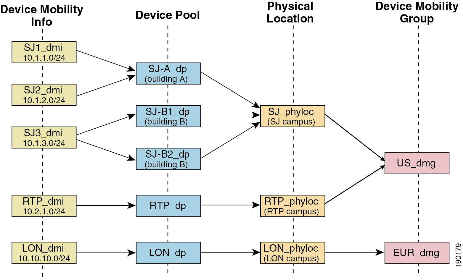
Page 88
Table 5: Device Mobility Scenarios
System Response
Scenario
The system does not consider the phone to be
roaming, and the system uses the settings in the
home location device pool.
The physical location setting in the phone device
pool matches the physical location setting in a
device pool that is associated with the matching
subnet.
Note
Although the phone may have moved from one
subnet to another, the physical location and
associated services have not changed.
The system considers the phone to be roaming. It
reregisters with the parameters of the device pool
for the matching subnet.
The matching subnet has a single device pool that
is assigned to it; the subnet device pool differs from
the home location device pool, and the physical
locations differ.
The system considers the phone to be roaming. The
new device pool gets assigned according to a
round-robin rule. Each time that a roaming device
comes in to be registered for the subnet, the next
device pool in the set of available device pools gets
assigned.
The physical locations differ, and the matching
subnet has multiple device pools assigned to it.
The physical location has not changed, so the phone
remains registered in the home device pool.
Physical location gets defined for the home device
pool but is not defined for the device pools that are
associated with the matching subnet.
The system considers the phone to be roaming to
the defined physical location, and it registers with
the parameters of the device pool for the matching
subnet.
Physical location that is not defined for the home
device pool gets defined for the device pools that
are associated with the matching subnet.
The rules for roaming and assigning device pools
get applied by using the remaining subnets.
A subnet gets updated or removed.
If no device mobility information entries match the device IP address, the device uses the home location device
pool settings.
Note
Device Mobility Groups Operations Summary
You can use device mobility groups to determine when a device moves to another location within a geographic
entity, so a user can use its own dial plan. For example, you can configure a device mobility group for the
United States and another group for the United Kingdom. If a phone moves into a different mobility group
(such as from the United States to the United Kingdom), Unified Communications Manager uses the Calling
Search Space, AAR Group and AAR CSS from the phone record, and not from the roaming location.
Feature Configuration Guide for Cisco Unified Communications Manager, Release 15 and SUs
46
Remote Worker Features
Device Mobility Groups Operations Summary

Page 89
If the device moves to another location with same mobility group (for example, Richardson, USA, to Boulder,
USA), the CSS information gets taken from the roaming device pool settings. With this approach, if the user
is dialing PSTN destinations, the user reaches the local gateway.
The following table describes the device pool parameters that the system uses for various scenarios.
Table 6: Device Mobility Group Scenarios
Parameters Used
Scenario
Roaming Device Pool: yes
Location: Roaming device pool setting
Region: Roaming device pool setting
Media Resources Group List: Roaming device pool setting
Device CSS: Roaming device pool setting (Device Mobility CSS)
AAR Group: Roaming device pool setting
AAR CSS: Roaming device pool setting
A roaming device moves
to another location in the
same device mobility
group.
Roaming Device Pool: yes
Location: Roaming device pool setting
Region: Roaming device pool setting
Media Resources Group List: Roaming device pool setting
Device CSS: Home location settings
AAR Group: Home location settings
AAR CSS: Home location settings
A roaming device moves
to another location in a
different device mobility
group.
Because the device is roaming, it takes the roaming device pool settings, including
the Device Mobility Calling Search Space, AAR Calling Search Space, and AAR
Group.
A device roams, and a
device mobility group
does not get defined for
the home or roaming
device pool.
Device Mobility Prerequisites
• The phone must have a dynamic IP address to use device mobility. If a phone with a static IP address
roams, Unified Communications Manager uses the configuration settings from its home location.
• The Device Mobility feature requires you to set up device pools with site-specific settings. This chapter
describes only the device pool settings that relate to device mobility. For more detailed information on
configuring device pools, see the "Configure Device Pools" chapter in the System Configuration Guide
for Cisco Unified Communications Manager.
• Cisco Database Layer Monitor service must be running on the same node as the Cisco CallManager
service.
• Cisco TFTP service must be running on at least one node in the cluster.
Feature Configuration Guide for Cisco Unified Communications Manager, Release 15 and SUs
47
Remote Worker Features
Device Mobility Prerequisites
Page 90
• Cisco Unified Communications Manager Locale Installer (if you want to use non-English phone locales
or country-specific tones).
• Any phone that runs either SCCP or SIP.
Device Mobility Configuration Task Flow
Complete these tasks to configure device mobility.
Procedure
Purpose
Command or Action
Enables device support through a clusterwide
service parameter, or within the Phone
Configuration window of an individual device.
Enable device mobility at the device level by
completing either of these tasks:
Step 1
• Enable Device Mobility Clusterwide, on
page 48
• Enable Device Mobility for Individual
Devices, on page 49
Set up the physical locations that you will assign
to your device pools.
Configure a Physical Location, on page 49
Step 2
A device mobility group is a logical grouping
of sites with similar dialing patterns.
Configure a Device Mobility Group, on page
50
Step 3
Assign the physical location, device mobility
group, and other device mobility-related
Configure a Device Pool for Device Mobility,
on page 50
Step 4
information to device pools that will be used
for device mobility.
Assign the IP subnets where roaming devices
can register and the device pools that can be
assigned to those roaming devices.
Configure Device Mobility Information, on
page 51
Step 5
Enable Device Mobility Clusterwide
Use the following procedure to configure a service parameter that sets the default device mobility setting to
On for all phones clusterwide except where there is an overriding configuration in that phone's Phone
Configuration.
Procedure
Step 1
From Cisco Unified CM Administration, choose System > Service Parameters.
Step 2
From the Server drop-down list, choose the node that is running the Cisco CallManager service.
Step 3
From the Service drop-down list, choose Cisco CallManager Service.
Step 4
Under Clusterwide Parameters (Device - Phone), set the Device Mobility Mode service parameter to On.
Feature Configuration Guide for Cisco Unified Communications Manager, Release 15 and SUs
48
Remote Worker Features
Device Mobility Configuration Task Flow
Page 91
Step 5
Click Save.
For devices that are already registered, you must restart the Cisco CallManager service for this new setting
to be enabled.
What to do next
If you want to configure device mobility settings for an individual device, go to Enable Device Mobility for
Individual Devices, on page 49.
Otherwise, you can begin configuring the system for device mobility. Go to Configure a Physical Location,
on page 49.
Enable Device Mobility for Individual Devices
Use this procedure to enable device mobility for an individual device. This configuration overrides the setting
of the Device Mobility Mode clusterwide service parameter.
Procedure
Step 1
From Cisco Unified CM Administration, choose Device > Phone.
Step 2
Click Find and select the device that you want to configure.
Step 3
From the Device Mobility Mode drop-down list, choose one of the following:
• On—Device mobility is enabled for this device.
• Off—Device mobility is disabled for this device.
• Default—The device uses the setting of the Device Mobility Mode clusterwide service parameter. This
is the default setting.
Step 4
Click Save.
Configure a Physical Location
Use this procedure to configure a physical location that you will assign to a device pool. Device Mobility uses
the location of the device registration to assign an appropriate device pool.
Procedure
Step 1
From Cisco Unified CM Administration, choose System > Physical Location.
Step 2
Click Add New.
Step 3
Enter a Name for the location.
Step 4
Enter a Description for the location.
Step 5
Click Save.
Feature Configuration Guide for Cisco Unified Communications Manager, Release 15 and SUs
49
Remote Worker Features
Enable Device Mobility for Individual Devices
Page 92
Configure a Device Mobility Group
Use the following procedure to configure device mobility group is a logical grouping of sites with similar
dialing patterns. For example, a company with a worldwide network may want to set up device mobility
groups that represent individual countries.
Procedure
Step 1
From Cisco Unified CM Administration, choose System > Device Mobility > Device Mobility Group.
Step 2
Click Add New.
Step 3
Enter a Name for the device mobility group.
Step 4
Enter a Description for the device mobility group.
Step 5
Click Save.
Configure a Device Pool for Device Mobility
Use this procedure to set up a device pool with parameters that you configured for device mobility.
Procedure
Step 1
From Cisco Unified CM Administration, choose System > Device Pool.
Step 2
Do either of the following:
• Click Find and select an existing device pool.
• Click Add New to create a new device pool.
Step 3
Under Roaming Sensitive Settings, assign the parameters that you set up in the previous device mobility
tasks:
• Physical Location—From the drop-down list, select the physical location that you set up for this device
pool. Device mobility uses this location to assign a device pool for a roaming device.
• Device Mobility Group—From the drop-down list, select the device mobility group that you set up for
this device pool.
Step 4
Under Device Mobility Related Information, configure the following device mobility-related fields. For
more information on the fields and their configuration options, see Online Help.
• Device Mobility Calling Search Space—Select the CSS to be used by a roaming device that uses this
device pool.
• AAR Calling Search Space—Select the calling search space for the device to use when automated
alternate routing (AAR) is performed.
• AAR Group—If AAR is configured, select the AAR Group for this device.
• Calling Party Transformation CSS—Select the calling party transformation CSS for roaming devices
that use this device pool.
Note
Feature Configuration Guide for Cisco Unified Communications Manager, Release 15 and SUs
50
Remote Worker Features
Configure a Device Mobility Group
Page 93
• The Calling Party Transformation CSS overrides the device level configuration for roaming devices,
even if the Use Device Pool Calling Party Transformation CSS check box is unchecked in the Phone
Configuration window.
• The Called Party Transformation CSS setting is applied to the gateway rather than to the roaming
device.
Step 5
Configure any remaining fields in the Device Pool Configuration window. For more information on the
fields and their configuration options, see the system Online Help.
Step 6
Click Save.
Configure Device Mobility Information
Use this procedure to configure Device Mobility Info, representing the IP subnets to which roaming devices
can register and the corresponding device pools that the system can assign to roaming devices.
Procedure
Step 1
From Cisco Unified CM Administration, choose System > Device Mobility > Device Mobility Info.
Step 2
Click Add New.
Step 3
Enter a Name for the Device Mobibility Info.
Step 4
Enter the IP subnet details for roaming device registrations.
• If you are using IPv4 addresses for your mobile devices, complete the IPv4 subnet details.
• If you are using IPv6 addresses for your mobile devices, complete the IPv6 subnet details.
Step 5
Select the device pools that you want the system to assign for roaming devices that register to one of these
subnets. Use the arrows to move the appropriate device pools from the Selected Device Pools list box to the
Available Device Poolss list box.
Step 6
Click Save.
For more information on the fields and their configuration options, see Online Help.
View Roaming Device Pool Parameters
Use the following procedure to view and verify the current device mobility settings for a device.
Procedure
Step 1
From Cisco Unified CM Administration, choose Device > Phone.
Step 2
Enter search criteria and click Find to find the device with device mobility mode enabled.
Step 3
Click View Current Device Mobility Settings next to the Device Mobility Mode field.
Feature Configuration Guide for Cisco Unified Communications Manager, Release 15 and SUs
51
Remote Worker Features
Configure Device Mobility Information
Page 94
The roaming device pool settings appear. If the device is not roaming, the home location settings appear.
Device Mobility Interactions
Table 7: Device Mobility Interactions
Interaction
Feature
Calling party normalization enhances the dialing capabilities of some phones and
improves call-back functionality when a call is routed to multiple geographical
locations; that is, the feature ensures that the called party can return a call without
the need to modify the directory number in the call log directories on the phone.
Additionally, calling party normalization allows you to globalize and localize
phone numbers, so the appropriate calling number presentation is displayed on
the phone.
Calling Party
Normalization
When a device is roaming in the same device mobility group, Unified
Communications Manager uses the device mobility CSS to reach the local
gateway. If a user sets call forward all (CFA) at the phone, the CFA CSS is set
to None, and the CFA CSS activation policy is set to With Activating Device/Line
CSS, then the following behaviors will occur, depending on the device location:
• The Device CSS and Line CSS are used as the CFA CSS when the device
is in its home location.
• If the device is roaming within the same device mobility group, the device
mobility CSS from the roaming device pool and the line CSS are used as
the CFA CSS.
• If the device is roaming within a different device mobility group, the Device
CSS and Line CSS are used as the CFA CSS.
Roaming
Feature Configuration Guide for Cisco Unified Communications Manager, Release 15 and SUs
52
Remote Worker Features
Device Mobility Interactions
Page 95
Device Mobility Restrictions
Table 8: Device Mobility Restrictions
Description
Restriction
The device mobility feature depends on the IPv4 address or IPv6 address of the
device that registers with Unified Communications Manager.
• The phone must have a dynamic IPv4 address or IPv6 address to use the
device mobility.
• If the device is assigned an IP address by using network address translation
(NAT) or port address translation (PAT), the IP address that is provided
during registration may not match the actual IP address of the device.
• If the Cisco IP phone supports IPv4-Only Stack or IPv6-Only Stack, then
the phone gets re-associated either with IPv4 or IPv6 Device Mobility
Information, based on the IP addressing mode preference defined. For
example, when a phone is defined with IPv6 preference but has no matching
Device Mobility Information (IPv6 subnet and mask size), then it is
associated with IPv4. When you add matching IPv6 Device Mobility
Information, then the phone gets re-associated with IPv6 Device Mobility
Information.
IP Address
Feature Configuration Guide for Cisco Unified Communications Manager, Release 15 and SUs
53
Remote Worker Features
Device Mobility Restrictions
Page 96
Feature Configuration Guide for Cisco Unified Communications Manager, Release 15 and SUs
54
Remote Worker Features
Device Mobility Restrictions
Page 97
C H A P T E R 6
Extend and Connect
• Extend and Connect Overview, on page 55
• Extend and Connect Prerequisites, on page 56
• Extend and Connect Configuration Task Flow, on page 56
• CTI Remote Device (CTIRD) Call Flows, on page 61
• Extend and Connect Interactions, on page 62
• Extend and Connect Restrictions, on page 63
Extend and Connect Overview
The Extend and Connect feature allows administrators to deploy Unified Communications Manager (UC)
Computer Telephony Integration (CTI) applications that interoperate with any endpoint. With Extend and
Connect, users can access UC applications from any location using any device.
The Extend and Connect feature for Unified Communications Manager provides the following UC features:
• Receive incoming enterprise calls
• Make Call
• Disconnect
• Hold and Retrieve
• Redirect and Forward
• Call Forward All
• Call Forward Busy
• Call Forward No Answer
• Do Not Disturb
• Play Dual Tone Multi Frequency (DTMF) (out-of-band and in-band)
• Consult Transfer, Conference
• Add, edit, and delete remote destinations
• Set remote destination as Active or Inactive
Feature Configuration Guide for Cisco Unified Communications Manager, Release 15 and SUs
55

Page 98
• Persistent Connection
• Play Whisper Announcement
Extend and Connect Prerequisites
• Cisco Jabber, Release 9.1(1) or later
• Cisco Unified Workspace License (CUWL) Standard, CUWL Professional, or Cisco User Connect
License (UCL) - Enhanced
Extend and Connect Configuration Task Flow
This section describes the procedures that you must complete to provision Unified Communications Manager
users with Extend and Connect capabilities. For information about provisioning Cisco Jabber for Windows
users with Extend and Connect, see the Cisco Jabber for Windows Installation and Configuration Guide.
Before you begin
Procedure
Purpose
Command or Action
Enable mobility for users so that they can use
CTI remote devices. CTI devices are off-cluster
phones that work with Cisco UC applications.
Configure User Account, on page 56
Step 1
Add access control group permissions.
Add User Permissions, on page 57
Step 2
Configure off-cluster phones that users can use
with Cisco UC applications.
Create CTI Remote Devices, on page 58
Step 3
Associate a directory number with the CTI
remote device.
Add Directory Number to a Device, on page
58
Step 4
Add a numerical address or directory URI that
represents the other phones that the user owns.
Add Remote Destination, on page 59
Step 5
Verify if the remote destination is successfully
added for a user.
Verify Remote Destination, on page 60
Step 6
Associate an end user account to the CTI remote
device.
Associate User with Device, on page 60
Step 7
Configure User Account
Use the following procedure to configure a new or existing user in Unified Communications Manager, you
must enable user mobility so that they can use CTI remote devices. If you do not enable mobility for users,
you cannot assign those users as owners of CTI remote devices.
Feature Configuration Guide for Cisco Unified Communications Manager, Release 15 and SUs
56
Remote Worker Features
Extend and Connect Prerequisites
Page 99
Procedure
Step 1
From Cisco Unified CM Administration, choose User Management > End User.
Step 2
Perform either of the following:
• Click Add New, to configure a new user.
• Apply the filters using the Find User Where field and click Find to retrieve a list of users.
Note
You may add the new end user account through LDAP integration or local configuration.
Step 3
Locate the Mobility Information section.
Step 4
Check the Enable Mobility check box.
Step 5
Click Save.
Add User Permissions
After the end user is active in Unified Communications Manager, add access control group permissions.
Procedure
Step 1
From Cisco Unified CM Administration, choose User Management > End User.
Step 2
Specify the appropriate filters in the Find User Where field, and then select Find to retrieve a list of users.
Step 3
Select the user from the list.
Step 4
Locate the Permissions Information section.
Step 5
Click Add to Access Control Group.
The Find and List Access Control Groups window appears.
Step 6
Click Find.
The Access Control Group list for Standard Users appears.
Step 7
Check the check boxes next to the following permissions:
• Standard CCM End-Users
• Standard CTI Enabled
Step 8
Click Add Selected.
Step 9
Click Save.
Feature Configuration Guide for Cisco Unified Communications Manager, Release 15 and SUs
57
Remote Worker Features
Add User Permissions
Page 100
Create CTI Remote Devices
Use the following procedure to create a CTI remote device is a device type that represents off-cluster phones
that users can use with Cisco UC applications. The device type is configured with one or more lines (directory
numbers) and one or more remote destinations.
Unified Communications Manager provides Extend and Connect capabilities to control calls on devices such
as public switched telephone network (PSTN) phones and private branch exchange (PBX) devices.
Procedure
Step 1
From Cisco Unified CM Administration, choose Device > Phone.
Step 2
Click Add New.
Step 3
Select CTI Remote Device from the Phone Type drop-down list and then click Next.
Step 4
Select the appropriate user ID from the Owner User ID drop-down list.
Note
Only users for whom you enable mobility are available from the Owner User ID drop-down list.
Unified Communications Manager populates the Device Name field with the user ID and a CTRID prefix,
for example, CTRIDusername.
Step 5
Edit the default value in the Device Name field, if appropriate.
Step 6
Enter a meaningful description in the Description field.
Note
Cisco Jabber displays device descriptions to users. If Cisco Jabber users have multiple devices of the same
model, the descriptions from Unified Communications Manager help users tell the difference between them.
Step 7
Ensure that you select an appropriate option from the Rerouting Calling Search Space drop-down list in the
Protocol Specific Information section.
The Rerouting Calling Search Space drop-down list defines the calling search space for rerouting and ensures
that users can send and receive calls from the CTI remote device.
Step 8
Configure the remaining fields in the Phone Configuration window. For more information on the fields and
their configuration options, see Online Help.
Step 9
Click Save.
The fields to associate directory numbers and add remote destinations are displayed in the Phone Configuration
window.
Add Directory Number to a Device
A directory number (DN) is a numerical address that is configured as a line on the CTI remote device. A DN
typically represents the primary work number of a user (for example, 2000 or +1 408 200 2000).
Feature Configuration Guide for Cisco Unified Communications Manager, Release 15 and SUs
58
Remote Worker Features
Create CTI Remote Devices
Page 101
• The Calling Search Space (CSS) and partition of DN are mandatory on devices.
• The CTI Remote Device should not block its own DN. The CSS is important for the CTIRD device to
reach its own DN.
Note
Follow these steps to add a directory number to a CTI remote device.
Procedure
Step 1
Locate the Association Information section in the Phone Configuration window.
Step 2
Click Add a new DN.
Step 3
Specify a directory number in the Directory Number field.
Step 4
Configure all other required fields. For more information on the fields and their configuration options, see
Online Help.
Step 5
Click Save.
Add Remote Destination
Use the following procedure to add a remote destination is a numerical address or directory URI that represents
the other phones that the user owns (for example, a home office line or other PBX phone). A remote destination
may be any off-cluster device. Unified Communications Manager automatically applies application dial rules
to all remote destination numbers for CTI remote devices. By default, four remote destinations are supported
per device. You can set the maximum number to 10 remote destinations per device in End User Configuration
window.
You can determine which remote destination the Jabber client has set as Active by opening the Phone
Configuration window from the Cisco Unified Communications Manager Administration interface.
Note
Unified Communications Manager users can add remote destinations through the Cisco Jabber interface. For
more information, see the Cisco Jabber for Windows Installation and Configuration Guide.
• Unified Communications Manager automatically verifies whether it can route calls to remote destinations
that Cisco Jabber users add through the client interface.
• Unified Communications Manager does not verify whether it can route calls to remote destinations that
you add through the Cisco Unified Communications Manager Administration interface.
Note
Feature Configuration Guide for Cisco Unified Communications Manager, Release 15 and SUs
59
Remote Worker Features
Add Remote Destination

Page 102
Procedure
Step 1
From Cisco Unified CM Administration, choose Device > Phone.
Step 2
Specify the appropriate filters in the Find Phone Where field to and then click Find to retrieve a list of
phones.
Step 3
Select the CTI remote device from the list.
Step 4
Locate the Associated Remote Destinations section.
Step 5
Click Add a New Remote Destination.
Step 6
Enter the destination number in the Destination Number field.
To use the remote destination with Cisco Jabber clients, you must configure the destination name as JabberRD.
Step 7
Configure the remaining fields in the Remote Destination Information window. For more information on
the fields and their configuration options, see Online Help.
Step 8
Click Save.
Verify Remote Destination
Perform these steps to verify if the remote destination is successfully added for a user.
Procedure
Step 1
From Cisco Unified CM Administration, choose Device > Phone.
Step 2
Specify the appropriate filters in the Find Phone Where field to and then click Find to retrieve a list of
phones.
Step 3
Select the CTI remote device from the list.
Step 4
Locate the Associated Remote Destinations section and verify that the remote destination is available.
Step 5
Click Apply Config.
Note
The Device Information section on the Phone Configuration window indicates when a remote destination
is active or controlled by Cisco Jabber.
Associate User with Device
Procedure
Step 1
From Cisco Unified CM Administration, choose User Management > End User.
Step 2
Specify the appropriate filters in the Find User Where field to and then click Find to retrieve a list of users.
Feature Configuration Guide for Cisco Unified Communications Manager, Release 15 and SUs
60
Remote Worker Features
Verify Remote Destination
Page 103
Step 3
Select the user from the list.
Step 4
Locate the Device Information section.
Step 5
Click Device Association.
Step 6
Find and select the CTI remote device.
Step 7
To complete the association, click Save Selected/Changes.
Step 8
From Related Links drop-down list, choose Back to User, and then click Go.
The End User Configuration window appears, and the associated device that you chose appears in the
Controlled Devices pane.
CTI Remote Device (CTIRD) Call Flows
Unified Communications Manager supports the separate calling party number and billing number feature
when users are added as CTI Remote Device. Each CTI Remote Device is configured with the user directory
number (DN) (for example, 2000) and a remote destination that represents any off-cluster device (for example,
a PBX phone with the number +1 408 111 1111).
When a call is initiated from the PSTN network to a CTIRD line, Unified Communications Manager looks
for FROM and PAID header information. The FROM header contains the external presentation name and
number and PAID contains the identity of the user (that is a user’s DN or DDI).
If FROM and PAID headers have different numbers and Enable External Presentation Name and Number
check box is checked in its SIP profile and Display External Presentation Name and Number service
parameter value set to True, then Unified Communications Manager displays the FROM header information
on the called device. In the same way, if any one option is disabled,Unified Communications Manager displays
PAID header information on the called device.
Similarly, in the outgoing call scenario a user calls from Remote Destination (CTIRD line) configured with
External Presentation Name and External Presentation Number on Directory Number configuration page
to a PSTN network through a SIP trunk with Enable External Presentation Name and Number configured
in its SIP profile. Then, Unified Communications Manager send the External Presentation Information
configured on the Directory Number Configuration page in the FROM header of the outgoing SIP message
to display on the called device.
If Enable External Presentation Name and Number check box is unchecked, then Unified Communications
Manager sends the directory number information in the FROM and PAID to display on the called device and
configured External Presentation Information in the X-Cisco-Presentation header.
If you check the Anonymous External Presentation check box, the configured External Presentation Name
and Number are removed from the respective fields and external presentation displayed as anonymous on the
called device.
For more details on Configuring External Presentation Information, see the Configure Directory Number
chapter in the System Configuration Guide for Cisco Unified Communications Manager.
Feature Configuration Guide for Cisco Unified Communications Manager, Release 15 and SUs
61
Remote Worker Features
CTI Remote Device (CTIRD) Call Flows
Page 104
Extend and Connect Interactions
Table 9: Extend and Connect Interactions
Interaction
Feature
Configure a Directory URI as the DN, remote destination, or both for the CTI
remote device.
Directory URI Dialing
Extend and Support does not support moving active calls between a Cisco Unified
IP Phone and a remote destination.
If you want the capabilities of both Unified Mobility and Extend and Connect,
you can configure the same remote destination on the Remote Device Profile and
CTI Remote Device types when the Owner ID of both device types is the same.
This configuration allows Cisco Mobility features to be used concurrently with
Extend and Connect. The ability to configure the same remote destination on
both device types is supported using Cisco Unified Communications Manager
Release 10.0(1) or later.
Do not configure remote destinations that are used with the Cisco Extend and
Connect feature on Cisco Dual-mode for iPhone, Cisco Dual-mode for Android,
and Carrier-integrated Mobile device types. Do not use prefixes to differentiate
the same remote destination address. For example, 91-4085555555 and
+1-4085555555 are treated as the same number.
Unified Mobility
The Extend and Connect feature allows users to receive hunt calls on remote
destination phones under the following conditions:
• The user has a Cisco Unified IP Phone.
• The Cisco Unified IP Phone is available to answer hunt calls
(logged-in/HLog).
• Cisco Jabber is running in Extend and Connect mode.
Hunt List
• The incoming caller ID information (name and number) is displayed on the
Jabber client.
• This information may also be displayed on the device, depending on your
carrier and trunk configuration.
• Outbound Dial Via Office calls to the remote destination display Voice
Connect as the name and the trunk DID as the number.
• Configure the trunk DID in the Unified CM Trunk Pattern, Route Pattern,
or Cisco Gateway. This configuration may also be assigned by the carrier.
The number field may display as blank if the trunk DID is not configured.
• Outbound calls to the desired party display the CTI Remote Device Display
Name and Directory Number (DN) as configured in Unified Communications
Manager.
• Remote destination numbers are never displayed to the called party.
CallerID Information
Feature Configuration Guide for Cisco Unified Communications Manager, Release 15 and SUs
62
Remote Worker Features
Extend and Connect Interactions
Page 105
Extend and Connect Restrictions
Table 10: Extend and Connect Restrictions
Description
Restriction
You can configure up to ten remote destinations for each CTI remote device.
Note
By default, four remote destinations are supported per device. You can set the
maximum number to 10 remote destinations per device.
Maximum number of
remote destinations
• Remote destination numbers must represent off-cluster devices.
• Remote destinations can be off-cluster URIs.
Off-cluster devices
You cannot configure directory numbers as remote destination numbers.
Directory numbers
Before you save the remote destinations that are configured using Cisco Jabber,
verify if the remote destinations can be routed by the configured dial plan.
Cisco Jabber
Application Dial Rules are applied to all remote destinations that are configured
on the CTI remote device through the Cisco Unified Communications Manager
Administration interface and Cisco Jabber.
Note
Advise end users which number formats the Application Dial Rules are
configured to support (for example, nn-nnn-nnnn, E.164, both).
Application dial rules
Each remote destination number must be unique within the cluster.
Note
Two or more users cannot use the same remote destination numbers.
Remote destination
number
• Remote destination numbers are validated using the CTI remote device
reroute calling search space.
• Remote destinations that are configured using the Cisco Unified
Communications Manager Administration interface and AXL interface are
not validated.
Remote destination
validation
When a consult transfer is initiated from a CTI Remote Device to an internal IP
phone or another extend and connect enabled device, no ringback is heard on the
remote destination associated to the CTI Remote device which is initiating the
transfer.
Consult transfer limitation
Extend and Connect does not support Call Forward Unregistered Internal or Call
Forward Unregistered External.
Call Forward
Unregistered
Extend and Connect does not support Translation Patterns when the "Route Next
Hop By Calling Party Number" option is enabled.
Route Next Hop By
Calling Party Number
Feature Configuration Guide for Cisco Unified Communications Manager, Release 15 and SUs
63
Remote Worker Features
Extend and Connect Restrictions
Page 106
Feature Configuration Guide for Cisco Unified Communications Manager, Release 15 and SUs
64
Remote Worker Features
Extend and Connect Restrictions
Page 107
C H A P T E R 7
Remote Worker Emergency Calling
• Remote Worker Emergency Calling Overview, on page 65
• Remote Worker Emergency Calling Prerequisites, on page 65
• Remote Worker Emergency Calling Configuration Task Flow, on page 66
Remote Worker Emergency Calling Overview
The Remote Worker Emergency Calling feature enables customers to provide reliable emergency calling
support to remote workers by using remote Virtual Private Network (VPN) connections. Emergency calls
from off-premises users are routed to the Public Safety Answering Point (PSAP), and user-provided location
information is delivered with each call.
To use this feature, remote workers must confirm or update their location whenever their device registration
is interrupted. A customizable disclaimer notice is first displayed on the devices that are designated for
off-premises (connected remotely to the customer network), which advises the users to provide correct location
information. After the location information is provided, the off-premises location that is currently associated
with the designated device is displayed. Users can confirm their current location or select another previously
stored location from their device display; if their location is new, they are directed to the Cisco Emergency
Responder Off-Premises User web page to create a new location.
Before completing this process, the administrator may restrict the device to calling a single configured
destination. This action ensures that the device user has acknowledged the disclaimer and provided current
location information before the device is enabled for normal use.
Remote Worker Emergency Calling Prerequisites
You must configure Intrado (a third party application) on the Cisco Emergency Responder before you configure
the Remote Worker Emergency Calling feature. For information about configuring Intrado on the Cisco
Emergency Responder, see Cisco Emergency Responder Administration Guide
Feature Configuration Guide for Cisco Unified Communications Manager, Release 15 and SUs
65

Page 108
Remote Worker Emergency Calling Configuration Task Flow
Before you begin
Procedure
Purpose
Command or Action
Associate the off-premises device with the
owner of the device.
Configure User As a Remote Worker, on page
66
Step 1
These parameters specify the calling search
space and destination number that are used to
Specify Alternate Routing for Emergency
Calling, on page 67
Step 2
restrict the routing of any call that is made from
a registered off-premises device where the user
chose not to set a location. If these parameters
are not configured, calls are routed normally.
Direct end users to the application server where
they enter the location of the device.
Configure the Application Server, on page 67
Step 3
Configure the E911 messages that appear on an
off-premises end-user phone.
Configure E911 Messages, on page 67
Step 4
Configure User As a Remote Worker
Before you begin
Ensure that you have configured Intrado on the Cisco Emergency Responder. For more information about
configuring Intrado on the Cisco Emergency Responder, see Cisco Emergency Responder Administration
Guide.
Procedure
Step 1
From Cisco Unified CM Administration, choose Device > Phone.
Step 2
Enter the appropriate search criteria to find the phone and click Find.
A list of phones that match the search criteria is displayed.
Step 3
Choose the phone for which you want to configure Remote Worker Emergency Calling.
The Phone Configuration window is displayed.
Step 4
From the Device Information section, select the appropriate user ID from the Owner User ID drop-down
list and check the Require off-premise location check box.
Step 5
Click Save.
Feature Configuration Guide for Cisco Unified Communications Manager, Release 15 and SUs
66
Remote Worker Features
Remote Worker Emergency Calling Configuration Task Flow
Page 109
Specify Alternate Routing for Emergency Calling
Perform the following steps to configure calling search space and destination number. These parameters are
used to restrict the routing of any call made from a registered off-premises device where the user has not set
a location. If you do not configure these parameters, the calls are routed normally.
Procedure
Step 1
From Cisco Unified CM Administration, choose System > Service Parameters.
Step 2
From the Server drop-down list, choose a server.
Step 3
From the Service drop-down list, choose Cisco CallManager.
The Service Parameter Configuration window appeares.
Step 4
In the Clusterwide Parameters (Emergency Calling for Required Off-premise Location) section, specify
Alternate Destination for Emergency Call.
Step 5
Specify Alternate Calling Search Space for Emergency Call.
Step 6
Click Save.
Configure the Application Server
You must configure the application server to enable the E911 Proxy to communicate with the Cisco Emergency
Responder. E911 proxy is used to direct the users to the application server where they enter the location of
the device.
Procedure
Step 1
From Cisco Unified CM Administration, choose System > Application Server.
Step 2
Click Add New.
The Application Server window appears.
Step 3
From the Application Server Type drop-down list, select CER Location Management.
Step 4
Click Next.
Step 5
In the Name field, specify a name to identify the application server that you are configuring.
Step 6
In the IP address field, specify the IP address of the server that you are configuring.
Step 7
From the list of Available Application Users, select the application user and click the Down arrow.
Step 8
In the End User URL field, enter a URL for the end users that are associated with this application server.
Step 9
Click Save.
Configure E911 Messages
Use the following procedure to select and edit E911 messages for off-premises devices.
Feature Configuration Guide for Cisco Unified Communications Manager, Release 15 and SUs
67
Remote Worker Features
Specify Alternate Routing for Emergency Calling
Page 110
Procedure
Step 1
From Cisco Unified CM Administration, choose System > E911 Messages.
Step 2
Select the required language link of the E911 messages.
The E911 Messages Configuration page displays the Agreement, Disclaimer, and Error messages.
Step 3
(Optional) Edit the E911 messages to be displayed on off-premises devices.
Step 4
Click Save.
Feature Configuration Guide for Cisco Unified Communications Manager, Release 15 and SUs
68
Remote Worker Features
Configure E911 Messages
Page 111
C H A P T E R 8
Configure Mobile and Remote Access
• Mobile and Remote Access Overview, on page 69
• Mobile and Remote Access Prerequisites, on page 71
• Mobile and Remote Access Configuration Task Flow, on page 72
• MRA Failover with Lightweight Keepalives, on page 78
Mobile and Remote Access Overview
Unified Communications Manager Mobile and Remote Access is a core part of the Cisco Collaboration Edge
Architecture. It allows endpoints such as Cisco Jabber to have their registration, call control, provisioning,
messaging, and presence services that are provided by Unified Communications Manager when the endpoint
is not within the enterprise network. Cisco Expressway connects the mobile endpoint to the on-premises
network, providing secure firewall traversal and line-side support for Unified CM registrations.
The overall solution provides:
• Off-premises access: a consistent experience outside the network for Jabber and EX/MX/SX Series
clients
• Security: secure business-to-business communications
• Cloud services: enterprise grade flexibility and scalable solutions providing rich Webex integration and
Service Provider offerings
• Gateway and interoperability services: media and signaling normalization, and support for non-standard
endpoints
Feature Configuration Guide for Cisco Unified Communications Manager, Release 15 and SUs
69

Page 112
Figure 2: Unified Communications: Mobile and Remote Access
Third-party SIP or H.323 devices can register to the Expressway-C and, if necessary, interoperate with Unified
CM-registered devices over a SIP trunk.
Figure 3: Typical Call Flow: Signaling and Media Paths
• Unified CM provides call control for both mobile and on-premises endpoints.
• Signaling traverses the Expressway solution between the mobile endpoint and Unified CM.
• Media traverses the Expressway solution and is relayed between endpoints directly; all media is encrypted
between the Expressway-C and the mobile endpoint.
Configuring Mobile and Remote Access
To enable Cisco Jabber users with Mobile and Remote Access functionality, set up an Mobile and Remote
Access User Policy within the User Profile Configuration window of Unified Communications Manager.
The Mobile and Remote Access User Policy is not required for non-Jabber endpoints.
In addition, you must configure Cisco Expressway with Mobile and Remote Access. For details, see Mobile
and Remote Access via Cisco Expressway Deployment Guide .
Feature Configuration Guide for Cisco Unified Communications Manager, Release 15 and SUs
70
Remote Worker Features
Mobile and Remote Access Overview
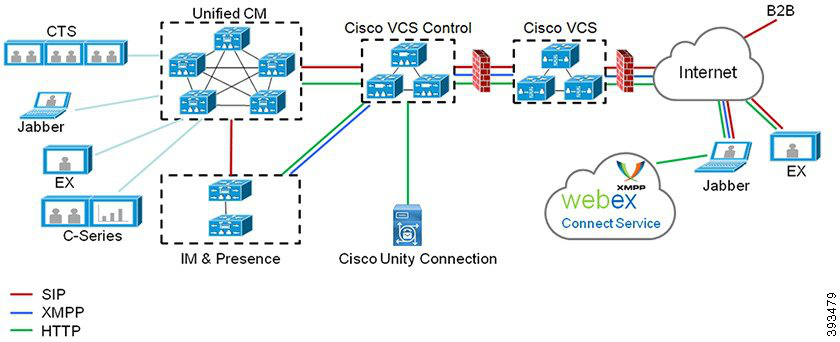
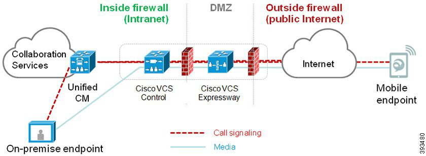
Page 113
Mobile and Remote Access Prerequisites
Cisco Unified Communications Manager Requirements
The following requirements apply:
• If you are deploying multiple Unified Communications Manager clusters, set up an ILS network.
• Mobile and Remote Access requires that you set up NTP servers for your deployment. Make sure that
you have NTP servers deployed for your network and Phone NTP References for SIPendpoints.
• If you are deploying ICE for media path optimization, you will need to deploy a server that can provide
TURN and STUN services.
DNS Requirements
For the internal connection to Cisco Expressway, configure the following locally resolvable DNS SRV that
points to Unified Communications Manager:
_cisco-uds._tcp<domain>
You must create internal DNS records, for both forward and reverse lookups, for all Unified Communications
nodes used with Mobile and Remote Access. This allows Expressway-C to find the nodes when IP addresses
or hostnames are used instead of FQDNs. Make sure that the SRV record is not resolvable outside of the local
network.
Cisco Expressway Requirements
This feature requires you to integrate Unified Communications Manager with Cisco Expressway. For Cisco
Expressway configuration details for Mobile and Remote Access, refer to the Mobile and Remote Access
Through Cisco Expressway Deployment Guide.
The minimum Expressway release for Mobile and Remote Access Access Policy support with Cisco Jabber
is X8.10.
Certificate Prerequisites
You must exchange certificates between Unified Communications Manager, the IM and Presence Service,
and Cisco Expressway-C. Cisco recommends that you use CA-signed certificates with the same CA for each
system. In this case:
• Install the CA root certificate chain on each system (for Unified Communications Manager and the IM
and Presence Service Service install the certificate chain to the tomcat-trust store).
• For Unified Communications Manager, issue a CSR to request CA-signed tomcat (for AXL and UDS
traffic) and Cisco CallManager (for SIP) certificates.
• For the IM and Presence Service Service, issue a CSR to request CA-signed tomcat certificates.
If you use different CAs, you must install each CA's root certificate chain on Unified Communications Manager,
IM and Presence Service Service, and Expressway-C.
Note
Feature Configuration Guide for Cisco Unified Communications Manager, Release 15 and SUs
71
Remote Worker Features
Mobile and Remote Access Prerequisites

Page 114
You can also use self-signed certificates for both Unified Communications Manager and the IM and Presence
Service Service. In this case, you must upload onto Expressway-C the tomcat and Cisco CallManager certificates
for Unified Communications Manager and a tomcat certificate for the IM and Presence Service Service.
Note
Mobile and Remote Access Configuration Task Flow
Complete these tasks in Unified Communications Manager if you want to deploy Mobile and Remote Access
endpoints.
Procedure
Purpose
Command or Action
Make sure that the Cisco AXL Web Service is
activated on the publisher node.
Activate Cisco AXL Web Service, on page 73
Step 1
Optional. Configure Region-specific settings
for your Mobile and Remote Access endpoints.
Configure Maximum Session BitRate for Video,
on page 73
Step 2
For example, if you expect Mobile and Remote
Access endpoints to use video, you may want
to increase the Maximum Session Bit Rate for
Video Calls setting as the default setting of 384
kbps may be too low for some video endpoints.
Assign your Date/Time Group and Region
configuration to the device pool that your
Mobile and Remote Access endpoints use.
Configure a Device Pool for Mobile and
Remote Access, on page 74
Step 3
Optional. ICE is an optional deployment that
uses STUN and TURN services to analyze the
Configure ICE, on page 74
Step 4
available media paths for an Mobile and Remote
Access call and then to select the best path. ICE
adds potentially to the call setup time, but
increases the reliability of Mobile and Remote
Access calls.
Use this procedure to set up a phone security
profile to be used by Mobile and Remote Access
endpoints.
Configure Phone Security Profile for Mobile
and Remote Access, on page 75
Step 5
Cisco Jabber only. Set up an Mobile and
Remote Access Access Policy for Cisco Jabber
Configure Mobile and Remote Access Access
Policy for Cisco Jabber Users, on page 76
Step 6
users. Cisco Jabber users must be enabled with
Mobile and Remote Access access within their
user profiles in order to use the Mobile and
Remote Access feature.
Feature Configuration Guide for Cisco Unified Communications Manager, Release 15 and SUs
72
Remote Worker Features
Mobile and Remote Access Configuration Task Flow

Page 115
Purpose
Command or Action
For Cisco Jabber users, the User Policy that you
set up must be applied to their End User
Configurations.
Configure Users for Mobile and Remote
Access, on page 77
Step 7
Configure and provision endpoints that use the
Mobile and Remote Access feature.
Configure Endpoints for Mobile and Remote
Access, on page 77
Step 8
Configure Cisco Expressway for Mobile and
Remote Access.
Configure Cisco Expressway for Mobile and
Remote Access, on page 78
Step 9
Activate Cisco AXL Web Service
Make sure that the Cisco AXL Web Service is activated on the publisher node.
Procedure
Step 1
From Cisco Unified Serviceability, choose Tools > Service Activation.
Step 2
From the Server drop-down list, select the publisher node and click Go.
Step 3
Under Database and Admin Services, confirm that the Cisco AXL Web Service is Activated.
Step 4
If the service is not activated, check the corresponding check box and click Save to activate the service.
Configure Maximum Session BitRate for Video
Configure Region settings for your Mobile and Remote Access endpoints. The default settings may be sufficient
in many cases, but if you expect Mobile and Remote Access endpoints to use video, you may want to increase
the Maximum Session Bit Rate for Video Calls within your Region Configuration. The default setting of
384 kbps may be too low for some video endpoints, such as the DX series.
Procedure
Step 1
From Cisco Unified CM Administration, choose System > Region Information > Region.
Step 2
Perform any one of the following:
• Click Find and select the region to edit the bit rates within an existing region.
• Click Add New to create a new region.
Step 3
In the Modify Relationship to other Regions area, configure a new setting for the Maximum Session Bit
Rate for Video Calls. For example, 6000 kbps.
Step 4
Configure any other fields in the Region Configuration window. For more information on the fields and
their configuration options, see Online Help..
Feature Configuration Guide for Cisco Unified Communications Manager, Release 15 and SUs
73
Remote Worker Features
Activate Cisco AXL Web Service
Page 116
Step 5
Click Save.
Configure a Device Pool for Mobile and Remote Access
When you created a new region, assign your region to the device pool that your Mobile and Remote Access
endpoints use.
Procedure
Step 1
From Cisco Unified CM Administration, choose System > Device Pool.
Step 2
Do either of the following:
• Click Find and select the existing device pool to edit.
• Click Add New to create a new device pool.
Step 3
Enter a Device Pool Name.
Step 4
Select a redundant Cisco Unified Communications Manager Group.
Step 5
Assign the Date/Time Group that you set up. This group includes the Phone NTP references that you set up
for Mobile and Remote Access endpoints.
Step 6
From the Region drop-down list, select the region that you configured for Mobile and Remote Access.
Step 7
Complete the remaining fields in the Device Pool Configuration window. For more information on the fields
and their configuration options, see Online Help.
Step 8
Click Save.
Configure ICE
Use this procedure if you want to deploy ICE to handle call setup for Mobile and Remote Access calls. ICE
is an optional deployment that uses STUN and TURN services to analyze the available media paths for an
Mobile and Remote Access call and to select the best path. ICE adds potentially to the call setup time, but
increases the reliability of Mobile and Remote Access calls.
Before you begin
Decide how you are going to deploy ICE. You can configure ICE for groups of phones via the Common Phone
Profile Configuration, to individual Cisco Jabber desktop devices, or through system-wide defaults that apply
to all phones.
As a fallback mechanism, ICE can use a TURN server to relay media. Make sure that you have deployed a
TURN server.
Procedure
Step 1
From Cisco Unified CM Administration:
Feature Configuration Guide for Cisco Unified Communications Manager, Release 15 and SUs
74
Remote Worker Features
Configure a Device Pool for Mobile and Remote Access
Page 117
• Choose System > Enterprise Phone to configure system defaults for ICE.
• Choose Device > Device Settings > Common Phone Profile to configure ICE for groups of endpoints
and select the profile you want to edit.
• Choose Device > Phone to configure ICE for an individual Cisco Jabber desktop endpoint and select
the endpoint that you want to edit.
Step 2
Scroll down to the Interactive Connectivity Establishment (ICE) section.
Step 3
Set the ICE drop-down list to Enabled.
Step 4
Set the Default Candidate Type:
• Host—A candidate obtained by selecting the IP address on the host device. This is the default.
• Server Reflexive—An IP address and port candidate obtained by sending a STUN request. In many
cases, this may represent the public IP address of the NAT.
• Relayed—An IP address and port candidate obtained from a TURN server. The IP address and port are
resident on the TURN server such that media is relayed through the TURN server.
Step 5
From the Server Reflexive Address drop-down list, select whether you want to enable STUN-like services
by setting this field to Enabled or Disabled. You must set this field to enabled if you configured Server
Relexive as the Default Candidate.
Step 6
Enter the IP address or hostname for the Primary and Secondary TURN Servers.
Step 7
Set the TURN Server Transport Type to Auto (default setting), UDP, TCP, or TLS.
Step 8
Enter the Username and Password of the TURN Server.
Step 9
Click Save.
Note
If you configured ICE for a Common Phone Profile, you must associate phones to that Common Phone Profile
for phones to be able to use the profile. You can apply the profile to a phone through the Phone Configuration
window.
Configure Phone Security Profile for Mobile and Remote Access
Use this procedure to set up a phone security profile to be used by Mobile and Remote Access endpoints.
Procedure
Step 1
From Cisco Unified CM Administration, choose System > Security > Phone Security Profile.
Step 2
Click Add New.
Step 3
From the Phone Security Profile Type drop-down list, select your device type. For example, you could select
Cisco Unified Client Service Framework for a Jabber application.
Step 4
Click Next.
Step 5
Enter a Name for the profile. For Mobile and Remote Access, the name must be in FQDN format and must
include the enterprise domain.
Step 6
From the Device Security Mode drop-down list, select Encrypted.
Note
This field must be set to Encrypted. Otherwise, Expressway rejects communications.
Feature Configuration Guide for Cisco Unified Communications Manager, Release 15 and SUs
75
Remote Worker Features
Configure Phone Security Profile for Mobile and Remote Access
Page 118
Step 7
Set the Transport Type to TLS.
Step 8
Leave the TFTP Encrypted Config check box unchecked for the following phones as Mobile and Remote
Access will not work for these phones with this option enabled: DX Series, IP Phone 7800, or IP Phone 8811,
8841, 8845, 8861 and 8865
Step 9
Complete the remaining fields in the Phone Security Profile Configuration window. For more information
on the fields and their configuration options, see Online Help.
Step 10
Click Save.
Note
You must apply this profile to the Phone Configuration for each of your Mobile and Remote Access endpoints.
Configure Mobile and Remote Access Access Policy for Cisco Jabber Users
Use this procedure to set up an Mobile and Remote Access Access Policy for Cisco Jabber users. Cisco Jabber
users must be enabled with Mobile and Remote Access access within their user profiles in order to use the
Mobile and Remote Access feature. The minimum Expressway release for Mobile and Remote Access Policy
support with Cisco Jabber is X8.10.
The Mobile and Remote Access Policy is not required for non-Jabber users.
For more information on user profiles, see "User Profile Overview" section in System Configuration Guide
for Cisco Unified Communications Manager.
Note
Procedure
Step 1
From Cisco Unified CM Administration, choose User Management > User Settings > User Profile.
Step 2
Click Add New.
Step 3
Enter a Name and Description for the user profile.
Step 4
Assign a Universal Device Template to apply to users' Desk Phones, Mobile and Desktop Devices, and
Remote Destination/Device Profiles.
Step 5
Assign a Universal Line Template to apply to the phone lines for users in this user profile.
Step 6
If you want the users in this user profile to be able to use the self-provisioning feature to provision their own
phones, do the following:
a)
Check the Allow End User to Provision their own phones check box.
b) In the Limit Provisioning once End User has this many phones field, enter a maximum number of
phones the user is allowed to provision. The maximum is 20.
c)
Check the Allow Provisioning of a phone already assigned to a different End User check box to
determine whether the user who is associated with this profile has the permission to migrate or reassign
a device that is already owned by another user. By default, this check box is unchecked.
Step 7
If you want Cisco Jabber users who are associated with this user profile, to be able to use the Mobile and
Remote Access feature, check the Enable Mobile and Remote Access check box.
Feature Configuration Guide for Cisco Unified Communications Manager, Release 15 and SUs
76
Remote Worker Features
Configure Mobile and Remote Access Access Policy for Cisco Jabber Users

Page 119
Note
• By default, this check box is selected. When you uncheck this check box, the Client Policies section is
disabled, and No Service client policy option is selected by default.
• This setting is mandatory only for Cisco Jabber users whom are using OAuth Refresh Logins. Non-Jabber
users do not need this setting to be able to use Mobile and Remote Access. Mobile and Remote Access
feature is applicable only for the Jabber Mobile and Remote Access users and not to any other endpoints
or clients.
Step 8
Assign the Jabber policies for this user profile. From the Desktop Client Policy, and Mobile Client Policy
drop-down list, choose one of the following options:
• No Service—This policy disables access to all Cisco Jabber services.
• IM & Presence only—This policy enables only instant messaging and presence capabilities.
• IM & Presence, Voice and Video calls—This policy enables instant messaging, presence, voicemail, and
conferencing capabilities for all users with audio or video devices. This is the default option.
Note
Jabber desktop client includes Cisco Jabber for Windows users and Cisco Jabber for Mac users. Jabber mobile
client includes Cisco Jabber for iPad and iPhone users and Cisco Jabber for Android users.
Step 9
If you want the users in this user profile to set the maximum login time for Extension Mobility or Extension
Mobility Cross Cluster through Cisco Unified Communications Self Care Portal, check the Allow End User
to set their Extension Mobility maximum login time check box.
Note
By default Allow End User to set their Extension Mobility maximum login time check box is unchecked.
Step 10
Click Save.
Configure Users for Mobile and Remote Access
For Cisco Jabber users, the Mobile and Remote Access access policy that you configured must be associated
to your Cisco Jabber users during the LDAP sync. For more information on how to provision end users, see
"End User Configuration" section in System Configuration Guide for Cisco Unified Communications Manager.
Configure Endpoints for Mobile and Remote Access
Provision and configure endpoints for Mobile and Remote Access:
• For Cisco Jabber clients, refer to "Cisco Jabber Configuration Task Flow" section in System Configuration
Guide for Cisco Unified Communications Manager.
• For other endpoints, refer to "Endpoint Device Configuration" section in System Configuration Guide
for Cisco Unified Communications Manager.
Feature Configuration Guide for Cisco Unified Communications Manager, Release 15 and SUs
77
Remote Worker Features
Configure Users for Mobile and Remote Access
Page 120
Configure Cisco Expressway for Mobile and Remote Access
For details on how to configure Cisco Expressway for Mobile and Remote Access, refer to the Mobile and
Remote Access Through Cisco Expressway Deployment Guide.
MRA Failover with Lightweight Keepalives
This section is applicable from Release 14 onwards.
Important
The MRA High-Availability for endpoint registration allows Cisco Webex and Cisco Jabber to detect any
failure of network elements like Cisco Expressway-E, Cisco Expressway-C, and Cisco Unified Communications
Manager Administration in the Registration path and take corrective action to reregister to the Unified CM
through the next available path.
The endpoints send a lightweight STUN keepalive message to check connectivity in the registration path.
When the Unified Communications Manager receives the lightweight STUN keepalive message, it validates
the Cisco Expressway-C IP and responds to the message. The Unified CM discards the STUN keepalive
message if it is received from any other IP.
If a node in the registration path fails, endpoints will learn the failure through the lightweight STUN keepalive
response that they receive and selects a different route path for future messages. This service helps the user
to have smooth and continuous incoming and outgoing calls irrespective of outages or other maintenance
modes.
When Cisco Webex or Cisco Jabber registers to the Unified Communications Manager as a MRA device, the
system displays the Expressway-C’s IP in the Unified CM (Device > Phone > IPv4 Address column).
The Cisco IP Phones do not support registration failover.
Note
For more information, see Mobile and Remote Access Through Cisco Expressway Deployment Guide.
Feature Configuration Guide for Cisco Unified Communications Manager, Release 15 and SUs
78
Remote Worker Features
Configure Cisco Expressway for Mobile and Remote Access


Page 121
P A R T III
Remote Network Access
• Wireless LAN, on page 81
• VPN Client , on page 85

Page 122
Page 123
C H A P T E R 9
Wireless LAN
• Wireless LAN Overview, on page 81
• Wireless LAN Configuration Task Flow, on page 81
Wireless LAN Overview
This feature removes the need for users to configure WiFi parameters on their phones. You can configure
WiFi profiles for them. Devices can then automatically download and apply the WiFi configuration from your
system. You can configure a network access profile, which contains further security layers that are related to
VPN connectivity and HTTP proxy settings.
Wireless LAN Configuration Task Flow
Procedure
Purpose
Command or Action
Generate a report to identify devices that
wireless LAN profiles.
Generate a Phone Feature List, on page 5
Step 1
Optional: Configure a network access profile
if you want to configure VPN and HTTP proxy
Configure a Network Access Profile, on page
82
Step 2
settings that you can link to a wireless LAN
profile.
Configure a wireless LAN profile with common
WiFi settings to apply to devices or device pools
in the enterprise.
Configure a Wireless LAN Profile, on page 82
Step 3
Group wireless LAN profiles together.
Configure a Wireless LAN Profile Group, on
page 82
Step 4
After you complete the device link, TFTP adds
the wireless LAN profile group to the existing
To Link a Wireless LAN Profile Group to a
Device or Device Pool, on page 83, perform
one of the following subtasks:
Step 5
device configuration file, which the device (or
Feature Configuration Guide for Cisco Unified Communications Manager, Release 15 and SUs
81

Page 124
Purpose
Command or Action
devices that are tied to a device pool) proceeds
to download.
• Link a Wireless LAN Profile Group to a
Device, on page 83
• Link a Wireless LAN Profile Group to a
Device Pool, on page 83
Configure a Network Access Profile
Configure a network access profile if you want to configure VPN and HTTP proxy settings that you can link
to a wireless LAN profile.
Procedure
Step 1
From Cisco Unified CM Administration, choose Device > Device Settings > Network Access Profile
Step 2
Click Add New.
Step 3
Configure the fields in the Network Access Profile Configuration window. For more information on the
fields and their configuration options, see Online Help.
Step 4
Click Save.
Configure a Wireless LAN Profile
Configure a wireless LAN profile with common WiFi settings to apply to devices or device pools in enterprise.
Procedure
Step 1
From Cisco Unified CM Administration, choose Device > Device Settings > Wireless LAN Profile
Step 2
Click Add New.
Step 3
Configure the fields in the Wireless LAN Profile Configuration window. For more information on the fields
and their configuration options, see Online Help.
Step 4
Click Save.
Configure a Wireless LAN Profile Group
Group your wireless LAN profiles.
Procedure
Step 1
From Cisco Unified CM Administration, choose Device > Device Settings > Wireless LAN Profile Group.
Feature Configuration Guide for Cisco Unified Communications Manager, Release 15 and SUs
82
Remote Network Access
Configure a Network Access Profile
Page 125
Step 2
Click Add New.
Step 3
Configure the fields in the Wireless LAN Profile Group Configuration window. For more information on
the fields and their configuration options, see Online Help.
Step 4
Click Save.
Link a Wireless LAN Profile Group to a Device or Device Pool
After you complete the device link, TFTP adds the wireless LAN profile group to the existing device
configuration file, which the device (or devices tied to a device pool) proceeds to download.
Procedure
Purpose
Command or Action
Link a Wireless LAN Profile Group to a Device,
on page 83
Step 1
Link a Wireless LAN Profile Group to a Device
Pool, on page 83
Step 2
Link a Wireless LAN Profile Group to a Device
Procedure
Step 1
From Cisco Unified CM Administration, choose Device > Phone.
Step 2
Perform one of the following tasks:
• Click Find to enter search criteria and choose an existing device from the resulting list.
• Click Add New, and choose the device type from the Phone Type drop-down list.
Step 3
From the Wireless LAN Profile Group drop-down list, choose a wireless LAN profile group that you created.
Step 4
Click Save.
Link a Wireless LAN Profile Group to a Device Pool
If you link a wireless LAN profile group at the device and device pool level, your system uses the device pool
setting.
Procedure
Step 1
From Cisco Unified CM Administration, choose System > Device Pool.
Step 2
Perform one of the following tasks:
• Click Find to enter search criteria and choose an existing device pool from the resulting list.
Feature Configuration Guide for Cisco Unified Communications Manager, Release 15 and SUs
83
Remote Network Access
Link a Wireless LAN Profile Group to a Device or Device Pool
Page 126
• Click Add New.
Step 3
From the Wireless LAN Profile Group drop-down list, choose a wireless LAN profile group that you created.
Step 4
Click Save.
Feature Configuration Guide for Cisco Unified Communications Manager, Release 15 and SUs
84
Remote Network Access
Link a Wireless LAN Profile Group to a Device Pool
Page 127
C H A P T E R 10
VPN Client
• VPN Client Overview, on page 85
• VPN Client Prerequisites, on page 85
• VPN Client Configuration Task Flow, on page 85
VPN Client Overview
The Cisco VPN Client for Cisco Unified IP Phone creates a secure VPN connection for employees who
telecommute. All settings of the Cisco VPN Client are configured through Cisco Unified Communications
Manager Administration. After the phone is configured within the Enterprise, the users can plug it into their
broadband router for instant connectivity.
The VPN menu and its options are not available in the U.S. export unrestricted version of Unified
Communications Manager.
Note
VPN Client Prerequisites
Pre-provision the phone and establish the initial connection inside the corporate network to retrieve the phone
configuration. You can make subsequent connections using VPN, as the configuration is already retrieved on
the phone.
VPN Client Configuration Task Flow
Pre-provision the phone and establish the initial connection inside the corporate network to retrieve the phone
configuration. You can make subsequent connections using VPN, as the configuration is already retrieved on
the phone.
Feature Configuration Guide for Cisco Unified Communications Manager, Release 15 and SUs
85


Page 128
Procedure
Purpose
Command or Action
Complete Cisco IOS prerequisites. Perform
this action if you want to configure Cisco IOS
VPN.
Complete Cisco IOS Prerequisites, on page
87
Step 1
Configure Cisco IOS for VPN client on an IP
Phone. Perform this action if you want to
configure Cisco IOS VPN.
Configure Cisco IOS SSL VPN to Support IP
Phones , on page 87
Step 2
Complete ASA prerequisites for AnyConnect.
Perform this action if you want to configure
ASA VPN.
Complete ASA Prerequisites for AnyConnect,
on page 89
Step 3
Configure ASA for VPN client on an IP Phone.
Perform this action if you want to configure
ASA VPN.
Configure ASA for VPN Client on IP Phone,
on page 89
Step 4
To avoid long delays when the user upgrades
the firmware or configuration information on
Configure the VPN concentrators for each
VPN Gateway.
Step 5
a remote phone, set up the VPN concentrator
close in the network to the TFTP or Unified
Communications Manager server. If this is not
feasible in your network, you can set up an
alternate TFTP or load server that is next to
the VPN concentrator.
Upload the VPN concentrator certificates.
Upload VPN Concentrator Certificates, on
page 92
Step 6
Configure the VPN gateways.
Configure VPN Gateway, on page 92
Step 7
After you create a VPN group, you can add
one of the VPN gateways that you just
configured to it.
Configure VPN Group, on page 93
Step 8
You must configure a VPN profile only if you
have multiple VPN groups. The VPN Profile
Perform one of the following:
Step 9
• Configure VPN Profile, on page 94
fields take precedence over the VPN Feature
Configuration fields.
• Configure VPN Feature Parameters, on
page 96
Add the VPN Group and VPN Profile to a
Common Phone Profile.
Add VPN Details to Common Phone Profile,
on page 97
Step 10
To run the Cisco VPN client, a supported Cisco
Unified IP Phone must be running firmware
Upgrade the firmware for Cisco Unified IP
Phone to a version that supports VPN.
Step 11
release 9.0(2) or higher. For more information
about upgrading the firmware, see Cisco
Unified IP Phone Administration Guide for
Unified Communications Manager for
yourCisco Unified IP Phone model.
Feature Configuration Guide for Cisco Unified Communications Manager, Release 15 and SUs
86
Remote Network Access
VPN Client Configuration Task Flow
Page 129
Purpose
Command or Action
Connect your Cisco Unified IP Phone to a
VPN.
Using a supported Cisco Unified IP Phone,
establish the VPN connection.
Step 12
Complete Cisco IOS Prerequisites
Use this procedure to complete Cisco IOS Prerequisites.
Procedure
Step 1
Install Cisco IOS Software version 15.1(2)T or later.
Feature Set/License: Universal (Data & Security & UC) for IOS ISR-G2 and ISR-G3
Feature Set/License: Advanced Security for IOS ISR
Step 2
Activate the SSL VPN License.
Configure Cisco IOS SSL VPN to Support IP Phones
Use this procedure to complete Cisco IOS SSL VPN to Support IP Phones.
Procedure
Step 1
Configure Cisco IOS locally.
a)
Configure the Network Interface.
Example:
router(config)# interface GigabitEthernet0/0
router(config-if)# description "outside interface"
router(config-if)# ip address 10.1.1.1 255.255.255.0
router(config-if)# duplex auto
router(config-if)# speed auto
router(config-if)# no shutdown
router#show ip interface brief (shows interfaces summary)
b) Configure static and default routes by using this command:
router(config)# ip route <dest_ip> < mask> < gateway_ip>
Example:
router(config)# ip route 10.10.10.0 255.255.255.0 192.168.1.1
Step 2
Generate and register the CAPF certificate to authenticate the IP phones with an LSC.
Step 3
Import the CAPF certificate from Unified Communications Manager.
a)
From the Cisco Unified OS Administration, choose Security > Certificate Management.
Note
Feature Configuration Guide for Cisco Unified Communications Manager, Release 15 and SUs
87
Remote Network Access
Complete Cisco IOS Prerequisites
Page 130
This location changes based on the Unified Communications Manager version.
b) Find the Cisco_Manufacturing_CA and CAPF certificates. Download the.pem file and save as.txt file.
c)
Create trustpoint on the Cisco IOS software.
hostname(config)# crypto pki trustpoint trustpoint_name
hostname(config-ca-trustpoint)# enrollment terminal
hostname(config)# crypto pki authenticate trustpoint
When prompted for the base 64-encoded CA certificate, copy and paste the text in the downloaded .pem
file along with the BEGIN and END lines. Repeat the procedure for the other certificates.
d) Generate the following Cisco IOS self-signed certificates and register them with Unified Communications
Manager, or replace with a certificate that you import from a CA.
• Generate a self-signed certificate.
Router> enable
Router# configure terminal
Router(config)# crypto key generate rsa general-keys label <name>
<exportable -optional>Router(config)# crypto pki trustpoint <name>
Router(ca-trustpoint)# enrollment selfsigned
Router(ca-trustpoint)# rsakeypair <name> 2048 2048
Router(ca-trustpoint)#authorization username subjectname commonname
Router(ca-trustpoint)# crypto pki enroll <name>
Router(ca-trustpoint)# end
• Generate a self-signed certificate with Host-id check enabled on the VPN profile in Unified
Communications Manager.
Example:
Router> enable
Router# configure terminal
Router(config)# crypto key generate rsa general-keys label <name>
<exportable -optional>Router(config)# crypto pki trustpoint <name>
Router(ca-trustpoint)# enrollment selfsigned
Router(config-ca-trustpoint)# fqdn <full domain
name>Router(config-ca-trustpoint)# subject-name CN=<full domain
name>, CN=<IP>Router(ca-trustpoint)#authorization username
subjectname commonname
Router(ca-trustpoint)# crypto pki enroll <name>
Router(ca-trustpoint)# end
• Register the generated certificate with Unified Communications Manager.
Example:
Router(config)# crypto pki export <name> pem terminal
Copy the text from the terminal and save it as a.pem file and upload it to the Unified Communications
Manager using the Cisco Unified OS Administration.
Step 4
Install AnyConnect on Cisco IOS.
Download the Anyconnect package from cisco.com and install to flash.
Example:
router(config)#webvpn install svc
flash:/webvpn/anyconnect-win-2.3.2016-k9.pkg
Step 5
Configure the VPN feature.
Feature Configuration Guide for Cisco Unified Communications Manager, Release 15 and SUs
88
Remote Network Access
Configure Cisco IOS SSL VPN to Support IP Phones
Page 131
Note
To use the phone with both certificate and password authentication, create a user with the phone MAC address.
Username matching is case sensitive. For example:
username CP-7975G-SEP001AE2BC16CB password k1kLGQIoxyCO4ti9 encrypted
Complete ASA Prerequisites for AnyConnect
Use this procedure to complete ASA Prerequisites for AnyConnect.
Procedure
Step 1
Install ASA software (version 8.0.4 or later) and a compatible ASDM.
Step 2
Install a compatible AnyConnect package.
Step 3
Activate License.
a)
Check features of the current license using the following command:
show activation-key detail
b) If necessary, obtain a new license with additional SSL VPN sessions and enable the Linksys phone.
Step 4
Make sure that you configure a tunnel-group with a non-default URL as follows:
tunnel-group phonevpn type remote-access
tunnel-group phonevpn general-attribute
address-pool vpnpool
tunnel-group phonevpn webvpn-attributes
group-url https://172.18.254.172/phonevpn enable
Consider the following when configuring non-default URL:
• If the IP address of the ASA has a public DNS entry, you can replace it with a Fully Qualified Domain
Name (FQDN).
• You can only use a single URL (FQDN or IP address) on the VPN gateway in Unified Communications
Manager.
• It is preferred to have the certificate CN or subject alternate name match the FQDN or IP address in the
group-url.
• If the ASA certificate CN or SAN does not match with the FQDN or IP address, uncheck the host ID
check box in the Unified Communications Manager.
Configure ASA for VPN Client on IP Phone
Use this procedure to configure ASA for VPN Client on IP Phone.
Feature Configuration Guide for Cisco Unified Communications Manager, Release 15 and SUs
89
Remote Network Access
Complete ASA Prerequisites for AnyConnect
Page 132
Replacing ASA certificates results in non-availability of Unified Communications Manager.
Note
Procedure
Step 1
Local configuration
a)
Configure network interface.
Example:
ciscoasa(config)# interface Ethernet0/0
ciscoasa(config-if)# nameif outside
ciscoasa(config-if)# ip address 10.89.79.135 255.255.255.0
ciscoasa(config-if)# duplex auto
ciscoasa(config-if)# speed auto
ciscoasa(config-if)# no shutdown
ciscoasa#show interface ip brief (shows interfaces summary)
b) Configure static routes and default routes.
ciscoasa(config)# route <interface_name> <ip_address> <netmask> <gateway_ip>
Example:
ciscoasa(config)# route outside 0.0.0.0 0.0.0.0 10.89.79.129
c)
Configure the DNS.
Example:
ciscoasa(config)# dns domain-lookup inside
ciscoasa(config)# dns server-group DefaultDNS
ciscoasa(config-dns-server-group)# name-server 10.1.1.5 192.168.1.67 209.165.201.6
Step 2
Generate and register the necessary certificates for Unified Communications Manager and ASA.
Import the following certificates from the Unified Communications Manager.
• CallManager - Authenticating the Cisco UCM during TLS handshake (Only required for mixed-mode
clusters).
• Cisco_Manufacturing_CA - Authenticating IP phones with a Manufacturer Installed Certificate (MIC).
• CAPF - Authenticating IP phones with an LSC.
To import these Unified Communications Manager certificates, do the following:
a)
From the Cisco Unified OS Administration, choose Security > Certificate Management.
b) Locate the certificates Cisco_Manufacturing_CA and CAPF. Download the.pem file and save asa .txt
file.
c)
Create trustpoint on the ASA.
Example:
ciscoasa(config)# crypto ca trustpoint trustpoint_name
ciscoasa(ca-trustpoint)# enrollment terminal
ciscoasa(config)# crypto ca authenticate trustpoint_name
Feature Configuration Guide for Cisco Unified Communications Manager, Release 15 and SUs
90
Remote Network Access
Configure ASA for VPN Client on IP Phone

Page 133
When prompted for base 64 encoded CA Certificate, copy-paste the text in the downloaded .pem file
along with the BEGIN and END lines. Repeat the procedure for the other certificates.
d) Generate the following ASA self-signed certificates and register them with Unified Communications
Manager, or replace with a certificate that you import from a CA.
• Generate a self-signed certificate.
Example:
ciscoasa> enable
ciscoasa# configure terminal
ciscoasa(config)# crypto key generate rsa general-keys label <name>
ciscoasa(config)# crypto ca trustpoint <name>
ciscoasa(ca-trustpoint)# enrollment self
ciscoasa(ca-trustpoint)# keypair <name>
ciscoasa(config)# crypto ca enroll <name>
ciscoasa(config)# end
• Generate a self-signed certificate with Host-id check enabled on the VPN profile in Unified
Communications Manager.
Example:
ciscoasa> enable
ciscoasa# configure terminal
ciscoasa(config)# crypto key generate rsa general-keys label <name>
ciscoasa(config)# crypto ca trustpoint <name>
ciscoasa(ca-trustpoint)# enrollment self
ciscoasa(ca-trustpoint)# fqdn <full domain name>
ciscoasa(config-ca-trustpoint)# subject-name CN=<full domain name>,CN=<IP>
ciscoasa(config)# crypto ca enroll <name>
ciscoasa(config)# end
• Register the generated certificate with Unified Communications Manager.
Example:
ciscoasa(config)# crypto ca export <name> identity-certificate
Copy the text from the terminal and save it as a.pem file and upload it to Unified Communications
Manager.
Step 3
Configure the VPN feature. You can use the Sample ASA configuration summary below to guide you with
the configuration.
Note
To use the phone with both certificate and password authentication, create a user with the phone MAC address.
Username matching is case sensitive. For example:
ciscoasa(config)# username CP-7975G-SEP001AE2BC16CB password k1kLGQIoxyCO4ti9 encrypted
ciscoasa(config)# username CP-7975G-SEP001AE2BC16CB attributes
ciscoasa(config-username)# vpn-group-policy GroupPhoneWebvpn
ciscoasa(config-username)#service-type remote-access
Feature Configuration Guide for Cisco Unified Communications Manager, Release 15 and SUs
91
Remote Network Access
Configure ASA for VPN Client on IP Phone
Page 134
ASA Certificate Configuration
For more information on ASA certificate configuration, see Configure AnyConnect VPN Phone with
Certificate Authentication on an ASA
Upload VPN Concentrator Certificates
Generate a certificate on the ASA when you set it up to support the VPN feature. Download the generated
certificate to your PC or workstation and then upload it to Unified Communications Manager using the
procedure in this section. Unified Communications Manager saves the certificate in the Phone-VPN-trust list.
The ASA sends this certificate during the SSL handshake, and the Cisco Unified IP Phone compares it against
the values stored in the Phone-VPN-trust list.
If a Locally Significant Certificate (LSC) is installed on the Cisco Unified IP Phone, it will send its LSC by
default.
To use device level certificate authentication, install the root MIC or CAPF certificate in the ASA, so that the
Cisco Unified IP Phone are trusted.
To upload certificates to Unified Communications Manager, use the Cisco Unified OS Administration.
Procedure
Step 1
From Cisco Unified OS Administration, choose Security > Certificate Management.
Step 2
Click Upload Certificate.
Step 3
From the Certificate Purpose drop-down list, choose Phone-VPN-trust.
Step 4
Click Browse to choose the file that you want to upload.
Step 5
Click Upload File.
Step 6
Choose another file to upload or click Close.
For more information, see Certificate Management chapter.
Configure VPN Gateway
Ensure that you have configured VPN concentrators for each VPN gateway. After configuring the VPN
concentrators, upload the VPN concentrator certificates. For more information, see Upload VPN Concentrator
Certificates, on page 92.
Use this procedure to configure the VPN Gateway.
Procedure
Step 1
From Cisco Unified CM Administration, choose Advanced Features > VPN > VPN Gateway.
Step 2
Perform one of the following tasks:
Feature Configuration Guide for Cisco Unified Communications Manager, Release 15 and SUs
92
Remote Network Access
Upload VPN Concentrator Certificates
Page 135
a)
Click Add New to configure new profile.
b) Click the Copy next to the VPN gateway that you want to copy.
c)
Locate the appropriate VPN gateway and modify the settings to update an existing profile.
Step 3
Configure the fields in the VPN Gateway Configuration window. For more information, see VPN Gateway
Fields for VPN Client, on page 93.
Step 4
Click Save.
VPN Gateway Fields for VPN Client
The table describes the VPN Gateway fields for VPN Client.
Table 11: VPN Gateway Fields for VPN Client
Description
Field
Enter the name of the VPN gateway.
VPN Gateway Name
Enter a description of the VPN gateway.
VPN Gateway
Description
Enter the URL for the main VPN concentrator in the gateway.
Note
You must configure the VPN concentrator with a group URL and use this URL
as the gateway URL.
For configuration information, refer to the documentation for the VPN
concentrator, such as the following:
• SSL VPN Client (SVC) on ASA with ASDM Configuration Example
VPN Gateway URL
Use the up and down arrow keys to assign certificates to the gateway. If you do
not assign a certificate for the gateway, the VPN client fails to connect to that
concentrator.
Note
You can assign up to 10 certificates to a VPN gateway, and you must assign at
least one certificate to each gateway. Only certificates that are associated with
the Phone-VPN-trust role appear in the available VPN certificates list.
VPN Certificates in this
Gateway
Configure VPN Group
Use this procedure to configure VPN Group.
Procedure
Step 1
From Cisco Unified CM Administration, choose Advanced Features > VPN > VPN Group.
Feature Configuration Guide for Cisco Unified Communications Manager, Release 15 and SUs
93
Remote Network Access
VPN Gateway Fields for VPN Client
Page 136
Step 2
Perform one of the following tasks:
a)
Click Add New to configure new profile.
b) Click Copy next to the VPN group that you want to copy an existing VPN group.
c)
Locate the appropriate VPN group and modify the settings to update an existing profile.
Step 3
Configure the fields in the VPN Group Configuration window. For more information, see VPN Gateway
Fields for VPN Client, on page 93 for the field description details.
Step 4
Click Save.
VPN Group Fields for VPN Client
The table describes the VPN Group Fields for VPN Client.
Table 12: VPN Group Fields for VPN Client
Definition
Field
Enter the name of the VPN group.
VPN Group Name
Enter a description of the VPN group.
VPN Group Description
Scroll to see all available VPN gateways.
All Available VPN
Gateways
Use the up and down arrow buttons to move available VPN gateways into and
out of this VPN group.
If the VPN client encounters critical error and cannot connect to a particular VPN
gateway, it will attempt to move to the next VPN gateway in the list.
Note
You can add up to a maximum of three VPN gateways to a VPN group. Also,
the total number of certificates in the VPN group cannot exceed 10.
Selected VPN Gateways
in this VPN Group
Configure VPN Profile
Use this procedure to configure the VPN Profile.
Procedure
Step 1
From Cisco Unified CM Administration, choose Advanced Features > VPN > VPN Profile.
Step 2
Perform one of the following tasks:
a)
Click Add New to configure new profle.
b) Click Copy next to the VPN profile that you want to copy an existing profile.
c)
To update an existing profile, specify the appropriate filters in the Find VPN Profile Where, click Find,
and modify the settings.
Feature Configuration Guide for Cisco Unified Communications Manager, Release 15 and SUs
94
Remote Network Access
VPN Group Fields for VPN Client
Page 137
Step 3
Configure the fields in the VPN Profile Configuration window. For more information, see VPN Profile
Fields for VPN Client, on page 95 for the field description details.
Step 4
Click Save.
VPN Profile Fields for VPN Client
The table describes the VPN profile field details.
Table 13: VPN Profile Field Details
Definition
Field
Enter a name for the VPN profile.
Name
Enter a description for the VPN profile.
Description
When you check this check box, the VPN client can only run when it detects that
it is out of the corporate network.
Default: Disabled.
Enable Auto Network
Detect
Enter the size, in bytes, for the Maximum Transmission Unit (MTU).
Default: 1290 bytes.
MTU
This field specifies the amount of time to wait for login or connect operations to
complete while the system creates the VPN tunnel.
Default: 30 seconds
Fail to Connect
When you check this check box, the gateway certificate subjectAltName or CN
must match the URL to which the VPN client is connected.
Default: Enabled
Enable Host ID Check
From the drop-down list, choose the client authentication method:
• User and password
• Password only
• Certificate (LSC or MIC)
Client Authentication
Method
When you check this check box, a user password gets saved in the phone until
either a failed log in attempt occurs, a user manually clears the password, or the
phone resets or loses power.
Enable Password
Persistence
Feature Configuration Guide for Cisco Unified Communications Manager, Release 15 and SUs
95
Remote Network Access
VPN Profile Fields for VPN Client
Page 138
Configure VPN Feature Parameters
Procedure
Step 1
From Cisco Unified CM Administration, choose Advanced Features > VPN > VPN Feature Configuration.
Step 2
Configure the fields in the VPN Feature Configuration window. For more information, see VPN Feature
Parameters, on page 96.
Step 3
Click Save.
Perform the following tasks:
• Upgrade the firmware for Cisco Unified IP Phones to a version that supports VPN. For more information
about upgrading the firmware, see Cisco Unified IP Phone Administration Guide for your Cisco Unified
IP Phone model.
• Using a supported Cisco Unified IP Phone, establish the VPN connection.
VPN Feature Parameters
The table describes the VPN feature parameters.
Table 14: VPN Feature Parameters
Default
Field
When True, the VPN client can only run when it detects that it is out of the
corporate network.
Default: False
Enable Auto Network
Detect
This field specifies the maximum transmission unit:
Default: 1290 bytes
Minimum: 256 bytes
Maximum: 1406 bytes
MTU
This field specifies the rate at which the system sends the keep alive message.
Note
If it is non zero and less than the value specified in Unified Communications
Manager, the keep alive setting in the VPN concentrator overwrites this setting.
Default: 60 seconds
Minimum: 0
Maximum: 120 seconds
Keep Alive
Feature Configuration Guide for Cisco Unified Communications Manager, Release 15 and SUs
96
Remote Network Access
Configure VPN Feature Parameters
Page 139
Default
Field
This field specifies the amount of time to wait for login or connect operations to
complete while the system creates the VPN tunnel.
Default: 30 seconds
Minimum: 0
Maximum: 600 seconds
Fail to Connect
From the drop-down list, choose the client authentication method:
• User and password
• Password only
• Certificate (LSC or MIC)
Default: User And Password
Client Authentication
Method
When True, a user password gets saved in the phone, if Reset button or “#”
is used for reset. The password does not get saved and the phone prompts for
credentials if the phone loses power or you initiate a factory reset.
Default: False
Enable Password
Persistence
When True, the gateway certificate subjectAltName or CN must match the URL
to which the VPN client is connected.
Default: True
Enable Host ID Check
Add VPN Details to Common Phone Profile
Use this procedure to add VPN details to common phone profile.
Procedure
Step 1
From Cisco Unified CM Administration, choose Device > Device Settings > Common Phone Profile.
Step 2
Click Find and choose common phone profile to which you want to add the VPN details.
Step 3
In the VPN Information section, choose the appropriate VPN Group and VPN Profile.
Step 4
Click Save and then Apply Config.
Step 5
Click OK in apply configuration window.
Feature Configuration Guide for Cisco Unified Communications Manager, Release 15 and SUs
97
Remote Network Access
Add VPN Details to Common Phone Profile
Page 140
Feature Configuration Guide for Cisco Unified Communications Manager, Release 15 and SUs
98
Remote Network Access
Add VPN Details to Common Phone Profile
Page 141
P A R T IV
Licensing
• Licensing, on page 101

Page 142
Page 143
C H A P T E R 11
Licensing
• Licensing, on page 101
• Unified Communications Manager Licensing, on page 102
• License Compliance, on page 106
• User Only Licensing, on page 106
• Device Only, on page 107
• User and Device, on page 107
• Maximum Number of Devices Per User, on page 113
• TelePresence Room License, on page 113
• License Substitution, on page 113
• Licensing Scenarios, on page 114
• Adding Users, on page 114
• Adding Unassociated Devices, on page 114
• Adding Users with Associated Devices, on page 115
• Number of Devices Per User, on page 116
• License Usage Report, on page 116
• Cisco Unified Reporting, on page 117
Licensing
Cisco Unified Communications Manager licensing is part of the overall commercial offer of Cisco Unified
Communications Licensing.
Unified
Workspace
Licensing
User Connect
Licensing
(Enhanced/
Enhanced
Plus)
User Connect
Licensing
(Basic)
User Connect
Licensing
(Essential)
Included
Included
Included
Not Available
Mobile Connect
(SNR)
Cisco Unified
CM Features
Feature Configuration Guide for Cisco Unified Communications Manager, Release 15 and SUs
101

Page 144
Unified
Workspace
Licensing
User Connect
Licensing
(Enhanced/
Enhanced
Plus)
User Connect
Licensing
(Basic)
User Connect
Licensing
(Essential)
10
1/2
1
1
Number of
Devices
Device Support
Voice (for
details, see
theUser and
Device table)
Voice (for
details, see the
User and Device
table)
Voice (for
details, see the
User and Device
table)
Analog/Voice
(for details, see
the User and
Device table)
Device Type
Support
1
1
1
1
Number of User
Profiles
Included
Included
Not Available
Not Available
Jabber Mobile
Clients
Included
Included
Not Available
Not Available
Jabber Desktop
Included
Included
Included
Included
Jabber
IM/Presence
Included
Add-on
Add-on
Add-on
Webex
Meetings
Application
Included
Add-on
Add-on
Add-on
Webex Social
Included
Add-on
Add-on
Add-on
Unity
Connection
Included
Included
Included
Included
Cisco Unified
CM
Licensing for the Cisco Unified Communications Manager is determined by the total number of users, user
features, and devices configured. Cisco Unified Communications Manager calculates its license usage based
upon the total number of users (with user features and associated devices) and devices configured on the
system. Cisco Unified Communications Manager reports the total license usage (per publisher) to the Cisco
Smart Software Manager and gets back the license compliance or non-compliance status.
Unified Communications Manager Licensing
Cisco Unified Workspace Licensing (UWL) allows organizations to access a wide range of Cisco Collaboration
applications and services in a cost-effective, simple package. It includes soft clients, application server software,
and licensing on a per-user basis.
Cisco User Connect Licensing (UCL) is a user-based license for individual Cisco Unified Communications
products. It includes a soft client, application server software licensing, and basic unified communications
applications. Depending on your needs and device of choice, UCL is available in Essential, Basic, Enhanced,
or Enhanced Plus.
The following are the license types for the Unified Communications Manager:
Feature Configuration Guide for Cisco Unified Communications Manager, Release 15 and SUs
102
Licensing
Unified Communications Manager Licensing
Page 145
Essential User Connect License - supports one device
providing basic voice or analog device (phone or fax).
(For example: analog phone, ATA 186, ATA 187,
Cisco 3905, Cisco 6901)
UC Manager Essential
Basic User Connect License - supports one device,
including all Essential devices, plus basic (voice and
video) call control features. (For example: Cisco 6911,
Cisco 6921)
UC Manager Basic
Enhanced User Connect License - supports one device,
including all Basic devices, plus advanced (voice and
video) call control features including desktop, mobile
clients. (For example: Cisco 3911, Cisco 3951, Cisco
6941, Cisco 6945, Cisco 6961, Cisco 79xx, Cisco
89xx, Cisco 98xx, Cisco 99xx, Cisco E20, Cisco
TelePresence EX60, Cisco TelePresence EX90, third
party SIP)
UC Manager Enhanced
Enhanced Plus User Connect License - supports up
to two devices, and including all Enhanced devices.
UC Manager Enhanced Plus
Supports advanced (voice and video) call control
features including desktop and mobile, professional
collaboration workspace application features with a
maximum of ten devices per user.
UC Manager CUWL
TelePresence Room license - supports room based
immersive and multipurpose Cisco TelePresence
System endpoints and Spark Room. (For example:
Cisco TelePresence System Series 3200, 3000, 1300,
Cisco TelePresence MX Series, Cisco TelePresence
TX Series, Cisco TelePresence System Profile Series)
UC Manager TelePresence Room
Commercial Licensing
Cisco Unified Communications Manager software and user licenses are available through Cisco Collaboration
Flex Plan 3.0. Ordering options include:
• A-Flex-3
• A-Flex-3-EDU
• A-Flex-3-FEDRAMP
Flex Plan 3.0 offers both Enterprise Agreement (EA) and Named User (NU) buying models.
Customers with older perpetual licenses (such as FLEX Subscription v10.x) should transition to On-Premises
or Partner Hosted Smart Licensing under Cisco Collaboration Flex Plan 3.0. For comprehensive details on
license types and ordering, refer to the Flex Plan 3.0 ordering guide.
Feature Configuration Guide for Cisco Unified Communications Manager, Release 15 and SUs
103
Licensing
Unified Communications Manager Licensing
Page 146
Legacy license types, such as Enhanced and Enhanced Plus, are no longer valid under Flex Plan 3.0.
Note
Cisco has announced the End-of-Sale (EoS) for perpetual licensing models for Unified Communications
Manager. You can continue to use on-premises calling while migrating to Flex Plan 3.0. The following are
the Flex Plan 3.0 license types for Unified Communications Manager:
Consumed by
License Type
Flex 3.0
Device (low-end phones that
include the following but not
limited to:
Cisco IP Phone 7811, 7821, 6901,
Cisco Analog Telephony Adapters,
Cisco Unified SIP Phone 3905, and
Fax.
Basic
NU Access
User and Device (low-end phones
that include the following but not
limited to:
Cisco IP Phone 7811, 7821, 6901,
Cisco Analog Telephony Adapters,
and Cisco Unified SIP Phone 3905.
Basic
NU Access
Device
Cisco IP Phone 6800 Series, Cisco
IP Phones 7841 and 7861, Cisco IP
Phones 7945 and 7965, Cisco IP
Phones 8811, 8841, 8851, 8861,
8875, Cisco Unified IP Phones
9900 Series, Jabber clients, and
Cisco Desktop Collaboration
Experience DX Series
Enhanced
NU Enhanced
User and Device
Cisco IP Phone 6800 Series, Cisco
IP Phones 7841 and 7861, Cisco IP
Phones 7945 and 7965, Cisco IP
Phones 8811, 8841, 8851, 8861,
8875, Cisco Unified IP Phones
9900 Series, Jabber clients, and
Cisco Desktop Collaboration
Experience DX Series
Enhanced
NU Enhanced
Feature Configuration Guide for Cisco Unified Communications Manager, Release 15 and SUs
104
Licensing
Unified Communications Manager Licensing

Page 147
Consumed by
License Type
Flex 3.0
User and Multiple Devices
Cisco Unified IP Phone 6800
Series, Cisco Unified IP Phone
7800 Series, Cisco Unified IP
Phone 7900 Series, Cisco IP
Phones 8811, 8841, 8851, 8861,
8875, Cisco Unified IP Phone 9900
Series, Jabber clients, and Cisco
Desktop Collaboration Experience
DX Series
CUWL
NU Professional
Device (low end phones)
Analog phones, Cisco IP Phones
3905, 6901, 7811, 7821, Cisco IP
Phones 9811, 9841, 9851, 9861,
and 9871.
Basic
EA Access
User and Device (low end phones)
Analog phones, Cisco IP Phones
3905, 6901, 7811, 7821, Cisco IP
Phones 9811, 9841, 9851, 9861,
and 9871.
Basic
EA Access
Device
Cisco IP Phone 6800 Series, Cisco
IP Phones 7841 and 7861, Cisco IP
Phones 7945 and 7965, Cisco IP
Phones 8811, 8841, 8851, 8861,
8875, Cisco Unified IP Phones
9900 Series, Jabber clients, and
Cisco Desktop Collaboration
Experience DX Series
Enhanced
EA Common Area
User and Device
Cisco IP Phone 6800 Series, Cisco
IP Phones 7841 and 7861, Cisco IP
Phones 7945 and 7965, Cisco IP
Phones 8811, 8841, 8851, 8861,
8875, Cisco Unified IP Phones
9900 Series, Jabber clients, and
Cisco Desktop Collaboration
Experience DX Series
Enhanced
EA Knowledge Worker
Feature Configuration Guide for Cisco Unified Communications Manager, Release 15 and SUs
105
Licensing
Unified Communications Manager Licensing
Page 148
Consumed by
License Type
Flex 3.0
User and Multiple Devices
Cisco Unified IP Phone 6800
Series, Cisco Unified IP Phone
7800 Series, Cisco Unified IP
Phone 7900 Series, Cisco IP
Phones 8811, 8841, 8851, 8861,
8875, Cisco Unified IP Phone 9900
Series, Jabber clients, and Cisco
Desktop Collaboration Experience
DX Series
CUWL
EA Knowledge Worker
License Compliance
When first installed, the Unified Communications Manager is fully operational in demonstration mode for an
evaluation period of 90 days, until it has successfully registered with the Cisco Smart Software Manager.
After registration, the Unified Communications Manager communicates with Cisco Smart Software Manager
periodically. The Unified Communications Manager reports the total license requirements by license type to
the Cisco Smart Software Manager and then gets back the license status.
Licenses in the non-compliant state for Unified Communications Manager are enforced after a 90-day overage
period. At the conclusion of the grace period, Unified Communications Manager enforces non-compliance
with the following service degradation:
Devices and Users cannot be provisioned. Changing the configuration of a user that affects licensing (For
example: the Enable/Disable IM and Presence and the Enable/Disable Mobility check boxes) is not allowed.
For information about smart licensing operations, see the System Configuration Guide for Cisco Unified
Communications Manager
User Only Licensing
If a user is configured on the system and is not associated with a device, that user does not own any devices
and is a "User Only." A user is associated with a device or owns the device if that user's user ID is entered in
the OwnerUserID field of the device. The licensing for a "User Only" is shown in the User and Device Support
table, for the user not associated with any devices.
Simply adding a user to the system does not consume a license if that user does not own any devices or does
not use a licensed user feature. If, however, the user is configured with a licensed user feature, or that user
does own a device, then the user does consume a license. The only licensed feature currently is Mobile Connect
(also known as Mobility or Single Number Reach or SNR).
Mobile Connect (or Mobility or Single Number Reach) for a user is configured when a Remote Destination
Profile (RDP) has been created with the end-user set as the Device owner (User ID field).
Feature Configuration Guide for Cisco Unified Communications Manager, Release 15 and SUs
106
Licensing
License Compliance
Page 149
Device Only
If a device is added to Cisco Unified Communications Manager and does not have an entry for OwnerUserID
field in its Device Configuration window, then the device is not assigned or not associated to a user and called
"Device Only". The licensing for "Device Only" devices is listed in the Cisco Unified Communications
Manager Licensing - User and Device Support table. If a device is added to Cisco Unified Communications
Manager and does not have an entry for OwnerUserID, then the device would require the minimum license
type determined by device type, as shown in the Licensing - User and Device Support table.
User and Device
Once a device is assigned or associated with a user, by entering a user ID in the OwnerUserID field of the
device, the licensing requirements for that user and device are determined by the type of device and the number
of devices assigned to the user. For a user that owns one device, if the user ID of that user is added as
OwnerUserID to one Essential device (such as a 3905, 6901, or analog device), then the User and Device
minimum license that is required is an Essential license. This means that the one Essential license supports
both the user and the device. If instead, that user ID of that user is added as OwnerUserID to one Basic device
(such as 6911 or 6921), then the user and device minimum license that is required is one Basic icense. If the
user ID of a user is added as OwnerUserID to one Enhanced device, the user and device minimum license
that is required is an Enhanced license.
For users that own more than one device, the minimum licensing is determined by the number of devices that
are owned by the user. Cisco Unified Communications Manager Licensing table shows the maximum number
of devices per user license that is supported. A user that owns two devices requires an Enhanced Plus license
at a minimum. A user that owns more than two devices requires a CUWL license at a minimum.
Cisco Unified Communications Manager Licensing - User and Device Support table summarizes Cisco Unified
Communications Manager Licensing for User Only, Device Only, and User and Device.
Table 15: Cisco Unified Communications Manager Licensing - User and Device Support
User Only
User and Device
Device Only
License Type
N/A
A user with 1 Essential
device.
• Cisco Unified SIP
Phone 3905
• Cisco Unified IP
Phone 6901
• Analog devices
UC Manager Essential
A user with Single
Number Reach (Mobile
Connect).
OR
A user with an UC
Manager Essential
license type.
A user with 1 Basic
device.
OR
A user and associated
device from the UC
Manager Essential
license type.
Cisco Unified IP Phone
6911 and 6921 models
OR
Any device from UC
Manager Essential
license type.
UC Manager Basic
Feature Configuration Guide for Cisco Unified Communications Manager, Release 15 and SUs
107
Licensing
Device Only
Page 150
User Only
User and Device
Device Only
License Type
N/A
A user with 1 Enhanced
device.
OR
A user and associated
device with UC Manager
Essential or UC
Manager Basic license
type.
UC Manager Enhanced
Feature Configuration Guide for Cisco Unified Communications Manager, Release 15 and SUs
108
Licensing
User and Device
Page 151
User Only
User and Device
Device Only
License Type
• Cisco Unified IP
Phone 3911, 3941,
3951
• Cisco Unified IP
Phone 6941, 6945,
and 6961 models
• Cisco Unified IP
Phone 7900 Series
(7900G, 7911G,
7912G, 7931G,
794xG, 796xG, and
7975G models)
• Cisco Unified IP
Phone 8900 Series
(8941, 8945, and
8961 models)
• Cisco Unified IP
Phone 9900 Series
(9951 and 9971
models) with or
without a camera
• Cisco Unified
Wireless IP Phones
Series (792xG and
7925G-EX models)
• Cisco Unified IP
Conference Stations
(7936G and 7937G
stations)
• Cisco Unified
Softphones (Cisco
Unified Personal
Communicator,
Cisco UC Integration
for Lync, Cisco UC
Integration for
Connect, and Cisco
IP Communicator)
• Jabber clients
(Jabber for Mac,
Jabber for Windows,
Jabber for iPhone,
Jabber for Android,
Jabber for iPad, and
Feature Configuration Guide for Cisco Unified Communications Manager, Release 15 and SUs
109
Licensing
User and Device
Page 152
User Only
User and Device
Device Only
License Type
Jabber SDK)
• Cisco Virtual
Experience Clients
(VXC) with voice
and video firmware
• Cisco IP Video
Phone E20
• Cisco TelePresence
System EX Series
(EX60 and EX90)
• Third-party SIP
devices
• Cisco Desktop
Collaboration
Experience DX600
Series
• Transnova S3
• Cisco Spark Room
Device
• IMS
OR
Any device from the UC
Manager Essential or UC
Manager Basic license
type.
N/A
A user with 2 devices.
OR
A user and associated
devices with UC
Manager Essential, UC
Manager Basic, UC
Manager Enhanced, or
UC Manager Enhanced
Plus license type.
N/A
UC Manager Enhanced
Plus
Feature Configuration Guide for Cisco Unified Communications Manager, Release 15 and SUs
110
Licensing
User and Device
Page 153
User Only
User and Device
Device Only
License Type
N/A
A user with 1 UC
Manager TelePresence
Room device associated.
UC Manager
TelePresence Room
License
Feature Configuration Guide for Cisco Unified Communications Manager, Release 15 and SUs
111
Licensing
User and Device
Page 154
User Only
User and Device
Device Only
License Type
• Cisco TelePresence
System 500 Series
• Cisco TelePresence
System 1100
• Cisco TelePresence
System 1300 Series
• Cisco TelePresence
System 3000 Series
• Cisco TelePresence
System 3200 Series
• Cisco TelePresence
TX9000 Series
(TX9000, TX9200)
• Cisco TelePresence
TX1300 Series
• Cisco TelePresence
System Profile
Series (42-inch 6000
MXP, 52- inch
MXP, 52- inch Dual
MXP, 65-inch, and
65- inch Dual)
• Cisco TelePresence
System Codecs
C90/C60/C40
• Cisco TelePresence
System Quick Set
C20
• Cisco TelePresence
MX Series (MX300
and MX200)
• Cisco TelePresence
1000
• Cisco TelePresence
SX series
• Cisco Webex devices
• Generic Desktop
Video Endpoint
• Generic Multiple
Screen Room
Feature Configuration Guide for Cisco Unified Communications Manager, Release 15 and SUs
112
Licensing
User and Device
Page 155
User Only
User and Device
Device Only
License Type
System
• Generic Single
Screen Room
System
Device Only means a device configured in Cisco Unified Communications Manager that does not have a user
association, where the OwnerUserID field is blank.
User and Device means a device configured in Cisco Unified Communications Manager that has a user
associated, the OwnerUserID field has a registered userid.
User Only means a user configured in Cisco Unified Communications Manager that does not have any devices
associated with the user - whose user id is not found as OwnerUserID for any Cisco Unified Communications
Manager devices.
Bold text in the above table indicates that a device is supported through license substitution where an available
license of the license type listed may be used to meet lower-level license requirements. This is done in Cisco
Smart Software Manager.
MGCP FXS ports do not require any license because they are not considered analog phones.
Note
Maximum Number of Devices Per User
The Essential, Basic, and Enhanced licenses support users with one associated device, where the user's id is
entered in the OwnerUserId field of one device. The Enhanced Plus license supports users with two associated
devices. UWL supports users with three and up to ten associated devices.
TelePresence Room License
Multi-purpose and immersive TelePresence devices are licensed under a separate device license type that is
called the TelePresence Room license. The TelePresence Room license covers both the TelePresence device
and phone that is registered to Cisco Unified Communications Manager, only if the same userid is entered as
the OwnerUserID field for the TelePresence device and the phone. If the same userid is not entered as
OwnerUserID for both the TelePresense device and the phone, then the devices are not associated and two
licenses are required: one TelePresence Room license for the device and one Enhanced for the phone. The
TelePresence touch device does not register to the Cisco Unified Communications Manager, and therefore
does not require a separate license or the OwnerUserID association.
License Substitution
The Cisco Smart Software Manager (CSSM) allows for tiered license substitution of available licenses to
enable compliance. The available higher-level licenses are substituted or loaned to meet lower level license
requirements. For example, if a customer has 100 UC Manager CUWL licenses installed, however Cisco
Feature Configuration Guide for Cisco Unified Communications Manager, Release 15 and SUs
113
Licensing
Maximum Number of Devices Per User

Page 156
Unified Communications Manager is reporting back license requirements for 10 CUWL licenses and 50 UC
Manager Enhanced Plus licenses, CSSM will calculate that there are 100-10 or 90 UC Manager CUWL license
available to be loaned to lower tiers. Of the 90 UC Manager CUWL available licenses 50 CUWL would then
be used to meet the requirements for the 50 Enhanced Plus licenses. CSSM will show 40 UC Manager CUWL
licenses as available.
When Cisco Smart Software Manager On-Prem (Cisco SSM On-Prem) or Smart Software Manager satellite
is used in Unified Communications Manager for licensing, there is a difference in the way the license Hierarchy
Substitution breakdown is displayed in CSSM, when compared to Cisco SSM On-Prem. See the Cisco SSM
On-Prem user interface for details on the insufficient license information if the license authorization status of
Unified CM is Out of Compliance. Refer CSCwf47221 for more details.
Note
If the Virtual account is already used by Product Instance using direct communication and license reserved
for Specific License Reservation, the available license quantities are shown incorrectly. Refer CSCwf47223
for more details.
Note
Licensing Scenarios
The following licensing scenarios will walk through the configuration changes on the Cisco Unified
Communications Manager Administration that result in licensing requirements.
Adding Users
When a new user (UserA) is first added to Cisco Unified Communications Manager Administration through
the End User configuration or through the Bulk Administration tool, if the user does not have remote device
profiles under Enable Mobility, then the new user does not require a license.
If a new user (UserB) is first added to Cisco Unified Communications Manager with remote destination
profiles configured under Enable Mobility, then the new user, UserB, requires a Basic license.
Note
License Required
Licensed User Feature
UserID
With no assigned devices
None
None
UserA
With no assigned devices
Basic
Mobility
UserB
Adding Unassociated Devices
If a new device is registered to Cisco Unified Communications Manager and there is no user id entered in the
OwnerUserID field for the device, then the device is unassociated to a user, and requires the license per device
type for unassociated devices, as indicated in Cisco Unified Communications Manager Licensing - User and
Device Support table. For example, Device6901 is added and it requires an Essential license. Device6921 is
added and it requires a Basic license. DeviceEX60 is added and it requires an Enhanced device.
Feature Configuration Guide for Cisco Unified Communications Manager, Release 15 and SUs
114
Licensing
Licensing Scenarios

Page 157
There are currently no devices that require an Enhanced Plus, CUWL Standard, or CUWL Professional license.
So you will not see a requirement in Cisco Unified Communications Manager for an unassociated device that
requires an Enhanced Plus or above license.
Table 16: Example Device Only License Requirements
Note
License Required
Device
With no OwnerUserID
UC Manager Essential
Device6901
With no OwnerUserID
UC Manager Basic
Device6921
With no OwnerUserID
UC Manager Enhanced
DeviceEX60
Adding Users with Associated Devices
When a device is added, if the device is associated with a user, then the user and device share a license. For
one device per user, the license that is required is the greater of the user license or device license required.
The following scenarios review the different combinations of device and user associations for one device per
user.
Essential Device Associated to User
If Device6901 (an Essential device) is assigned to UserA, by entering OwnerUserID = UserA, then both the
device and user are supported by one Essential license.
If however, Device6901 (an Essential device) is assigned to UserB (a Basic user), by entering OwnerUserID
= UserB then both device and user are supported by one Basic License.
Basic Device Associated to User
If Device6921 (a Basic device) is assigned to UserA by entering OwnerUserID = UserA, then both the device
and user are supported by one Basic license. Similarly, if Device6921 (a Basic device) is assigned to UserB
(a Basic user) by entering OwnerUserID = UserB, then both the device and user are supported by one Basic
license.
Enhanced Device Associated to User
Most physical phones, soft clients, and desktop video devices such as the EX60 and EX90 are included in the
Enhanced device level. If Device EX60 (an Enhanced device) is assigned to UserA by entering OwnerUserID
= UserA, then both the device and user is supported by one Enhanced license. Similarly, if DeviceEX60 (an
Enhanced device) is assigned to UserB (a Basic user) by entering OwnerUserID = UserB, then both the device
and user are supported by one Enhanced license.
Table 17: Example Users and Device License Requirements
License Required
Licensed User Feature
OwnerUserID
Device
UC Manager Essential
None
UserA
Device6901
UC Manager Basic
Mobility
UserB
Feature Configuration Guide for Cisco Unified Communications Manager, Release 15 and SUs
115
Licensing
Adding Users with Associated Devices
Page 158
License Required
Licensed User Feature
OwnerUserID
Device
UC Manager Basic
None
UserA
Device6921
UC Manager Basic
Mobility
UserB
UC Manager Enhanced
None
UserA
DeviceEX60
UC Manager Enhanced
Mobility
UserB
Number of Devices Per User
The above examples for Users and Devices apply only when a user is associated with one device - where their
userid is found in only one device configuration OwnerUserID field. When a user is associated with more
than one device, then higher level licenses are required independent of device type.
If UserA is assigned to OwnerUserID for one device then the scenarios above apply. If, however, UserA is
assigned OwnerUserID for two devices, then one Enhanced Plus license is required for both the user and the
two associated devices. If UserA is assigned OwnerUserID for more than two devices, then one UWL Standard
license is required. UserA can be assigned up to ten devices with one UWL Standard license. If more than
ten devices are assigned to one user, then the user requires one UWL Standard license and also requires an
additional license for the additional device.
License Usage Report
Usage details are available by license type, users, and unassigned devices. Usage information is updated once
every six hours and maybe updated manually by clicking on Update Usage Details. Clicking Update Usage
Details is a resource-intensive process and may take a few minutes depending on the size of your system.
There is a link provided to review the Unified Communications licensing information in View all license
type descriptions and device classifications.
The Status message displays if there is an alarm or licensing alert (license non-compliance). See Alarms alerts
and license status notifications for further information on status messages. See License Compliance for further
information on license compliance and non-compliance.
The License Requirements by Type table shows the current system license requirements. It shows current
license usage (number of licenses required) by license type and summarizes the number of users and unassigned
devices that are requiring licenses by license type. The Report links by license type are provided by (number
of) Users or (number of) Unassigned devices and allow drill-down links. For the User report, the user id link
provides details on user configuration per the user id. The view details link provides license requirements per
user id. For the Unassigned Devices report, the Device Type and License Type that is required is displayed
for each unassigned device.
License Usage Reports are also available summarized by Users and Unassigned devices. The Users row lists
the total number of users configured on the system. View Usage Report for the users provides a report for all
users configured on the system and their corresponding license requirements. View Usage Report for the
Unassigned Devices shows the total number of unassigned devices (devices with no associated user).
Feature Configuration Guide for Cisco Unified Communications Manager, Release 15 and SUs
116
Licensing
Number of Devices Per User
Page 159
Assigning a user ID to a device using Cisco Unified Communications Administration moves the device from
"Unassigned Devices" to "Users" in the License Usage Report. However, adding a device to the list of controlled
devices for an end-user does not modify the "License Usage Report" results for the device.
Note
Cisco Unified Reporting
The following reports are available from the Cisco Unified Reporting console for Cisco Unified
Communications Solutions.
1.
From Cisco Unified Communications Manager Administration login page Navigation bar, click Cisco
Unified Reporting.
2.
Choose System Reports.
3.
Choose Unified CM Device Counts Summary.
The generated report will summarize, per cluster, the device counts by model.
1.
From Cisco Unified Communications Manager Administration login page Navigation bar, click Cisco
Unified Reporting.
2.
Choose System Reports.
3.
Choose Unified CM User Device Count.
The generated report will summarize, per cluster, the phone to user relationship the number of phones with
no users, users with one phone, and users with more than one phone.
1.
From Cisco Unified Communications Manager Administration login page Navigation bar, click Cisco
Unified Reporting.
2.
Choose System Reports.
3.
Choose Unified CM User Device Count.
The generated report will summarize, per cluster, the phone to user relationship the number of phones with
no users, users with one phone, and users with more than one phone.
Feature Configuration Guide for Cisco Unified Communications Manager, Release 15 and SUs
117
Licensing
Cisco Unified Reporting

Page 160
Feature Configuration Guide for Cisco Unified Communications Manager, Release 15 and SUs
118
Licensing
Cisco Unified Reporting
Page 161
P A R T V
Monitoring and Recording
• Silent Monitoring , on page 121
• Recording , on page 129

Page 162
Page 163
C H A P T E R 12
Silent Monitoring
• Silent Monitoring Overview, on page 121
• Silent Monitoring Prerequisites, on page 122
• Configure Silent Monitoring Task Flow, on page 122
• Silent Monitoring Interactions, on page 127
• Silent Monitoring Restrictions, on page 128
Silent Monitoring Overview
Silent call monitoring allows a supervisor to eavesdrop on a phone conversation. The most common scenario
is in a call center where a call agent is speaking with a customer. Call centers need to be able to guarantee the
quality of customer service that an agent in a call center provides. With silent monitoring, the supervisor can
hear both call participants, but neither of the call participants can hear the supervisor.
Silent monitoring can only be invoked by a CTI application through the JTAPI or TAPI interfaces. Many
Cisco applications, such as Cisco Unified Contact Center Enterprise and Cisco Unified Contact Center Express
have the ability to use silent monitoring. Any CTI application that monitors calls must have the corresponding
monitoring privileges that are enabled for the application-user or end-user account.
Silent monitoring is call based. When a supervisor invokes a silent monitoring session, the following occurs:
• The supervisor selects a specific call to be monitored.
• The start-monitoring request from the application triggers the supervisor phone to go off hook and
automatically triggers a monitoring call to the agent.
• The agent phone automatically answers the monitoring call. The monitoring call does not get presented
to the agent.
Secure Silent Monitoring
You can also configure secure silent monitoring. Secure silent monitoring allows encrypted media (sRTP)
calls to be monitored. Monitoring calls are always established using the highest level of security that is
determined by the capabilities of the agent phone regardless of the security status of the call being observed.
The highest level of security is maintained by exchanging the secure media key in any call between the
customer, agent, and supervisor. Monitoring calls using secured media carries approximately 4000 bits per
second of additional bandwidth overhead, same as standard secure media (sRTP) calls.
Feature Configuration Guide for Cisco Unified Communications Manager, Release 15 and SUs
121

Page 164
If the agent phone has encryption that is enabled, the supervisor phone must also have encryption enabled in
order to allow secure silent monitoring. If the agent phone has encryption that is enabled, but the supervisor
phone does not, the monitoring request fails.
Whisper Coaching
Unified Communications Manager also supports whisper coaching, a CTI enhancement on silent monitoring
whereby a supervisor can speak to the agent while the monitoring session is underway without the customer
hearing. Whisper coaching can only be initiated by a CTI application. If silent monitoring is already configured,
then no additional configuration of Unified Communications Manager is required for whisper coaching.
Silent Monitoring Prerequisites
Silent monitoring can only be invoked by an external CTI application. Cisco applications such as Cisco Unified
Contact Center Enterprise or Cisco Unified Contact Center Express can initiate silent monitoring sessions.
For details, see the following:
• Cisco Unified Contact Center Enterprise—For details on how to set up silent monitoring in Cisco Unified
Contact Center Enterprise, see Cisco Remote Silent Monitoring Installation and Administration Guide.
• Cisco Unified Contact Center Express—This chapter contains a sample configuration to set up Silent
Monitoring for Unified Contact Center Express via Cisco Finesse. For additional documentation that is
related to your Cisco Unified Contact Center Express deployment, go to https://www.cisco.com/c/en/us/
support/customer-collaboration/unified-contact-center-express/tsd-products-support-series-home.html.
Configure Silent Monitoring Task Flow
This task flow describes the tasks that you must perform within Unified Communications Manager to allow
CTI applications to use the monitoring feature.
Before you begin
• Determine which phones support silent monitoring by running a phone feature list report. For more
information,Generate a Phone Feature List, on page 5
Procedure
Purpose
Command or Action
Turn on the Built in Bridge on agent phones.
You can use a service parameter to configure
Perform one of the following procedures:
Step 1
• Enable Built in Bridge for Phones
Clusterwide, on page 123
the clusterwide default setting or you can enable
the Built in Bridge for individual phones.
• Enable Built in Bridge for a Phone, on
page 123
Note
The Built in Bridge setting on individual
phones overrides the clusterwide default
setting.
Feature Configuration Guide for Cisco Unified Communications Manager, Release 15 and SUs
122
Monitoring and Recording
Silent Monitoring Prerequisites
Page 165
Purpose
Command or Action
Add the supervisor to a group that allows silent
monitoring.
Enable Monitoring Privileges for Supervisor,
on page 124
Step 2
Set up the monitoring calling search space for
the supervisor phone.
Assign a Monitoring Calling Search Space, on
page 124
Step 3
Configure whether you want to play notification
tones to the call participants.
Configure Silent Monitoring Notification Tones,
on page 125
Step 4
Optional. If your calls are encrypted, configure
secure silent monitoring.
Configure Secure Silent Monitoring, on page
125
Step 5
For Unified Contact Center Express
deployments, configure Silent Monitoring via
Cisco Finesse.
Configure Silent Monitoring for Unified
Contact Center Express, on page 126
Step 6
Enable Built in Bridge for Phones Clusterwide
When you set the Built-in-Bridge clusterwide service parameter to enable, the Built-in-Bridge default setting
for all phones in the cluster is changed to enabled. However, the Built-in-Bridge setting in the Phone
Configuration window for individual phones overrides the clusterwide service parameter.
Procedure
Step 1
From Cisco Unified CM Administration, choose System > Service Parameters.
Step 2
From the Server drop-down list, choose the server on which the CallManager service is running.
Step 3
From the Service drop-down list, choose Cisco CallManager.
Step 4
Set the Builtin Bridge Enable service parameter to On.
Step 5
Click Save.
Enable Built in Bridge for a Phone
Use this procedure to enable the Built in Bridge on an individual phone. The Built in Bridge setting on an
individual phone overrides the clusterwide service parameter.
Before you begin
Use a service parameter to set the Built in Bridge defaults for all phones in the cluster. For details, see Enable
Built in Bridge for Phones Clusterwide, on page 123.
Procedure
Step 1
From Cisco Unified CM Administration, choose Device > Phone.
Step 2
Click Find to select the agent phone.
Feature Configuration Guide for Cisco Unified Communications Manager, Release 15 and SUs
123
Monitoring and Recording
Enable Built in Bridge for Phones Clusterwide
Page 166
Step 3
From the Built in Bridge drop-down list, choose one of the following options:
• On—The Built in Bridge is enabled.
• Off—The Built in Bridge is disabled.
• Default—The setting of the clusterwide Builtin Bridge Enable service parameter is used.
Step 4
Click Save.
Enable Monitoring Privileges for Supervisor
In order for a supervisor to be able to monitor agent conversations, the supervisor must be part of a group that
allows monitoring.
Before you begin
Perform one of the following procedures to enable the Built in Bridge on agent phones:
• Enable Built in Bridge for Phones Clusterwide, on page 123
• Enable Built in Bridge for a Phone, on page 123
Procedure
Step 1
From Cisco Unified CM Administration, choose User Management > End User.
Step 2
Select the supervisor from the list of users.
Step 3
In the Permissions Information section, click Add to Access Control Group.
Step 4
Add the Standard CTI Allow Call Monitoring and Standard CTI Enabled user groups.
Step 5
Click Save.
Assign a Monitoring Calling Search Space
For monitoring to work, you must assign a Monitoring Calling Search Space to the supervisor phone line.
The Monitoring Calling Search Space must include both the supervisor phone line and the agent phone line.
Procedure
Step 1
From Cisco Unified CM Administration, choose Device > Phone.
Step 2
Click Find and select the supervisor phone.
The left navigation pane displays the available phone lines for the supervisor's phone.
Step 3
Perform the following steps for each of the supervisor's phone lines that are used for monitoring:
a)
Click the phone line. The Directory Number Configuration window displays configuration information
for that phone line.
Feature Configuration Guide for Cisco Unified Communications Manager, Release 15 and SUs
124
Monitoring and Recording
Enable Monitoring Privileges for Supervisor
Page 167
b) From the Monitoring Calling Search Space drop-down list, choose a calling search space that includes
both the supervisor phone line and the agent phone line.
c)
Click Save.
Configure Silent Monitoring Notification Tones
In certain jurisdictions, a notification tone must be played to either the agent, the customer, or both, that
indicates that the call is being monitored. By default, Unified Communications Manager does not play
notification tones. You must configure a service parameter to allow notification tones.
Procedure
Step 1
From Cisco Unified CM Administration, choose System > Service Parameters.
Step 2
From the Server drop-down list, choose the server one which the CallManager service is running.
Step 3
From the Service drop-down list, choose Cisco CallManager.
Step 4
Configure values for the following service parameters:
• If you want to play a notification tone to the agent, change the value of the Play Monitoring Notification
Tone To Observed Target service parameter to True.
• If you want to play a notification tone to the customer, change the value of the Play Monitoring
Notification Tone To Observed Connected Parties service parameter to True.
Step 5
Click Save.
Step 6
Reset the agent phone, if you changed the service parameter configuration.
Configure Secure Silent Monitoring
To configure secure silent monitoring using sRTP, you must configure phone security profiles that include
encryption and apply them to the supervisor phone and to any agent phones that are being monitored.
Procedure
Purpose
Command or Action
Configure phone security profiles that include
encryption for the agent phone and supervisor
phone.
Configure an Encrypted Phone Security Profile
, on page 126
Step 1
Apply the encrypted phone security profile to
the agent phone and the supervisor phone.
Assign Security Profile to Phone, on page 126
Step 2
Feature Configuration Guide for Cisco Unified Communications Manager, Release 15 and SUs
125
Monitoring and Recording
Configure Silent Monitoring Notification Tones
Page 168
Configure an Encrypted Phone Security Profile
To configure secure silent monitoring, you must configure the phone security profile for your supervisor
phone and any agent phones to specify Encrypted as the Device Security Mode.
Procedure
Step 1
From Cisco Unified CM Administration, choose System > Security > Phone Security Profile.
Step 2
Perform either of the following steps:
• Click Add New to create a new phone security profile.
• Click Find and select an existing phone security profile.
Step 3
If you have created a new phone security profile, select your phone model from the Phone Security Profile
Type drop-down list.
Step 4
Enter a Name for the Phone Security Profile.
Step 5
From the Device Security Mode drop-down list, choose Encrypted.
Step 6
Click Save.
Step 7
Repeat the above steps to configure phone security profiles for your supervisor phone and any agent phones.
Assign Security Profile to Phone
Perform the following steps to assign a phone security profile to a phone. For secure silent monitoring to
work, you must assign the phone security profile to both the agent phone and the supervisor phone.
Procedure
Step 1
From Cisco Unified CM Administration, chooseI Device > Phone.
Step 2
Click Find and select the agent phone on which you want to configure a phone security profile.
Step 3
From the Device Security Profile drop-down list, choose the phone security profile that you have set up.
Step 4
Click Save.
Step 5
Repeat the previous steps for the supervisor phone.
Configure Silent Monitoring for Unified Contact Center Express
The following steps contain a sample Silent Monitoring for Cisco Unified Contact Center Express configuration
via Cisco Finesse.
Before you begin
Make sure that both the agent and supervisor phone are compatibile for Cisco Finesse. Refer to the Unified
CCX Software Compatibility Matrix at https://www.cisco.com/c/en/us/support/customer-collaboration/
unified-contact-center-express/products-device-support-tables-list.html.
Feature Configuration Guide for Cisco Unified Communications Manager, Release 15 and SUs
126
Monitoring and Recording
Configure an Encrypted Phone Security Profile
Page 169
Procedure
Step 1
Configure a test agent and supervisor on Unified Contact Center Express.
Note
The IP Contact Center (IPCC) Extension for the Agents and Supervisors must be unique. This can be verified
from Cisco Unified Communications Manager under Call Routing > Route Plan Report.
Step 2
Ensure that the agent phone has the Built in Bridge (BIB) On. This can be done on the phone or at the Cluster
level (Set the Default Service Parameter to On).
Step 3
Log in to Finesse as an Agent.
Step 4
Log in to Finesse as a Supervisor and ensure that the supervisor is in NOT READY State.
Step 5
Ensure that the Resource Manager Contact Manager (RMCM) user has the required roles for Call Monitoring
and Call Recording -- Standard Computer Telephony Integration (CTI) Allow Call Monitoring and Recording.
Note
This is automatically done by Unified Contact Center Express at the initial setup of the RMCM user. Ensure
the roles exist on the Application User window of Cisco Unified Communications Manager.
Step 6
Assign the Monitoring CSS (Calling Search Space) on the Supervisor Phone to contain the Partition of the
agent line.
Step 7
Place a call to Unified Contact Center Express so that the call is routed to the agent logged in. Once the agent
is in the TALKING state, from the supervisor, start the Silent Monitoring. The supervisor will then be able
to hear the conversation between the agent and the caller
Silent Monitoring Interactions
Interaction
Feature
If the agent call that is being monitored goes to call preservation, Unified
Communications Manager also puts the monitoring call into call preservation
mode.
Call preservation
Unified Communications Manager supports transferring a secure monitoring
session so long as the destination supervisor device exceeds the security capabilities
of the agent that is being monitored.
Transfer of secure
monitoring call
Recording Tones take precedence over Monitoring Tones for calls that are both
recorded and monitored. If a call is recorded and monitored, only the recording
tone plays.
Recording Tones
Feature Configuration Guide for Cisco Unified Communications Manager, Release 15 and SUs
127
Monitoring and Recording
Silent Monitoring Interactions
Page 170
Interaction
Feature
If Secure Tones are configured and the call is secured, the secure tone plays to
both call participants at the outset of the call irrespective of whether Monitoring
Tones are configured.
If Secure Tones and Monitoring Tones are both configured, the secure tone plays
once, followed by the monitoring tones.
If Secure Tones, Monitoring Tones, and Recording Tones are all configured, and
the call is recorded and monitored, the secure tone plays once followed by the
recording tone. The monitoring tone does not play.
Secure Tones
Silent Monitoring Restrictions
Restriction
Feature
Unified Communications Manager does not support barge with silent
monitoring. If an agent call is being monitored, the barge-in call from a
shared line fails. If the agent call has already been barged, the monitoring
call fails.
Barge
Unified Communications Manager does not support transferring Secure
Silent Monitoring calls over an intercluster trunk.
Transfer of Secure Silent
Monitoring over an intercluster
trunk
The monitoring fails if the supervisor logs in through the non-secure mode
and the Agent logs in to the MRA mode.
For more information, see the Secure Silent Monitoringsection.
Silent Monitoring Restriction
Feature Configuration Guide for Cisco Unified Communications Manager, Release 15 and SUs
128
Monitoring and Recording
Silent Monitoring Restrictions
Page 171
C H A P T E R 13
Recording
• Recording Overview, on page 129
• Recording Prerequisites, on page 132
• Recording Configuration Task Flow, on page 133
• Recording Call Flow Examples, on page 142
• Recording Interactions and Restrictions, on page 142
Recording Overview
Call recording is a Unified Communications Manager feature that enables a recording server to archive agent
conversations. Call recording is one of the essential features in call centers, financial institutions and other
enterprises. The call recording feature sends copies of the agent and the end-user media streams to the recording
server over a SIP trunk. Each media stream is sent separately in an effort to best support a wide range of voice
analytic applications.
Unified Communications Manager offers IP phone-based or network-based recording.
• In IP phone based recording, recording media is sourced from the phone. The phone forks two media
streams to the recording server.
• In network-based recording, recording media can be sourced from either the phone or the gateway. When
you implement network-based recording, the gateway in your network must connect to Unified
Communications Manager over a SIP trunk.
Unified Communications Manager supports call recording in both single cluster and multi-cluster environments
and offers three different recording modes:
• Automatic Silent Recording—Automatic silent recording records all calls on a line appearance
automatically. Unified Communications Manager invokes the recording session automatically with no
visual indication on the phone that an active recording session is established.
• Selective Silent Recording—A supervisor can start or stop the recording session via CTI-enabled
desktop. Alternatively, a recording server can invoke the session based on predefined business rules and
events. There is no visual indication on the phone that an active recording session is established.
• Selective User Call Recording—An agent can choose which calls to record. The agent invokes the
recording session through CTI-enabled desktop, or by a softkey or programmable line key. When selective
user call recording is used, the Cisco IP phone displays recording session status messages.
Feature Configuration Guide for Cisco Unified Communications Manager, Release 15 and SUs
129

Page 172
Unified Communications Manager supports recording to a single recording server and can be deployed with
CUBE as media proxy to record to more than one recording server.
• In multi-fork recording, Unified Communications Manager is connected to CUBE Media Proxy server
through SIP trunk. The CUBE Media Proxy server receives two media streams from phone or gateway
and it forks the media streams to one or more recording servers simultaneously.
• In recording to single recording servers, Unified Communications Manager is directly connected to
recording server through SIP trunk. The phone or the gateway forks two media streams to the recording
server.
Multi-Fork Recording
Unified Communications Manager supports simultaneous, multiple stream recordings through Cisco Unified
Border Element (CUBE) as Media Proxy. In Multi-fork recording, the recording stream is sent to a CUBE
Media Proxy server, which relays the media stream to up to five recording servers simultaneously. This is
supported for both phone-based and network-based recording, and for both automatic and selective recording.
The multi-forking feature provides the following benefits:
• Adds redundancy and failover to your recording deployment.
• Provides additional media streams for speech analysis and monitoring.
• Helps organization, such as financial industry, to be compliant to MiFID requirements, that mandate
recording of customer calls to multiple recording servers for redundancy.
When you implement multi-fork recording, you must configure the CUBE Media Proxy server in your network
which connects to Unified Communications Manager over a SIP trunk.
For more information on CUBE Media Proxy, see Cisco Unified Border Element Configuration Guide.
Connection from Unified Communications Manager to CUBE Media Proxy server over a SIP trunk must be
configured with Early Offer.
Note
The following example illustrates the phone-based recording of multi-fork recording through CUBE Media
Proxy.
Figure 4: Phone-based recording
Feature Configuration Guide for Cisco Unified Communications Manager, Release 15 and SUs
130
Monitoring and Recording
Multi-Fork Recording

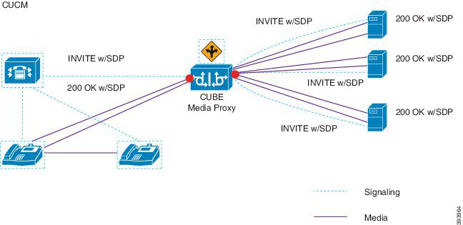
Page 173
The following example illustrates the network-based recording of multi-fork recording through CUBE Media
Proxy.
Figure 5: Network-based recording
For more information on method summary, see "Cisco Device-Specific Extensions" section of Cisco Unified
JTAPI Developers Guide for Cisco Unified Communications Manager Release 12.5(1).
Supported Platforms
Multi-fork recording through CUBE Media Proxy server is supported on the following Cisco Router Platforms
running on Cisco IOS XE Gibraltar Release 16.10.1:
• Cisco 4000 Series-Integrated Services Routers (ISR G3 - ISR4331, ISR4351, ISR4431, ISR4451).
• Cisco Aggregated Services Routers (ASR - ASR1001-X, ASR1002-X, ASR1004 with RP2, ASR1006
with RP2).
• Cisco Cloud Services Routers (CSR1000V series).
Restrictions for Multi-fork recording through CUBE Media Proxy
Multi-fork recording through CUBE Media Proxy server does not support the following:
• Video recording.
• Secure media (SRTP) forking of non secure calls.
• SRTP fall back.
• Midcall block.
Recording Media Source Selection
When you configure network-based recording, you must configure either the phone or the gateway as your
preferred source of recording media for the agent phone line. However, depending on your deployment,
Unified Communications Manager may not select your preferred choice as the recording media source. The
following table displays the logic Unified Communications Manager uses to select the recording media source.
Feature Configuration Guide for Cisco Unified Communications Manager, Release 15 and SUs
131
Monitoring and Recording
Recording Media Source Selection
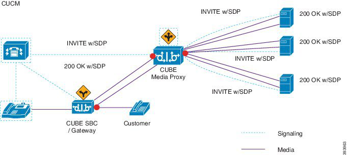
Page 174
Table 18: Recording Media Source Selection
Selected Media Source
Gateway in call path?
Media Type
Preferred Media Source
Gateway
Yes
Unsecure (RTP)
Gateway
Phone
No
Phone
Yes
Secure (sRTP)
Phone
No
Phone
Yes
Unsecure (RTP)
Phone
Phone
No
Phone
Yes
Secure (sRTP)
Phone
No
Alternate Recording Media Source if the First Choice is Unavailable
If the recording media source that Unified Communications Manager selects is unavailable, Unified
Communications Manager attempts to use an alternate source. The following table shows the logic Unified
Communications Manager uses to select an alternate source for recording media.
Table 19: Alternate Recording Media Source if First Choice is Unavailable
Phone Preferred
Gateway Preferred
Selected Media Source
Phone
First gateway in call path
First attempt
First gateway in call path
Last gateway in call path
Second attempt
Last gateway in call path
Phone
Third attempt
Recording Prerequisites
• Cisco Unified IP Phone support—To view a list of the Cisco Unified IP Phone that support recording,
log in to Cisco Unified Reporting and run the Unified CM Phone Feature List report, selecting Record
as the feature. For a detailed procedure, see Generate a Phone Feature List, on page 5.
• Gateway support—For details on which gateways support recording, see https://developer.cisco.com/
web/sip/wiki/-/wiki/Main/Unified+CM+Recording+Gateway+Requirements.
• If you are configuring multiple-stream recording, deploy and configure a CUBE Media Proxy. For details,
see the section CUBE Media Proxy in the Cisco Unified Border Element Configuration Guide.
Feature Configuration Guide for Cisco Unified Communications Manager, Release 15 and SUs
132
Monitoring and Recording
Recording Prerequisites
Page 175
Recording Configuration Task Flow
Before you begin
Procedure
Purpose
Command or Action
Create a recording profile.
Create a Recording Profile, on page 133
Step 1
Optional. Configure the SIP Profile if you want
to deliver the Conference Bridge Identifier to
the recorder.
Configure SIP Profile for Recording, on page
134
Step 2
Configure the recorder server or CUBE Media
Proxy as a SIP trunk device.
Configure SIP Trunks for Recording, on page
134
Step 3
Create a route pattern that routes to the recorder
server or CUBE Media Proxy.
Configure Route Pattern for Recording, on page
135
Step 4
Configure the agent phone line for recording.
Configure Agent Phone Line for Recording, on
page 135
Step 5
To use the agent phone as the recording media
source you must enable the phone's built in
Enable the built in bridge for your agent phones.
Perform one of the following tasks to enable
the built-in-bridge for recording:
Step 6
bridge for recording. You can use a service
parameter to set the built in bridge defaults
• Enable Built in Bridge for Cluster , on
page 136
across the cluster, or enable the built in bridge
on an individual phone.
• Enable Built in Bridge for a Phone, on
page 136
Note
The Built in Bridge setting on individual
phones overrides the clusterwide defaults.
Configure Unified Communications services
on the gateway.
Enable Gateway for Recording, on page 137
Step 7
Configure whether you want a notification tone
to play when calls are recorded.
Configure Recording Notification Tones, on
page 138
Step 8
Configure a Record feature button or softkey
for your phone.
Perform one of the following procedures,
depending on whether your phone uses feature
buttons or softkeys:
Step 9
• Configure a Record Feature Button, on
page 138
• Configure a Record Softkey, on page 139
Create a Recording Profile
Use this procedure to create a recording profile.
Feature Configuration Guide for Cisco Unified Communications Manager, Release 15 and SUs
133
Monitoring and Recording
Recording Configuration Task Flow
Page 176
Procedure
Step 1
From Cisco Unified CM Administration, choose Device > Device Settings > Recording Profile.
Step 2
Click Add New.
Step 3
In the Name field, enter a name for your recording profile.
Step 4
In the Recording Calling Search Space field, select the calling search space that contains the partition with
the route pattern that is configured for the recording server.
Step 5
In the Recording Destination Address field, enter the directory number or the URL of the recording server
or the URL of the CUBE Media Proxy server.
Step 6
Click Save.
Configure SIP Profile for Recording
Use this procedure to deliver the conference bridge identifier to the recorder and configure the SIP Profile.
Procedure
Step 1
From Cisco Unified CM Administration, choose Device > Device Settings > SIP Profile.
Step 2
Select the SIP profile that you want to use for your network.
Step 3
Set a value for the Early Offer Support for Voice and Video calls field. SIP trunk from Unified
Communications Manager to CUBE Media Proxy server must be enabled for an Early Offer support and
configuration options are Best Effort (no MTP inserted) and Mandatory (insert MTP if needed).
Note
We recommend that you enable SIP trunk for Mandatory (insert MTP if needed).
Step 4
Check the Deliver Conference Bridge Identifier check box.
Step 5
Click Save.
Configure SIP Trunks for Recording
Use this procedure to assign the recording server information in the SIP Trunk Configuration window.
Procedure
Step 1
From Cisco Unified CM Administration, choose Device > Trunk.
Step 2
Click Add New.
Step 3
From the Trunk Type drop-down list, choose SIP Trunk.
Feature Configuration Guide for Cisco Unified Communications Manager, Release 15 and SUs
134
Monitoring and Recording
Configure SIP Profile for Recording
Page 177
Device Protocol is auto-populated to SIP, which is the only available option.
Step 4
From the Trunk Service Type drop-down list, choose the service type that you want to use in your network.
The default value is None.
Step 5
Click Next.
Step 6
In the Destination Address field of the SIP Information pane, enter an IP address, fully qualified domain
name, or DNS SRV of the recording server or CUBE Media proxy.
Step 7
From the SIP Profile drop-down list in the SIP Information pane, choose the SIP profile that you want to
use in your network.
Step 8
From the Recording Information pane, select one of the following options:
• None—This trunk is not used for recording.
• This trunk connects to a recording-enabled gateway.
• This trunk connects to other clusters with recording-enabled gateways.
Step 9
Click Save.
Note
SIP trunk from Unified Communications Manager to Media Proxy must be enabled for Early Offer support
in the SIP Profile that is used for this trunk. The configuration options are Mandatory (insert MTP if needed)
and Best Effort (no MTP inserted).
Configure Route Pattern for Recording
Use this procedure to describe the route pattern configurations that are specific to recorders. You must configure
a route pattern that routes to the recording server or CUBE Media Proxy server.
Procedure
Step 1
From Cisco Unified CM Administration, choose Call Routing > Route/Hunt > Route Pattern.
Step 2
Click Add New to create a new route pattern.
Step 3
Complete the fields in the Route Pattern Configuration window.For more information on the fields and
their configuration options, see Online Help.
Step 4
For call recording, complete the following fields:
• Pattern—Enter a pattern that matches the recording destination address from the recording profile.
• Gateway/Route List—Choose the SIP trunk or route list that points to the recording server.
Step 5
Click Save.
Configure Agent Phone Line for Recording
Use this procedure to configure the agent phone line for recording.
Feature Configuration Guide for Cisco Unified Communications Manager, Release 15 and SUs
135
Monitoring and Recording
Configure Route Pattern for Recording
Page 178
Procedure
Step 1
From Cisco Unified CM Administration, choose Device > Phone.
Step 2
Click Find.
Step 3
Select the agent's phone.
Step 4
In the left Association pane, click the phone line for the agent to view the settings.
Step 5
From the Recording Option drop-down list, choose one of the following options:
• Call Recording Disabled—Calls on this phone line are not recorded.
• Automatic Call Recording Enabled—All calls on this phone line are recorded.
• Selective Call Recording Enabled—Only selected calls on this phone line are recorded.
Step 6
From the Recording Profile drop-down list, choose the recording profile that is configured for the agent.
Step 7
From the Recording Media Source drop-down list, choose whether you want to use the gateway or the phone
as the preferred source of recording media.
Step 8
Set the Busy Trigger field to a minimum of 3 if you also have Multilevel Precedence and Preemption (MLPP)
configured.
Step 9
Click Save.
Enable Built in Bridge for Cluster
Use this procedure to enable the phone's built in bridge for recording to use the agent phone as the recording
media source.
When you set the Built-in-Bridge clusterwide service parameter to enable, the Built-in-Bridge default setting
for all phones in the cluster is changed to enabled. However, the Built-in-Bridge setting in the Phone
Configuration window for an individual phone overrides the clusterwide service parameter setting if the
default option is not selected for that phone.
Procedure
Step 1
From Cisco Unified CM Administration, choose System > Service Parameters.
Step 2
From the Server drop-down list, choose the server on which the CallManager service is running.
Step 3
From the Service drop-down list, choose Cisco CallManager.
Step 4
Set the Builtin Bridge Enable service parameter to On.
Step 5
Click Save.
Enable Built in Bridge for a Phone
Use this procedure to enable the Built in Bridge for an individual phone. If the default option is not selected,
the Built in Bridge setting in the Phone Configuration window overrides the clusterwide service parameter.
Feature Configuration Guide for Cisco Unified Communications Manager, Release 15 and SUs
136
Monitoring and Recording
Enable Built in Bridge for Cluster
Page 179
Optionally, use a service parameter to set the Built in Bridge defaults across the cluster. For more information,
see Enable Built in Bridge for Cluster , on page 136.
Procedure
Step 1
From Cisco Unified CM Administration, choose Device > Phone.
Step 2
Click Find to select the agent phone.
Step 3
From the Built in Bridge drop-down list, choose one of the following options:
• On—The Built in Bridge is enabled.
• Off—The Built in Bridge is disabled.
• Default—The setting of the clusterwide Builtin Bridge Enable service parameter is used.
Note
The recording can fail if the Built-in-Bridge is ON and if you check the Media Termination Point Required
check box.
Step 4
Click Save.
Enable Gateway for Recording
Use this procedure to configure the gateway for recording. You must enable Unified Communications Gateway
Services. The following task flow contains the high-level process to enable Unified Communications Gateway
Services.
Procedure
Step 1
Configure Unified Communications Manager IOS Services on the Device.
Step 2
Configure the XMF Provider.
Step 3
Verify Unified Communications Gateway Services.
For detailed configuration steps, including examples, refer to the Cisco Unified Communications Gateway
Services chapter for either of the following documents:
• For more information, see ASR routers Cisco Unified Border Element (Enterprise) Protocol-Independent
Features and Setup Configuration Guide. Cisco IOS XE Release 35.
• For more information, see ISR routers Cisco Unified Border Element Protocol-Independent Features and
Setup Configuration Guide, Cisco IOS Release 15M&T.
Feature Configuration Guide for Cisco Unified Communications Manager, Release 15 and SUs
137
Monitoring and Recording
Enable Gateway for Recording
Page 180
Configure Recording Notification Tones
Use this procedure to configure notification tone to play when calls are recorded. For legal compliance, an
explicit notification in the form of a periodic tone can be made audible to the agent, the caller, or both, to
indicate that a recording session is in progress. This tone can also be disabled.
Recording tone settings override monitoring tone settings when both are enabled for the same call.
Note
Procedure
Step 1
From Cisco Unified CM Administration, choose System > Service Parameters.
Step 2
From the Server drop-down list, choose the server on which the Cisco CallManager service is running.
Step 3
From the Service drop-down list, choose Cisco CallManager.
Step 4
If you want a notification tone to be played to the agent, set the Play Recording Notification Tone to Observed
Target (agent) service parameter to True.
Step 5
If you want a notification tone to be played to the customer, set the value of the Play Recording Notification
Tone To Observed Connected Parties (customer) service parameter to True.
Step 6
Click Save.
Configure a Record Feature Button
Use this procedure to assign the Record feature button to your phone if your phone uses feature buttons.
Procedure
Purpose
Command or Action
Configure a phone button template that includes
the Record button.
Configure a Phone Button Template for
Recording, on page 138
Step 1
Associate the phone button template that you
set up for recording to the phone.
Associate a Phone Button Template with a
Phone, on page 139
Step 2
Configure a Phone Button Template for Recording
Use this procedure to create a phone button template that includes the Record feature button.
Procedure
Step 1
From Cisco Unified CM Administration, choose Device > Device Settings > Phone Button Template.
Step 2
Click Find to display list of supported phone templates.
Feature Configuration Guide for Cisco Unified Communications Manager, Release 15 and SUs
138
Monitoring and Recording
Configure Recording Notification Tones

Page 181
Step 3
Perform the following steps if you want to create a new phone button template; otherwise, proceed to the next
step.
a)
Select a default template for the model of phone and click Copy.
b) In the Phone Button Template Information field, enter a new name for the template.
c)
Click Save.
Step 4
Perform the following steps if you want to add phone buttons to an existing template.
a)
Click Find and enter the search criteria.
b) Choose an existing template.
Step 5
From the Line drop-down list, choose feature that you want to add to the template.
Step 6
Click Save.
Step 7
Perform one of the following tasks:
• Click Apply Config if you modified a template that is already associated with devices to restart the
devices.
• If you created a new softkey template, associate the template with the devices and then restart them.
Associate a Phone Button Template with a Phone
Use this procedure to associate the phone button template that you created for the Record button of the phone.
Procedure
Step 1
From Cisco Unified CM Administration, choose Device > Phone.
Step 2
Click Find to display the list of configured phones.
Step 3
Choose the phone to which you want to add the phone button template.
Step 4
In the Phone Button Template drop-down list, choose the phone button template that contains the new feature
button.
Step 5
Click Save.
A dialog box is displayed with a message to press Reset to update the phone settings.
Configure a Record Softkey
Use this procedure to add a Record softkey to the phone, if your phone uses softkeys. The Record softkey is
only available in the Connected call state for the Cisco Chaperone Phone with Feature Hardkeys template.
Procedure
Purpose
Command or Action
Configure a softkey template that includes the
Record softkey.
Configure a Softkey Template for Recording,
on page 140
Step 1
Feature Configuration Guide for Cisco Unified Communications Manager, Release 15 and SUs
139
Monitoring and Recording
Associate a Phone Button Template with a Phone
Page 182
Purpose
Command or Action
Associate the softkey template to a phone
directly, or to a Common Device Configuration.
Perform one of the following procedure:
Step 2
• Associate a Softkey Template with a
Phone, on page 141
You can then associate the Common Device
Configuration to a group of phones.
• Associate a Softkey Template with a
Common Device Configuration, on page
141
Configure a Softkey Template for Recording
Procedure
Step 1
From Cisco Unified CM Administration, choose Device > Device Settings > Softkey Template.
Step 2
Perform the following steps to create a new softkey template; otherwise, proceed to the next step.
a)
Click Add New.
b) Select a default template and click Copy.
c)
Enter a new name for the template in the Softkey Template Name field.
d) Click Save.
Step 3
Perform the following steps to add softkeys to an existing template.
a)
Click Find and enter the search criteria.
b) Select the required existing template.
Step 4
Check the Default Softkey Template check box to designate this softkey template as the default softkey
template.
Note
If you designate a softkey template as the default softkey template, you cannot delete it unless you first remove
the default designation.
Step 5
Choose Configure Softkey Layout from the Related Links drop-down list in the upper right corner and
click Go.
Step 6
From the Select a Call State to Configure drop-down list, choose the call state for which you want the softkey
to display.
Step 7
From the Unselected Softkeys list, choose the softkey to add and click the right arrow to move the softkey
to the Selected Softkeys list. Use the up and down arrows to change the position of the new softkey.
Step 8
Repeat the previous step to display the softkey in additional call states.
Step 9
Click Save.
Step 10
Perform one of the following tasks:
• Click Apply Config if you modified a template that is already associated with devices to restart the
devices.
Feature Configuration Guide for Cisco Unified Communications Manager, Release 15 and SUs
140
Monitoring and Recording
Configure a Softkey Template for Recording
Page 183
• If you created a new softkey template, associate the template with the devices and then restart them. For
more information, see Add a Softkey Template to a Common Device Configuration and Associate a
Softkey Template with a Phone sections.
Associate a Softkey Template with a Phone
Use this procedure to assign the Record softkey to the phone by associating the softkey template that includes
the Record softkey directly to a phone.
Procedure
Step 1
From Cisco Unified CM Administration, choose Device > Phone.
Step 2
Click Find to select the phone to add the softkey template.
Step 3
From the Softkey Template drop-down list, choose the template that contains the new softkey.
Step 4
Click Save.
Step 5
Press Reset to update the phone settings.
Associate a Softkey Template with a Common Device Configuration
Use this procedure to add a Record softkey to the phone by associating the softkey template to a Common
Device Configuration.
Procedure
Purpose
Command or Action
Add a Softkey Template to the Common Device
Configuration, on page 141
Step 1
Add Common Device Configuration to Phone,
on page 142
Step 2
Add a Softkey Template to the Common Device Configuration
Procedure
Step 1
From Cisco Unified CM Administration, choose Device > Device Settings > Common Device Configuration.
Step 2
Perform the following steps to create a new Common Device Configuration and associate the softkey template
with it; otherwise, proceed to the next step.
a)
Click Add New.
b) Enter a name for the Common Device Configuration in the Name field.
c)
Click Save.
Step 3
Perform the following steps to add the softkey template to an existing Common Device Configuration.
Feature Configuration Guide for Cisco Unified Communications Manager, Release 15 and SUs
141
Monitoring and Recording
Associate a Softkey Template with a Phone
Page 184
a)
Click Find and enter the search criteria.
b) Click an existing Common Device Configuration.
Step 4
In the Softkey Template drop-down list, choose the softkey template that contains the softkey that you want
to make available.
Step 5
Click Save.
Step 6
Perform one of the following tasks:
• If you modified a Common Device Configuration that is already associated with devices, click Apply
Config to restart the devices.
• If you created a new Common Device Configuration, associate the configuration with devices and then
restart them.
Add Common Device Configuration to Phone
Procedure
Step 1
From Cisco Unified CM Administration, choose Device > Phone.
Step 2
Click Find and select the phone device to add the softkey template.
Step 3
From the Common Device Configuration drop-down list, choose the common device configuration that
contains the new softkey template.
Step 4
Click Save.
Step 5
Click Reset to update the phone settings.
Recording Call Flow Examples
For call flow examples for both network-based call recording and IP phone-based call recording use cases,
refer to Call Recording Examples for Network-Based and Phone-Based Recording at the following URL:
https://www.cisco.com/c/en/us/td/docs/voice_ip_comm/cucm/configExamples/cucm_b_recording-use-cases.html
Recording Interactions and Restrictions
Interactions and Restrictions
Feature
Recording Tones take precedence over Monitoring Tones for calls that are both
recorded and monitored. If you configure both, and a call is both recorded and
monitored, only the recording tone plays.
Monitoring Tones
If you also have Multilevel Precedence and Preemption (MLPP) configured, you
must set the Busy Trigger setting on the agent phone line to a minimum of 3.
Multilevel Precedence and
Preemption
Feature Configuration Guide for Cisco Unified Communications Manager, Release 15 and SUs
142
Monitoring and Recording
Add Common Device Configuration to Phone
Page 185
Interactions and Restrictions
Feature
If you configure Secure Tones, the secure tone plays to both call participants at
the outset of a secure call, irrespective of whether Recording Tones are configured.
If you configure both Secure Tones and Recording Tones and the call is secure,
the secure tone plays once at the outset of the call followed by the recording tone.
If you configure Secure Tones, Recording Tones, and Monitoring Tones, and the
call is secured, recorded, and monitored, the secure tone plays once followed by
the recording tone. The monitoring tone does not play.
Secure Tones
Agent - customer calls that are routed through the Customer Voice Portal may
be recorded using the agent phone as the recording source.
Customer Voice Portal
If you are using the gateway as your recording source, you cannot place SIP
proxy servers between Unified Communications Manager and the gateway.
SIP Proxy Servers
Each recording session adds two calls to the Busy Hour Call Completion (BHCC)
rate with a minimal impact on CTI resources.
Busy Hour Call
Completion Rate
When you configure Selective Recording, the Media Sense server does not record
the consult call during a transfer. For example, if a call between an agent and a
customer is being recorded and the agent initiates a transfer to a second agent,
the consult call that takes place between the two agents, before the call being
transferred, is not recorded.
To ensure that the consult call is recorded, the agent must press the ‘Record’
softkey when the consult call starts.
Selective Recording with
Media Sense
To record a call for authenticated phones on the Cisco Unified CM Service
Parameter page, set the Authenticated Phone Recording field to Allow
Recording. The default value is Do Not Allow Recording. Unified
Communications Manager allows call recording for authenticated phones while
using a non secure recorder. In case of secure recorder, recording is allowed only
if the recorder supports a Secure Real-Time Transport protocol (SRTP) fallback.
Recording on
authenticated phones
When recording is enabled, the endpoint advertises a single codec and payload,
and a select and join conference takes place in the Unified Communications
Manager.
Codec locking for auto
recording calls in select
and join conference
Recording Calls Do Not Survive Agent Hold
Recording calls get torn down when the agent puts the call on hold, and they get reestablished when the agent
resumes the call.
Feature Configuration Guide for Cisco Unified Communications Manager, Release 15 and SUs
143
Monitoring and Recording
Recording Interactions and Restrictions
Page 186
Figure 6: Recording Calls Do Not Survive Agent Hold
Feature Configuration Guide for Cisco Unified Communications Manager, Release 15 and SUs
144
Monitoring and Recording
Recording Interactions and Restrictions
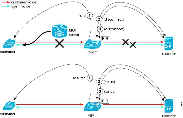
Page 187
P A R T VI
Call Center Features
• Agent Greeting , on page 147
• Auto-Attendant , on page 151
• Manager Assistant , on page 159

Page 188
Page 189
C H A P T E R 14
Agent Greeting
• Agent Greeting Overview, on page 147
• Agent Greeting Prerequisites, on page 147
• Agent Greeting Configuration Task Flow, on page 147
• Agent Greeting Troubleshooting, on page 149
Agent Greeting Overview
Agent Greeting enables Unified Communications Manager to automatically play a prerecorded announcement
following a successful media connection to the agent device. Agent Greeting is audible for the agent and the
customer.
The process of recording a greeting is similar to recording a message for voicemail. Depending on how your
contact center is set up, you can record different greetings that play for different types of callers (for example,
an English greeting for English speakers or an Italian greeting for Italian speakers).
By default, agent greeting is enabled when you log in to your agent desktop but you can turn it off and on as
necessary.
Agent Greeting Prerequisites
• Install Cisco Unified Contact Center Enterprise. See Cisco Unified Contact Center Enterprise Installation
and Upgrade Guide.
• Install Cisco Unified Customer Voice Portal. See Installation and Upgrade Guide for Cisco Unified
Customer Voice Portal .
• Ensure that you enable Built In Bridge. To view the details, see Configure Built In Bridge, on page 149.
Agent Greeting Configuration Task Flow
Agent Greeting configuration tasks are completed in Cisco Unified Contact Center Enterprise (Unified CCE)
and Cisco Unified Customer Voice Portal (Unified CVP). To view detailed steps for the following tasks, see
the Agent Greeting section in the Cisco Unified Contact Center Enterprise Features Guide.
Feature Configuration Guide for Cisco Unified Communications Manager, Release 15 and SUs
147

Page 190
Before you begin
• Review Agent Greeting Prerequisites, on page 147
Procedure
Purpose
Command or Action
Agent Greeting uses the Unified CVP media
server to store and serve prompt and greeting
files.
Configure a media server for Agent Greeting.
Step 1
• Configure a server to act as a media
server.
• Add the media server in Unified CVP.
• Configure the media server to write files.
The .tcl script files that ship with Unified CVP
Release 9.0(1) include updates to support
Republish .tcl scripts to Voice Extensible
Markup Language (VXML) Gateway.
Step 2
Agent Greeting. You must republish these
updated files to your VXML Gateway.
Republishing scripts to the VXML Gateways
is a standard task in Unified CVP upgrades. If
you did not upgrade Unified CVP and
republish the scripts, you must republish the
scripts before you can use Agent Greeting.
To ensure adequate performance, set the size
of the cache on the VXML Gateway to the
Set the cache size on the VXML Gateway.
Step 3
maximum allowed. The maximum size is 100
megabytes; the default is 15 kilobytes. Failure
to set the VXML Gateway cache to its
maximum can result in slowed performance
to increased traffic to the media server.
Create audio files for each of the voice prompts
that agents hear as they record a greeting.
Create voice prompts to record greetings.
Step 4
Complete to record and play agent greetings.
Configure call types.
Step 5
Complete to record and play agent greetings.
Configure a dialed number.
Step 6
Schedule the script.
Step 7
For Agent Greeting record and play scripts to
interact with Unified CVP, Network VRU
scripts are required.
Define network VRU scripts.
Step 8
(Optional) Import sample Agent Greeting
scripts.
Step 9
Modify the Unified CCE call routing scripts
to use the Play Agent Greeting script.
Modify the Unified CCE call routing scripts.
Step 10
Feature Configuration Guide for Cisco Unified Communications Manager, Release 15 and SUs
148
Call Center Features
Agent Greeting Configuration Task Flow
Page 191
Configure Built In Bridge
The Built in Bridge field setting in the Phone Configuration window for an individual phone overrides the
setting for the Builtin Bridge Enable clusterwide service parameter.
Procedure
Step 1
From Cisco Unified CM Administration, choose Device > Phone.
Step 2
Click Find to select the agent phone.
Step 3
From the Built in Bridge drop-down list, choose one of the following options:
• On—The Built in Bridge is enabled.
• Off—The Built in Bridge is disabled.
• Default—The setting of the clusterwide Builtin Bridge Enable service parameter is used.
Step 4
Click Save.
Agent Greeting Troubleshooting
For information about how to troubleshoot Agent Greeting issues, see “Troubleshooting Agent Greeting”
chapter in the Agent Greeting and Whisper Announcement Feature Guide for Cisco Unified Contact Center
Enterprise guide.
Feature Configuration Guide for Cisco Unified Communications Manager, Release 15 and SUs
149
Call Center Features
Configure Built In Bridge
Page 192
Feature Configuration Guide for Cisco Unified Communications Manager, Release 15 and SUs
150
Call Center Features
Agent Greeting Troubleshooting
Page 193
C H A P T E R 15
Auto-Attendant
• Auto-Attendant Overview, on page 151
• Cisco Unity Connection Configuration, on page 152
• Cisco Unified CCX Configuration, on page 156
• Cisco Unity Express Configuration, on page 158
Auto-Attendant Overview
Auto-Attendant allows callers to locate people in your organization without talking to a receptionist. You can
customize the prompts that are played for the caller.
Auto-Attendant works with Unified Communications Manager to receive calls on specific telephone extensions.
The software interacts with the caller and allows the caller to search for and select the extension of the party
(in your organization) that the caller is trying to reach.
Auto-Attendant provides the following functions:
• Answers a call
• Plays a user-configurable welcome prompt
• Plays a main menu prompt that asks the caller to perform one of three actions:
• Press 0 for the operator
• Press 1 to enter an extension number
• Press 2 to spell by name
If the caller chooses to spell by name (by pressing 2), the system compares the letters that are entered
with the names that are configured to the available extensions. One of the following results can
occur:
• If a match exists, the system announces a transfer to the matched user and waits for up to 2
seconds for the caller to press any Dual Tone Multifrequency (DTMF) key to stop the transfer.
If the caller does not stop the transfer, the system performs an explicit confirmation: it prompts
the user for confirmation of the name and transfers the call to the primary extension of that
user.
• If more than one match occurs, the system prompts the caller to choose the correct extension.
• If too many matches occur, the system prompts the caller to enter more characters.
Feature Configuration Guide for Cisco Unified Communications Manager, Release 15 and SUs
151

Page 194
• If no match occurs, that is, if the user presses wrong options, the system prompts that the user
pressed the wrong options and prompts the user to press the correct options.
• When the caller specifies the destination, the system transfers the call.
• If the line is busy or not in service, the system informs the caller accordingly and replays the main menu
prompt.
Auto-Attendant solution can be deployed in three different ways as follows using different Cisco products
that can provide interactive voice response functionality.
• Auto-Attendant using Cisco Unity Connection (CUC); the most widely used Auto-Attendant solution
configuration by customers
• Auto-Attendant using Cisco Unified Contact Center Express (Unified CCX)
• Auto-Attendant using Cisco Unity Express (CUE)
Cisco Unity Connection Configuration
The Cisco Unity Connection server provides Automated-Attendant functionality for both external and internal
callers. An Auto-Attendant allows callers to be automatically transferred to an extension without the intervention
of an operator or receptionist.
Auto-Attendants offer a menu system; it may also allow a caller to reach a live operator by dialing a number,
usually “0”. Multiple Auto-Attendants may be implemented to support individual site locations. Within Cisco
Unity Connection, an Auto-Attendant is a customized application tree structure that is built by creating and
linking multiple Call Handlers together. The Auto-Attendant is defined by entry and exit points, and intermediate
routing decisions based on the callers DTMF input choices.
For more information about Auto-Attendant default behavior and examples, see System Administration Guide
for Cisco Unity Connection.
Cisco Unity Connection Configuration Task Flow
You can use this task flow to configure auto-attendant using Cisco Unity Connection:
Procedure
Purpose
Command or Action
Perform this task on the Cisco Unified CM
Administration. Create a CTI Route Point which
Configure CTI Route Point, on page 153
Step 1
maps to the Direct-Inward Dial (DID) number
of the company (board number).
Call handlers answer calls, greet callers with
recorded prompts, provide callers with
Configure Auto-Attendant System Call Handler,
on page 154
Step 2
information and options, route calls, and take
messages.
Note
Feature Configuration Guide for Cisco Unified Communications Manager, Release 15 and SUs
152
Call Center Features
Cisco Unity Connection Configuration
Page 195
Purpose
Command or Action
You can customize the greeting for the
AutoAttendant Call Handler by choosing
Edit > Greetings. For more information about
customizing greetings, see System
Administration Guide for Cisco Unity
Connection.
Caller input option enables you to designate a
single digit to represent a user extension,
Configure Caller Input Option, on page 154
Step 3
alternate contact number, call handler, interview
handler, or directory handler. The caller presses
a single key during a call handler greeting
instead of entering the full extension, and Cisco
Unity Connection responds accordingly. Several
different keys configured as caller input options
offers the callers a menu of choices in the call
handler greeting.
Configure an extension for the operator to allow
callers to speak to an operator during a call
handler greeting.
Configure Extension for Operator Call Handler,
on page 155
Step 4
Modify the Standard Call Transfer Rule to
enable the call to be transferred to the operator
Modify Standard Call Transfer Rule for
Operator, on page 155
Step 5
when the caller presses 0 to speak to an
operator.
Update the Default System Transfer restriction
table. The Default System Transfer restriction
Update Default System Transfer Restriction
Table, on page 155
Step 6
table restricts numbers that can be used for
Caller system transfers, which allow
unidentified callers to transfer to a number that
they specify.
Configure CTI Route Point
Procedure
Step 1
From Cisco Unified CM Administration, choose Device > CTI Route Point.
Step 2
Click Add New.
Step 3
In the Device Name field, enter a device name for the route point.
Step 4
From the Device Pool drop-down list, choose Default.
Step 5
Click Save.
The Add successful message is displayed.
Step 6
From the Association area, click Line [1] - Add a new DN.
The Directory Number Configuration window is displayed.
Step 7
In the Directory Number field, enter the directory number that matches with the DID of the company.
Feature Configuration Guide for Cisco Unified Communications Manager, Release 15 and SUs
153
Call Center Features
Configure CTI Route Point
Page 196
Step 8
From the Route Partition drop-down list, choose the required route partition.
Step 9
From the Call Forward and Call Pickup Settings area, for Forward All, choose the appropriate calling
search space and check the Voice Mail check box.
Step 10
Click Save.
Configure Auto-Attendant System Call Handler
Procedure
Step 1
From Cisco Unity Connection Administration, from the Cisco Unity Connection tree on the left, navigate to
Call Management and choose System Call Handlers.
Step 2
Click Add New.
The New Call Handler window is displayed.
Step 3
In the Display Name field, enter AutoAttendant.
Step 4
In the Extension field, enter the same extension that you provided for the CTI Route Point.
Step 5
Click Save.
The Edit Call Handler Basics (AutoAttendant) window is displayed.
Step 6
Edit the required fields and click Save.
Configure Caller Input Option
Procedure
Step 1
From Cisco Unity Connection Administration, from the Cisco Unity Connection tree on the left, navigate to
Call Management and choose System Call Handlers.
Step 2
Click AutoAttendant.
The Edit Call Handler Basics (AutoAttendant) window is displayed.
Step 3
Choose Edit > Caller Inputs.
The Caller Input window is displayed.
Step 4
In the Key column, click 0.
The Edit Caller Input (0) window is displayed.
Step 5
Click the Call Handler radio button, choose Operator from the drop-down list, and click the Attempt
Transfer radio button.
Step 6
Click Save.
The Updated Caller Input status message is displayed.
Step 7
Choose Edit > Caller Inputs.
The Caller Input window is displayed.
Step 8
In the Key column, click 1.
The Edit Caller Input (0) window is displayed.
Step 9
In the Conversation radio button, choose Caller System Transfer from the drop-down list.
Feature Configuration Guide for Cisco Unified Communications Manager, Release 15 and SUs
154
Call Center Features
Configure Auto-Attendant System Call Handler
Page 197
Step 10
Click Save.
The Updated Caller Input status message is displayed.
Configure Extension for Operator Call Handler
Procedure
Step 1
From Cisco Unity Connection Administration, from the Cisco Unity Connection tree on the left, navigate to
Call Management and choose System Call Handlers.
Step 2
Click Operator.
The Edit Call Handler Basics (Operator) window is displayed.
Step 3
Enter the extension of the operator in the Extension field and click Save.
The Updated Caller Input status message is displayed.
Modify Standard Call Transfer Rule for Operator
Procedure
Step 1
From Cisco Unity Connection Administration, from the Cisco Unity Connection tree on the left, navigate to
Call Management and choose System Call Handlers.
Step 2
Click Operator.
The Edit Call Handler Basics (Operator) window is displayed.
Step 3
From the Edit menu, choose Transfer Rules.
The Transfer Rules window is displayed.
Step 4
Click Standard.
The Edit Transfer Rule (Standard) window is displayed.
Step 5
In the Transfer Calls to option, click the Extension radio button and enter the configured operator extension
number.
Step 6
Click Save.
Update Default System Transfer Restriction Table
Procedure
Step 1
From Cisco Unity Connection Administration, from the Cisco Unity Connection tree on the left, navigate to
System Settings and choose Restriction Tables.
Step 2
Click Default System Transfer.
The Edit Restriction Table Basics (Default System Transfer) window is displayed.
Feature Configuration Guide for Cisco Unified Communications Manager, Release 15 and SUs
155
Call Center Features
Configure Extension for Operator Call Handler
Page 198
Step 3
Uncheck the check box in the Blocked column for 6 in the Order column.
Step 4
Click Save.
Cisco Unity Connection Auto-Attendant Troubleshooting
For information about troubleshooting Auto-Attendant using Cisco Unity Connection, see the following:
• http://www.cisco.com/c/en/us/support/docs/voice-unified-communications/
unified-communications-manager-callmanager/107517-calltrf.html
• http://www.cisco.com/c/en/us/td/docs/voice_ip_comm/connection/8x/troubleshooting/guide/8xcuctsgx/
8xcuctsg110.html
• http://www.cisco.com/c/en/us/td/docs/voice_ip_comm/connection/8x/troubleshooting/guide/8xcuctsgx/
8xcuctsg040.html
• http://www.cisco.com/c/en/us/td/docs/voice_ip_comm/connection/8x/troubleshooting/guide/8xcuctsgx/
8xcuctsg180.html
Cisco Unified CCX Configuration
Auto-Attendant comes standard with the five-seat bundle of Cisco Unified Contact Center Express (Unified
CCX).
For information about the supported versions of Cisco Unified CCX with Unified Communications Manager,
see Cisco Collaboration Systems Release Summary Matrix for IP Telephony.
Note
For information about getting started with scripts, see the Cisco Unified Contact Center Express Getting
Started with Scripts.
Cisco Unified CCX Prerequisites
• Install and configure Cisco Unified CCX before you can use Auto-Attendant. Cisco Unified CCX controls
the software and its connection to the telephony system.
• Configure users on Unified Communications Manager.
Cisco Unified CCX Auto-Attendant Task Flow
Auto-Attendant configuration tasks are completed in Cisco Unified Contact Center Express (Unified CCX).
To view detailed steps for the following tasks, see Cisco Unified CCX Administration Guide and the Cisco
Unified Contact Center Express Getting Started with Scripts respectively.
Before you begin
• Learn more about the Auto-Attendant feature by reviewing Auto-Attendant Overview, on page 151.
Feature Configuration Guide for Cisco Unified Communications Manager, Release 15 and SUs
156
Call Center Features
Cisco Unity Connection Auto-Attendant Troubleshooting

Page 199
• Learn more about Cisco UCCX with Auto-Attendant functionality by reviewing Cisco Unified CCX
Configuration, on page 156
• Review Cisco Unified CCX Prerequisites, on page 156.
Procedure
Purpose
Command or Action
The Unified CCX system uses Unified CM
Telephony call control groups to pool together
Configure Unified CM Telephony call control
groups.
Step 1
a series of CTI ports, which the system uses to
serve calls as they arrive or depart from the
Unified CCX server.
The Cisco Media subsystem is a subsystem of
the Unified CCX Engine. The Cisco Media
Add a Cisco Media Termination (CMT) dialog
control group.
Step 2
subsystem manages the CMT media resource.
CMT channels are required for Unified CCX
to be able to play or record media.
The Cisco Media subsystem uses dialog groups
to organize and share resources among
applications. A dialog group is a pool of dialog
channels in which each channel is used to
perform dialog interactions with a caller, during
which the caller responds to automated prompts
by pressing buttons on a touch-tone phone.
Caution
All media termination strings begin with “auto”
and contain the same ID as the call control
group—not the CMT dialog group. Perform
this procedure if the default media termination
is configured and the ID differs.
The Unified CCX script applications are
applications that are based on scripts created in
Configure a Cisco script application.
Step 3
the Unified CCX Editor. These applications
come with every Unified CCX system and
executes scripts that are created in the Unified
CCX Editor.
A Unified CM Telephony trigger responds to
calls that arrive on a specific route point by
Provision a Unified CM Telephony trigger.
Step 4
selecting telephony and media resources to
serve the call and invoking an application script
to handle the call.
The Cisco Unified CCX Administration page
allows you to modify any existing
Auto-Attendant instance as necessary.
Customize Auto-Attendant.
Step 5
• Modify an existing Auto-Attendant
instance
Feature Configuration Guide for Cisco Unified Communications Manager, Release 15 and SUs
157
Call Center Features
Cisco Unified CCX Auto-Attendant Task Flow
Page 200
Purpose
Command or Action
Cisco Unified CCX allows you to customize
the Auto-Attendant prompts from the Cisco
• Configure the Auto-Attendant prompts
Unified CCX Administration Media
Configuration window. It allows you to record
the welcome prompt, configure the welcome
prompt, and upload a spoken name.
Cisco Unity Express Configuration
For information about Auto-Attendant Configuration using Cisco Unity Express, see the “Configuring Auto
Attendants” chapter in Cisco Unity Express VoiceMail and Auto Attendant CLI Administrator Guide for 3.0
and Later Versions.
For information about deploying a sample Auto-Attendant script, see “Deployment of sample script aa.aef”
chapter in the Getting Started with Cisco Unified IP IVR.
For information about an Auto-Attendant example, see “Auto Attendant Script Example” chapter in the Cisco
Unity Express Guide to Writing and Editing Scripts for 7.0 and Later Versions.
For information about Auto-Attendant design considerations, see “Auto Attendant Design Considerations”
chapter in the Cisco Unity Express Design Guide.
Cisco Unity Express Auto-Attendant Troubleshooting
For information about Auto-Attendant troubleshooting using Cisco Unity Connection, see the “Troubleshooting
Cisco Unity Express Automated Attendant” in Excerpts from Cisco IP Communications Express: CallManager
Express with Cisco Unity Express.
Feature Configuration Guide for Cisco Unified Communications Manager, Release 15 and SUs
158
Call Center Features
Cisco Unity Express Configuration
Page 201
C H A P T E R 16
Manager Assistant
• Cisco Unified Communications Manager Assistant Overview, on page 159
• Manager Assistant Prerequisites, on page 161
• Manager Assistant Task Flow for Proxy Lines, on page 162
• Manager Assistant Task Flow for Shared Lines, on page 170
• Manager Assistant Interactions, on page 188
• Manager Assistant Restrictions, on page 190
• Cisco Unified Communications Manager Assistant Troubleshooting , on page 191
Cisco Unified Communications Manager Assistant Overview
The Unified Communications Manager Assistant feature is a plug-in that an assistant can use to handle calls
on behalf of a manager, intercept manager calls, and route them appropriately.
Manager Assistant supports up to 3500 managers and 3500 assistants. To accommodate this number of users,
you can configure up to three Manager Assistant applications in one Unified Communications Manager cluster
and assign managers and assistants to each instance of the application.
Manager Assistant supports shared line support and proxy line support.
Manager Assistant Architecture
The Manager Assistant architecture comprises the following:
• Cisco IP Manager Assistant service—After you install Unified Communications Manager, activate
this service from the Cisco Unified Serviceability interface.
• Assistant Console interface—Allows assistants to access the Manager Assistant features on their
computer to handle calls for managers. The Manager Assistant handles calls for an assistant and for as
many as 33 managers.
• Cisco Unified IP Phone interface: Managers and assistants use softkeys and the Cisco Unified IP Phone
Services button to access the Manager Assistant features.
For more information, see chapter Manager Assistant, in Feature Configuration Guide for Cisco Unified
Communications Manager.
Feature Configuration Guide for Cisco Unified Communications Manager, Release 15 and SUs
159

Page 202
Manager Assistant Database Access Architecture
The database stores all Manager Assistant configuration information. When the manager or assistant logs in,
the Cisco IP Manager Assistant service retrieves all data that is related to the manager or assistant from the
database and stores it in memory. The database includes two interfaces:
• Manager interface—The manager phone makes available the manager features except Manager
Configuration. Manager Assistant automatically logs in a manager in to the Cisco IP Manager Assistant
service when the Cisco IP Manager Assistant service starts.
Managers also have access to Unified Communications Manager features such
as Do Not Disturb and Immediate Divert.
Note
• Assistant interface—The assistant accesses the Manager Assistant features by using the Assistant
Console application and the Cisco Unified IP Phone. The Assistant Console, an application, provides
call-control functions such as answer, divert, transfer, and hold. The assistant uses the Assistant Console
to log in and log out, to set up assistant preferences, and to display the Manager Configuration window
that is used to configure manager preferences.
For more information, see chapter Manager Assistant, in Feature Configuration Guide for Cisco Unified
Communications Manager.
Softkeys
Manager Assistant supports the following softkeys:
• Redirect
• Transfer to VoiceMail
• Do Not Disturb
Manager Assistant supports the following softkey templates:
• Standard Manager—Supports manager for proxy mode
• Standard Shared Mode Manager—Supports manager for shared mode
• Standard Assistant—Supports assistant in proxy or shared mode
• Standard User—The system makes call-processing (such as Hold and Dial) softkeys available with the
Standard User template.
Manager Assistant Shared Line Overview
When you configure Manager Assistant in shared line mode, the manager and assistant share a directory
number, for example, 8001. The assistant handles calls for a manager on the shared directory number. When
a manager receives a call on 8001, both the manager phone and the assistant phone ring.
The Manager Assistant features that do not apply to shared line mode include Default Assistant Selection,
Assistant Watch, Call Filtering, and Divert All Calls. An assistant cannot see or access these features on the
Assistant Console application.
Feature Configuration Guide for Cisco Unified Communications Manager, Release 15 and SUs
160
Call Center Features
Manager Assistant Shared Line Overview

Page 203
Manager Assistant Proxy Line Overview
When you configure Manager Assistant in proxy line mode, the assistant handles calls for a manager using a
proxy number. The proxy number is not the directory number for the manager, but is an alternate number
chosen by the system that an assistant uses to handle manager calls. In proxy line mode, a manager and an
assistant have access to all features that are available in Manager Assistant, which include Default Assistant
Selection, Assistant Watch, Call Filtering, and Divert All Calls.
Manager Assistant Prerequisites
• The user must install JRE on a 32 or 64-bit Windows platform before the user upgrades the Manager
Assistant client to a newer version for Releases 11.5(1)SU9, 12.0(1)SU4, and 14 onwards.
Before you perform the upgrade, ensure that you uninstall the Cisco Unified
Communications Manager Assistant client that is currently installed on your
machine. This is applicable from Releases 12.0(1)SU4 and 14 onwards.
Important
• For the Windows 11 platform, the user must install JRE 1.8 on the 64-bit Windows platform before the
user upgrades the Manager Assistant client to a newer version for Release 15SU2 and later.
• Manager Assistant supports the following browsers and platform:
• Unified Communications Manager Assistant Administration and the Assistant Console are supported
on Internet Explorer 11 with Windows 10 and 11 (64 bit), Firefox with Windows 10 and 11 (64 bit)
or later, and Safari with MacOS (10.x) or later.
To run IPMA plug-in on Windows 11 for Unified Communications Manager
Release 15SU1 and earlier versions, you should install the IPMA Release 15
version plug-in to any of these supported OS platforms: Windows 10, Windows
2019, and Windows 2022. You must then copy the installed version of the IPMA
plug-in to Windows 11 and then launch IMPA.
Note
• On a computer running Windows 10 and 11 or Apple MAC OS X, you can open one of the browsers
specified above.
• To display Manager Assistant features in other languages, install the locale installer before you configure
the Manager Assistant.
• The Assistant Console application is supported on computers that run Windows 10 and 11, Windows
2019, and Windows 2022.
• You must configure the phones and users, and associated the devices to the users. In addition, for shared
line appearances between managers and assistants, you must configure the same directory number on
the manager primary line and assistant secondary line.
• To add managers and assistants in bulk, install the Cisco Unified Communications Manager Bulk
Administration Tool. For more information, see the Bulk Administration Guide.
Feature Configuration Guide for Cisco Unified Communications Manager, Release 15 and SUs
161
Call Center Features
Manager Assistant Proxy Line Overview


Page 204
Manager Assistant Task Flow for Proxy Lines
Before you begin
• Review Manager Assistant Prerequisites, on page 161.
Procedure
Purpose
Command or Action
Run the Cisco Unified CM Assistant
Configuration Wizard, on page 162
Step 1
Configure Manager And Assign Assistant For
Proxy Line, on page 168
Step 2
Configure Assistant Line Appearances for
Proxy Line, on page 169
Step 3
The assistant accesses the Unified
Communications Manager Assistant features
Install Assistant Console Plugin, on page 187
Step 4
by using the Assistant Console application and
the Cisco Unified IP Phone. The Assistant
Console provides call-control functions such as
answer, divert, transfer, and hold.
See Cisco Unified Communications Manager
Assistant User Guide for Cisco Unified
Communications Manager.
Configure the manager and Assistant Console
applications.
Step 5
Run the Cisco Unified CM Assistant Configuration Wizard
You can run the Cisco Unified CM Assistant Configuration Wizard to automatically create partitions, calling
search spaces, and route points. The wizard also creates Bulk Administration Tool (BAT) templates for the
manager phones, the assistant phones, and all other user phones. You can use the BAT templates to configure
the managers, assistants, and all other users. For more information about BAT, see Bulk Administration Guide
for Cisco Unified Communications Manager .
Before you begin
Ensure that the configuration wizard runs on the same server (the Unified Communications Manager server)
as the Bulk Administration Tool.
Procedure
Step 1
From Cisco Unified CM Administration, choose Application > Cisco Unified CM Assistant Configuration
Wizard.
Step 2
Click Next to begin the Cisco Unified CM Assistant Configuration wizard process.
Feature Configuration Guide for Cisco Unified Communications Manager, Release 15 and SUs
162
Call Center Features
Manager Assistant Task Flow for Proxy Lines
Page 205
Step 3
In the Partition for Managers window, enter a name, provide a description, and then click Next. Alternatively,
you can accept the default partition name and description.
Step 4
In the Partition for CTI Route Point window, enter a name, provide a description, and then click Next.
Alternatively, you can accept the default CTI route point name.
Step 5
In the Partition for All Users window, enter a name, provide a description and then click Next. Alternatively,
you can accept the default partition name and description for all users.
Step 6
In the Intercom Partition window, enter a name, provide a description, and then click Next. Alternatively,
you can accept the default intercom partition name.
Step 7
In the Assistant Calling Search Space window, enter a name, and provide a description. Alternatively, you
can use the default calling search space name and description.
The Available Partitions and Selected Partitions boxes under the Route Partitions for this Calling Search Space
automatically list Partitions for the Assistant Calling Search Space. You can accept the default values or you
can choose the applicable partition from the Available Partitions box. Use the up and down arrows to move
partitions from one box to the other.
Step 8
Click Next.
Step 9
In the Everyone Calling Search Space window, enter a name, and provide a description. Alternatively, you
can accept the default calling search space name and description for everyone.
The Available Partitions and Selected Partitions boxes under the Route Partitions for this Calling Search Space
automatically list Partitions for the Assistant Calling Search Space. You can accept the default values or you
can choose the applicable partition from the Available Partitions box. Use the up and down arrows to move
partitions from one box to the other.
Step 10
Click Next.
If you have existing calling search spaces that are configured on the system, the Existing Calling Search
Spaces window is displayed; otherwise, proceed to the next step.
Manager Assistant requires that the existing calling search spaces add the prefix Generated_Route Point
and Generated_Everyone partitions. The Available Calling Search Spaces and Selected Calling Search
Spaces boxes automatically list these partitions. Use the up and down arrows to move partitions from one box
to the other.
Note
The prefix that is added to the existing calling search spaces may change if the administrator has changed the
names of the partitions.
Step 11
Click Next.
Step 12
In the CTI Route Point window, enter a name in the CTI route point name field; otherwise, use the default
CTI route point name.
Step 13
From the drop-down list, choose the appropriate device pool.
Step 14
Enter a route point directory number; otherwise, use the default route point directory number.
Step 15
From the drop-down list, choose the appropriate numbering plan and then click Next.
Step 16
In the Phone Services window, enter the primary phone service name; otherwise, use the default Phone
Service name.
Step 17
From the drop-down list, choose the primary Cisco Unified Communications Manager Assistant server or
enter a server name or IP address.
Step 18
Enter the secondary phone service name; otherwise, use the default phone service name.
Step 19
From the drop-down list, choose the secondary Cisco Unified Communications Manager Assistant server or
enter a server name or IP address and then click Next.
The Confirmation window is displayed. It provides all the information that you chose. If the information is
not correct, you can cancel the configuration process or return to the previous configuration windows.
Feature Configuration Guide for Cisco Unified Communications Manager, Release 15 and SUs
163
Call Center Features
Run the Cisco Unified CM Assistant Configuration Wizard
Page 206
Step 20
Click Finish.
Upon completion, a final status window is displayed.
Any errors that the configuration wizard generates is sent to a trace file. Access this file by using the following
CLI command: file get activelog tomcat/logs/ccmadmin/log4j
What to do next
The Cisco Unified CM Assistant Configuration Wizard only creates the Cisco IP Manager Assistant service
parameters. You must enter the remaining service parameters manually. For service parameter information,
see Manager Assistant Service Parameters for Proxy Line, on page 164.
Manager Assistant Service Parameters for Proxy Line
From Cisco Unified CM Administration, choose System > Service Parameters. Choose the server on which
the Cisco IP Manager Assistant service is active and click ? for detailed descriptions.
Description
Setting
Cisco IP Manager Assistant (Active) Parameters
This parameter specifies the IP address of the primary CTIManager that this Cisco IPMA
process calls.
No default value.
CTIManager (Primary) IP
Address
This parameter specifies the IP address of the backup CTIManager that this Cisco IPMA
process calls when primary CTIManager is down.
No default value.
CTIManager (Backup) IP
Address
This parameter specifies the device name of the CTI route point that this Cisco IPMA server
all calls to managers' primary lines for intelligent call routing.
Cisco recommends that you use same CTI route point device for all servers running the IP
must configure the CTI route point device name if any manager or assistant will be configu
mode.
Route Point Device Name for
Proxy Mode
This service parameter specifies the Instance ID of the Application CAPF Profile for the
IPMASecureSysUser that this Manager Assistant will use to open a secure connection to
Configure this parameter if CTIManager Connection Security Flag is enabled.
CAPF Profile Instance Id for
Secure Connection to
CTIManager
Clusterwide Parameters (Parameters that apply to all servers)
Important
Click Advanced to view the hidden parameters.
This parameter specifies the IP address of the primary Cisco IPMA server.
No default value.
Cisco IPMA Server (Primary)
IP Address
This parameter specifies the IP address of the backup Cisco IPMA server. The backup se
IPMA service when the primary IPMA server fails.
No default value.
Cisco IPMA Server (Backup)
IP Address
Feature Configuration Guide for Cisco Unified Communications Manager, Release 15 and SUs
164
Call Center Features
Manager Assistant Service Parameters for Proxy Line
Page 207
Description
Setting
This parameter specifies the TCP/IP port on the Cisco IPMA servers to which the IPMA
will open socket connections. You may change the parameter if a port conflict exists.
Default value: 2912
Cisco IPMA Server Port
This parameter specifies the interval, in seconds, at which the Cisco IPMA server sends
(commonly referred to as heartbeat) to the IPMA Assistant Consoles. The IPMA Assist
failover when they fail to receive heartbeat from the server before the time that is specif
expires.
Default value: 30 seconds
Cisco IPMA Assistant
Console Heartbeat Interval
This parameter specifies the time, in seconds, that the IPMA Assistant Consoles wait t
from the Cisco IPMA server.
Default value: 30 seconds
Cisco IPMA Assistant
Console Request Timeout
This parameter determines whether Cisco IPMA Ring No Answer (RNA) forwarding
values are True (Cisco IPMA forwards unanswered calls to next available assistant) or
does not forward calls).
This parameter works in conjunction with the Cisco IPMA RNA Timeout parameter
after the time that is specified in the Cisco IPMA RNA Timeout parameter. If a voic
specified for the line, unanswered calls that cannot be forwarded to an assistant are sen
this timer expires.
Default value: False
Cisco IPMA RNA Forward
Calls
This parameter determines whether Cisco IPMA Assistant Phone uses an alphanumeric
user ID.
Default value: True
Alpha Numeric UserID
This parameter specifies the time, in seconds, that the Cisco IPMA server waits befor
unanswered call to the next available assistant. This parameter works in conjunction w
RNA Forward Calls parameter; forwarding occurs only if the Cisco IPMA RNA Forw
is set to True.
Default value: 10 seconds
Cisco IPMA RNA Timeout
This parameter determines whether security for the Cisco IP Manager Assistant servic
connection is enabled. If it is enabled, Cisco IPMA opens a secure connection to CTIM
CAPF profile that is configured for the instance ID (as specified in the CAPF Profile
Secure Connection to CTIManager service parameter) for the application user IPM
Default value: Non Secure
To enable security, you must select an instance ID in the CAPF Profile Instance ID for
to CTIManager service parameter.
CTIManager Connection
Security Flag
This parameter determines whether the Cisco Unified IP Manager Assistant applicatio
back to the intended manager if the call fails to reach the selected proxy assistant.
Default value: False
Redirect call to Manager upon
failure to reach Assistant
Feature Configuration Guide for Cisco Unified Communications Manager, Release 15 and SUs
165
Call Center Features
Manager Assistant Service Parameters for Proxy Line
Page 208
Description
Setting
Advanced Clusterwide parameters
Important
Configure unique IP addresses for each pool so that the same Cisco IPMA server IP address does not appear in more tha
This parameter determines whether multiple instances of the Cisco IP Manager Assistant
run for scalability. If it is enabled, Cisco IPMA can run on the other nodes as configured
Pool 3 parameters.
To enable multiple active mode, you must enter the IP addresses of the nodes on which y
the additional instances of Cisco IPMA. Configure the Cisco IP Manager Assistant servic
those nodes.
Default value: False
Enable Multiple Active Mode
If multiple active mode is enabled, this parameter specifies the IP address of the primary Ci
of the second instance of Cisco IPMA.
Configure the Cisco IP Manager Assistant service parameters on this node.
Pool 2: Cisco IPMA Server
(Primary) IP Address
If multiple active mode is enabled, this parameter specifies the IP address of the backup Ci
of the second instance of Cisco IPMA. The backup server provides IPMA service when th
server fails.
Configure the Cisco IP Manager Assistant service parameters on this node.
Pool 2: Cisco IPMA Server
(Backup) IP Address
If multiple active mode is enabled, this parameter specifies the IP address of the primary Ci
of the third instance of Cisco IPMA.
Configure the Cisco IP Manager Assistant service parameters on this node.
Pool 3: Cisco IPMA Server
(Primary) IP Address
If multiple active mode is enabled, this parameter specifies the IP address of the primary Ci
of the third instance of Cisco IPMA. The backup server provides IPMA service when the
server fails.
Configure the Cisco IP Manager Assistant service parameters on this node.
Pool 3: Cisco IPMA Server
(Backup) IP Address
Clusterwide Parameters (Softkey Templates)
Important
Configure these parameters if you want to use the Manager Assistant automatic configuration for managers and assistan
This parameter specifies the assistant softkey template that is assigned to assistant devices d
Configuration. The value that is specified in this parameter is used when the Automatic C
check box is checked on the Cisco IPMA Assistant Configuration page.
Assistant Softkey Template
This parameter specifies the manager softkey template for proxy mode that is assigned to
during Automatic Configuration. This parameter applies only for managers that use proxy
Manager Softkey Template for
Proxy Mode
Clusterwide Parameters (IPMA Device Configuration Defaults for Proxy Mode)
This parameter defines the partition that is assigned to manager lines that IPMA handles on
during Automatic Configuration. Make sure the partition you want to use has already bee
Unified CM Administration. If the Cisco IPMA Configuration Wizard is run, it will pop
This parameter applies only for managers that use proxy mode.
Manager Partition
Feature Configuration Guide for Cisco Unified Communications Manager, Release 15 and SUs
166
Call Center Features
Manager Assistant Service Parameters for Proxy Line
Page 209
Description
Setting
This parameter specifies the partition that is configured on all proxy lines and the interc
devices, as well as the intercom line on manager devices, during Automatic Configur
partition you want to use has already been added to Cisco Unified CM Administration
Configuration Wizard is run, it will populate this value. This parameter applies only
assistants that use proxy mode.
All User Partition
This parameter specifies the calling search space that is configured for manager lines
that IPMA handles and the intercom line, as well as the assistant intercom line on assi
Automatic Configuration. Make sure the calling search space you want to use has alre
Cisco Unified CM Administration. If Cisco IPMA Configuration Wizard is run, it w
value. This parameter applies only for managers or assistants that use proxy mode.
IPMA Calling Search Space
This parameter defines the manager calling search space that is configured on proxy l
devices during Automatic Configuration. This calling search space must be a calling s
already exists in the system. If Cisco IPMA Configuration Wizard is run, it will popu
parameter applies only for assistants that use proxy mode.
Manager Calling Search Space
This parameter defines the IP phone service to which manager/assistant devices will b
Automatic Configuration. If Cisco IPMA Configuration Wizard is run, it will popu
parameter applies only for managers or assistants that use proxy mode.
Cisco IPMA Primary Phone
Service
This parameter defines the secondary IP phone service to which manager or assistant
subscribed during Automatic Configuration. If Cisco IPMA Configuration Wizard is
this value. This parameter applies only for managers or assistants that use proxy mod
Cisco IPMA Secondary Phone
Service
Clusterwide Parameters (Proxy Directory Number Range for Proxy Mode)
This parameter specifies the starting directory number that is used as the starting num
generation of proxy directory numbers during IPMA assistant configuration. After an a
line number is used for an assistant, the next number will be generated for the next as
This parameter applies only for assistants that use proxy mode.
Starting Directory Number
This parameter specifies the ending directory number for automatic generation of prox
during IPMA assistant configuration. Configuration will stop at this number. This par
for assistants that use proxy mode.
Ending Directory Number
Clusterwide Parameters (Proxy Directory Number Range for Proxy Mode)
This parameter specifies the number of characters to be stripped from the manager dir
in the process of generating the proxy DN. Generating a proxy DN may involve stripp
digits and adding a prefix. Digits are stripped starting from the left. This parameter appli
that use proxy mode.
Number of Characters to be
Stripped from Manager DN
This parameter specifies the prefix to be added to a manager DN in the process of gen
DN. Generating a proxy DN may involve some stripping of digits and adding a prefix
applies only for assistants that use proxy mode.
Prefix for Manager DN
Feature Configuration Guide for Cisco Unified Communications Manager, Release 15 and SUs
167
Call Center Features
Manager Assistant Service Parameters for Proxy Line
Page 210
Configure Manager And Assign Assistant For Proxy Line
For information about configuring a new user and associating a device to the user, see Administration Guide
for Cisco Unified Communications Manager.
Make sure you configure manager information before you configure assistant information for an assistant.
Note
Procedure
Step 1
From Cisco Unified CM Administration, choose User Management > End User.
Step 2
Click Find.
The search result displays all the end users that are configured in Unified Communications Manager.
Step 3
From the Related Links drop-down list, choose Manager Configuration and click Go.
Tip
To view existing assistant configuration information, click the assistant name in the Associated Assistants list
and click View Details. The Cisco Unified CM Assistant - Assistant Configuration window is displayed.
To return to the manager configuration information, click the manager name in the Associated Managers list
and click View Details.
The Cisco Unified CM Assistant - Manager Configuration window is displayed.
Step 4
From the Device Name/Profile drop-down list, choose the device name or device profile to associate a device
name or device profile with a manager. For more information about Extension Mobility with Manager Assistant,
see Manager Assistant Interactions, on page 188.
Note
If the manager telecommutes, click the Mobile Manager check box and optionally choose a device profile
from the Device Name/Profile drop-down list. After you choose a device profile, the manager must log in to
the phone by using extension mobility before accessing Manager Assistant.
Step 5
From the Intercom Line drop-down list, choose the intercom line appearance for the manager, if applicable.
Note
The chosen intercom line applies to the Manager Assistant and Unified Communications Manager intercom
features.
Step 6
From the Assistant Pool drop-down list, choose the appropriate pool number (1 to 3).
Step 7
From the Available Lines selection box, choose a line that you want Manager Assistant to control and click
the down arrow to make the line display in the Selected Lines selection box. Configure up to five Manager
Assistant—controlled lines.
Tip
To remove a line from the Selected Lines selection box and from Manager Assistant control, click the up
arrow.
Step 8
Check the Automatic Configuration check box to automatically configure the softkey template, subscribe
to the Manager Assistant phone service, calling search space, and partition for Manager Assistant—Controlled
selected lines and intercom line; and Auto Answer with Speakerphone for intercom line for the manager phone
based on the Cisco IP Manager Assistant service parameters.
Feature Configuration Guide for Cisco Unified Communications Manager, Release 15 and SUs
168
Call Center Features
Configure Manager And Assign Assistant For Proxy Line

Page 211
Note
Automatic Configuration for intercom applies only when using the Manager Assistant intercom feature for
the Cisco Unified IP Phones 7940 and 7960.
Step 9
Click Save.
If you checked the Automatic Configuration check box and the service parameters are invalid, a message
displays. Ensure that the service parameters are valid. Upon successful completion of the automatic
configuration, the manager device resets. If you configured a device profile, the manager must log out and
log in to the device for settings to take effect.
Configure Assistant Line Appearances for Proxy Line
A proxy line specifies a phone line that appears on the assistant Cisco Unified IP Phone. Manager Assistant
uses proxy lines to manage calls that are intended for a manager. The administrators can manually configure
a line on the assistant phone to serve as the proxy line, or you can enable the Automatic Configuration check
box to generate a DN and to add the line to the assistant phone.
1.
Make sure that you configure manager information and assign an assistant to the manager before you
configure assistant information for an assistant.
2.
If you want to automatically configure proxy line on the assistant phone, configure the service parameters
in Proxy Directory Number Range and Proxy Directory Number Prefix sections.
Note
Procedure
Step 1
From Cisco Unified CM Administration, choose User Management > End User.
Step 2
Click Find.
Step 3
Click on the user name to display user information for the chosen assistant
The End User Configuration window is displayed.
Step 4
From the Related Links drop-down list, choose Assistant Configuration and click Go.
Note
The system automatically sets the softkey template and intercom line on the basis of the Cisco IP Manager
Assistant service parameter settings when the Automatic Configuration check box is checked. In addition,
the system also sets Auto Answer with Speakerphone for intercom line.
The Assistant Configuration window is displayed.
Step 5
From the Device Name drop-down list, choose the device name to associate with the assistant.
Step 6
From the Intercom Line drop-down list, choose the incoming intercom line appearance for the assistant.
Step 7
From the Primary Line drop-down list, choose the primary line for the assistant.
Step 8
To associate the manager line to the assistant line, perform the following steps from the Manager Association
to Assistant Line selection box:
a)
From the Available Lines drop-down list, choose the assistant line that will be associated with the manager
line.
Feature Configuration Guide for Cisco Unified Communications Manager, Release 15 and SUs
169
Call Center Features
Configure Assistant Line Appearances for Proxy Line

Page 212
b) From the Manager Names drop-down list, choose the preconfigured manager name for whom this proxy
line will apply.
c)
From the Manager Lines drop-down list, choose the manager line for which this proxy line will apply.
Step 9
Click Save.
The update takes effect immediately. If you chose Automatic Configuration, the assistant device automatically
resets.
Manager Assistant Task Flow for Shared Lines
Before you begin
• Review Manager Assistant Prerequisites, on page 161.
Procedure
Purpose
Command or Action
Configure a partition for lines that is used by
Manager Assistant.
Configure Partitions for Manager Assistant
Shared Line Support, on page 171
Step 1
Configure calling search spaces for manager
and assistant lines.
Configure Calling Search Spaces for Manager
Assistant Shared Line Support, on page 172
Step 2
Configure these parameters to use automatic
configuration for managers and assistants.
Configure Cisco IP Manager Assistant Service
Parameters, on page 173
Step 3
Configure intercom settings.
Step 4
• Configure an Intercom Partition, on page
174
• Configure an Intercom Calling Search
Space, on page 313
• Configure an Intercom Directory Number,
on page 314
• Configure an Intercom Translation
Pattern, on page 314
Configure multiple pools if you need to support
a large number of managers and assistants.
Configure Multiple Manager Assistant Pool,
on page 176
Step 5
You can configure up to three active Cisco IP
Manager Assistant servers, with each
managing up to 2500 pairs of managers and
assistants.
Follow these procedures if your system is
running in mixed mode.
Configure Secure TLS Connection to CTI
Step 6
• Configure IPMASecureSysUser
Application User, on page 178
• Configure CAPF Profile, on page 178
Feature Configuration Guide for Cisco Unified Communications Manager, Release 15 and SUs
170
Call Center Features
Manager Assistant Task Flow for Shared Lines
Page 213
Purpose
Command or Action
• Configure Cisco WebDialer Web Service
, on page 180
Cisco Unified Communications Manager
Assistant requires creation of CTI route point
to intercept and route calls from managers.
Configure CTI Route Point, on page 180
Step 7
Configure IP Phone Services for Manager and
Assistant, on page 181
Step 8
Configure Phone Button Templates for
Manager, Assistant, and Everyone, on page
184
Step 9
Configure Manager and Assign Assistant for
Shared Line Mode, on page 185
Step 10
Configure Assistant Line Appearances for
Shared Line, on page 186
Step 11
The assistant accesses the Cisco Unified
Communications Manager Assistant features
Install Assistant Console Plugin, on page 187
Step 12
by using the Assistant Console application and
the Cisco Unified IP Phone. The Assistant
Console provides call-control functions such
as answer, divert, transfer, and hold.
See Cisco Unified Communications Manager
Assistant User Guide for Cisco Unified
Communications Manager.
Configure the manager and assistant console
applications.
Step 13
Configure Partitions for Manager Assistant Shared Line Support
You must create three partitions: Generated_Everyone, Generated_Managers, and Generated_Route_Point.
Procedure
Step 1
From Cisco Unified CM Administration, choose Call Routing > Class of Control > Partition.
Step 2
Click Add New to create a new partition.
Step 3
In the Partition Name, Description field, enter a name for the partition that is unique to the route plan.
Partition names can contain alphanumeric characters, as well as spaces, hyphens (-), and underscore characters
(_). See the online help for guidelines about partition names.
Step 4
Enter a comma (,) after the partition name and enter a description of the partition on the same line.
The description can contain up to 50 characters in any language, but it cannot include double quotes ("),
percentage sign (%), ampersand (&), backslash (), angle brackets (<>), or square brackets ([ ]).
If you do not enter a description, Cisco Unified Communications Manager automatically enters the partition
name in this field.
Step 5
To create multiple partitions, use one line for each partition entry.
Feature Configuration Guide for Cisco Unified Communications Manager, Release 15 and SUs
171
Call Center Features
Configure Partitions for Manager Assistant Shared Line Support
Page 214
Step 6
From the Time Schedule drop-down list, choose a time schedule to associate with this partition.
The time schedule specifies when the partition is available to receive incoming calls. If you choose None, the
partition remains active at all times.
Step 7
Select one of the following radio buttons to configure the Time Zone:
• Originating Device—When you select this radio button, the system compares the time zone of the calling
device to the Time Schedule to determine whether the partition is available is available to receive an
incoming call.
• Specific Time Zone—After you select this radio button, choose a time zone from the drop-down list.
The system compares the chosen time zone to the Time Schedule to determine whether the partition is
available is available to receive an incoming call.
Step 8
Click Save.
Partition Name Guidelines for Manager Assistant Shared Line Support
The list of partitions in a calling search space is limited to a maximum of 1024 characters. This means that
the maximum number of partitions in a CSS varies depending on the length of the partition names. Use the
following table to determine the maximum number of partitions that you can add to a calling search space if
partition names are of fixed length.
Table 20: Partition Name Guidelines
Maximum Number of Partitions
Partition Name Length
340
2 characters
256
3 characters
204
4 characters
172
5 characters
...
...
92
10 characters
64
15 characters
Configure Calling Search Spaces for Manager Assistant Shared Line Support
A calling search space is an ordered list of route partitions that are typically assigned to devices. Calling search
spaces determine the partitions that calling devices can search when they are attempting to complete a call.
You must create two calling search spaces: Generated_CSS_I_E and Generated_CSS_M_E.
Procedure
Step 1
From Cisco Unified CM Administration, choose Call Routing > Class of Control > Calling Search Space.
Feature Configuration Guide for Cisco Unified Communications Manager, Release 15 and SUs
172
Call Center Features
Partition Name Guidelines for Manager Assistant Shared Line Support
Page 215
Step 2
Click Add New.
Step 3
In the Name field, enter a name.
Ensure that each calling search space name is unique to the system. The name can include up to 50 alphanumeric
characters and can contain any combination of spaces, periods (.), hyphens (-), and underscore characters (_).
Step 4
In the Description field, enter a description.
The description can include up to 50 characters in any language, but it cannot include double-quotes ("),
percentage sign (%), ampersand (&), back-slash (), or angle brackets (<>).
Step 5
From the Available Partitions drop-down list, perform one of the following steps:
• For a single partition, select that partition.
• For multiple partitions, hold down the Control (CTRL) key, then select the appropriate partitions.
Step 6
Select the down arrow between the boxes to move the partitions to the Selected Partitions field.
Step 7
(Optional) Change the priority of selected partitions by using the arrow keys to the right of the Selected
Partitions box.
Step 8
Click Save.
Configure Cisco IP Manager Assistant Service Parameters
Configure Cisco IP Manager Assistant service parameters if you want to use the Manager Assistant automatic
configuration for managers and assistants. You must specify the cluster-wide parameters once for all Cisco
IP Manager Assistant services and general parameters for each Cisco IP Manager Assistant service that is
installed.
Procedure
Step 1
From Cisco Unified CM Administration, choose System > Service Parameters.
Step 2
From the Server drop-down list, choose the server on which the Cisco IP Manager Assistant service is active.
Step 3
From the Service drop-down list, choose Cisco IP Manager Assistant service.
The Service Parameter Configuration window, which lists the parameters, is displayed.
Step 4
Configure the Cisco IP Manager Assistant Parameters, Clusterwide Parameters (Parameters that apply
to all servers), and Clusterwide Parameters (Softkey Templates).
click ? for detailed descriptions.
Step 5
Click Save.
Feature Configuration Guide for Cisco Unified Communications Manager, Release 15 and SUs
173
Call Center Features
Configure Cisco IP Manager Assistant Service Parameters
Page 216
Configure Intercom Settings
Procedure
Purpose
Command or Action
Configure an Intercom Partition, on page 174
Step 1
Configure an Intercom Calling Search Space,
on page 175
Step 2
Configure an Intercom Directory Number, on
page 175
Step 3
Configure an Intercom Translation Pattern, on
page 176
Step 4
Configure an Intercom Partition
Procedure
Step 1
From Cisco Unified CM Administration, choose Call Routing > Intercom > Intercom Route Partition.
The Find and List Intercom Partitions window appears.
Step 2
Click Add New.
An Add New Intercom Partition window appears.
Step 3
Under the Intercom Partition Information section, in the Name box, enter the name and description of the
intercom partition that you want to add.
Note
To enter multiple partitions, use one line for each partition entry. You can enter up to 75 partitions; the names
and descriptions can have up to a total of 1475 characters. The partition name cannot exceed 50 characters.
Use a comma (,) to separate the partition name and description on each line. If a description is not entered,
Unified Communications Manager uses the partition name as the description.
Step 4
Click Save.
Step 5
Locate the partition that you want to configure.
Intercom Partition Configuration window is displayed
Step 6
Configure the fields in the Intercom Partition Configuration field area. See the online help for more information
about the fields and their configuration options.
Step 7
Click Save.
The Intercom Partition Configuration window appears.
Step 8
Enter the appropriate settings. For detailed information about the Intercom Partition Configuration parameters,
see online help.
Step 9
Click Save.
Feature Configuration Guide for Cisco Unified Communications Manager, Release 15 and SUs
174
Call Center Features
Configure Intercom Settings
Page 217
Step 10
Click Apply Config.
Configure an Intercom Calling Search Space
Procedure
Step 1
In the menu bar, choose Call Routing > Intercom > Intercom Calling Search Space.
Step 2
Click the Add New.
Step 3
Configure the fields in the Intercom Calling Search Space field area. For more information on the fields and
their configuration options, see Online Help.
Step 4
Click Save.
Configure an Intercom Directory Number
Procedure
Step 1
Choose Call Routing > Intercom > Intercom Directory Number.
The Find and List Intercom Directory Numbers window is displayed.
Step 2
To locate a specific intercom directory number, enter search criteria and click Find.
A list of intercom directory numbers that match the search criteria displayed.
Step 3
Perform one of the followings tasks:
a)
To add an intercom directory number, click Add New.
b) To update an intercom directory number, click the intercom directory number to update.
The Intercom Directory Number Configuration window displayed.
Step 4
Configure the fields in the Intercom Directory Number Configuration field area. For more information on the
fields and their configuration options, see Online Help.
Step 5
Click Save.
Step 6
Click Apply Config.
Step 7
Click Reset Phone.
Step 8
Restart devices.
During the restart, the system may drop calls on gateways.
Feature Configuration Guide for Cisco Unified Communications Manager, Release 15 and SUs
175
Call Center Features
Configure an Intercom Calling Search Space
Page 218
Configure an Intercom Translation Pattern
Procedure
Step 1
Choose Call Routing > Intercom > Intercom Translation Pattern.
The Find and List Intercom Translation Patterns window appears.
Step 2
Perform one of the followings tasks:
a)
To copy an existing intercom translation pattern, locate the partition to configure, click Copy eside the
intercom translation pattern to copy.
b) To add a new intercom translation pattern, click the Add New.
Step 3
Configure the fields in the Intercom Translation Pattern Configuration field area. For more information on
the fields and their configuration options, see Online Help.
Step 4
Click Save.
Ensure that the intercom translation pattern that uses the selected partition, route filter, and numbering plan
combination is unique. if you receive an error that indicates duplicate entries, check the route pattern or hunt
pilot, translation pattern, directory number, call park number, call pickup number, or meet-me number
configuration windows.
The Intercom Translation Pattern Configuration window displays the newly configured intercom translation
pattern.
What to do next
Refer to the Manager Assistant Task Flow for Shared Lines, on page 170 to determine the next task to complete.
Configure Multiple Manager Assistant Pool
Procedure
Step 1
From Cisco Unified CM Administration, choose System > Service Parameters.
Step 2
From the Server drop-down list, choose the server on which the Cisco IP Manager Assistant service is active.
Step 3
From the Service drop-down list, choose the Cisco IP Manager Assistant service.
The Service Parameter Configuration window, which lists the parameters, is displayed.
Step 4
Click Advanced.
The advanced parameters for Clusterwide Parameters (Parameters that apply to all servers) are displayed.
Step 5
Configure the following parameters to add multiple manager assistant pools in Clusterwide Parameters
(Parameters that apply to all servers):
a)
Enable Multiple Active Mode—The default is False. When this parameter is set to True, the administrator
can configure up to 7000 managers and assistants by using multiple pools.
b) Pool 2: Cisco IPMA Server (Primary) IP Address—No default. The administrator must manually enter
this IP address. Administrator can assign up to 2500 managers and assistants to this address.
Feature Configuration Guide for Cisco Unified Communications Manager, Release 15 and SUs
176
Call Center Features
Configure an Intercom Translation Pattern
Page 219
c)
Pool 2: Cisco IPMA Server (Backup) IP Address—No default. The administrator must manually enter
this IP address.
d) Pool 3: Cisco IPMA Server (Primary) IP Address—No default. The administrator must manually enter
this IP address and can assign up to 2500 managers and assistants to this address.
e)
Pool 3: Cisco IPMA Server (Backup) IP Address—No default. The administrator must manually enter
this IP address.
click ? for detailed descriptions.
Step 6
Click Save.
What to do next
Refer to the Manager Assistant Task Flow for Shared Lines, on page 170 to determine the next task to complete.
Configure Secure TLS Connection to CTI for Manager Assistant
Manager Assistant uses WDSecureSysUser application user credentials to establish a secure TLS connection
to CTI to make calls.
To configure the WDSecureSysUser application user to establish a secure TLS connection, complete the
following tasks.
Before you begin
• Install and configure the Cisco CTL Client.
For more information about CTL Client, see Security Guide for Cisco Unified Communications Manager.
• Verify that the Cluster Security Mode in the Enterprise Parameters Configuration window is 1
(mixed mode). Operating the system in mixed mode impacts other security functions in your system. If
your system is not currently running in mixed mode, do not switch to mixed mode until you understand
these interactions. For more information, see Security Guide for Cisco Unified Communications Manager.
• Verify that the Cluster SIPOAuth Mode field in the Enterprise Parameters Configuration window
is set to Enabled.
• Activate the Cisco Certificate Authority Proxy Function (CAPF) service on the first node.
Procedure
Purpose
Command or Action
Configure IPMASecureSysUser Application
User.
Configure IPMASecureSysUser Application
User, on page 178
Step 1
Configure Certificate Authority Proxy Function
(CAPF) Profile for the IPMASecureSysUser
Application User.
Configure CAPF Profile, on page 178
Step 2
Configure service parameters for the Cisco IP
Manager Assistant service.
Configure Cisco WebDialer Web Service , on
page 180
Step 3
Feature Configuration Guide for Cisco Unified Communications Manager, Release 15 and SUs
177
Call Center Features
Configure Secure TLS Connection to CTI for Manager Assistant
Page 220
Configure IPMASecureSysUser Application User
Use this procedure to configure IPMASecureSysUser application user.
Procedure
Step 1
From Cisco Unified CM Administration, choose User Management > Application User.
Step 2
Click Find.
Step 3
From the Find and List Application Users Application window, choose WDSecureSysUser.
Step 4
Configure the fields in the Application User Configuration window and click Save.
Configure CAPF Profile
Certificate Authority Proxy Function (CAPF) is a component that performs tasks to issue and authenticate
security certificates. When you create an application user CAPF profile, the profile uses the configuration
details to open secure connections for the application.
Procedure
Step 1
From Cisco Unified CM Administration, choose User Management > Application User CAPF Profile.
Step 2
Perform one of the following tasks:
• Click Add New in the Find window, to add a new CAPF profile.
• Click Copy for that record in the Copy column, to copy an existing profile, and locate the appropriate
profile.
To update an existing entry, locate and display the appropriate profile.
Step 3
Configure or update the relevant CAPF profile fields. See the Related Topics section information about the
fields and their configuration options.
Step 4
Click Save.
Step 5
Repeat the procedure for each application and end user that you want to use security.
CAPF Profile Settings
Description
Setting
From the drop-down list, choose the application user for the CAPF operation.
This setting displays configured application users.
This setting does not appear in the End User CAPF Profile window.
Application User
From the drop-down list, choose the end user for the CAPF operation. This setting
displays configured end users.
This setting does not appear in the Application User CAPF Profile window.
End User ID
Feature Configuration Guide for Cisco Unified Communications Manager, Release 15 and SUs
178
Call Center Features
Configure IPMASecureSysUser Application User
Page 221
Description
Setting
Enter 1 to 128 alphanumeric characters (a-z, A-Z, 0-9). The Instance ID identifies
the user for the certificate operation.
You can configure multiple connections (instances) of an application. To secure
the connection between the application and CTIManager, ensure that each instance
that runs on the application PC (for end users) or server (for application users)
has a unique certificate.
This field relates to the CAPF Profile Instance ID for Secure Connection to
CTIManager service parameter that supports web services and applications.
Instance ID
From the drop-down list, choose one of the following options:
• No Pending Operation—This message is displayed when no certificate
operation is occurring. (default setting)
• Install/Upgrade—This option installs a new certificate or upgrades an
existing locally significant certificate for the application.
Certificate Operation
The authentication mode for the Install/Upgrade certificate operation specifies
By Authentication String, which means CAPF installs, upgrades, or troubleshoots
a locally significant certificate only when the user or administrator enters the
CAPF authentication string in the JTAPI/TSP Preferences window.
Authentication Mode
To create your own authentication string, enter a unique string.
Each string must contain 4 to 10 digits.
To install or upgrade a locally significant certificate, the administrator must enter
the authentication string in the JTAPI/TSP preferences GUI on the applicationPC.
This string supports one-time use only; after you use the string for the instance,
you cannot use it again.
Authentication String
To automatically generate an authentication string, click this button. The 4-
to10-digit authentication string appears in the Authentication String field.
Generate String
From the drop-down list, choose the key size for the certificate. The default setting
is 1024. The other option for key size is 512.
Key generation, which is set at low priority, allows the application to function
while the action occurs. Key generation may take up to 30 or more minutes.
Key Size (bits)
This field, which supports all certificate operations, specifies the date and time
by which you must complete the operation.
The values that are displayed apply for the first node.
Use this setting with the CAPF Operation Expires in (days) enterprise parameter,
which specifies the default number of days in which the certificate operation
must be completed. You can update this parameter at any time.
Operation Completes by
This field displays the progress of the certificate operation, such as pending,
failed, or successful.
You cannot change the information that is displayed in this field.
Certificate Operation
Status
Feature Configuration Guide for Cisco Unified Communications Manager, Release 15 and SUs
179
Call Center Features
CAPF Profile Settings
Page 222
Configure Cisco WebDialer Web Service
Procedure
Step 1
From Cisco Unified CM Administration, choose System > Service Parameters.
Step 2
From the Server drop-down list, choose the server on which the Cisco WebDialer Web service is active.
Step 3
From the Service drop-down list, choose the Cisco WebDialer Web service.
A list of parameters appears.
Step 4
Navigate to and update the CTIManager Connection Security Flag and CAPF Profile Instance ID for Secure
Connection to CTIManager parameters.
To view parameter descriptions, click the parameter name link.
Note
CTIManager supports IPv4 and IPv6 addresses.
Step 5
Click Save.
Step 6
Repeat the procedure on each server on which the service is active.
What to do next
Refer to the Manager Assistant Task Flow for Shared Lines, on page 170 to determine the next task to complete.
Configure CTI Route Point
Procedure
Step 1
From Cisco Unified CM Administration, choose Device > CTI Route Point.
Step 2
Click Add New.
The CTI Route Point Configuration window is displayed.
Step 3
In the Device Name field, enter the device name.
Step 4
From the Device Pool drop-down list, choose Default.
Step 5
From the Calling Search Space drop-down list, choose Generated_CSS_M_E.
Step 6
Check the Use Device Pool Calling Party Transformation CSS check box.
Step 7
Click Save.
Add successful status message is displayed.
Step 8
From the Association area, click Line [1] - Add a new DN.
The Directory Number Configuration window is displayed.
Step 9
Enter a directory number in the Directory Number field.
Step 10
From the Route Partition drop-down list, choose Generated_Route_Point.
Step 11
Click Save.
Feature Configuration Guide for Cisco Unified Communications Manager, Release 15 and SUs
180
Call Center Features
Configure Cisco WebDialer Web Service
Page 223
Configure IP Phone Services for Manager and Assistant
Procedure
Step 1
From Cisco Unified CM Administration, choose Device > Device Settings > Phone Services.
Step 2
Click Add New.
The IP Phone Services Configuration window is displayed.
Step 3
For each supported phone for managers and assistants, enter the required fields and click Save. See Cisco IP
Phone Services Configuration Fields, on page 181 for more information about the fields and their configuration
options.
The Update successful message is displayed.
Cisco IP Phone Services Configuration Fields
Description
Field
Service Information
Enter the name of the service. If the service is not marked as an enterprise
subscription, the service name will display in areas where you can subscribe
to a service, for example, under Cisco Unified Communications Self Care
Portal.
Enter up to 128 characters for the service name.
For Java MIDlet services, the service name must exactly match the name that
is defined in the Java Application Descriptor (JAD) file.
Note
Unified Communications Manager allows you to create two or more IP phone
services with identical names. Cisco recommends that you do not do so unless
most or all phone users are advanced, or unless an administrator always
configures the IP phone services. Be aware that if AXL or any third-party
tool accesses the list of IP phone services for configuration, you must use
unique names for IP phone services.
Note
When the service URL points to an external customized URL, you cannot
localize the service name according to the device locale of the phone. The
service name gets displayed in English alphabets only.
Service Name
Enter the name of the service to display if the phone cannot display Unicode.
ASCII Service Name
Enter a description of the content that the service provides. The description
can include up to 50 characters in any language, but it cannot include double
quotation marks (") or single quotation marks (').
Service Description
Feature Configuration Guide for Cisco Unified Communications Manager, Release 15 and SUs
181
Call Center Features
Configure IP Phone Services for Manager and Assistant
Page 224
Description
Field
Enter the URL of the server where the IP phone services application is located.
Make sure that this server remains independent of the servers in your Unified
Communications Manager cluster. Do not specify a Unified Communications
Manager server or any server that is associated with Unified Communications
Manager (such as a TFTP server or directory database publisher server).
For the services to be available, the phones in the Unified Communications
Manager cluster must have network connectivity to the server.
For Cisco-signed Java MIDlets, enter the location where the JAD file can be
downloaded; for example, a web server or the back-end application server to
which the Java MIDlet communicates.
For Cisco-provided default services, the service URL is displayed as
Application:Cisco/<name of service> by default; for example,
Application:Cisco/CorporateDirectory. If you modify the
service URL for Cisco-provided default services, verify that you configured
both for the Service Provisioning setting, which displays in the Phone,
Enterprise Parameter, and Common Phone Profile Configuration windows.
For example, you use a custom corporate directory, so you change
Application:Cisco/CorporateDirectory to the external service
URL for your custom directory; in this case, change the Service Provisioning
value to Both.
Service URL
Enter the secure URL of the server where the Cisco Unified IP Phone services
application is located. Make sure that this server remains independent of the
servers in your Unified Communications Manager cluster. Do not specify a
Unified Communications Manager server or any server that is associated with
Unified Communications Manager (such as a TFTP server or publisher database
server).
For the services to be available, the phones in the Unified Communications
Manager cluster must have network connectivity to the server.
Note
If you do not provide a Secure-Service URL, the device uses the nonsecure
URL. If you provide both a secure URL and a nonsecure URL, the device
chooses the appropriate URL, based on its capabilities.
Secure-Service URL
Choose a service application type (XML or Java MIDlet).
If you choose Java MIDlet, when the phone receives the updated configuration
file, the phone retrieves the Cisco-signed MIDlet application (JAD and JAR)
from the specified Service URL and installs the application.
Service Category
Choose whether the service is provisioned to the Services, Directories, or
Messages button or option on the phone; that is, if the phone has these buttons
or options. To determine whether your phone supports these buttons or options,
see the Cisco Unified IP Phone Administration Guide that supports your phone
model.
Service Type
Feature Configuration Guide for Cisco Unified Communications Manager, Release 15 and SUs
182
Call Center Features
Cisco IP Phone Services Configuration Fields
Page 225
Description
Field
Allows you to specify the vendor or manufacturer for the service. This field
is optional for XML applications, but it is required for Cisco-signed Java
MIDlets.
For Cisco-signed Java MIDlets, the value that you enter in this field must
exactly match the vendor that is defined in the MIDlet JAD file.
This field displays as blank for Cisco-provided default services.
You can enter up to 64 characters.
Service Vendor
Enter the version number for the application.
For XML applications, this field is optional and is informational only. For
Cisco-signed Java MIDlets, consider the following information:
• If you enter a version, the service version must exactly match the version
that is defined in the JAD file. If you enter a version, the phone attempts
to upgrade or downgrade the MIDlet if the version is different than what
is installed on the phone.
• If the field is blank, the version gets retrieved from the Service URL.
Leaving the field blank ensures that the phone attempts to download the
JAD file every time that the phone reregisters to Unified Communications
Manager as well as every time that the Cisco-signed Java MIDlet is
launched; this ensures that the phone always runs the latest version of the
Cisco-signed Java MIDlet without you having to manually update the
Service Version field.
This field displays as blank for Cisco-provided default services.
You can enter numbers and periods in this field (up to 16 ASCII characters).
Service Version
Allows you to enable or disable the service without removing the configuration
from Cisco Unified CM Administration (and without removing the service
from the database).
Uncheck the check box to remove the service from the phone configuration
file and the phone.
Enable
Service Parameter Information
Feature Configuration Guide for Cisco Unified Communications Manager, Release 15 and SUs
183
Call Center Features
Cisco IP Phone Services Configuration Fields
Page 226
Description
Field
Lists the service parameters that apply to this IP phone service. Use the
following buttons to configure service parameters for this pane:
• New Parameter—Click this button to display the Configure Cisco
Unified IP Phone Service Parameter window, where you configure a
new service parameter for this IP phone service.
• Edit Parameter—Highlight a service parameter that is displayed in the
Parameters pane, then click this button to display the Configure Cisco
Unified IP Phone Service Parameter window, where you can edit the
selected service parameter for this IP phone service.
• Delete Parameter—Highlight a service parameter that is displayed in
the Parameters pane, then click this button to delete a service parameter
for this IP phone service. A popup window asks you to confirm deletion.
Parameters
Configure Phone Button Templates for Manager, Assistant, and Everyone
The procedures in this section describe how to configure phone button for manager and assistant.
Procedure
Purpose
Command or Action
Perform this step to assign manage and assistant
button features to line or speed dial keys.
Configure a Phone Button Template for
Manager Assistant, on page 184
Step 1
Perform this step to configure the manager and
assistant button for a phone.
Associate a Manager Assistant Button Template
with a Phone, on page 185
Step 2
Configure a Phone Button Template for Manager Assistant
Use this procedure to configure a phone button template for the Manager Assistant feature.
Procedure
Step 1
From Cisco Unified CM Administration, choose Device > Device Settings > Phone Button Template.
Step 2
Click Find to display list of supported phone templates.
Step 3
Perform the following steps if you want to create a new phone button template; otherwise, proceed to the next
step.
a)
Select a default template for the model of phone and click Copy.
b) In the Phone Button Template Information field, enter a new name for the template.
c)
Click Save.
Step 4
Perform the following steps if you want to add phone buttons to an existing template.
a)
Click Find and enter the search criteria.
Feature Configuration Guide for Cisco Unified Communications Manager, Release 15 and SUs
184
Call Center Features
Configure Phone Button Templates for Manager, Assistant, and Everyone
Page 227
b) Choose an existing template.
Step 5
From the Line drop-down list, choose feature that you want to add to the template.
Step 6
Click Save.
Step 7
Perform one of the following tasks:
• Click Apply Config if you modified a template that is already associated with devices to restart the
devices.
• If you created a new softkey template, associate the template with the devices and then restart them.
Associate a Manager Assistant Button Template with a Phone
Before you begin
Configure a Phone Button Template for Manager Assistant, on page 184
Procedure
Step 1
From Cisco Unified CM Administration, choose Device > Phone.
Step 2
Click Find to display the list of configured phones.
Step 3
Choose the phone to which you want to add the phone button template.
Step 4
In the Phone Button Template drop-down list, choose the phone button template that contains the new feature
button.
Step 5
Click Save.
A dialog box is displayed with a message to press Reset to update the phone settings.
Configure Manager and Assign Assistant for Shared Line Mode
Procedure
Step 1
From Cisco Unified CM Administration, choose User Management > End User.
Step 2
Click Find.
The search result displays all the end users that are configured in Unified Communications Manager.
Step 3
From the Related Links drop-down list, choose Manager Configuration and click Go.
Step 4
Check the Automatic Configuration check box to automatically configure the softkey template and Auto
Answer with Speakerphone for intercom line for the manager phone based on the Cisco IP Manager Assistant
service parameters.
Note
Automatic Configuration for intercom applies only when the Unified Communications Manager Assistant
intercom feature is used for the Cisco Unified IP Phones 7940 and 7960.
Feature Configuration Guide for Cisco Unified Communications Manager, Release 15 and SUs
185
Call Center Features
Associate a Manager Assistant Button Template with a Phone
Page 228
Step 5
Check Uses Shared Lines check box.
Step 6
From the Device Name/Profile drop-down list, choose the device name or device profile to associate a device
name or device profile with a manager.
Note
If the manager telecommutes, check the Mobile Manager check box and optionally choose a device profile
from the Device Name/Profile drop-down list. When device profile is chosen, the manager must log in to the
phone by using Cisco Extension Mobility before accessing Manager Assistant.
See the related topics for more information about Extension Mobility with Manager Assistant.
Step 7
From the Intercom Line drop-down list, choose the intercom line appearance for the manager, if applicable.
The chosen intercom line applies to the Manager Assistant and Unified Communications Manager intercom
features.
Step 8
From the Assistant Pool drop-down list, choose the appropriate pool number (1 to 3).
Step 9
Choose the name of the assistant from the Available Assistants selection box and move it to the Associated
Assistants selection box by clicking the down arrow to assign an assistant to the manager.
You can go to the Assistant Configuration window by highlighting the assistant name and clicking the View
Details link.
Step 10
Choose the appropriate line from the Available Lines list box and move it to the Selected Lines list box by
clicking the down arrow to configure the Manager Assistant controlled lines.
Make sure that the controlled line is always the shared line DN.
Step 11
Click Save.
If you checked the Automatic Configuration check box and the service parameters are invalid, a message
is displayed. Ensure that the service parameters are valid. After successful completion of the automatic
configuration, the manager device resets. If you configured a device profile, the manager must log out and
log in to the device for the changes to take effect.
Configure Assistant Line Appearances for Shared Line
Administrators can set up one or more lines with a shared line appearance. The Unified Communications
Manager system considers a directory number to be a shared line if it appears on more than one device in the
same partition.
Procedure
Step 1
From Cisco Unified CM Administration, choose User Management > End User.
Step 2
Click Find.
The search result displays all the end users that are configured in Unified Communications Manager.
Step 3
Click on the username to display user information for the chosen assistant.
The End User Configuration window is displayed.
Step 4
From the Related Links drop-down list, choose Assistant Configuration and click Go.
The Assistant Configuration window is displayed. The system automatically sets the softkey template and
intercom line on the basis of the Cisco IP Manager Assistant service parameter settings when you check the
Automatic Configuration check box. In addition, the system also sets Auto Answer with Speakerphone for
intercom line.
Feature Configuration Guide for Cisco Unified Communications Manager, Release 15 and SUs
186
Call Center Features
Configure Assistant Line Appearances for Shared Line
Page 229
Step 5
From the Device Name drop-down list, choose the device name to associate with the assistant.
Step 6
From the Intercom Line drop-down list, choose the incoming intercom line appearance for the assistant.
Step 7
From the Primary Line drop-down list, choose the primary line for the assistant.
a)
To view existing manager configuration information, highlight the manager name in the Associated
Managers list and click View Details.
The Manager Configuration window is displayed.
b) To return to the Assistant Configuration window, highlight the assistant name and click View Details
link in the Manager Configuration window.
In the Associated Manager selection list box, the name of the previously configured manager is displayed.
Step 8
To associate the manager line to the assistant line, perform the following steps from the Manager Association
to Assistant Line selection box:
a)
From the Available Lines drop-down list, choose the assistant line that will be associated with the manager
line.
b) From the Manager Names drop-down list, choose the preconfigured manager name for whom this proxy
line will apply.
c)
From the Manager Lines drop-down list, choose the manager line for which this proxy line will apply.
Step 9
Click Save.
The update takes effect immediately. If you chose Automatic Configuration, the assistant device automatically
resets.
Install Assistant Console Plugin
Procedure
Step 1
From Cisco Unified CM Administration, choose Application > Plugins.
The Find and List Plugins window is displayed.
Step 2
Click Find.
A list of installable application plug-ins is displayed.
Step 3
Click on the Download link for Cisco Unified CM Assistant Console and save the executable to a location.
Step 4
Run the executable file.
Note
If you install the application on a Windows Vista PC, a security window may be displayed. Allow the installation
to continue.
The Cisco Unified CallManager Assistant Console installation wizard is displayed.
Step 5
In the Introduction window, click Next.
Step 6
In the License Agreement window, click Next.
Step 7
Choose a location where you want the application to install and click Next.
Note
By default, the application installs in C:\Program Files\Cisco\ Unified CallManager
Assistant Console.
Feature Configuration Guide for Cisco Unified Communications Manager, Release 15 and SUs
187
Call Center Features
Install Assistant Console Plugin
Page 230
Step 8
In the Pre-installation Summary window, review the summary and click Install.
The installation begins.
Step 9
After the installation is complete, click Finish.
Step 10
Provide the assistant the username and password that is required to log in to the console.
Step 11
To launch the Assistant Console, click the desktop icon or choose Cisco Unified Communications Manager
Assistant > Assistant Console from the Start...Programs menu.
Step 12
The Advanced tab in the Cisco Unified Communications Manager Assistant Settings window allows you
to enable trace for the Assistant Console.
Step 13
Provide the assistant with the port number and the IP address or hostname of the Unified Communications
Manager server on which the Cisco IP Manager Assistant service is active. The first time that the assistant
logs in to the console, the assistant must enter the information in the Cisco Unified Communications Manager
Assistant Server Port and the Cisco Unified Communications Manager Assistant Server Hostname or
IP Address fields.
Manager Assistant Interactions
Interaction
Feature
You can use the Bulk Administration Tool to add many users (managers
and assistants) at once instead of adding users individually.
The Bulk Administration Tool templates that the Cisco Unified CM
Assistant Configuration Wizard creates for Cisco Unified IP Phones
support only the Unified Communications Manager intercom lines.
For more information, see the Bulk Administration Guide for Cisco
Unified Communications Manager.
Bulk Administration Tool
Manager Assistant automatically supports localized and globalized calls
if you configure the Calling Party Normalization feature. Manager
Assistant can display localized calling party numbers on the user
interfaces. In addition, for an incoming call to the manager, Manager
Assistant can display localized and globalized calling party numbers
when filter pattern matching occurs.
Calling Party Normalization
You can simultaneously use Manager Assistant with the Cisco Extension
Mobility feature. When you log in to the Cisco Unified IP Phone using
Extension Mobility, the Cisco IP Manager Assistant service is
automatically enabled on that phone. You can then access the Manager
Assistant features.
For more information about Cisco Extension Mobility, see Extension
Mobility Overview, on page 403.
Extension Mobility
Manager Assistant does not support IPv6, so you cannot use phones with
an IP Addressing Mode of IPv6 Only with Manager Assistant. To use
Manager Assistant with the phone, ensure that you configure the phone
with an IP Addressing Mode of IPv4 Only or IPv4 and IPv6.
Internet Protocol Version 6 (IPv6)
Feature Configuration Guide for Cisco Unified Communications Manager, Release 15 and SUs
188
Call Center Features
Manager Assistant Interactions
Page 231
Interaction
Feature
Manager Assistant provides statistical information in the CDR Analysis
and Reporting (CAR) tool and provides a summary of changes to
configurations in a change log.
The administrator can view a summary of changes that are made to the
Manager or Assistant Configurations in Unified CM
AssistantChangeLog*.txt. A manager can change defaults by accessing
the Manager Configuration from a URL. An assistant can change the
manager defaults from the Assistant Console. For information about the
URL and Manager Configuration, see the Cisco Unified Communications
Manager Assistant User Guide.
When the manager or assistant makes changes, the changes are sent to a
log file called ipma_changeLogxxx.log. The log file resides on the server
that runs the Cisco IP Manager Assistant service. Use the following
command to obtain the log file: file get activelog tomcat/logs/ipma/log4j/
For more information about downloading the log file, see the Cisco
Unified Real -Time Monitoring Tool Administration Guide.
Reporting tools
Manager Assistant supports call-completion statistics and inventory
reporting for managers and assistants. The CAR tool supports
call-completion statistics. Cisco Unified Serviceability supports inventory
reporting.
For more information, see the following guides:
• Cisco Unified Serviceability Administration Guide
• Call Reporting and Billing Administration Guide for Cisco Unified
Communications Manager
CDR Analysis and Reporting
The following points describe the interactions between Manager Assistant
with shared line support and MLPP:
• The system preserves call precedence in the handling of calls by
Manager Assistant. For example, when an assistant diverts a call,
the system preserves the precedence of the call.
• Filtering of precedence calls occurs in the same manner as all other
calls. The precedence of a call will not affect whether a call is
filtered.
• Because Manager Assistant does not have information about the
precedence of a call, it does not provide any additional indication
of the precedence of a call on the Assistant Console.
Multilevel Precedence and
Preemption (MLPP)
Feature Configuration Guide for Cisco Unified Communications Manager, Release 15 and SUs
189
Call Center Features
Manager Assistant Interactions
Page 232
Interaction
Feature
Manager Assistant supports the following two types of intercom:
• Manager Assistant intercom (used with Cisco Unified IP Phones
7940 and 7960). You can configure this intercom feature using the
DN configuration and end user (manager and assistant) configuration
windows.
• Unified Communications Manager intercom (used with Cisco Unified
IP Phones 7940 and 7960). You can configure this intercom feature
using the intercom partition, intercom calling search space, intercom
directory number, intercom translation pattern, DN, and end user
(manager and assistant) configuration windows.
Intercom
The Message Waiting Indicator feature interacts with proxy line support
only.
The Message Waiting Indicator (MWI) on and off numbers should have
the partition of the manager line in their calling search space. The partition
can exist in any order of priority within each calling search space.
Message Waiting Indicator
The Time-of-Day feature interacts with proxy line support only.
Time-of-Day routing routes calls to different locations based on the time
that the call gets made; for example, during business hours, calls get
routed to a manager office, and after hours, the calls go directly to
voicemail service.
For more information about Time-of-Day Routing, see the System
Configuration Guide for Cisco Unified Communications Manager.
Time-of-Day Routing
Manager Assistant Restrictions
Restriction
Feature
To install the Assistant Console application on a computer with Microsoft
Internet Explorer 7 (or later), install the Microsoft Java Virtual Machine
(JVM) before the Assistant Console installation.
Assistant Console Application
The Assistant Console does not support hunt groups or queues, recording
and monitoring, one-touch Call Pickup, and On-Hook transfer (the ability
to transfer a call by pressing the Transfer softkey and going on hook to
complete the transfer).
Call Management features
Feature Configuration Guide for Cisco Unified Communications Manager, Release 15 and SUs
190
Call Center Features
Manager Assistant Restrictions
Page 233
Restriction
Feature
Manager Assistant supports SIP on Cisco Unified IP Phones 7900 Series,
except for Cisco Unified IP Phones 7940 and 7960.
Manager Assistant supports up to 3500 managers and 3500 assistants by
configuring multiple Cisco IP Manager Assistant servers (pools). When you
enable multiple pools, the manager and all configured assistants for that
manager should belong to the same pool.
Cisco Unified IP Phones 7960 and 7940 support only the Unified
Communications Manager Assistant Intercom lines feature. Cisco Unified
IP Phones 7900 (except 7940 and 7960) support only the Unified
Communications Manager Intercom feature.
One manager can have up to ten assigned assistants and one assistant can
support up to 33 managers (if each manager has one Unified
Communications Manager–controlled line).
Only one assistant at a time can assist a manager.
Manager Assistant supports up to 3500 managers and 3500 assistants per
Unified Communications Manager cluster.
Cisco IP Phones
After an upgrade, Manager Assistant users that use the incoming intercom
line do not get upgraded automatically to the Unified Communications
Manager Intercom feature.
The system does not support calls between the Unified Communications
Manager Intercom feature and regular lines (which may be configured as
Manager Assistant Intercom lines).
Intercom
Manager Assistant is not supported in the Single Sign-On environment.
Single Sign-On
Cisco Unified IP Phones 7940, 7942, and 7945 support only two lines or
speed-dial buttons.
Speed Dial
Cisco Unified Communications Manager Assistant
Troubleshooting
This section describes the troubleshooting tools for Manager Assistant and the client desktop, and
troubleshooting information for Manager Assistant.
Feature Configuration Guide for Cisco Unified Communications Manager, Release 15 and SUs
191
Call Center Features
Cisco Unified Communications Manager Assistant Troubleshooting
Page 234
Location
Tool Description
The trace files reside on the server that runs the Cisco IP Manager
Assistant service.
You can download these files from the server using one of the following
methods:
• Use the CLI command file get activelog tomcat/logs/ipma/log4j.
• Use the trace collection features in the Cisco Unified Real-Time
Monitoring Tool (RTMT). For more information, see the Cisco
Unified Real-Time Monitoring Tool Administration Guide.
You can enable debug tracing by choosing Cisco Unified
Serviceability > Trace > Configuration.
Cisco Unified CM Assistant server
trace files
$INSTALL_DIR\logs\ACLog*.txt on the client desktop, in the same
location where the Unified CM Assistant assistant console resides.
To enable debug tracing, go to the Settings dialog box in the Assistant
Console. In the Advanced panel, check the Enable Trace check box.
Note
This check box enables only debug tracing. Error tracing always remains
On.
Cisco IPMA client trace files
$INSTALL_DIR\InstallLog.txt on the client desktop, in the same
location where the Assistant Console resides.
Cisco IPMA client install trace
files
$INSTALL_DIR\UpdatedLog.txt on the client desktop, in the same
location where the Unified CM Assistant Console resides.
Cisco IPMA Client AutoUpdater
trace files
By default—C:\Program Files\Cisco\Unified
Communications Manager Assistant Console
Install directory
Calling Party Gets Reorder Tone
Problem
Calling party gets a reorder tone or a message:
This call cannot be completed as dialed.
Possible Cause
The calling search space of the calling line may not be configured correctly.
Solution
Check the calling search space of the line. For more information about configuration, see the System
Configuration Guide for Cisco Unified Communications Manager.
You can also use the Cisco Dialed Number Analyzer service to check for flaws in the calling search space.
For more information, see the Cisco Unified Communications Manager Dialed Number Analyzer Guide.
Feature Configuration Guide for Cisco Unified Communications Manager, Release 15 and SUs
192
Call Center Features
Calling Party Gets Reorder Tone
Page 235
Calls Do Not Get Routed When Filtering Is On or Off
Problem
Calls are not routed properly.
Possible Cause 1
Cisco CTI Manager service may have stopped.
Solution 1
Restart the Cisco CTI Manager and Cisco IP Manager Assistant services from Cisco Unified Serviceability >
Tools > Control Center—Feature Services.
Possible Cause 2
The Unified Communications Manager Assistant route point was not configured properly.
Solution 2
Use wildcards to match the directory number of the Unified Communications Manager Assistant CTI route
point and the primary directory numbers of all managers that are configured for Unified Communications
Manager Assistant.
Possible Cause 3
The status window on the manager phone displays the message Filtering Down. This message can
indicate that Unified Communications Manager Assistant CTI route point may be deleted or may not be in
service.
Solution 3
Use the following procedure to configure the CTI route point and restart the Cisco IP Manager Assistant
service:
1.
From Cisco Unified CM Administration, choose Device > CTI Route Point.
2.
Find the route point, or add a new route point. For more information about configuration, see the System
Configuration Guide for Cisco Unified Communications Manager.
3.
Restart the Cisco CTI Manager and Cisco IP Manager Assistant services from Cisco Unified
Serviceability > Tools > Control Center—Feature Services.
Cisco IP Manager Assistant Service Unreachable
Problem
After you open the Assistant Console, the following message is displayed:
Cisco IPMA Service Unreachable
Feature Configuration Guide for Cisco Unified Communications Manager, Release 15 and SUs
193
Call Center Features
Calls Do Not Get Routed When Filtering Is On or Off
Page 236
Possible Cause 1
Cisco IP Manager Assistant service may have stopped.
Solution 1
Restart the Unified Communications Manager Assistant from Cisco Unified Serviceability > Tools > Control
Center—Feature Services.
Possible Cause 2
The server address for the primary and secondary Unified Communications Manager Assistant servers may
be configured as DNS names, but the DNS names are not configured in the DNS server.
Solution 2
Use the following procedure to replace the DNS name.
1.
From Cisco Unified CM Administration, choose System > Server.
2.
Replace the DNS name of the server with the corresponding IP address.
3.
Restart the Unified Communications Manager Assistant from Cisco Unified Serviceability > Tools >
Control Center—Feature Services.
Possible Cause 3
The Cisco CTI Manager service may have stopped.
Solution 3
Restart the Unified Communications Manager Assistant from Cisco Unified Serviceability > Tools > Control
Center—Feature Services.
Possible Cause 4
The Unified Communications Manager Assistant service might be configured to open a CTI connection in
secure mode, but the security configuration may not be complete.
If this scenario occurs, the following message is displayed in the alarm viewer or in the Unified Communications
Manager Assistant service logs:
IPMA Service cannot initialize - Could not get Provider.
Solution 4
Check the security configuration in the service parameters of Cisco IP Manager Assistant service.
Restart the Unified Communications Manager Assistant from Cisco Unified Serviceability > Tools > Control
Center—Feature Services.
Feature Configuration Guide for Cisco Unified Communications Manager, Release 15 and SUs
194
Call Center Features
Cisco IP Manager Assistant Service Unreachable
Page 237
Cannot Initialize Cisco IP Manager Assistant Service
Problem
The Cisco IP Manager Assistant service cannot open a connection to CTI Manager, and the following message
is displayed:
IPMA Service cannot initialize - Could not get Provider
Possible Cause
The Cisco IP Manager Assistant service cannot open a connection to CTIManager. You can see the message
in the alarm viewer or in the Unified CM Assistant service logs.
Solution
Restart the Cisco CTI Manager and Cisco IP Manager Assistant services from Cisco Unified Serviceability >
Tools > Control Center—Feature Services.
Assistant Console Installation from Web Fails
Problem
Assistant Console installation from the web fails. The following message is displayed:
Exception: java.lang.ClassNotFoundException: InstallerApplet.class
Possible Cause
Using the Sun Java plug-in virtual machine instead of the Microsoft JVM with the standard Unified
Communications Manager Assistant Console install causes failures.
Solution
The administrator directs the user to the following URL, which is a JSP page that supports the Sun Java
plug-in:
https://<servername>:8443/ma/Install/IPMAConsoleInstallJar.jsp
HTTP Status 503—This Application Is Not Currently Available
Problem
http://<server-name>:8443/ma/Install/IPMAConsoleInstall.jsp displays the following error message:
HTTP Status 503—This application is not currently available
Possible Cause
Cisco IP Manager Assistant service has not been activated or is not running.
Feature Configuration Guide for Cisco Unified Communications Manager, Release 15 and SUs
195
Call Center Features
Cannot Initialize Cisco IP Manager Assistant Service
Page 238
Solution
Ensure that the Cisco IP Manager Assistant service has been activated by checking the activation status of
the service from Cisco Unified Serviceability > Tools > Service Activation.
If the Cisco IP Manager Assistant service has already been activated, restart the Unified Communications
Manager Assistant from Cisco Unified Serviceability > Tools > Control Center—Feature Services.
Manager Is Logged Out While the Service Is Still Running
Problem
Although the manager is logged out of Unified Communications Manager Assistant, the service still runs.
The display on the manager IP phone disappears. Calls do not get routed, although filtering is On. To verify
that the manager is logged out, view the application log using the Cisco Unified Real-Time Monitoring Tool.
Look for a warning from the Cisco Java Applications that indicates that the Cisco IP Manager Assistant service
logged out.
Possible Cause
The manager pressed the softkeys more than four times per second (maximum limit allowed).
Solution
The Unified Communications Manager administrator must update the manager configuration. Perform the
following procedure to correct the problem:
1.
From Cisco Unified CM Administration, choose User Management > End User.
The Find and List Users window is displayed.
2.
Enter the manager name in the search field and click Find.
3.
From the search results list, choose the manager that you want to update.
The End User Configuration window is displayed.
4.
From the Related Links drop-down list, choose Cisco IPMA Manager and click Go.
5.
Make the necessary changes to the manager configuration and click Update.
Manager Cannot Intercept Calls That Are Ringing on the Assistant Proxy Line
Problem
The manager cannot intercept the calls that are ringing on the assistant proxy line.
Possible Cause
The calling search space of the proxy line is not configured properly.
Feature Configuration Guide for Cisco Unified Communications Manager, Release 15 and SUs
196
Call Center Features
Manager Is Logged Out While the Service Is Still Running
Page 239
Solution
Check the calling search space of the proxy line for the assistant phone. Perform the following procedure to
correct the problem:
1.
From Cisco Unified CM Administration, choose Device > Phone.
The Find and List Phones search window is displayed.
2.
Click the assistant phone.
The Phone Configuration window is displayed.
3.
Verify the calling search space configuration for the phone and for the directory number (line) and update
as appropriate.
No Page Found Error
Problem
http://<server-name>:8443/ma/Install/IPMAConsoleInstall.jsp displays the following
error message:
No Page Found Error
Possible Cause 1
Network problems.
Solution 1
Ensure that the client has connectivity to the server. Ping the server name that is specified in the URL and
verify that it is reachable.
Possible Cause 2
Misspelled URL.
Solution 2
Because URLs are case sensitive, ensure that the URL matches exactly with the URL in the instructions.
System Error - Contact System Administrator
Problem
After you open the Assistant Console, the following message is displayed:
System Error - Contact System Administrator
Possible Cause 1
You may have upgraded the Unified Communications Manager. The system does not upgrade the Assistant
Console automatically when you upgrade the Unified Communications Manager.
Feature Configuration Guide for Cisco Unified Communications Manager, Release 15 and SUs
197
Call Center Features
No Page Found Error
Page 240
Solution 1
Uninstall the console by choosing Start > Programs > Cisco Unified Communications
Manager Assistant > Uninstall Assistant Console and reinstall the console from URL
https://<server-name>:8443/ma/Install/IPMAConsoleInstall.jsp.
Possible Cause 2
The user is not configured correctly in the database.
Solution 2
Ensure that the user ID and the password are run as a Unified Communications Manager user through Cisco
Unified CM Administration.
Possible Cause 3
When you deleted a manager from an assistant, Cisco Unified CM Administration left a blank line for the
assistant.
Solution 3
From the Assistant Configuration window, reassign the proxy lines.
Unable to Call Manager When Cisco IP Manager Assistant Service is Down
Problem
Calls do not get routed properly to managers when Cisco IP Manager Assistant service goes down.
Possible Cause
The Unified Communications Manager Assistant CTI route point does not have Call Forward No Answer
enabled.
Solution
Perform the following procedure to properly configure the Unified Communications Manager Assistant route
point.
1.
From Cisco Unified CM Administration, choose Device > CTI Route Point.
The Find and List CTI Route Point search window is displayed.
2.
Click Find.
A list of configured CTI route points is displayed.
3.
Choose the Unified Communications Manager Assistant CTI route point that you want to update.
4.
In the CTI Route Point Configuration window, click the line to update from the Association area.
5.
In the Call Forward and Pickup Settings section, check the Forward No Answer Internal and the
Forward No Answer External check box and enter the CTI route point DN in the Coverage/Destination
field (for example, CFNA as 1xxx for the route point DN 1xxx).
Feature Configuration Guide for Cisco Unified Communications Manager, Release 15 and SUs
198
Call Center Features
Unable to Call Manager When Cisco IP Manager Assistant Service is Down
Page 241
In the Calling Search Space drop-down list, choose CSS-M-E (or appropriate calling search space).
7.
Click Update.
User Authentication Fails
Problem
User authentication fails when you sign in using the login window from the Assistant Console.
Possible Cause
The following probable causes can apply:
• Incorrect management of the user in the database
• Incorrect management of the user as an assistant or a manager
Solution
Ensure that the user ID and the password are ran as a Unified Communications Manager user through Cisco
Unified CM Administration.
You must run the user as an assistant or a manager by associating the Unified Communications Manager
Assistant user information, which you access through Cisco Unified CM Administration under User
Management > End User.
Feature Configuration Guide for Cisco Unified Communications Manager, Release 15 and SUs
199
Call Center Features
User Authentication Fails
Page 242
Feature Configuration Guide for Cisco Unified Communications Manager, Release 15 and SUs
200
Call Center Features
User Authentication Fails
Page 243
P A R T VII
Voice Messaging Features
• Audible Message Waiting Indicator , on page 203
• Immediate Divert , on page 207

Page 244
Page 245
C H A P T E R 17
Audible Message Waiting Indicator
• Audible Message Waiting Indicator Overview, on page 203
• Audible Message Waiting Indicator Prerequisites, on page 203
• Audible Message Waiting Indicator Configuration Task Flow, on page 203
• Audible Message Waiting Indicator Troubleshooting, on page 205
Audible Message Waiting Indicator Overview
You can configure Audible Message Waiting Indicator (AMWI) to play a stutter dial tone on the Cisco Unified
IP Phone to notify users of new voice messages. Users hear a stutter dial tone whenever the phone goes off
hook on a line on which a voice message was left.
You can configure AMWI for all the phones in a cluster or for only certain directory numbers. The
directory-number-level configuration takes precedence over the cluster-wide configuration.
Audible Message Waiting Indicator Prerequisites
You can configure AMWI only on Cisco Unified IP Phone that are running phone firmware Release 8.3(1)
or later.
Audible Message Waiting Indicator Configuration Task Flow
Before you begin
• Review Audible Message Waiting Indicator Prerequisites, on page 203.
Procedure
Purpose
Command or Action
Generate a report to identify devices that
support the Audible Message Waiting Indicator
feature.
Generate a Phone Feature List, on page 5
Step 1
Feature Configuration Guide for Cisco Unified Communications Manager, Release 15 and SUs
203

Page 246
Purpose
Command or Action
Configure AMWI default setting for all phones
in a cluster.
Configure Audible Message Waiting Indicator
Service Parameters, on page 204
Step 2
Configure AMWI for a directory number that
is associated to a device.
Configure Audible Message Waiting Indicator
for a Directory Number, on page 204
Step 3
Configure AMWI for SIP profiles. Perform this
procedure to configure AMWI for SIP phones.
Configure Audible Message Waiting Indicator
for a SIP Profile, on page 205
Step 4
Configure Audible Message Waiting Indicator Service Parameters
This procedure describes how to configure AMWI default setting for all the phones in a cluster.
Before you begin
Generate a Phone Feature List, on page 5
Procedure
Step 1
From Cisco Unified CM Administration, choose System > Service Parameters.
Step 2
From the Server drop-down list, choose the server that is running the Cisco CallManager service.
Step 3
From the Service drop-down list, choose Cisco CallManager.
Step 4
In the Clusterwide Parameters ( Feature - General) section, choose the Audible Message Waiting Indication
Policy service parameter. This parameter determines whether the Audible Message Waiting Indicator is turned
on of off for all the devices in the cluster.
Step 5
Click Save.
Configure Audible Message Waiting Indicator for a Directory Number
Follow these steps to configure AMWI for a directory number that is associated with a device.
The AMWI setting on an individual directory number overrides the clusterwide setting.
Note
Procedure
Step 1
From Cisco Unified CM Administration, choose Device > Phone.
Step 2
In the Association section, click Add a new DN.
The Directory Number Configuration window appears.
Step 3
Select the Audible Message Waiting Indicator Policy. Choose one of the following options:
• Off
Feature Configuration Guide for Cisco Unified Communications Manager, Release 15 and SUs
204
Voice Messaging Features
Configure Audible Message Waiting Indicator Service Parameters

Page 247
• On—When you select this option, the users will receive a stutter dial tone when the handset is off hook
.
• Default—When you select this option, the phone uses the default that was set at the system level.
Step 4
Configure the remaining fields in the Directory Number Configuration window. See the online help for
more information about the fields and their configuration options.
Step 5
Click Save.
Configure Audible Message Waiting Indicator for a SIP Profile
Follow these steps to configure Audible Message Waiting Indicator (AMWI) for a SIP profile.
The AMWI setting on an individual SIP profile overrides the clusterwide setting.
Note
Procedure
Step 1
From Cisco Unified CM Administration, choose Device > Device Settings > SIP Profile.
The Find and List SIP Profiles window appears.
Step 2
Enter the search criteria to use and click Find.
The window displays a list of SIP profiles that match the search criteria.
Step 3
Click the SIP profile that you want to update.
The SIP Profile Configuration window appears.
Step 4
Check the Stutter Message Waiting check box to activate stutter dial tone when the phone is off hook and
a message is waiting.
Step 5
Click Save.
Step 6
Click Apply Config.
Audible Message Waiting Indicator Troubleshooting
Audible Message Waiting Indicator Is Not Heard on the Phone
Problem Phone does not play stutter dial tone to notify the user of new voice messages.
If the user uses an SCCP phone, check the following:
• Ensure that the phone firmware release is 8.3(1) or later.
• Check the AMWI setting for the phone and the line on which the user went off hook.
• Verify that the Cisco CallManager service is running on the server.
Feature Configuration Guide for Cisco Unified Communications Manager, Release 15 and SUs
205
Voice Messaging Features
Configure Audible Message Waiting Indicator for a SIP Profile

Page 248
• Check the sniffer trace between the phone and Unified Communications Manager. Make sure that the
phone receives the StartTone message with tone type equal to 42.
If the user uses a SIP phone, check the following:
• Ensure that the phone firmware release is 8.3(1) or later.
• Check the line (directory number) configuration. The phone must display the settings such as
line1_msgWaitingAMWI : 1, line2_msgWaitingAMWI : 0.
• Ensure that the Stutter Message Waiting check box is checked in the SIP Profile Configuration window
in Cisco Unified CM Administration.
Localized AMWI Tone Is Not Played in a Specific Locale
Problem The phone that is configured in a non-English locale does not play the localized tone.
Solution Check the following:
• From Cisco Unified CM Administration, verify the User Locale in the Device Profile Configuration
window (Device > Device Settings > Device Profile).
• Make sure that the user resets the phone after changing the locale.
• Check user/local/cm/tftp /<locale name> directory and verify that the AMWI tone
is defined in the localized g3-tones.xml file.
Feature Configuration Guide for Cisco Unified Communications Manager, Release 15 and SUs
206
Voice Messaging Features
Localized AMWI Tone Is Not Played in a Specific Locale
Page 249
C H A P T E R 18
Immediate Divert
• Immediate Divert Overview, on page 207
• Immediate Divert Prerequisites, on page 208
• Immediate Divert Configuration Task Flow, on page 208
• Immediate Divert Interactions, on page 213
• Immediate Divert Restrictions, on page 214
• Immediate Divert Troubleshooting, on page 216
Immediate Divert Overview
The Immediate Divert feature is a Unified Communications Manager supplementary service that allows you
to immediately divert a call to a voicemail system. When Immediate Divert diverts a call, the line becomes
available to make or receive new calls. Access the Immediate Divert feature by using the iDivert or Divert
softkey on the IP phone.
Immediate Divert provides the following functions:
• Diverts a call to a voicemail system in the following manner:
• Legacy iDivert diverts the call to the voice mailbox of the party that invokes the iDivert feature.
• Enhanced iDivert diverts the call to either the voice mailbox of the party that invokes the iDivert
feature or to the voice mailbox of the original called party.
• Diverts inbound calls that are in the Call Offering, Call on Hold, or Call Active states.
• Diverts outbound calls in the Call Active or Call on Hold states.
Although the Immediate Divert feature is not available to CTI applications, a CTI redirect operation exists
that performs the same function as Immediate Divert. Application developers can use the CTI redirect operation
to accomplish Immediate Divert.
Note
Feature Configuration Guide for Cisco Unified Communications Manager, Release 15 and SUs
207


Page 250
Immediate Divert Prerequisites
• You must configure the voicemail profiles and hunt pilots.
For information on how to configure voicemail profiles and hunt pilots, see System Configuration Guide
for Cisco Unified Communications Manager
• The following devices support Immediate Divert:
• Voice-messaging systems such as Cisco Unity Connection that use the Skinny Client Control
Protocol (SCCP).
• QSIG devices (QSIG-enabled H.323 devices, MGCP PRI QSIG T1 gateways, and MGCP PRI QSIG
E1 gateways), depending on the setting of the Use Legacy Immediate Divert and Allow QSIG
During iDivert clusterwide service parameters.
• The following table lists the phones that use the Divert or iDivert softkey.
Table 21: Cisco Unified IP Phones That Use Immediate Divert Softkeys
What to configure in
softkey template
iDivert Softkey
Divert Softkey
Cisco Unified IP Phone
Model
iDivert
X
Cisco Unified IP Phone
6900 Series (except
6901 and 6911)
iDivert
X
Cisco Unified IP Phone
7900 Series
Configured by default
X
Cisco Unified IP Phone
8900 Series
Configured by default
X
Cisco Unified IP Phone
9900 Series
Cisco Unified IP Phones 8900 and 9900 series have the Divert softkey assigned by default.
Note
Immediate Divert Configuration Task Flow
Before you begin
• Review Immediate Divert Prerequisites, on page 208.
Feature Configuration Guide for Cisco Unified Communications Manager, Release 15 and SUs
208
Voice Messaging Features
Immediate Divert Prerequisites

Page 251
Procedure
Purpose
Command or Action
Configure the service parameters to enable
Immediate Divert across various devices and
applications.
Configure Immediate Divert Service
Parameters, on page 209
Step 1
Create and configure a softkey template and
add the iDivert softkey to that template.
Configure a Softkey Template for Immediate
Divert, on page 210
Step 2
Optional. To make the softkey template
available to phones, you must complete either
To Associate a Softkey Template with a
Common Device Configuration, on page 211,
complete the following subtasks:
Step 3
this step or the following step. Follow this step
if your system uses a Common Device
• Add a Softkey Template to the Common
Device Configuration, on page 212
Configuration to apply configuration options
to phones.
• Associate a Common Device
Configuration with a Phone, on page 212 This is the most commonly used method for
making a softkey template available to phones.
Optional. Use this procedure either as an
alternative to associating the softkey template
Associate a Softkey Template with a Phone, on
page 213
Step 4
with the Common Device Configuration, or in
conjunction with the Common Device
Configuration. Use this procedure in
conjunction with the Common Device
Configuration if you need assign a softkey
template that overrides the assignment in the
Common Device Configuration or any other
default softkey assignment.
Configure Immediate Divert Service Parameters
Procedure
Step 1
From Cisco Unified CM Administration, choose System > Service Parameters.
Step 2
From the Server drop-down list, choose the server that is running the Cisco CallManager service.
Step 3
From the Service drop-down list, choose Cisco CallManager.
Step 4
Configure the relevant service parameters and click Save.
Table 22: Service Parameter Fields for Immediate Divert
Description
Field
Enter a number from 0 to 100 (inclusive) to control the timer for the Immediate
Divert text display on the IP phones. Set this timer for the server or for each
server in a cluster that has the Cisco CallManager service and Immediate Divert
configured. The default value for this service parameter is 10 seconds.
Call Park Display Timer
Feature Configuration Guide for Cisco Unified Communications Manager, Release 15 and SUs
209
Voice Messaging Features
Configure Immediate Divert Service Parameters
Page 252
Description
Field
Select one of the following options from the drop-down list:
• True—The user that invokes the iDivert feature can divert an incoming call
only to his own voice mailbox. This is the default setting.
• False—Immediate Divert allows diversion of an incoming call to either the
voice mailbox of the original called party or to the voice mailbox of the user
that invokes the iDivert feature.
Use Legacy Immediate
Divert
Select one of the following options from the drop-down list:
• True—Immediate Divert diverts calls to voicemail systems that can be
reached over QSIG, SIP, and QSIG-enabled H.323 devices.
• False—Immediate Divert does not support access to voicemail systems over
QSIG or SIP trunks. This is the default setting.
Allow QSIG During
iDivert
Enter a number from 5 to 30 (inclusive) to determine the time given to the iDivert
softkey user to choose the party to whom to divert a call. If the user does not
choose a party, the call remains connected. The default value for this service
parameter is 5 seconds.
Immediate Divert User
Response Timer
Configure a Softkey Template for Immediate Divert
To divert incoming calls or outgoing calls, configure a softkey template and assign the iDivert softkey to that
template. You can configure the iDivert softkey in the following call states:
• Connected
• On hold
• Ring in
Immediate Divert supports the following call states:
• For incoming calls:
• Call offering (shown as Ring In on the softkey template).
• Call on hold
• Call active
• For outgoing calls:
• Call on hold
• Call active
Feature Configuration Guide for Cisco Unified Communications Manager, Release 15 and SUs
210
Voice Messaging Features
Configure a Softkey Template for Immediate Divert
Page 253
Procedure
Step 1
From Cisco Unified CM Administration, choose Device > Device Settings > Softkey Template.
Step 2
Perform the following steps to create a new softkey template; otherwise, proceed to the next step.
a)
Click Add New.
b) Select a default template and click Copy.
c)
Enter a new name for the template in the Softkey Template Name field.
d) Click Save.
Step 3
Perform the following steps to add softkeys to an existing template.
a)
Click Find and enter the search criteria.
b) Select the required existing template.
Step 4
Check the Default Softkey Template check box to designate this softkey template as the default softkey
template.
Note
If you designate a softkey template as the default softkey template, you cannot delete it unless you first remove
the default designation.
Step 5
Choose Configure Softkey Layout from the Related Links drop-down list in the upper right corner and
click Go.
Step 6
From the Select a Call State to Configure drop-down list, choose the call state for which you want the softkey
to display.
Step 7
From the Unselected Softkeys list, choose the softkey to add and click the right arrow to move the softkey
to the Selected Softkeys list. Use the up and down arrows to change the position of the new softkey.
Step 8
Repeat the previous step to display the softkey in additional call states.
Step 9
Click Save.
Step 10
Perform one of the following tasks:
• Click Apply Config if you modified a template that is already associated with devices to restart the
devices.
• If you created a new softkey template, associate the template with the devices and then restart them. For
more information, see Add a Softkey Template to a Common Device Configuration and Associate a
Softkey Template with a Phone sections.
Associate a Softkey Template with a Common Device Configuration
Optional. There are two ways to associate a softkey template with a phone:
• Add the softkey template to the Phone Configuration.
• Add the softkey template to the Common Device Configuration.
The procedures in this section describe how to associate the softkey template with a Common Device
Configuration. Follow these procedures if your system uses a Common Device Configuration to apply
Feature Configuration Guide for Cisco Unified Communications Manager, Release 15 and SUs
211
Voice Messaging Features
Associate a Softkey Template with a Common Device Configuration
Page 254
configuration options to phones. This is the most commonly used method for making a softkey template
available to phones.
To use the alternative method, see Associate a Softkey Template with a Phone, on page 213
Procedure
Purpose
Command or Action
Add a Softkey Template to the Common Device
Configuration, on page 212
Step 1
Associate a Common Device Configuration
with a Phone, on page 212
Step 2
Add a Softkey Template to the Common Device Configuration
Procedure
Step 1
From Cisco Unified CM Administration, choose Device > Device Settings > Common Device Configuration.
Step 2
Perform the following steps to create a new Common Device Configuration and associate the softkey template
with it; otherwise, proceed to the next step.
a)
Click Add New.
b) Enter a name for the Common Device Configuration in the Name field.
c)
Click Save.
Step 3
Perform the following steps to add the softkey template to an existing Common Device Configuration.
a)
Click Find and enter the search criteria.
b) Click an existing Common Device Configuration.
Step 4
In the Softkey Template drop-down list, choose the softkey template that contains the softkey that you want
to make available.
Step 5
Click Save.
Step 6
Perform one of the following tasks:
• If you modified a Common Device Configuration that is already associated with devices, click Apply
Config to restart the devices.
• If you created a new Common Device Configuration, associate the configuration with devices and then
restart them.
Associate a Common Device Configuration with a Phone
Procedure
Step 1
From Cisco Unified CM Administration, choose Device > Phone.
Feature Configuration Guide for Cisco Unified Communications Manager, Release 15 and SUs
212
Voice Messaging Features
Add a Softkey Template to the Common Device Configuration
Page 255
Step 2
Click Find and select the phone device to add the softkey template.
Step 3
From the Common Device Configuration drop-down list, choose the common device configuration that
contains the new softkey template.
Step 4
Click Save.
Step 5
Click Reset to update the phone settings.
Associate a Softkey Template with a Phone
Optional. Use this procedure as an alternative to associating the softkey template with the Common Device
Configuration. This procedure also works in conjunction with the Common Device Configuration. You can
use it when you need to assign a softkey template that overrides the assignment in the Common Device
Configuration or any other default softkey assignment.
Before you begin
Configure a Softkey Template for Immediate Divert, on page 210
Procedure
Step 1
From Cisco Unified CM Administration, choose Device > Phone.
Step 2
Click Find to select the phone to add the softkey template.
Step 3
From the Softkey Template drop-down list, choose the template that contains the new softkey.
Step 4
Click Save.
Immediate Divert Interactions
Interaction
Feature
Immediate Divert diverts calls to voice-messaging mailboxes regardless of the
type of call (for example, a precedence call).
When Alternate Party Diversion (call precedence) is activated, Call Forward No
Answer (CFNA) gets deactivated.
Multilevel Precedence and
Preemption (MLPP)
When the Forward No Answer setting on the Directory Number Configuration
window is not configured, Call Forward uses the clusterwide CFNA timer service
parameter, Forward No Answer Timer.
If a user presses the iDivert softkey at the same time as the call is being forwarded,
the call gets diverted to an assigned call forward directory number (because the
timer was too short), not the voice-messaging mailbox. To resolve this situation,
set the CFNA timer service parameter to enough time (for example, 60 seconds).
Call Forward
Feature Configuration Guide for Cisco Unified Communications Manager, Release 15 and SUs
213
Voice Messaging Features
Associate a Softkey Template with a Phone
Page 256
Interaction
Feature
Immediate Divert uses the immediate divert code number in the Onbehalf of
fields (for example, joinOnbehalfOf and lastRedirectRediectOnBehalfOf) in
CDR.
Call Detail Records
(CDR)
When user A calls user B, and user B parks the call; user B retrieves the call and
then decides to send the call to a voice-messaging mailbox by pressing the iDivert
or Divert softkey. User A receives the voice-messaging mailbox greeting of user
B.
Call Park and Directed
Call Park
When a conference participant presses the iDivert softkey, the remaining
conference participants receive the voice-messaging mailbox greeting of the
immediate divert initiator. Conference types include Ad Hoc, Meet-Me, Barge,
cBarge, and Join.
Conference
For calls that reach the phone directly through a hunt list pilot (as part of the
hunting algorithms), the iDivert softkey appears dimmed if the Use Legacy
Immediate Divert clusterwide service parameter is set to True; otherwise, it does
not appear dimmed.
For calls that do not reach the phone directly through a hunt list pilot (as part of
the hunting algorithms), the iDivert softkey does not appear dimmed when the
Use Legacy Immediate Divert clusterwide service parameter is set to True or
False.
Note
For Jabber in desk phone mode, iDivert feature redirection to VM is done through
CTI application where ‘Use Legacy Immediate Divert’ parameter will not take
effect and HP number will be sent as diversion info to Voice mail servers.
Hunt List
If the Use Legacy Immediate Divert clusterwide service parameter is set to False,
and the Auto Call Pickup Enabled clusterwide service parameter is set to True,
and a user of call pickup group uses call pickup to answer a call, the IP phone
display will not present any choices to the user when the iDivert softkey is pressed.
Auto Call Pickup
Immediate Divert Restrictions
Description
Restriction
When you use QSIG integration with your voicemail system, a voicemail profile
that includes either a voicemail pilot or a voicemail mask or both should leave
the Make this the default Voice Mail Profile for the System check box
unchecked. Ensure the default Voice Mail Profile setting is always set to No
Voice Mail.
Voice Mail Profile
When Call Forward All (CFA) and Call Forward Busy (CFB) are activated, the
system does not support Immediate Divert (CFA and CFB have precedence over
Immediate Divert).
Call Forward All (CFA)
and Call Forward Busy
(CFB)
Feature Configuration Guide for Cisco Unified Communications Manager, Release 15 and SUs
214
Voice Messaging Features
Immediate Divert Restrictions
Page 257
Description
Restriction
The iDivert detects a busy condition on the voicemail ports, when iDivert reaches
a voicemail system over a local or SCCP connection.
Note
Immediate Divert cannot divert a call to a busy voicemail port; voicemail ports
can exist as members of a route or hunt list.
The call cannot divert to a busy voicemail system, but the original call gets
maintained. The phone displays “Busy” message on which iDivert was invoked
to indicate that the call was not diverted.
When a voicemail system is reached over a QSIG or SIP trunk, iDivert can be
detected, but the call does not get maintained. When the Allow QSIG During
iDivert clusterwide service parameter is set to True, or the Use Legacy
Immediate Divert clusterwide service parameter is set to False, Immediate
Divert supports access to voicemail systems that can be reached over QSIG or
SIP trunks. When the Allow QSIG During iDivert clusterwide service parameter
is set to False, and the Use Legacy Immediate Divert clusterwide service
parameter is set to True, Immediate Divert does not support access to voicemail
systems over QSIG or SIP trunks.
Busy Voicemail System
System does not support using Malicious Caller ID and Immediate Divert features
together.
Malicious Caller ID
A race condition in connection with the Forward No Answer Timeout exists when
you press the iDivert softkey. For example, if a manager presses the iDivert
softkey immediately after the Forward No Answer timeout, call forward forwards
the call to a preconfigured directory number. However, if the manager presses
the iDivert softkey before the Forward No Answer timeout, immediate divert
diverts the call to the voice-messaging mailbox of the manager.
Forward No Answer
Timeout
The calling parties and called parties can divert the call to their voice mailboxes
if both simultaneously press the iDivert softkey.
Calling Parties and Called
Parties
When one participant in a conference presses the iDivert softkey, all remaining
participants receive an outgoing greeting of the participant who pressed iDivert.
Conference types include Meet-Me, Ad Hoc, cBarge, and Join.
Conference Types
If the last action on a call was Auto Pickup, Call Transfer, Call Park, Call Park
Reversion, Conference, Meet-Me Conference, or any application that performs
a split or join operation, enhanced iDivert does not present a screen to a called
party to choose the voice mailbox. Instead, enhanced iDivert immediately diverts
the call to the voice mailbox that is associated with the called party.
Split or Join Operation
Feature Configuration Guide for Cisco Unified Communications Manager, Release 15 and SUs
215
Voice Messaging Features
Immediate Divert Restrictions
Page 258
Immediate Divert Troubleshooting
Key is not active
The phone displays this message when the user presses iDivert:
Key is not active
The voice-messaging profile of the user who pressed iDivert does not have a voice-messaging pilot.
Configure a voice-messaging pilot in the user voice-messaging profile.
Temporary Failure
The phone displays this message when the user presses iDivert:
Temporary Failure
The voice-messaging system does not work, or a network problem exists.
Troubleshoot your voice-messaging system. See troubleshooting or voice-messaging documentation.
Busy
The phone displays this message when the user presses iDivert:
Busy
This message means that the voice-messaging system is busy.
Configure more voice-messaging ports or try again.
Feature Configuration Guide for Cisco Unified Communications Manager, Release 15 and SUs
216
Voice Messaging Features
Immediate Divert Troubleshooting
Page 259
P A R T VIII
Conferencing Features
• Ad Hoc Conferencing , on page 219
• Meet-Me Conferencing , on page 231
• Conference Now , on page 237

Page 260
Page 261
C H A P T E R 19
Ad Hoc Conferencing
• Ad Hoc Conferencing Overview, on page 219
• Ad Hoc Conferencing Task Flow, on page 219
• Conference Interactions, on page 228
• Conference Restrictions, on page 228
Ad Hoc Conferencing Overview
Ad Hoc conferences allow the conference controller (or in some cases, another participant) to add participants
to the conference.
Ad Hoc conferences comprise two types: basic and advanced. In basic ad hoc conferencing, the originator of
the conference acts as the controller of the conference and is the only participant who can add or remove other
participants. In advanced Ad Hoc conferencing, any participant can add or remove other participants. Advanced
Ad Hoc conferencing also allows you to link multiple ad hoc conferences together.
Advanced Ad Hoc conferencing allows you to link multiple Ad Hoc conferences together by adding an Ad
Hoc conference to another Ad Hoc conference as if it were an individual participant. If you attempt to link
multiple conferences together when the Advanced Ad Hoc Conference Enabled service parameter is set to
False, the IP phone displays a message. You can also use the methods that are available for adding individual
participants to an Ad Hoc conference to add another conference to an Ad Hoc conference.
Ad Hoc Conferencing Task Flow
Procedure
Purpose
Command or Action
Add the Conference List, Join, and Remove
Last Conference Party softkeys to a softkey
template.
Configure Softkey Template for Conferencing,
on page 220
Step 1
Optional. To make the softkey template
available to phones, you must complete either
To Associate Softkey Template Common
Device, on page 222, complete the following
subtasks:
Step 2
this step or the following step. Follow this step
Feature Configuration Guide for Cisco Unified Communications Manager, Release 15 and SUs
219

Page 262
Purpose
Command or Action
if your system uses a Common Device
Configuration to apply configuration options
• Add a Softkey Template to a Common
Device Configuration, on page 222
to phones. This is the most commonly used
• Associate a Common Device
Configuration with a Phone, on page 223 method for making a softkey template available
to phones.
Optional. Use this procedure either as an
alternative to associating the softkey template
Associate a Softkey Template with a Phone, on
page 223
Step 3
with the Common Device Configuration, or in
conjunction with the Common Device
Configuration. Use this procedure in
conjunction with the Common Device
Configuration if you need assign a softkey
template that overrides the assignment in the
Common Device Configuration or any other
default softkey assignment.
Enable advanced conferencing, specify the
maximum number of participants, and specify
when to drop a conference connection.
Configure Ad Hoc Conferencing, on page 223
Step 4
Enable Join Across Lines to create a conference.
Configure Join Across Lines, on page 227
Step 5
Configure Softkey Template for Conferencing
Use this procedure to make the following conferencing softkeys available:
Call States
Description
Softkey
On Hook
Connected
View a list of participant directory
numbers that are in an Ad Hoc
conference. The name of the
participant is displayed if it is
configured in Cisco Unified
Communications Manager
Administration.
Conference List (ConfList)
On Hold
Join up to 15 established calls (for
a total of 16) to create a conference.
Join
On Hook
Connected
The conference controller can
invoke the conference list and
remove any participant in the
conference by using the Remove
softkey.
Remove Last Conference Party
(Remove)
Feature Configuration Guide for Cisco Unified Communications Manager, Release 15 and SUs
220
Conferencing Features
Configure Softkey Template for Conferencing
Page 263
Procedure
Step 1
From Cisco Unified CM Administration, choose Device > Device Settings > Softkey Template.
Step 2
Perform the following steps to create a new softkey template; otherwise, proceed to the next step.
a)
Click Add New.
b) Select a default template and click Copy.
c)
Enter a new name for the template in the Softkey Template Name field.
d) Click Save.
Step 3
Perform the following steps to add softkeys to an existing template.
a)
Click Find and enter the search criteria.
b) Select the required existing template.
Step 4
Check the Default Softkey Template check box to designate this softkey template as the default softkey
template.
Note
If you designate a softkey template as the default softkey template, you cannot delete it unless you first remove
the default designation.
Step 5
Choose Configure Softkey Layout from the Related Links drop-down list in the upper right corner and
click Go.
Step 6
From the Select a Call State to Configure drop-down list, choose the call state for which you want the softkey
to display.
Step 7
From the Unselected Softkeys list, choose the softkey to add and click the right arrow to move the softkey
to the Selected Softkeys list. Use the up and down arrows to change the position of the new softkey.
Step 8
Repeat the previous step to display the softkey in additional call states.
Step 9
Click Save.
Step 10
Perform one of the following tasks:
• Click Apply Config if you modified a template that is already associated with devices to restart the
devices.
• If you created a new softkey template, associate the template with the devices and then restart them. For
more information, see Add a Softkey Template to a Common Device Configuration and Associate a
Softkey Template with a Phone sections.
What to do next
Complete one of the following procedures:
• Associate Softkey Template Common Device, on page 222
• Associate a Softkey Template with a Phone, on page 223
Feature Configuration Guide for Cisco Unified Communications Manager, Release 15 and SUs
221
Conferencing Features
Configure Softkey Template for Conferencing
Page 264
Associate Softkey Template Common Device
Optional. There are two ways to associate a softkey template with a phone:
• Add the softkey template to the Phone Configuration.
• Add the softkey template to the Common Device Configuration.
The procedures in this section describe how to associate the softkey template with a Common Device
Configuration. Follow these procedures if your system uses a Common Device Configuration to apply
configuration options to phones. This is the most commonly used method for making a softkey template
available to phones.
To use the alternative method, go to Associate a Softkey Template with a Phone, on page 223
Before you begin
Configure Softkey Template for Conferencing, on page 220
Procedure
Purpose
Command or Action
Perform this step to add a conferencing softkey
template to the Common Device Configuration.
Add a Softkey Template to a Common Device
Configuration, on page 222
Step 1
Perform this step to link the conferencing
softkey Common Device Configuration to a
phone.
Associate a Common Device Configuration
with a Phone, on page 223
Step 2
Add a Softkey Template to a Common Device Configuration
Procedure
Step 1
From Cisco Unified CM Administration, choose Device > Device Settings > Common Device Configuration.
Step 2
Perform the following steps to create a new Common Device Configuration and associate the softkey template
with it; otherwise, proceed to the next step.
a)
Click Add New.
b) Enter a name for the Common Device Configuration in the Name field.
c)
Click Save.
Step 3
Perform the following steps to add the softkey template to an existing Common Device Configuration.
a)
Click Find and enter the search criteria.
b) Click an existing Common Device Configuration.
Step 4
In the Softkey Template drop-down list, choose the softkey template that contains the softkey that you want
to make available.
Step 5
Click Save.
Step 6
Perform one of the following tasks:
Feature Configuration Guide for Cisco Unified Communications Manager, Release 15 and SUs
222
Conferencing Features
Associate Softkey Template Common Device
Page 265
• If you modified a Common Device Configuration that is already associated with devices, click Apply
Config to restart the devices.
• If you created a new Common Device Configuration, associate the configuration with devices and then
restart them.
Associate a Common Device Configuration with a Phone
Procedure
Step 1
From Cisco Unified CM Administration, choose Device > Phone.
Step 2
Click Find and select the phone device to add the softkey template.
Step 3
From the Common Device Configuration drop-down list, choose the common device configuration that
contains the new softkey template.
Step 4
Click Save.
Step 5
Click Reset to update the phone settings.
Associate a Softkey Template with a Phone
Optional. Use this procedure as an alternative to associating the softkey template with the Common Device
Configuration. This procedure also works in conjunction with the Common Device Configuration. You can
use it when you need to assign a softkey template that overrides the assignment in the Common Device
Configuration or any other default softkey assignment.
Procedure
Step 1
From Cisco Unified CM Administration, choose Device > Phone.
Step 2
Click Find to select the phone to add the softkey template.
Step 3
From the Softkey Template drop-down list, choose the template that contains the new softkey.
Step 4
Click Save.
Step 5
Press Reset to update the phone settings.
Configure Ad Hoc Conferencing
Configure advanced Ad Hoc conferencing to allow non-controller participants to add and remove other
participants and the ability of all participants to link ad hoc conferences together.
Feature Configuration Guide for Cisco Unified Communications Manager, Release 15 and SUs
223
Conferencing Features
Associate a Common Device Configuration with a Phone
Page 266
Procedure
Step 1
From Cisco Unified CM Administration, choose System > Service Parameters.
Step 2
From the Server drop-down list, choose the server.
Step 3
From the Service drop-down list, choose Cisco CallManager.
Step 4
Configure the fields in the Clusterwide Parameters (Features - Conference) area. For parameter descriptions,
see Ad Hoc Conferencing Service Parameters, on page 224.
Step 5
Click Save.
What to do next
Configure Join Across Lines, on page 227
Ad Hoc Conferencing Service Parameters
The following table lists the main service parameters for Ad Hoc conferencing. For additional conferencing
service parameters, refer to the Service Parameter Configuration window's Advanced option. Conferencing
service parameters appear under Clusterwide Parameters (Feature - Conference).
Feature Configuration Guide for Cisco Unified Communications Manager, Release 15 and SUs
224
Conferencing Features
Ad Hoc Conferencing Service Parameters
Page 267
Table 23: Ad Hoc Conference Service Parameters
Description
Service Parameters
Drop Ad Hoc Conference, prevents toll fraud (where an internal conference
controller disconnects from the conference while outside callers remain
connected). The service parameter settings specify conditions under which an ad
hoc conference gets dropped.
• Never—The conference does not get dropped. (We recommend that you
use the default option to avoid unintentional termination of a conference).
• When No OnNet Parties Remain in the Conference—The system drops
the active conference when the last on-network party in the conference hangs
up or drops out of the conference. Unified Communications Manager releases
all resources that are assigned to the conference.
Note
Drop Ad Hoc Conference feature in an ILS deployment will not drop the
parties when it set at When No OnNet Parties Remain in the Conference
because the route patterns learned are classified as On Net.
• When Conference Controller Leaves—The active conference terminates
when the primary controller (conference creator) hangs up. Unified
Communications Manager releases all resources that are assigned to the
conference.
Note
We recommend that you set this service parameter to Never. Any other setting
can result in unintentional termination of a conference.
The Drop Ad Hoc Conference service parameter works differently for conference
calls that are initiated from a Cisco Unified IP Phone 7940 or 7960 that is running
SIP, or a third-party phone that is running SIP
.
Drop Ad Hoc Conference
This parameter specifies the maximum number of participants that are allowed
in a single Ad Hoc conference.
Default Value: 4
Maximum Ad Hoc
Conference
This parameter determines whether advanced Ad Hoc conference features are
enabled. This includes the ability of non-controller participants to add and remove
other participants and the ability of all participants to link ad hoc conferences
together.
Advanced Ad Hoc
Conference Enabled
This parameter determines whether more than two Ad Hoc conferences can be
linked directly to an Ad Hoc conference in a non-linear fashion ( three or more
conferences linked to any one conference).
Non-linear Ad Hoc
Conference Linking
Enabled
Feature Configuration Guide for Cisco Unified Communications Manager, Release 15 and SUs
225
Conferencing Features
Ad Hoc Conferencing Service Parameters
Page 268
Description
Service Parameters
This parameter determines whether Unified Communications Manager chooses
an encrypted audio conference bridge or an unencrypted video conference bridge
for an Ad-Hoc conference call when the conference controller's Device Security
Mode is set to either Authenticated or Encrypted and at least two conference
participants are video-capable. Because encrypted video conference bridges are
not supported in this release, Unified Communications Manager must choose
between an encrypted audio conference bridge and an unencrypted video
conference bridge. The default value is True.
Choose Encrypted Audio
Conference Instead Of
Video Conference
This parameter specifies the number of video-capable conference participants
that must be present in an Ad Hoc conference to allocate a video conference
bridge. If the number of video-capable participants is less than the number
specified in this parameter, Unified Communications Manager allocates an audio
conference bridge. If the number of video-capable participants is equal to, or
greater than, the number specified in this parameter, Unified Communications
Manager allocates a video conference bridge, when available, from the configured
media resource group list (MRGL). Specifying a value of zero means that video
conference bridges will always be allocated, even when none of the participants
on the conference are video-capable. When a conference has been established
using an audio bridge and then additional video-capable participants join the
conference, the conference will remain on the audio bridge and will not convert
to video. The default value is 2.
Minimum Video Capable
Participants To Allocate
Video Conference
This parameter determines whether Unified Communications Manager chooses
a video conference bridge, when available, for an Ad Hoc audio-only conference
call when the video conference bridge has a higher priority than an audio
conference bridge in the media resource group list (MRGL). If an audio conference
bridge has higher priority than any video conference bridge in the MRGL, Unified
Communications Manager ignores this parameter. This parameter proves useful
in situations where the local conference bridge is a video bridge (and configured
in the MRGL with the highest priority) and audio conference bridges are only
available in remote locations; in that situation, enabling this parameter means
thatUnified Communications Manager would attempt to use the local video
conference bridge first, even for audio-only conference calls. The default value
is False.
Allocate Video
Conference Bridge For
Audio Only Conferences
When The Video
Conference Bridge Has
Higher Priority
This parameter determines whether the Click-to-Conference functionality over
the SIP trunk is enabled on Unified Communications Manager. The
Click-to-Conference feature allows third-party applications to setup a conference
using the SIP out of dialog REFER method and subscribe to the SIP trunk for
Conference Event Package through SIP SUBSCRIBE/NOTIFY.
Warning
Enabling this parameter could negatively affect CTI applications that are not
coded to support this feature.
Default value: False
Enable
Click-to-Conference for
Third-Party Applications
Feature Configuration Guide for Cisco Unified Communications Manager, Release 15 and SUs
226
Conferencing Features
Ad Hoc Conferencing Service Parameters
Page 269
Description
Service Parameters
This parameter defines a number, up to 8 digits (e.g. 0001), that is prefixed to a
conference identifier generated for Adhoc and Meet-Me conferences that will be
hosted on a SIP conference bridge such as Cisco Telepresence MCU or Cisco
Telepresence Conductor. This field should be populated by the administrator
when there are multiple clusters in a network that will be sharing the SIP
conference bridges that Unified Communications Manager manages. Every cluster
should be configured with a unique prefix to ensure that the conference identifier
for Adhoc and Meet-Me conferences is unique. If conference resources are not
being shared across clusters, then this field may not be populated.
Cluster Conferencing
Prefix Identifier
Configure Join Across Lines
The Join Across Lines feature allows a user to join calls on multiple phone lines (either on different directory
numbers or on the same directory number but on different partitions) to create a conference.
Before you begin
• Ensure the phone model supports Join Across Lines Generate a Phone Feature List, on page 5
• Configure Ad Hoc Conferencing, on page 223
Procedure
Step 1
From Cisco Unified CM Administration, choose Device > Device Settings > Default Device Profile.
The Default Device Profile Configuration window is displayed.
Step 2
From the Device Profile Type drop-down list, choose the phone model.
Step 3
From the Device Protocol drop-down list, choose the relevant SCCP or SIP protocol.
Step 4
Set the Join Across Lines to On.
Step 5
Click Save.
Feature Configuration Guide for Cisco Unified Communications Manager, Release 15 and SUs
227
Conferencing Features
Configure Join Across Lines
Page 270
Conference Interactions
Interaction
Feature
Initiate a conference by pressing the cBarge softkey, or if the Single Button
cBarge feature is enabled, by pressing the shared-line button of the active call.
When cBarge is initiated, a barge call gets set up by using the shared conference
bridge, if available. The original call gets split and then joined at the conference
bridge. The call information for all parties gets changed to Conference.
The barged call becomes a conference call with the barge target device as the
conference controller. It can add more parties to the conference or can drop any
party.
When any party releases from the call, leaving only two parties in the conference,
the remaining two parties experience a brief interruption and then get reconnected
as a point-to-point call, which releases the shared conference resource.
Conference by Using
cBarge
If the conference controller transfers, parks, or redirects the conference to another
party, the party that retrieves the call acts as the virtual controller for the
conference. A virtual controller cannot add new parties to the conference nor
remove any party that was added to the conference, but a virtual controller can
transfer, park, or redirect the conference to another party, who would, in turn,
become the virtual controller of the conference. When this virtual controller hangs
up the call, the conference ends.
Interaction with Call Park,
Call Transfer, and
Redirect
The ConfList and the Remove softkey feature is available only on SCCP phones.
The SIP phones have a Show Details button with similar functionality.
Softkey display on SIP
phones
Conference Restrictions
The following restrictions apply to ad hoc conferencing:
Restrictions
Feature
Unified Communications Manager supports a maximum of 100 simultaneous Ad
Hoc conferences for each Unified Communications Manager server.
Cisco Unified Communications Manager supports a maximum of 64 participants
per Ad Hoc conference (provided adequate conference resources are available).
In the case of linked Ad Hoc conferences, the system considers each conference
as one participant.
Ad Hoc conference
Feature Configuration Guide for Cisco Unified Communications Manager, Release 15 and SUs
228
Conferencing Features
Conference Interactions
Page 271
Restrictions
Feature
Unified Communications Manager uses“ beep” and “beepbeep” tones when a
new party is added and when the new party drops from the Ad Hoc conference,
respectively. When a party is added to an Ad Hoc conference, a user on a phone
that is running SIP may not hear the beep; when a participant drops from the Ad
Hoc conference, a user on a phone that is running SIP may not hear the
“beepbeep”. Users might not hear the beeps because of the time it takes Unified
Communications Manager to set up and tear down connections during the
conferencing process.
You can invoke Ad Hoc conference linking for phones that are running SIP only
by using the Conference and Transfer functions. The system does not support
Direct Transfer and Join. Supported phones that are running SIP comprise Cisco
Unified IP Phone 7911, 7941, 7961.
Ad Hoc conference on
SIP phones:
• Cisco Unified IP
Phone 7911
• Cisco Unified IP
Phone 7941
• Cisco Unified IP
Phone 7961
• Phones display individual calls as conference calls. Cisco Unified IP Phones
7940 and 7960 can create local conference calls but not Ad Hoc conference
calls.
• Conference list (ConfList), is not available.
• Remove last conference participant (RmLstC), is not available.
• Drop Ad Hoc conference is not supported.
• The SIP Profile parameter Conference Join Enabled controls behavior of
the phone that is running SIP when the conference controller exits a locally
hosted conference. If the Conference Join Enabled check box is unchecked,
all legs disconnect when the conference controller exits the Ad Hoc
conference call. If the Conference Join Enabled check box is checked, the
remaining two parties stay connected.
• To achieve the same level of control that the Drop Ad Hoc Conference
parameter settings provide for conference calls that a phone that is running
SCCP initiates, the administrator can use a combination of the Conference
Join Enabled SIP profile parameter and the Block OffNet to OffNet Transfer
service parameter for conferences that are initiated on the phone that is
running SIP (Cisco Unified IP Phone 7940 or 60). (Because the phone that
is running SIP performs a transfer when it drops out of the conference call,
the Block OffNet to OffNet Transfer can prevent toll fraud by not allowing
two offnet phones to remain in the call.)
• Unified Communications Manager uses “beep” and “beepbeep” tones when
a new party is added and when the new party drops from the Ad Hoc
conference, respectively. When a party is added to an Ad Hoc conference,
a user on a phone that is running SIP may not hear the beep when a
participant drops from the Ad Hoc conference, a user on a phone that is
running SIP may not hear the “beepbeep”. Users might not hear the beeps
because of the time it takes Unified Communications Manager to set up and
tear down connections during the conferencing process.
Ad Hoc conference on
SIP phones:
• Cisco Unified IP
Phone 7940
• Cisco Unified IP
Phone 7960
• Third-Party Phone
Feature Configuration Guide for Cisco Unified Communications Manager, Release 15 and SUs
229
Conferencing Features
Conference Restrictions
Page 272
Restrictions
Feature
Configure a Call Manager cluster with Publisher (CmA11) and Subscribers
(CmA2).
Phones A, B, C are registered with CmA1. Phones D is registered with CmA2.
• Setup an consultative or blind ad-hoc conference between A(1000), B(4000),
C(5000), D(6000) with A as the controller.
• Shutdown Cma2.
• Phone D will go to Preservation mode & press end call softkey .
• Phone A,B & C are in conference.
• Phone A,B & C are in conference.
• Disconnect Phone A ,then Phone B & C should be in a Direct call. Issue:
Phone B & C are still in conference
• Disconnect Phone A ,then Phone B & C should be in a Direct call. Issue:
Phone B & C are still in conference
• Disconnect Phone B, there should be no call on phone C. Phone B & C are
still in conference. Issue: Phone C is still in Conference .
Phone displaying "To
Conference" even when
two parties are connected
Feature Configuration Guide for Cisco Unified Communications Manager, Release 15 and SUs
230
Conferencing Features
Conference Restrictions
Page 273
C H A P T E R 20
Meet-Me Conferencing
• Meet-Me Conferencing Overview, on page 231
• Meet-Me Conferencing Task Flow, on page 231
• Meet-Me Conferencing Restrictions, on page 236
Meet-Me Conferencing Overview
Users can use Meet-Me Conferencing to set up or join conferences. A user that sets up a conference is called
the conference controller. A user that joins a conference is called a participant.
Meet-Me Conferencing Task Flow
Before you begin
• Refer to the configuration documentation which came with your router and check for any settings which
you may need to configure before proceeding with the Meet-Me Conferencing Task Flow.
Procedure
Purpose
Command or Action
Add the Meet-Me softkey to a softkey template.
Configure a Softkey Template for Meet-Me
Conferencing, on page 232
Step 1
Optional. To make the softkey template
available to phones, you must complete either
this step or the following step.
To Associate a Softkey Template with a
Common Device Configuration, on page 233,
complete the following subtasks:
Step 2
• Add a Softkey Template to a Common
Device Configuration, on page 233
• Associate a Common Device
Configuration with a Phone, on page 234
Optional. Use this procedure either as an
alternative to associating the softkey template
Common Device ConfigurationAssociate a
Softkey Template with a Phone, on page 234
Step 3
with the Common Device Configuration, or in
Feature Configuration Guide for Cisco Unified Communications Manager, Release 15 and SUs
231

Page 274
Purpose
Command or Action
conjunction with the Common Device
Configuration. Use this procedure in
conjunction with the Common Device
Configuration if you need assign a softkey
template that overrides the assignment in the
Common Device Configuration or any other
default softkey assignment.
Enable advanced conferencing, specify the
maximum number of participants, and specify
when to drop a conference connection.
Configure a Meet-Me Conferencing Number,
on page 235
Step 4
Configure a Softkey Template for Meet-Me Conferencing
Use this procedure to make the Meet Me softkey available in the off hook call state.
Procedure
Step 1
From Cisco Unified CM Administration, choose Device > Device Settings > Softkey Template.
Step 2
Perform the following steps to create a new softkey template; otherwise, proceed to the next step.
a)
Click Add New.
b) Select a default template and click Copy.
c)
Enter a new name for the template in the Softkey Template Name field.
d) Click Save.
Step 3
Perform the following steps to add softkeys to an existing template.
a)
Click Find and enter the search criteria.
b) Select the required existing template.
Step 4
Check the Default Softkey Template check box to designate this softkey template as the default softkey
template.
Note
If you designate a softkey template as the default softkey template, you cannot delete it unless you first remove
the default designation.
Step 5
Choose Configure Softkey Layout from the Related Links drop-down list in the upper right corner and
click Go.
Step 6
From the Select a Call State to Configure drop-down list, choose the call state for which you want the softkey
to display.
Step 7
From the Unselected Softkeys list, choose the softkey to add and click the right arrow to move the softkey
to the Selected Softkeys list. Use the up and down arrows to change the position of the new softkey.
Step 8
Repeat the previous step to display the softkey in additional call states.
Step 9
Click Save.
Step 10
Perform one of the following tasks:
Feature Configuration Guide for Cisco Unified Communications Manager, Release 15 and SUs
232
Conferencing Features
Configure a Softkey Template for Meet-Me Conferencing
Page 275
• Click Apply Config if you modified a template that is already associated with devices to restart the
devices.
• If you created a new softkey template, associate the template with the devices and then restart them. For
more information, see Add a Softkey Template to a Common Device Configuration and Associate a
Softkey Template with a Phone sections.
Associate a Softkey Template with a Common Device Configuration
Optional. There are two ways to associate a softkey template with a phone:
• Add the softkey template to the Phone Configuration.
• Add the softkey template to the Common Device Configuration.
The procedures in this section describe how to associate the softkey template with a Common Device
Configuration. Follow these procedures if your system uses a Common Device Configuration to apply
configuration options to phones. This is the most commonly used method for making a softkey template
available to phones.
To use the alternative method, see Associate a Softkey Template with a Phone, on page 234.
Before you begin
Configure a Softkey Template for Meet-Me Conferencing, on page 232
Procedure
Purpose
Command or Action
Add a Softkey Template to a Common Device
Configuration, on page 233
Step 1
Associate a Common Device Configuration
with a Phone, on page 234
Step 2
Add a Softkey Template to a Common Device Configuration
Procedure
Step 1
From Cisco Unified CM Administration, choose Device > Device Settings > Common Device Configuration.
Step 2
Perform the following steps to create a new Common Device Configuration and associate the softkey template
with it; otherwise, proceed to the next step.
a)
Click Add New.
b) Enter a name for the Common Device Configuration in the Name field.
c)
Click Save.
Step 3
Perform the following steps to add the softkey template to an existing Common Device Configuration.
a)
Click Find and enter the search criteria.
Feature Configuration Guide for Cisco Unified Communications Manager, Release 15 and SUs
233
Conferencing Features
Associate a Softkey Template with a Common Device Configuration
Page 276
b) Click an existing Common Device Configuration.
Step 4
In the Softkey Template drop-down list, choose the softkey template that contains the softkey that you want
to make available.
Step 5
Click Save.
Step 6
Perform one of the following tasks:
• If you modified a Common Device Configuration that is already associated with devices, click Apply
Config to restart the devices.
• If you created a new Common Device Configuration, associate the configuration with devices and then
restart them.
Associate a Common Device Configuration with a Phone
Before you begin
Add a Softkey Template to a Common Device Configuration, on page 233
Procedure
Step 1
From Cisco Unified CM Administration, choose Device > Phone.
Step 2
Click Find and select the phone device to add the softkey template.
Step 3
From the Common Device Configuration drop-down list, choose the common device configuration that
contains the new softkey template.
Step 4
Click Save.
Step 5
Click Reset to update the phone settings.
Associate a Softkey Template with a Phone
Optional. Use this procedure as an alternative to associating the softkey template with the Common Device
Configuration. This procedure also works in conjunction with the Common Device Configuration. You can
use it when you need to assign a softkey template that overrides the assignment in the Common Device
Configuration or any other default softkey assignment.
Before you begin
Configure a Softkey Template for Meet-Me Conferencing, on page 232
Procedure
Step 1
From Cisco Unified CM Administration, choose Device > Phone.
Step 2
Click Find to select the phone to add the softkey template.
Feature Configuration Guide for Cisco Unified Communications Manager, Release 15 and SUs
234
Conferencing Features
Associate a Common Device Configuration with a Phone
Page 277
Step 3
From the Softkey Template drop-down list, choose the template that contains the new softkey.
Step 4
Click Save.
Step 5
Press Reset to update the phone settings.
Configure a Meet-Me Conferencing Number
The Cisco Unified Communications Manager administrator provides the Meet-Me conference directory
number range to users, so that they can access the feature. The user chooses a directory number from the range
that is specified for the Meet-Me Number or Pattern to establish a Meet-Me conference and becomes the
conference controller.
Procedure
Step 1
From Cisco Unified CM Administration, choose Call Routing > Meet-Me Number/Pattern.
The Find and List Meet-Me Numbers window appears.
Step 2
Enter the appropriate search criteria and click Find.
All matching records are displayed.
Step 3
In the list of records, click the link for the record that you want to view.
Step 4
Perform one of the followings tasks:
• To copy a Meet-Me number or pattern, click the Meet-Me number or pattern that you want to copy. The
Meet-Me Number/Pattern Configuration window appears. Click Copy.
• To add a Meet-Me Number or Pattern, click the Add New button.
• To update an existing Meet-Me Number or Pattern, click the Meet-Me Number or Pattern that you want
to update.
Step 5
Enter the appropriate settings.
See the Related Topics section for information about the fields and their configuration options.
Step 6
Click Save.
Meet-Me Number and Pattern Settings
Description
Field
Enter a Meet-Me number or a range of numbers.
To configure a range, the dash must appear within brackets and follow a digit;
for example, to configure the range 1000 to 1050, enter 10[0-5]0.
Directory Number or
Pattern
The description can include up to 50 characters in any language, but it cannot
include double quotation marks ("), percentage sign (%), ampersand (&), or angle
brackets (<>).
Description
Feature Configuration Guide for Cisco Unified Communications Manager, Release 15 and SUs
235
Conferencing Features
Configure a Meet-Me Conferencing Number
Page 278
Description
Field
To use a partition to restrict access to the Meet-Me number or pattern, choose
the desired partition from the drop-down list box.
If you do not want to restrict access to the Meet-Me number or pattern, choose
<None> for the partition.
You can configure the number of partitions that are displayed in this drop-down
list box by using the Max List Box Items enterprise parameter. If more partitions
exist than the Max List Box Items enterprise parameter specifies, the Find button
is displayed next to the drop-down list box. Click the Find button to display the
Find and List Partitions window.
Note
To set the maximum list box items, choose System > Enterprise Parameters
and update the Max List Box Items field under CCMAdmin Parameters.
Note
Make sure that the combination of Meet-Me number or pattern and partition is
unique within the Unified Communications Manager cluster.
Partition
Choose the minimum Meet-Me conference security level for this Meet-Me number
or pattern from the drop-down list box.
• Choose Authenticated to block participants with nonsecure phones from
joining the conference.
• Choose Encrypted to block participants with authenticated or nonsecure
phones from joining the conference.
• Choose Non Secure to allow all participants to join the conference.
Note
To use this feature, ensure that you have a secure conference bridge that is
configured and available.
Minimum Security Level
Meet-Me Conferencing Restrictions
Unified Communications Manager supports a maximum of 100 simultaneous Meet-Me conferences for each
Unified Communications Manager server.
After the maximum number of participants that is specified for that conference is has been exceeded, no other
callers can join the conference.
Feature Configuration Guide for Cisco Unified Communications Manager, Release 15 and SUs
236
Conferencing Features
Meet-Me Conferencing Restrictions
Page 279
C H A P T E R 21
Conference Now
• Conference Now Overview, on page 237
• Conference Now Prerequisites, on page 237
• Activate Cisco IP Voice Media Streaming, on page 238
• Configure Conference Now Settings, on page 238
• Enable Conference Now for User, on page 239
• Enable Conference Now via LDAP, on page 239
• Conference Now Interactions, on page 240
• Conference Now Restrictions, on page 241
Conference Now Overview
Conference Now provides a basic audio conferencing solution for small business customers that allows internal
and external callers to join a conference via a centralized IVR.
To host a meeting, configured users must configure a meeting PIN that they will need to enter, along with the
meeting number, when starting the meeting. The host provides the other meeting participants with the relevant
meeting information, including the time slot, meeting number (which is usually the host’s primary extension)
and an optional access code for secure conferences. At the designated time, the other participants can join the
call by dialing the IVR, and entering the meeting information at the prompts.
Administrators must configure end users with the ability to host Conference Now conferences. After the
feature is configured, meeting hosts can edit their meeting access code from within the Self-Care Portal.
Cisco recommends that you use IPVMS software-based conference bridges for Conference Now. If you use
other conference bridges, the conference entry and exit tones may not play to participants.
Note
Conference Now Prerequisites
To use Conference Now you must make sure that the following media resources are configured, and are
available to the devices that will be initiating conferences.
Feature Configuration Guide for Cisco Unified Communications Manager, Release 15 and SUs
237


Page 280
• Conference Bridge—For the best user experience, we recommend using a software-based Cisco IPVMS
conference bridge. Using another conference bridge might not provide the conference party entry and
exit tone.
• Interactive Voice Response (IVR)
After you configure these resources, you can make them available to devices by configuring a media resource
group list that includes these resources and then associating that media resource group list to the device pools
that will be used by your devices, or to individual devices. For more information on configuring Conference
Bridges, Interactive Voice Response, and Media Resource Groups, see "Configure Media Resources" section
of the System Configuration Guide for Cisco Unified Communications Manager.
Activate Cisco IP Voice Media Streaming
The Cisco IP Voice Media Streaming Service must be running in order to use IVR services and Conference
Now.
Procedure
Step 1
From Cisco Unified Serviceability, choose Tools > Service Activation.
Step 2
From the Server drop-down list, choose the Cisco Unified Communications Manager publisher node.
Step 3
If the Cisco IP Voice Media Streaming application is deactivated, check the corresponding check box and
click Save.
Configure Conference Now Settings
Use this procedure to configure Conference Now system settings on Unified Communications Manager.
Procedure
Step 1
From Cisco Unified CM Administration, choose Call Routing > Conference Now.
Step 2
In the Conference Now IVR Directory Number field, enter a DID (Direct Inward Dial) number for a Unified
Communications Manager cluster to provide access for external callers.
Step 3
From the Route Partition drop-down list, select a partition.
Note
The combination of the number and the partition must be unique within a cluster.
Step 4
Complete the remaining fields in the Conference Now Configuration window. For more information on the
fields and their configuration options, see Online Help.
Step 5
Click Save.
Feature Configuration Guide for Cisco Unified Communications Manager, Release 15 and SUs
238
Conferencing Features
Activate Cisco IP Voice Media Streaming
Page 281
What to do next
Enable the feature for end users:
• If you haven't yet synced your LDAP directory, add Conference Now to your LDAP sync, so that newly
synced users will be able to host Conference Now meetings. See Enable Conference Now via LDAP, on
page 239.
• To enable the feature for an existing end user, see Enable Conference Now for User, on page 239.
Enable Conference Now for User
Use this procedure to configure an existing end user with the ability to host Conference Now meetings.
You can also use Bulk Administration's Update Users feature to enable Conference Now for a large number
of users via a csv file. You must ensure that the same settings as in the below task are configured. For more
information, on how to use Update Users, see Bulk Administration Guide for Cisco Unified Communications
Manager.
Note
Procedure
Step 1
From Cisco Unified CM Administration, choose User Management > End User.
Step 2
Click Find and select the user for whom you want to add Conference Now.
Step 3
Under Conference Now, check the Enable End User to Host Conference Now check box.
Step 4
(Optional) For secure conferencing, enter an Attendees Access Code. Note that end users will be able to
modify their access code setting within the Self-Care Portal.
Note
If the user has a Self-Service User ID assigned, the Conference Now Meeting Number prepopulates with
the value of the Self-Service User ID, which defaults to the user's primary extension.
Step 5
Complete any remaining fields within the End User Configuration window. For more information on the
fields and their configuration options, see Online Help.
Step 6
Click Save.
Enable Conference Now via LDAP
If you have not yet synced your LDAP directory, you can enable Conference Now for synced users by adding
the option to a feature group template and then adding that feature group template to the initial LDAP sync.
New users provisioned via the LDAP sync will have Conference Now enabled.
Feature Configuration Guide for Cisco Unified Communications Manager, Release 15 and SUs
239
Conferencing Features
Enable Conference Now for User

Page 282
You cannot apply feature group template edits to an LDAP directory sync where the initial sync has already
occurred. To apply these edits to an LDAP sync, the initial sync must not yet have occurred.
Note
Procedure
Step 1
From Cisco Unified CM Administration, choose User Management > User Phone/Add > Feature Group
Template.
Step 2
Do either of the following:
• Select Find and select an existing template.
• Click Add New to create a new template.
Step 3
From the drop-down list, select a Service Profile.
Step 4
From the drop-down list, select a User Profile.
Step 5
Check the Enable End User to Host Conference Now check box.
Step 6
Click Save.
What to do next
Assign the template to an LDAP directory sync so that synced users will be configured for Conference Now.
For more information on configuring an LDAP sync, see the "Configure End Users" section of the System
Configuration Guide for Cisco Unified Communications Manager.
Alternatively, you can add a new user with Conference Now functionality via the Quick User/Phone Add
menu. You would need to add a new user that uses this feature group template in addition to assigning a
primary extension.
Conference Now Interactions
Interactions
Feature
A mobility user dials an Enterprise Feature Access DID number from a remote
destination. After the call is connected, the remote destination phone is used to
send DTMF digits to Unified Communications Manager via the PSTN gateway.
The user PIN followed by the # key is first authenticated with Unified
Communications Manager. After the user PIN authentication is successful, press
1 and the # key, to indicate a two-stage dialed call, followed by the desired phone
number. If the dialed phone number is a Conference Now IVR Directory Number
and the user is a meeting host, then the user must enter the PIN again.
Mobility EFA (Enterprise
Feature Access)
Feature Configuration Guide for Cisco Unified Communications Manager, Release 15 and SUs
240
Conferencing Features
Conference Now Interactions

Page 283
Interactions
Feature
A call is directed to Unified Communications Manager through the enterprise
PSTN H.323 or SIP gateway. The IVR prompts the user to enter the User ID, #
key, PIN, # key, number 1 (to make a Mobile Voice Access call) and then the
desired phone number. If the phone number is a Conference Now IVR Directory
Number and the user is a meeting host, then the user must enter the PIN again.
Note
Users are not prompted for entering their PIN if they dial directly from their
remote destination. However, if they dial from a different phone to Mobile Voice
Access Directory Number, then they are prompted to enter PIN before they can
make the call. If the users call Conference Now IVR Directory Number, they
are prompted to enter the PIN again.
Mobility MVA (Mobile
Voice Access)
Conference Now Restrictions
The Conference Now feature has the following restrictions:
• The host cannot mute attendees.
• The attendee cannot mute the audio by entering DTMF digits.
• The list of Conference Now participants is not supported.
• Maximum number of participants in a conference is controlled by the existing CallManager service
parameter "Maximum MeetMe Conference Unicast". It applies to both internal and external callers.
• Maximum number of simultaneous Conference Now and MeetMe conference instances combined together
is 100 per Unified Communications Manager CallManager node.
• Video on hold is not supported.
• The IPVMS software conference bridge only supports codec G.711 (ALaw & ULaw) and Wide Band
256k. If there is a codec mismatch between the calling device and the software conference bridge, a
transcoder will be allocated.
• Ensure that at least one of the following conditions are met to play the conference party entry and exit
tone:
• At least one conference participant is using the Cisco IP Phone.
• IPVMS is the allocated software conference bridge.
• When the sets up a Conference Bridge, the conference will continue with the remaining attendees
irrespective whether the host is present or not. If the host wants to rejoin the conference, an announcement
to enter the Attendee Access Code is played if it is configured by host. The host cannot schedule or mute
attendees; therefore, the host status is no longer valid.
• No audio announcement will play if the host is the first person to join the conference. However, when
the host dials into Conference Now from an internal IP Phone, there is a visual display on the IP Phone
showing “To Conference”.
Feature Configuration Guide for Cisco Unified Communications Manager, Release 15 and SUs
241
Conferencing Features
Conference Now Restrictions
Page 284
If the host joins the Conference Now from any external phone, then there will be
no visual display on the phone.
Note
Feature Configuration Guide for Cisco Unified Communications Manager, Release 15 and SUs
242
Conferencing Features
Conference Now Restrictions

Page 285
P A R T IX
Placing Calls
• Call Back , on page 245
• Hotline , on page 257
• Speed Dial and Abbreviated Dial, on page 271
• WebDialer , on page 275
• Paging , on page 291
• Intercom , on page 311

Page 286
Page 287
C H A P T E R 22
Call Back
• Call Back Overview, on page 245
• Call Back Prerequisites, on page 245
• Call Back Configuration Task Flow, on page 246
• Call Back Interactions, on page 251
• Call Back Restrictions, on page 252
• Call Back Troubleshooting, on page 253
Call Back Overview
The CallBack feature allows you to receive notification when a busy extension is available to receive calls.
You can activate Call Back for a destination phone that is within the same Unified Communications Manager
cluster as your phone or on a remote Private Integrated Network Exchange (PINX) over QSIG trunks or
QSIG-enabled intercluster trunks.
To receive CallBack notification, press the CallBack softkey or feature button while receiving a busy or
ringback tone. You can activate Call Back during reorder tone, which is triggered when the No Answer timer
expires.
Suspend/Resume
The Call Back feature enables the system to suspend the call completion service if the user who originated
Call Back is busy. When the originating user then becomes available, the call completion service resumes for
that user.
Call Back supports Suspend/Resume CallBack notification for both intracluster and intercluster QSIG trunks
or QSIG-enabled intercluster trunks.
Note
Call Back Prerequisites
To use the Call Back feature, the destination phone must be in one of the following locations:
• In the same Unified Communications Manager cluster as the user phone
Feature Configuration Guide for Cisco Unified Communications Manager, Release 15 and SUs
245


Page 288
• On a remote PINX over QSIG trunks
• On a remote PINX over QSIG-enabled intercluster trunks
If you want to use non-English phone locales or country-specific tones, you must install locales.
• The following devices support the Call Back feature:
• Cisco Unified IP Phones 6900, 7900, 8900, and 9900 Series (except 6901 and 6911)
• Cisco IP Phones 7800 and 8800 Series
• Cisco VGC Phone (uses the Cisco VG248 Gateway)
• Cisco Analog Telephone Adapter (ATA) 186 and 188
• Busy Subscriber for Cisco VG224 endpoints
• No Answer for Cisco VG224 endpoints
• A CTI route point that forwards calls to any of the supported phones.
Call Back Configuration Task Flow
Complete one of the task flows depending on whether your phone supports softkey or buttons.
Use this table to determine whether to configure the CallBack softkey or the button for the Call Back supported
IP phones.
Table 24: Cisco IP Phones That Use CallBack Softkeys and Buttons
CallBack Button
CallBack Softkey
Cisco Phone Model
X
X
Cisco Unified IP Phone 6900 Series (except
6901 and 6911)
X
Cisco Unified IP Phone 7900 Series
X
X
Cisco IP Phone 7800 and 8800 Series
X
X
Cisco Unified IP Phone 8900 Series
X
X
Cisco Unified IP Phone 9900 Series
X
Cisco IP Communicator
Before you begin
• Review Call Back Prerequisites, on page 245.
Feature Configuration Guide for Cisco Unified Communications Manager, Release 15 and SUs
246
Placing Calls
Call Back Configuration Task Flow
Page 289
Procedure
Purpose
Command or Action
Perform this step to add CallBack softkey to
template and configure the softkey using the
Common Device Configuration or phone.
Configure Softkey Template for CallBack, on
page 247
Step 1
Perform this step to add and configure the
CallBack button to a phone.
Configure CallBack Button, on page 250
Step 2
Configure Softkey Template for CallBack
CallBack softkey has the following call states:
• On Hook
• Ring Out
• Connected Transfer
Use this procedure to make the CallBack softkey available:
Before you begin
Ensure your phone supports Call Back.
Procedure
Step 1
From Cisco Unified CM Administration, choose Device > Device Settings > Softkey Template.
Step 2
Perform the following steps to create a new softkey template; otherwise, proceed to the next step.
a)
Click Add New.
b) Select a default template and click Copy.
c)
Enter a new name for the template in the Softkey Template Name field.
d) Click Save.
Step 3
Perform the following steps to add softkeys to an existing template.
a)
Click Find and enter the search criteria.
b) Select the required existing template.
Step 4
Check the Default Softkey Template check box to designate this softkey template as the default softkey
template.
Note
If you designate a softkey template as the default softkey template, you cannot delete it unless you first remove
the default designation.
Step 5
Choose Configure Softkey Layout from the Related Links drop-down list in the upper right corner and
click Go.
Feature Configuration Guide for Cisco Unified Communications Manager, Release 15 and SUs
247
Placing Calls
Configure Softkey Template for CallBack
Page 290
Step 6
From the Select a Call State to Configure drop-down list, choose the call state for which you want the softkey
to display.
Step 7
From the Unselected Softkeys list, choose the softkey to add and click the right arrow to move the softkey
to the Selected Softkeys list. Use the up and down arrows to change the position of the new softkey.
Step 8
Repeat the previous step to display the softkey in additional call states.
Step 9
Click Save.
Step 10
Perform one of the following tasks:
• Click Apply Config if you modified a template that is already associated with devices to restart the
devices.
• If you created a new softkey template, associate the template with the devices and then restart them. For
more information, see Add a Softkey Template to a Common Device Configuration and Associate a
Softkey Template with a Phone sections.
What to do next
Perform one the following procedures:
• Associate CallBack Softkey Template with a Common Device Configuration, on page 248
• Associate CallBack Softkey Template with Phone, on page 249
Associate CallBack Softkey Template with a Common Device Configuration
Optional. There are two ways to associate a softkey template with a phone:
• Add the softkey template to the Phone Configuration.
• Add the softkey template to the Common Device Configuration.
The procedures in this section describe how to associate the softkey template with a Common Device
Configuration. Follow these procedures if your system uses a Common Device Configuration to apply
configuration options to phones. This is the most commonly used method for making a softkey template
available to phones.
To use the alternative method, see Associate CallBack Softkey Template with Phone, on page 249.
Procedure
Purpose
Command or Action
Perform this step to add CallBack softkey
template to the Common Device Configuration.
Add CallBack Softkey Template to the
Common Device Configuration, on page 249
Step 1
Perform this step to link the CallBack softkey
Common Device Configuration to a phone.
Associate a Common Device Configuration
with a Phone, on page 249
Step 2
Feature Configuration Guide for Cisco Unified Communications Manager, Release 15 and SUs
248
Placing Calls
Associate CallBack Softkey Template with a Common Device Configuration
Page 291
Add CallBack Softkey Template to the Common Device Configuration
Procedure
Step 1
From Cisco Unified CM Administration, choose Device > Device Settings > Common Device Configuration.
Step 2
Perform the following steps to create a new Common Device Configuration and associate the softkey template
with it; otherwise, proceed to the next step.
a)
Click Add New.
b) Enter a name for the Common Device Configuration in the Name field.
c)
Click Save.
Step 3
Perform the following steps to add the softkey template to an existing Common Device Configuration.
a)
Click Find and enter the search criteria.
b) Click an existing Common Device Configuration.
Step 4
In the Softkey Template drop-down list, choose the softkey template that contains the softkey that you want
to make available.
Step 5
Click Save.
Step 6
Perform one of the following tasks:
• If you modified a Common Device Configuration that is already associated with devices, click Apply
Config to restart the devices.
• If you created a new Common Device Configuration, associate the configuration with devices and then
restart them.
Associate a Common Device Configuration with a Phone
Procedure
Step 1
From Cisco Unified CM Administration, choose Device > Phone.
Step 2
Click Find and select the phone device to add the softkey template.
Step 3
From the Common Device Configuration drop-down list, choose the common device configuration that
contains the new softkey template.
Step 4
Click Save.
Step 5
Click Reset to update the phone settings.
Associate CallBack Softkey Template with Phone
Optional: Use this procedure either as an alternative to associating the softkey template with the Common
Device Configuration, or in conjunction with the Common Device Configuration. Use this procedure in
conjunction with the Common Device Configuration if you need to assign a softkey template that overrides
the assignment in the Common Device Configuration or any other default softkey assignment.
Feature Configuration Guide for Cisco Unified Communications Manager, Release 15 and SUs
249
Placing Calls
Add CallBack Softkey Template to the Common Device Configuration
Page 292
Procedure
Step 1
From Cisco Unified CM Administration, choose Device > Phone.
Step 2
Click Find to select the phone to add the softkey template.
Step 3
From the Softkey Template drop-down list, choose the template that contains the new softkey.
Step 4
Click Save.
Step 5
Press Reset to update the phone settings.
Configure CallBack Button
The procedures in this section describe how to configure the CallBack button.
Procedure
Purpose
Command or Action
Perform this step to assign CallBack button
features to line or speed dial keys.
Configure Phone Button Template for Call
Back, on page 250
Step 1
Perform this step to configure the CallBack
button for a phone.
Associate a Button Template with a Phone, on
page 251
Step 2
Configure Phone Button Template for Call Back
Follow this procedure when you want to assign features to line or speed dial keys.
Procedure
Step 1
From Cisco Unified CM Administration, choose Device > Device Settings > Phone Button Template.
Step 2
Click Find to display list of supported phone templates.
Step 3
Perform the following steps if you want to create a new phone button template; otherwise, proceed to the next
step.
a)
Select a default template for the model of phone and click Copy.
b) In the Phone Button Template Information field, enter a new name for the template.
c)
Click Save.
Step 4
Perform the following steps if you want to add phone buttons to an existing template.
a)
Click Find and enter the search criteria.
b) Choose an existing template.
Step 5
From the Line drop-down list, choose feature that you want to add to the template.
Step 6
Click Save.
Step 7
Perform one of the following tasks:
Feature Configuration Guide for Cisco Unified Communications Manager, Release 15 and SUs
250
Placing Calls
Configure CallBack Button
Page 293
• Click Apply Config if you modified a template that is already associated with devices to restart the
devices.
• If you created a new softkey template, associate the template with the devices and then restart them.
Associate a Button Template with a Phone
Procedure
Step 1
From Cisco Unified CM Administration, choose Device > Phone.
Step 2
Click Find to display the list of configured phones.
Step 3
Choose the phone to which you want to add the phone button template.
Step 4
In the Phone Button Template drop-down list, choose the phone button template that contains the new feature
button.
Step 5
Click Save.
A dialog box is displayed with a message to press Reset to update the phone settings.
Call Back Interactions
Interaction
Feature
Calls that are made from CallBack notification screen will override
all the Call Forward configured values on the target DN. The calls
should be made before CallBack recall timer expires otherwise the
calls will not override the Call Forward configured values.
Call Forward
CallBack notification works differently only for Cisco Unified IP
Phones 7960 and 7940. All other SIP phones and all SCCP phones
support on-hook and off-hook notification.
The only way that Unified Communications Manager knows when
a line on a SIP 7960 or 7940 phone becomes available is by
monitoring an incoming SIP INVITE message that Unified
Communications Manager receives from the phone. After the phone
sends the SIP INVITE to Unified Communications Manager and
the phone goes on-hook, Unified Communications Manager sends
an audio and CallBack notification screen to the Cisco Unified IP
Phone 7960 and 7940 (SIP) user.
CallBack notification with phones
running SIP
Feature Configuration Guide for Cisco Unified Communications Manager, Release 15 and SUs
251
Placing Calls
Associate a Button Template with a Phone
Page 294
Interaction
Feature
CallBack would work normally in case or when DND-Reject is set
to Off at the originating or the terminating end. The behavior differs
only when DND-Reject is set to On.
• DND-Reject On on Originating end—User A calls User B
and invokes Call Back. User A goes on DND-R. After User B
is available, the CallBack notification will still be displayed to
User A. That is, user will still be notified with the availability
of the other party irrespective of the DND status.
• DND-Reject On on Terminating end—User A calls User B,
and User B has set DND-Reject to On. User A will get a fast
busy tone. User A can initiate CallBack on a busy endpoint. If
User B is still on DND-Reject and goes Offhook and Onhook,
User A will get a notification “User B is available now but on
DND-R”, and it will not show the Dial option. If User A does
not choose to cancel, CallBack will still monitor User B until
User B sets DND-Reject to Off.
Do Not Disturb (DND)
When a Cisco Extension Mobility user logs in or logs out, any active
call completion that is associated with Call Back is automatically
canceled. If a called phone is removed from the system after Call
Back is activated on the phone, the caller receives a reorder tone
after pressing the Dial softkey. The user may cancel or reactivate
Call Back.
Cisco Extension Mobility
Call Back Restrictions
Restriction
Feature
The Call Back feature does not work for video calls when the call is placed
between two Unified CM clusters that are connected via CUBE with qsig-enabled
SIP trunks. For additional detail, see CSCun46243.
Call Back with video
across CUBE
Call Back is not supported over SIP trunks but is supported over QSIG-enabled
SIP trunks.
SIP Trunks
Call Back only supports spaces and digits 0 through 9 for the name or number of
the calling or called party. To work with CallBack, the name or number of the
calling or called party cannot contain a pound sign (#) or asterisk (*).
Supported characters for
name or number of
calling or called party
You cannot activate Call Back if you forward all calls to Voice-Messaging System.
Voicemail
Feature Configuration Guide for Cisco Unified Communications Manager, Release 15 and SUs
252
Placing Calls
Call Back Restrictions
Page 295
Call Back Troubleshooting
This section describes the problems, possible causes, and solutions for various scenarios, and error messages
that are displayed on the IP phone for Call Back.
Unplug/Reset Phone After Pressing CallBack Softkey but Before CallBack
Occurs
Problem
You have unplugged or reset the phone after pressing the CallBack Softkey but before activating CallBack.
Possible Cause
Unified Communications Manager cancels the Call Back activation.
Solution
After the caller phone registers, the caller phone does not display the Call Back activation window after the
reset. The caller must press the CallBack Softkey to view the active Call Back service. CallBack notification
occurs on the phone.
Caller Misses to View Availability Notification Before Phone Reset
Problem
In an intracluster or intercluster Call Back scenario, a caller initiates Call Back for a user, for example, User
B, who is unavailable. When User B becomes available, the availability notification screen displays on the
caller phone, and a tone plays. The caller misses the availability notification for some reason, and the phone
resets.
The caller contacts a different user, User C, for example, and presses the CallBack softkey because User C
appears busy. The replace/retain screen displays on the caller phone, but the screen does not state that the
availability notification already occurred for User B.
Possible Cause
The user reset the phone.
Solution
After a phone reset but not during an active call, review the Call Back notifications on the phone. Press the
CallBack softkey.
Call Back Error Messages
The following section describes the error messages that display on the IP phone screen.
Feature Configuration Guide for Cisco Unified Communications Manager, Release 15 and SUs
253
Placing Calls
Call Back Troubleshooting
Page 296
CallBack Is Not Active
Problem
The following error message is displayed:
CallBack is not active. Press Exit to quit this screen.
Possible Cause
User pressed the CallBack softkey during the idle state.
Solution
Follow the recommended action provided in the error message.
CallBack Is Already Active
Problem
The following error message is displayed:
CallBack is already active on xxxx. Press OK to activate on yyyy. Press Exit to quit this
screen.
Possible Cause
A user tried to activate Call Back, but it is already active.
Problem
Follow the recommended action provided in the error message.
CallBack Cannot Be Activated
Problem
The following error message is displayed:
CallBack cannot be activated for xxxx.
Possible Cause
When a user tried to activate Call Back, either the extension is not available in Unified Communications
Manager database or there is no QSIG route to the destination (that is, the extension belongs to remote Proxy
which is connected via non-QSIG trunk), and the extension is not found in the database.
Solution
The user must try again, or the administrator must add the directory number to the Cisco Unified CM
Administration.
Feature Configuration Guide for Cisco Unified Communications Manager, Release 15 and SUs
254
Placing Calls
CallBack Is Not Active
Page 297
Key Not Active
Problem
During a call, the CallBack softkey displays on the phone and the user presses the CallBack softkey before
the phone rings. But, the following error message is displayed on the phone:
Key Not Active
Possible Cause
User may not be pressing the CallBack softkey at the appropriate time.
Solution
Users must press the CallBack softkey after a ringing or busy signal is received. Pressing the softkey at the
wrong time may cause an error message to display on the phone.
Feature Configuration Guide for Cisco Unified Communications Manager, Release 15 and SUs
255
Placing Calls
Key Not Active
Page 298
Feature Configuration Guide for Cisco Unified Communications Manager, Release 15 and SUs
256
Placing Calls
Key Not Active
Page 299
C H A P T E R 23
Hotline
• Hotline Overview, on page 257
• System Requirements for Hotline, on page 258
• Hotline Configuration Task Flow, on page 258
• Hotline Troubleshooting, on page 269
Hotline Overview
The Hotline feature extends the Private Line Automatic Ringdown (PLAR) feature, which allows you to
configure a phone so that when the user goes off hook (or the NewCall softkey or Line Key gets pressed), the
phone immediately dials a preconfigured number. This is useful for phones that are designated for calling
emergency or "hotline" numbers.
The administrator can configure a delay of up to 15-seconds. This allows the user time to place a call before
the phone defaults to the hotline number. You can configure the Off Hook To First Digit Timer parameter
to set the timer in Device > Device Settings > SIP Profile.
Hotline adds the following additional restrictions and administrator controls for phones that use PLAR:
• Hotline devices (devices configured to use hotline) that receive calls will receive calls only from other
hotline devices, and will reject non-hotline callers.
• You can configure a Hotline phone to call only, receive only, or both call and receive.
• You can restrict the features available on a Hotline phone by applying a softkey template to the phone.
• Analog hotline phones ignore inbound hookflash signals.
Route Class Signaling
Hotline uses route class signaling to allow Hotline phones to receive calls only from other Hotline phones. A
route class is a DSN code that identifies the class of traffic for a call. The route class informs downstream
devices about special routing or termination requirements. A Hotline phone can only accept calls from a
Hotline phone with the same route class.
Feature Configuration Guide for Cisco Unified Communications Manager, Release 15 and SUs
257

Page 300
Call Screening
Hotline also provides Configurable Call Screening based on caller ID. Configurable Call Screening allows a
receiving Hotline phone to screen calls based on caller ID information and allow only callers in a screening
list to connect.
System Requirements for Hotline
The following hotline system requirements exist for Unified Communications Manager:
• Unified Communications Manager 8.0(1) or higher on each server in the cluster
• MGCP gateway POTS phones (FXS).
• SCCP gateway POTS phones (FXS).
Cisco Feature Navigator allows you to determine which Cisco IOS and Catalyst OS software images support
a specific software release, feature set, or platform. To access Cisco Feature Navigator, go to
http://cfn.cloudapps.cisco.com/ITDIT/CFN/.
You do not need a Cisco.com account to access Cisco Feature Navigator.
Tip
Hotline Configuration Task Flow
Procedure
Purpose
Command or Action
Log in to Cisco Unified Reporting and run a
phone feature list report to determine which
phones support Hotline.
Generate a Phone Feature List, on page 5
Step 1
Optional. If you want to restrict features on a
Hotline phone, create a softkey template that
allows only the features that you want.
Create Custom Softkey Template, on page 259
Step 2
Enable the phone as a Hotline device.
Configure Hotline on Phones, on page 259
Step 3
Configure route class signaling to support the
Hotline feature.
Configure Route Class Signaling Task Flow,
on page 260
Step 4
Optional. If you want to restrict a Hotline
phone to either originating calls only or
Configure Hotline to Call Only or Receive Only
Task Flow, on page 264
Step 5
terminating calls only, configure call and
receive settings.
Optional. Use calling search spaces and
partitions to configure a call screening list for
your Hotline phones.
Configure Call Screening with a Calling Search
Space , on page 266
Step 6
Feature Configuration Guide for Cisco Unified Communications Manager, Release 15 and SUs
258
Placing Calls
System Requirements for Hotline

Page 301
Create Custom Softkey Template
When configuring Hotline, you can customize a softkey template to display only those features that you want
to make available to a Hotline phone.
Unified Communications Manager includes standard softkey templates for call processing and applications.
When creating custom softkey templates, copy the standard templates and make modifications as required.
Before you begin
Generate a Phone Feature List, on page 5
Procedure
Step 1
Choose Device > Device Settings > Softkey Template.
Step 2
Click Add New.
Step 3
From the drop-down list, select a softkey template and click Copy to create a new template.
Step 4
In the Softkey Template Name field, enter a unique name to identify the softkey template.
Step 5
Enter a description that describes the use of the template. The description can include up to 50 characters in
any language, but it cannot include double-quotes ("), percentage sign (%), ampersand (&), backslash (), or
angle brackets (<>).
Step 6
To designate this softkey template as the standard softkey template, check the Default Softkey Template
check box.
Note
If you designate a softkey template as the default softkey template, you will not be able to delete this softkey
template unless you first remove the default designation.
Step 7
Click Save.
The softkey template gets copied, and the Softkey Template Configuration window redisplays.
Step 8
(Optional) Click the Add Application button.
Step 9
Configure the positions of the softkeys on the Cisco Unified IP Phone LCD screen.
Step 10
To save your configuration, click Save.
Configure Hotline on Phones
Use this procedure to enable the phone as a Hotline device.
Before you begin
Optional. If you want to create a custom softkey template to display only those features that you want to make
available to a Hotline phone, see Create Custom Softkey Template, on page 259.
Feature Configuration Guide for Cisco Unified Communications Manager, Release 15 and SUs
259
Placing Calls
Create Custom Softkey Template
Page 302
Procedure
Step 1
From Cisco Unified CM Administration, choose Device > Phone.
Step 2
Click Find and select the phone that you want to enable as a Hotline device.
Step 3
Check the Hotline Device check box.
Step 4
If you have created a custom softkey template specifically for the Hotline phone, from the Softkey Template
drop-down list, choose the softkey template.
Step 5
Click Save.
Note
You can also assign a softkey template to a Device Pool and then assign that Device Pool to the phone.
Configure Route Class Signaling Task Flow
Perform this task flow to configure route class signaling for Hotline calls.
Procedure
Purpose
Command or Action
Set the route class signaling clusterwide defaults
for trunks and gateways to enabled.
Enable Route Class Signaling in the Cluster, on
page 261
Step 1
Note
The settings for individual trunks and gateways
override the clusterwide defaults. If you use
this service parameter to enable route class
signaling across the cluster, route class
signaling can still be disabled on an individual
trunk or gateway.
Enable route class signaling on an individual
trunk.
Enable Route Class Signaling on Trunks, on
page 261
Step 2
Enable route class signaling on an MGCP
T1/CAS or MGCP PRI gateway.
Enable Route Class Signaling on Gateways, on
page 262
Step 3
Configure SIP signaling labels for Hotline route
classes.
Configure Signaling Labels for the Hotline
Route Class, on page 262
Step 4
Configure the route class on the route patterns
that are routing your Hotline calls.
Configure the Route Class on Hotline Route
Patterns, on page 263
Step 5
Optional. If you use translation patterns on your
Hotline calls, configure the route class on your
translation patterns.
Configure the Route Class on Hotline
Translation Patterns, on page 263
Step 6
Feature Configuration Guide for Cisco Unified Communications Manager, Release 15 and SUs
260
Placing Calls
Configure Route Class Signaling Task Flow
Page 303
Enable Route Class Signaling in the Cluster
When you set the Route Class Trunk Signaling Enabled service parameter to True, the default route class
signaling setting for all trunks or gateways in the cluster that support route class signaling is set to enabled.
The settings for individual trunks and gateways override the clusterwide defaults. If you use this service
parameter to enable route class signaling across the cluster, route class signaling can still be disabled on an
individual trunk or gateway.
Note
Procedure
Step 1
From Cisco Unified CM Administration, choose System > Service Parameters.
Step 2
Set the Route Class Trunk Signaling Enabled service parameter to True.
Step 3
Click Save.
What to do next
Use the following procedures to configure route class signaling on individual trunks or gateways.
Enable Route Class Signaling on Trunks, on page 261
Enable Route Class Signaling on Gateways, on page 262
Enable Route Class Signaling on Trunks
Use this procedure to enable route class signaling on an individual trunk. The configuration for individual
trunks overrides the clusterwide service parameter setting.
Before you begin
Follow the Enable Route Class Signaling in the Cluster, on page 261 procedure to use a clusterwide service
parameter to configure the default route class signaling settings for all trunks in the cluster.
Procedure
Step 1
From Cisco Unified CM Administration, choose Device > Trunks.
Step 2
Click Find and select the SIP trunk on which you want to enable route class signaling.
Step 3
From the Route Class Signaling Enabled drop-down list box, choose one of the following options:
• Default—This trunk uses the setting from the Route Class Signaling Enabled service parameter.
• Off—Route class signaling is disabled for this trunk.
• On—Route class signaling is enabled for this trunk.
Step 4
Click Save.
Feature Configuration Guide for Cisco Unified Communications Manager, Release 15 and SUs
261
Placing Calls
Enable Route Class Signaling in the Cluster

Page 304
Enable Route Class Signaling on Gateways
Use this procedure to enable route class signaling on an individual MGCP PRI or MGCP T1/CAS gateway.
The configuration for individual gateways overrides the clusterwide service parameter setting.
Before you begin
Follow the Enable Route Class Signaling in the Cluster, on page 261 procedure to use a clusterwide service
parameter to set the default route class signaling setting for gateways in the cluster.
Perform the Enable Route Class Signaling on Trunks, on page 261 procedure to configure route class signaling
for individual trunks.
Procedure
Step 1
From Cisco Unified CM Administration, choose Device > Gateways.
Step 2
Click Find and select the gateway on which you want to configure route class signaling.
Step 3
From the Route Class Signaling Enabled drop-down list box, choose one of the following options:
• Default—This gateway uses the setting from the clusterwide Route Class Signaling Enabled service
parameter.
• Off—Route class signaling is disabled on this gateway.
• On—Route class signaling is enabled on this gateway.
Step 4
If you want to encode voice route class for voice calls, check the Encode Voice Route Class check box.
Step 5
Click Save.
Configure Signaling Labels for the Hotline Route Class
You must configure a SIP signaling label value for the Hotline route class that you want to use.
Before you begin
Enable route class signaling on your trunks and gateways. For details, see Enable Route Class Signaling in
the Cluster, on page 261.
Procedure
Step 1
From Cisco Unified CM Administration, choose System > Service Parameters.
Step 2
From the Server drop-down list, choose the server on which the CallManager service is running.
Step 3
From the Service drop-down list, choose Cisco CallManager.
Step 4
Click Advanced.
Step 5
In the SIP Route Class Naming Authority service parameter field, enter a value to represent the naming
authority and context for the labels used in SIP signaling to represent route class. The default value is cisco.com.
Step 6
In the SIP Hotline Voice Route Class Label service parameter field, enter a label to represent the Hotline
Voice route class. The default value is hotline.
Feature Configuration Guide for Cisco Unified Communications Manager, Release 15 and SUs
262
Placing Calls
Enable Route Class Signaling on Gateways
Page 305
Step 7
In the SIP Hotline Data Route Class Label service parameter field, enter a lable to represent the Hotline
Data route class. The default value is ccdata.
Step 8
Click Save.
Configure the Route Class on Hotline Route Patterns
This procedure describes call routing instructions that are specific to Hotline devices. For more information
on how to configure route patterns and translation patterns in your network, see the System Configuration
Guide for Cisco Unified Communications Manager.
For each route pattern that you expect to route a Hotline call, you must set the route class for that route pattern
to Hotline Voice or Hotline Data.
Before you begin
Configure Signaling Labels for the Hotline Route Class, on page 262
Before you perform this procedure, it is expected that your network call routing is set up with route patterns.
Procedure
Step 1
From Cisco Unified CM Administration, choose Call Routing > Route/Hunt > Route Patterns.
Step 2
Click Find to display a list of route patterns in your network.
Step 3
For each T1/CAS route pattern that is used to route a Hotline call:
a)
From the Find and List Route Patterns window, select the route pattern.
b) From the Route Class drop-down list box, choose either Hotline Voice or Hotline Data as the route class
for this route pattern.
c)
Click Save.
Configure the Route Class on Hotline Translation Patterns
Before you begin
Before you perform this procedure, it is expected that you have set up network call routing with route patterns
and translation patterns.
Perform the Configure the Route Class on Hotline Route Patterns, on page 263 procedure.
Procedure
Step 1
From Cisco Unified CM Administration, choose Call Routing > Translation Pattern.
Step 2
Click Find to display the translation patterns in your cluster.
Step 3
For each translation pattern that you want to use on a Hotline number, perform the following steps:
a)
From the Route Class drop-down list box, select either Hotline Voice or Hotline Data.
Feature Configuration Guide for Cisco Unified Communications Manager, Release 15 and SUs
263
Placing Calls
Configure the Route Class on Hotline Route Patterns
Page 306
b) Click Save.
Configure Hotline to Call Only or Receive Only Task Flow
The configuration example in this task flow describes how to set up a Hotline phone to either place calls only
or receive calls only.
Procedure
Purpose
Command or Action
Create two partitions: one should be empty and
the other will be assigned to a new CSS.
Configure Partitions for Hotline Call Only
Receive Only, on page 264
Step 1
Create a new calling search space and assign
one of the new partitions to this CSS. This CSS
will contain no other partition.
Configure Calling Search Space for Hotline
Call Only Receive Only, on page 265
Step 2
If you want to configure call only, assign the
empty partition to the phone line. If you want
Perform one of the following procedures:
Step 3
• Configure Call Only on Hotline Phone, on
page 265
to configure receive only, assign the new CSS
to the phone.
• Configure Receive Only on Hotline Phone,
on page 266
Configure Partitions for Hotline Call Only Receive Only
If you want to configure a Hotline phone to either place calls only, or to receive calls only you must create
two partitions.
Procedure
Step 1
From Cisco Unified CM Administration, choose Call Routing > Class of Control > Partitions.
Step 2
Click Add New.
Step 3
Create a new partition.
Step 4
Enter a unique name and description for the partition. For example, IsolatedPartition.
Note
This partition will not be assigned to any CSS.
Step 5
Click Save
Step 6
Repeat steps 2-5 and create a second partition. For example, EmptyPartition.
Note
This partition will not be assigned to any phone line, but it will be assigned to the NoRouteCSS.
Feature Configuration Guide for Cisco Unified Communications Manager, Release 15 and SUs
264
Placing Calls
Configure Hotline to Call Only or Receive Only Task Flow
Page 307
Configure Calling Search Space for Hotline Call Only Receive Only
You must create a calling search and assign one of the two partitions that you've created to the calling search
space.
Before you begin
Configure Partitions for Hotline Call Only Receive Only, on page 264
Procedure
Step 1
From Cisco Unified CM Administration, choose Call Routing > Class of Control > Calling Search Space.
Step 2
Click Add New.
Step 3
Enter a Name and Description for the calling search space.
Step 4
From the Available Partitions list box, use the arrows to select the EmptyPartition partition.
Note
Make sure that the partition is assigned to only this calling search space and to no phone lines.
Step 5
Click Save
What to do next
Perform one of the following procedures:
• Configure Call Only on Hotline Phone, on page 265
• Configure Receive Only on Hotline Phone, on page 266
Configure Call Only on Hotline Phone
If you have set up your partitions and calling search spaces, perform these steps to configure the Hotline phone
to place calls only.
Before you begin
Configure Calling Search Space for Hotline Call Only Receive Only, on page 265
Procedure
Step 1
From Cisco Unified CM Administration, choose Call Routing > Phone.
Step 2
Click Find and select the Hotline phone.
Step 3
From the left navigation pane, click the phone line.
The Directory Number Configuration window displays.
Step 4
From the Route Partition drop-down list, select the empty partition that you created.
Feature Configuration Guide for Cisco Unified Communications Manager, Release 15 and SUs
265
Placing Calls
Configure Calling Search Space for Hotline Call Only Receive Only
Page 308
Step 5
Click Save.
Configure Receive Only on Hotline Phone
If you have created your calling search space and partitions already, perform these steps to configure the
Hotline phone to receive calls only.
Before you begin
Configure Calling Search Space for Hotline Call Only Receive Only, on page 265
Procedure
Step 1
From Cisco Unified CM Administration, choose Device > Phone.
Step 2
Click Find and select the Hotline phone.
Step 3
From the Calling Search Space drop-down list, select the new CSS that you created in the previous procedure.
Step 4
Click Save.
Configure Call Screening with a Calling Search Space
Configure call screening for any intraswitched (line to line) Hotline calls by assigning a unique CSS where
the Hotline phones that are in the partitions are only those Hotline phones that you want to be able to call each
other.
You can also configure call screening by creating translation patterns where each pattern matches each number
pattern that you want to either allow or screen.
Note
Procedure
Purpose
Command or Action
Create any new partitions for your Hotline
phone lines.
Configure Partitions for Hotline Call Screening,
on page 267
Step 1
Create a new CSS for the screening list. The
CSS must include partitions with only those
Hotline numbers that you want to allow.
Create Calling Search Space for Hotline Call
Screening, on page 267
Step 2
Assign the new CSS and partition to the Hotline
phone.
Configure Hotline Phones for Call Screening,
on page 268
Step 3
Feature Configuration Guide for Cisco Unified Communications Manager, Release 15 and SUs
266
Placing Calls
Configure Receive Only on Hotline Phone

Page 309
Configure Partitions for Hotline Call Screening
To configure call screening in Hotline phones using a calling search space, you must set up partitions where
the only Hotline numbers are those that you want to allow.
Perform the following procedure if you need to create a new partition for your Hotline call screening list.
Procedure
Step 1
From Cisco Unified CM Administration, choose Call Routing > Class of Control > Partition.
Step 2
Click Add New to create a new partition.
Step 3
In the Partition Name, Description field, enter a name for the partition that is unique to the route plan.
Partition names can contain alphanumeric characters, as well as spaces, hyphens (-), and underscore characters
(_). See the online help for guidelines about partition names.
Step 4
Enter a comma (,) after the partition name and enter a description of the partition on the same line.
The description can contain up to 50 characters in any language, but it cannot include double quotes ("),
percentage sign (%), ampersand (&), backslash (), angle brackets (<>), or square brackets ([ ]).
If you do not enter a description, Cisco Unified Communications Manager automatically enters the partition
name in this field.
Step 5
To create multiple partitions, use one line for each partition entry.
Step 6
From the Time Schedule drop-down list, choose a time schedule to associate with this partition.
The time schedule specifies when the partition is available to receive incoming calls. If you choose None, the
partition remains active at all times.
Step 7
Select one of the following radio buttons to configure the Time Zone:
• Originating Device—When you select this radio button, the system compares the time zone of the calling
device to the Time Schedule to determine whether the partition is available is available to receive an
incoming call.
• Specific Time Zone—After you select this radio button, choose a time zone from the drop-down list.
The system compares the chosen time zone to the Time Schedule to determine whether the partition is
available is available to receive an incoming call.
Step 8
Click Save.
Create Calling Search Space for Hotline Call Screening
Perform the following procedure to create a new calling search space for the Hotline phones in the call screening
list. Make sure that the only Hotline numbers in the partitions that you select for this CSS are those Hotline
numbers that you want to allow in the call screening list. No Hotline numbers that you want to screen out
should be included in the partitions for this CSS.
Before you begin
Configure Partitions for Hotline Call Screening, on page 267
Feature Configuration Guide for Cisco Unified Communications Manager, Release 15 and SUs
267
Placing Calls
Configure Partitions for Hotline Call Screening
Page 310
Procedure
Step 1
From Cisco Unified CM Administration, choose Call Routing > Class of Control > Calling Search Space.
Step 2
Click Add New.
Step 3
In the Name field, enter a name.
Ensure that each calling search space name is unique to the system. The name can include up to 50 alphanumeric
characters and can contain any combination of spaces, periods (.), hyphens (-), and underscore characters (_).
Step 4
In the Description field, enter a description.
The description can include up to 50 characters in any language, but it cannot include double-quotes ("),
percentage sign (%), ampersand (&), back-slash (), or angle brackets (<>).
Step 5
From the Available Partitions drop-down list, perform one of the following steps:
• For a single partition, select that partition.
• For multiple partitions, hold down the Control (CTRL) key, then select the appropriate partitions.
Step 6
Select the down arrow between the boxes to move the partitions to the Selected Partitions field.
Step 7
(Optional) Change the priority of selected partitions by using the arrow keys to the right of the Selected
Partitions box.
Step 8
Click Save.
Configure Hotline Phones for Call Screening
If you have already configured calling search spaces and partitions for Hotline call screening, perform this
procedure to assign the calling search spaces and partitions to your Hotline phones.
Before you begin
Create Calling Search Space for Hotline Call Screening, on page 267
Procedure
Step 1
From Cisco Unified CM Administration, choose Device > Phone.
Step 2
Click Find and select the Hotline phone.
Step 3
From the Calling Search Space drop-down list, select the new calling search space that you created for the
Hotline call screening list.
Step 4
Click Save.
Step 5
From the left navigation pane, click the phone line that you want to use for Hotline calls.
The Directory Number Configuration window displays.
Step 6
From the Route Partition drop-down list, select a partition that is included in the calling search space that
you set up.
Feature Configuration Guide for Cisco Unified Communications Manager, Release 15 and SUs
268
Placing Calls
Configure Hotline Phones for Call Screening
Page 311
Step 7
Click Save.
Hotline Troubleshooting
The following table provides troubleshooting information for cases where hotline calls do not dial correctly.
Table 25: Troubleshooting Hotline—Calls Do Not Dial Correctly
Solution
Problem
Check PLAR configuration.
Dial tone
• Check PLAR configuration.
• Verify that the phones on both ends are
configured as hotline phones.
Reorder tone or VCA (intracluster call)
• Check PLAR configuration.
• Verify that the phones on both ends are
configured as hotline phones.
• Verify that route class signalling is enabled on
trunks.
• Check the configuration of route class
translations on CAS gateways.
Reorder tone or VCA (intercluster or TDM call)
The following table provides troubleshooting information for cases where call screening based on caller ID
does not work.
Table 26: Troubleshooting Hotline—Call Screening Based on Caller ID Problems
Solution
Problem
• Check Caller ID.
• Add pattern to screen CSS.
Call not allowed
Remove pattern from screen CSS.
Call allowed
Feature Configuration Guide for Cisco Unified Communications Manager, Release 15 and SUs
269
Placing Calls
Hotline Troubleshooting
Page 312
Feature Configuration Guide for Cisco Unified Communications Manager, Release 15 and SUs
270
Placing Calls
Hotline Troubleshooting
Page 313
C H A P T E R 24
Speed Dial and Abbreviated Dial
• Speed Dial and Abbreviated Dial Overview, on page 271
• Speed Dial and Abbreviated Dial Configuration Task Flow, on page 272
Speed Dial and Abbreviated Dial Overview
Administrators can configure speed dial numbers for phones to provide speed dial buttons for users or to
configure phones that do not have a specific user that is assigned to them. Users use the Cisco Unified
Communications Self Care Portal to change the speed dial buttons on their phones. When configuring speed
dial entries, some of the speed dial entries are assigned to the speed dial buttons on the IP phone; the remaining
speed dial entries are used for abbreviated dialing. When a user starts dialing digits, the AbbrDial softkey
displays, and the user can access any speed dial entry by entering the appropriate index (code) for abbreviated
dialing.
The speed dial settings on the phone are associated with a physical button on a phone, whereas the abbreviated
dial settings are not associated with a phone button.
Programming Speed Dials with Pauses
You can program commas in your speed dials to reach destinations that require a Forced Authorization Code
(FAC), Client Matter Code (CMC), dialing pause, or additional digits (such as a user extension, meeting
access number, or voice mail password). Within a speed dial, each comma (,) represents either:
• A delimiter that separates the destination call address from an FAC or CMC code
• A pause of 2 seconds prior to sending post-connect DTMF digits
For example, let’s say that you want a speed dial that includes FAC and CMC codes, followed by IVR prompts
where:
• The called number is 91886543.
• The FAC code is 8787.
• The CMC code is 5656.
• The IVR response is 987989#, which must be entered 4 seconds after the call connects.
In this case, you would program 91886543,8787,5656,,987989# as the speed dial.
Feature Configuration Guide for Cisco Unified Communications Manager, Release 15 and SUs
271

Page 314
Speed Dial and Abbreviated Dial Configuration Task Flow
Procedure
Purpose
Command or Action
Generate a report to identify devices that
support the Speed Dial and Abbreviated Dial
feature.
Generate a Phone Feature List, on page 5
Step 1
Configure Speed Dial and Abbreviated Dial
numbers.
Configure Speed Dial and Abbreviated Dial,
on page 272
Step 2
Configure Speed Dial and Abbreviated Dial
You can configure a total of 199 speed dial and abbreviated dial settings. Configure speed dial settings for
the physical buttons on the phone. Configure abbreviated dial settings for the speed dial numbers that you
access with abbreviated dialing. You can configure speed dial entries and abbreviated dial indexes in the same
window.
You can also configure post connect DTMF digits as well as FAC , CMC codes as part of the speed dial.
Follow these steps to configure speed dial and abbreviated dial.
Not all Cisco Unified IP Phones support abbreviated dialing. See the phone user guide for information.
Note
Before you begin
Generate a Phone Feature List, on page 5
Procedure
Step 1
From Cisco Unified CM Administration, choose Device > Phone. Enter your search criteria and click Find.
Choose the phone for which you want to configure speed dial buttons.
Step 2
From the Phone Configuration window, choose Add/Update Speed Dials from the Related Links drop-down
list at the top of the window and click Go.
The Speed Dial and Abbreviated Dial Configuration window appears for the phone.
Step 3
In the Number field, enter the number that you want the system to dial when the user presses the speed dial
button or the abbreviated dial index for abbreviated dial. You can enter digits 0 through 9, *, #, and +, which
is the international escape character. To include dialing pauses in the speed dial, you can enter comma (,)
which can act as a delimiter before sending DTMF digits. Each comma you include represents an additional
pause of 2 seconds. For example, two commas (,,) represent a pause of 4 seconds. Use of commas also allows
you to separate FAC and CMC from the other digits in the speed dial string.
Note
Feature Configuration Guide for Cisco Unified Communications Manager, Release 15 and SUs
272
Placing Calls
Speed Dial and Abbreviated Dial Configuration Task Flow

Page 315
Ensure that the following requirements are met when you include FAC and CMC in the speed dial string:
• FAC must always precede CMC in the speed dial string.
• A speed dial label is required for speed dials with FAC and DTMF digits.
• Only one comma is allowed between FAC and CMC digits in the string.
Step 4
In the Label field, Enter the text that you want to display for the speed dial button or abbreviated dial number.
Note
This field is not available for all the phones. To determine whether this field is available for your Cisco Unified
IP Phone, see the user documentation for your phone model.
Step 5
(Optional) If you are configuring a pause in speed dial, you must add a label so that FAC, CMC, and DTMF
digits are not displayed on the phone screen.
Feature Configuration Guide for Cisco Unified Communications Manager, Release 15 and SUs
273
Placing Calls
Configure Speed Dial and Abbreviated Dial
Page 316
Feature Configuration Guide for Cisco Unified Communications Manager, Release 15 and SUs
274
Placing Calls
Configure Speed Dial and Abbreviated Dial
Page 317
C H A P T E R 25
WebDialer
• WebDialer Overview, on page 275
• WebDialer Prerequisites, on page 275
• WebDialer Configuration Task Flow, on page 276
• WebDialer Interactions, on page 286
• WebDialer Restrictions, on page 287
• WebDialer Troubleshooting, on page 287
WebDialer Overview
Cisco WebDialer is installed on a Unified Communications Manager node and used along with Unified
Communications Manager. It allows Cisco Unified IP Phone users to make calls from web and desktop
applications.
Cisco WebDialer uses hyperlinked telephone numbers in a company directory to allow users to make calls
from a web page by clicking on the telephone number of the person that they are trying to call. Cisco WebDialer
supports both IPv4 and IPv6 addressing.
In the Cisco Unified Communications Self-Care Portal, from the Directory window, launch Cisco WebDialer
using a URL similar to the following:
https://<IP address of Cisco Unified Communications Manager server>:8443/webdialer/
Webdialer
In the Cisco WebDialer screen click Login to access the WebdDialer system. A new pop-up window allows
you to enter Unified Communications Manager User ID and Password to perform the necessary Make Call
activities.
WebDialer Prerequisites
Cisco WebDialer requires the following software components:
• CTI-supported Cisco Unified IP Phones
Feature Configuration Guide for Cisco Unified Communications Manager, Release 15 and SUs
275

Page 318
WebDialer Configuration Task Flow
Before you begin
• Review WebDialer Prerequisites, on page 275.
Procedure
Purpose
Command or Action
Activate the WebDialer service.
Activate WebDialer, on page 277
Step 1
To view WebDialer traces, enable tracing.
(Optional) Enable WebDialer Tracing, on page
277
Step 2
Configure the WebDialer servlet.
(Optional) Configure WebDialer Servlet, on
page 278
Step 3
If you have multi cluster applications that you
develop using HTML over HTTPS interfaces,
configure the Redirector servlet.
(Optional) Configure Redirector Servlet, on
page 278
Step 4
To configure Redirector for Cisco WebDialer.
(Optional) Configure WebDialer Application
Server, on page 279
Step 5
WebDialer uses WDSecureSysUser application
user credentials to establish a secure TLS
(Optional) To Configure Secure TLS
Connection to CTI, on page 280, complete the
following sub tasks:
Step 6
connection to CTI to make calls. Follow these
procedures if your system is running in mixed
mode.
• Configure WDSecureSysUser
Application User, on page 280
• Configure CAPF Profile, on page 178
• Configure Cisco WebDialer Web Service
, on page 180
Determine which language WebDialer displays
by setting the locale field in the Cisco Unified
Communications Self Care Portal menu.
Configure Language Locale for WebDialer ,
on page 283
Step 7
If there are any issues with the Web Dialer
feature it alerts the administrator.
Configure WebDialer Alarms, on page 283
Step 8
If your application requires multiple clusters,
configure application dial rules.
(Optional) Configure Application Dial Rules,
on page 284
Step 9
Add each WebDialer user to the Standard End
User Group for Cisco Unified Communications
Manager.
Add Users to Standard CCM End User Group,
on page 284
Step 10
If you use makeCallProxy HTML over HTTP
interface to develop an application for using
Cisco WebDialer, create a proxy user.
(Optional) To Configure Proxy User, on page
285, complete the following sub tasks:
Step 11
• Add a WebDialer End User, on page 285
Feature Configuration Guide for Cisco Unified Communications Manager, Release 15 and SUs
276
Placing Calls
WebDialer Configuration Task Flow
Page 319
Purpose
Command or Action
• Assign Authentication Proxy Rights, on
page 286
Activate WebDialer
Procedure
Step 1
From Cisco Unified Serviceability, choose Tools > Service Activation.
Step 2
From the Servers drop-down list, choose the Unified Communications Manager server that is listed.
Step 3
From CTI Services, check the Cisco WebDialer Web Service check box.
Step 4
Click Save.
Step 5
From Cisco Unified Serviceability, choose Tools > Control Center - Feature Services to confirm that the
CTI Manager service is active and is in start mode.
For WebDialer to function properly, the CTI Manager service must be active and in start mode.
What to do next
Configure Language Locale for WebDialer , on page 283 or complete any or all of the following optional
tasks:
• Enable WebDialer Tracing, on page 277
• Configure WebDialer Servlet, on page 278
• Configure Redirector Servlet, on page 278
• Configure WebDialer Application Server, on page 279
• Configure Secure TLS Connection to CTI, on page 280
Enable WebDialer Tracing
To enable Cisco WebDialer tracing, use the Cisco Unified Serviceability Administration application. Trace
settings apply to both the WebDialer and Redirector servlets. To collect traces, use the Real Time Monitoring
Tool (RTMT).
To access the WebDialer trace files, use the following CLI commands:
• file get activelog tomcat/logs/webdialer/log4j
• file get activelog tomcat/logs/redirector/log4j
For more information about traces, see the Cisco Unified Serviceability Administration Guide.
Feature Configuration Guide for Cisco Unified Communications Manager, Release 15 and SUs
277
Placing Calls
Activate WebDialer
Page 320
Before you begin
Activate WebDialer, on page 277
Procedure
Step 1
From the navigation drop-down list of the Cisco Unified Communications Manager application, choose Cisco
Unified Serviceability and then click Go.
Step 2
Choose Trace > Configuration.
Step 3
From the Server drop-down list, choose the server on which to enable tracing.
Step 4
From the Service Group drop-down list, choose CTI Services.
Step 5
From the Service drop-down list, choose the Cisco WebDialer Web Service.
Step 6
In the Trace Configuration window, change the trace settings according to your troubleshooting requirements.
Note
For more information about WebDialer trace configuration settings, see the Cisco Unified Serviceability
Administration Guide.
Step 7
Click Save.
Configure WebDialer Servlet
The WebDialer servlet is a Java servlet that allows Cisco Unified Communications Manager users in a specific
cluster to make and complete calls.
Before you begin
Activate WebDialer, on page 277
Procedure
Step 1
Choose System > Service Parameters.
Step 2
From the Server drop-down list, choose the Cisco Unified Communications Manager server on which to
configure Cisco WebDialer web service parameters.
Step 3
From the Service drop-down list, choose Cisco WebDialer Web Service.
Step 4
Configure the relevant WebDialer Web Service parameters. For detailed information about the parameters,
see online help.
Step 5
Restart the Cisco WebDialer Web Service for new parameter values to take effect.
Configure Redirector Servlet
The Redirector servlet is a Java-based Tomcat servlet. When a Cisco WebDialer user makes a request, the
Redirector servlet looks for that request in the Cisco Unified Communications Manager cluster and redirects
Feature Configuration Guide for Cisco Unified Communications Manager, Release 15 and SUs
278
Placing Calls
Configure WebDialer Servlet
Page 321
the request to the specific Cisco WebDialer server that is located in the Cisco Unified Communications
Manager cluster. The Redirector servlet is available only for multi-cluster applications that are developed by
using HTML over HTTPS interfaces.
Ensure that all the nodes set up for inter-cluster HTTPS communication in Unified Communications Manager
supports the minimum TLS version configured.
Note
Before you begin
Activate WebDialer, on page 277
Procedure
Step 1
From Cisco Unified CM Administration, choose System > Service Parameters.
Step 2
From the Server drop-down list, choose the Cisco Unified Communications Manager server on which to
configure the Redirector Servlet.
Step 3
From the Service drop-down list, choose the Cisco WebDialer Web Service.
Step 4
Configure the relevant WebDialer Web Service parameters. For detailed information about the parameters,
see online help.
Step 5
Restart the Cisco WebDialer Web Service for new parameter values to take effect.
For more information on WebDialer Web Service, see the Cisco Unified Serviceability Administration Guide.
Configure WebDialer Application Server
Application server is required to configure the Redirector Servlet. Redirector is required only when you have
multiple Unified Communications Manager servers configured in a cluster.
Before you begin
Activate WebDialer, on page 277
Procedure
Step 1
From Cisco Unified Communications Manager Administration Application server window, choose System >
Application Server.
Step 2
From the Application Server Type drop-down list, choose a Cisco WebDialer application server.
The server appears in the List of WebDialers field in the Service Parameter Configuration window for the
Cisco WebDialer Web Service.
Feature Configuration Guide for Cisco Unified Communications Manager, Release 15 and SUs
279
Placing Calls
Configure WebDialer Application Server

Page 322
Configure Secure TLS Connection to CTI
WebDialer uses WDSecureSysUser application user credentials to establish a secure TLS connection to CTI
to make calls. To configure the WDSecureSysUser application user to establish a secure TLS connection,
complete the following tasks.
Before you begin
• Install and configure the Cisco CTL Client. For more information about CTL Client, see Security Guide
for Cisco Unified Communications Manager .
• Verify that the Cluster Security Mode in the Enterprise Parameters Configuration window is 1 (mixed
mode). Operating the system in mixed mode impacts other security functions in your system. If your
system is not currently running in mixed mode, do not switch to mixed mode until you understand these
interactions. For more information, see Security Guide for Cisco Unified Communications Manager.
• Verify that the Cluster SIPOAuth Mode field is set to Enabled.
• Activate the Cisco Certificate Authority Proxy Function service on the first node.
• Activate WebDialer, on page 277
Procedure
Purpose
Command or Action
Configure a WDSecureSysUser application
user.
Configure WDSecureSysUser Application User,
on page 280
Step 1
Configure a CAPF profile for the
WDSecureSysUser application user.
Configure CAPF Profile, on page 178
Step 2
Configure service parameters for the Cisco
WebDialer Web service.
Configure Cisco WebDialer Web Service , on
page 180
Step 3
Configure WDSecureSysUser Application User
Procedure
Step 1
From Cisco Unified CM Administration, choose User Management > Application User.
Step 2
Click Find.
Step 3
From the Find and List Application Users Application window, choose WDSecureSysUser.
Step 4
Configure the fields in the Application User Configuration window and click Save.
What to do next
Configure CAPF Profile, on page 178
Feature Configuration Guide for Cisco Unified Communications Manager, Release 15 and SUs
280
Placing Calls
Configure Secure TLS Connection to CTI
Page 323
Configure CAPF Profile
Certificate Authority Proxy Function (CAPF) is a component that performs tasks to issue and authenticate
security certificates. When you create an application user CAPF profile, the profile uses the configuration
details to open secure connections for the application.
Procedure
Step 1
From Cisco Unified CM Administration, choose User Management > Application User CAPF Profile.
Step 2
Perform one of the following tasks:
• To add a new CAPF profile, click Add New in the Find window.
• To copy an existing profile, locate the appropriate profile and click the Copy icon for that record in the
Copy column.
To update an existing entry, locate and display the appropriate profile.
Step 3
Configure or update the relevant CAPF profile fields. See the Related Topics section information about the
fields and their configuration options.
Step 4
Click Save.
Step 5
Repeat the procedure for each application and end user that you want to use security.
CAPF Profile Settings
Description
Setting
From the drop-down list, choose the application user for the CAPF operation. This set
This setting does not appear in the End User CAPF Profile window.
Application User
From the drop-down list, choose the end user for the CAPF operation. This setting dis
This setting does not appear in the Application User CAPF Profile window.
End User ID
Enter 1 to 128 alphanumeric characters (a-z, A-Z, 0-9). The Instance ID identifies the
You can configure multiple connections (instances) of an application. To secure the co
instance that runs on the application PC (for end users) or server (for application users
This field relates to the CAPF Profile Instance ID for Secure Connection to CTIManag
Instance ID
From the drop-down list, choose one of the following options:
• No Pending Operation—This message is displayed when no certificate operatio
• Install/Upgrade—This option installs a new certificate or upgrades an existing l
Certificate Operation
The authentication mode for the Install/Upgrade certificate operation specifies By Authe
a locally significant certificate only when the user or administrator enters the CAPF au
Authentication Mode
Feature Configuration Guide for Cisco Unified Communications Manager, Release 15 and SUs
281
Placing Calls
Configure CAPF Profile
Page 324
Description
Setting
To create your own authentication string, enter a unique string.
Each string must contain 4 to 10 digits.
To install or upgrade a locally significant certificate, the administrator must enter the authenti
This string supports one-time use only; after you use the string for the instance, you canno
Authentication String
To automatically generate an authentication string, click this button. The 4- to10-digit aut
Generate String
From the drop-down list, choose the key size for the certificate. The default setting is 102
Key generation, which is set at low priority, allows the application to function while the a
Key Size (bits)
This field, which supports all certificate operations, specifies the date and time by which y
The values that are displayed apply for the first node.
Use this setting with the CAPF Operation Expires in (days) enterprise parameter, which s
must be completed. You can update this parameter at any time.
Operation Completes by
This field displays the progress of the certificate operation, such as pending, failed, or suc
You cannot change the information that is displayed in this field.
Certificate Operation Status
Configure Cisco IP Manager Assistant
Procedure
Step 1
From Cisco Unified CM Administration, choose System > Service Parameters.
Step 2
From the Server drop-down list, choose the server on which the Cisco WebDialer Web service is active.
Step 3
From the Service drop-down list, choose the Cisco WebDialer Web service.
A list of parameters appears.
Step 4
Navigate to and update the CTIManager Connection Security Flag and CAPF Profile Instance ID for Secure
Connection to CTIManager parameters.
To view parameter descriptions, click the parameter name link.
Note
CTIManager supports IPv4 and IPv6 addresses.
Step 5
Click Save.
Step 6
Repeat the procedure on each server on which the service is active.
What to do next
Refer to the Manager Assistant Task Flow for Shared Lines, on page 170 to determine the next task to complete.
Feature Configuration Guide for Cisco Unified Communications Manager, Release 15 and SUs
282
Placing Calls
Configure Cisco IP Manager Assistant
Page 325
Configure Language Locale for WebDialer
Use the Cisco Unified Communications Self Care Portal to configure a language locale for Cisco WebDialer.
The default language is English.
Before you begin
Activate WebDialer, on page 277
Procedure
Step 1
From the Cisco Unified Communications Self Care Portal, click the General Settings tab.
Step 2
Click Language.
Step 3
From the Display Language drop-down list, select a language local, and then click Save.
Configure WebDialer Alarms
Cisco WebDialer service uses Cisco Tomcat to generate alarms.
Before you begin
Configure Language Locale for WebDialer , on page 283
Procedure
Step 1
From Cisco Unified Serviceability, choose Alarm > Configuration.
Step 2
From the Server drop-down list, choose the server on which to configure the alarm and then click Go.
Step 3
From the Services Group drop-down list, choose Platform Services and then click Go.
Step 4
From the Services drop-down list, choose Cisco Tomcat and then click Go.
Step 5
If your configuration supports clusters, check the Apply to All Nodes check box to apply the alarm
configuration to all nodes in the cluster.
Step 6
Configure the settings, as described in Alarm configuration settings, which includes descriptions for monitors
and event levels.
Note
For more information about the Alarm configuration settings, see the Cisco Unified Serviceability Guide.
Step 7
Click Save.
What to do next
Add Users to Standard CCM End User Group, on page 284 or (optionally) if your application requires multiple
clusters, see Configure Application Dial Rules, on page 284.
Feature Configuration Guide for Cisco Unified Communications Manager, Release 15 and SUs
283
Placing Calls
Configure Language Locale for WebDialer
Page 326
Configure Application Dial Rules
Before you begin
Configure WebDialer Alarms, on page 283
Procedure
Step 1
From Cisco Unified CM Administration, choose Call Routing > Dial Rules > Application Dial Rules.
Step 2
In the Name field, enter a name for the dial rule.
Step 3
In the Description field, enter a description for the dial rule.
Step 4
In the Number Begins With field, enter the initial digits of the directory numbers to which you want to apply
this application dial rule.
Step 5
In the Number of Digits field, enter the length of the dialed numbers to which you want to apply this application
dial rule.
Step 6
In the Total Digits to be Removed field, enter the number of digits that you want Unified Communications
Manager to remove from the beginning of dialed numbers that apply to this dial rule.
Step 7
In the Prefix With Pattern field, enter the pattern to prepend to dialed numbers that apply to this application
dial rule.
Step 8
For Application Dial Rule Priority, choose the dial rule priority as top, bottom, or middle.
Step 9
Click Save.
Add Users to Standard CCM End User Group
To use the Cisco WebDialer links in the User Directory windows in Unified Communications Manager, you
must add each user to the Standard Unified Communications Manager End Users Group.
Procedure
Step 1
Choose User Management > User Group.
Step 2
In the Find and List User Group window, click Find.
Step 3
Click Standard CCM End Users.
Step 4
In the User Group Configuration window, click Add End Users to Group.
Step 5
In the Find and List Users window, click Find. You can enter criteria for a specific user.
Step 6
To add one or more users to the user group, complete one of the following steps:
• To add one or more users, check the check box beside each user to add and then click Add Selected.
• To add all users, click Select All and then click Add Selected.
The users appear in the Users in Group table of the User Group Configuration window.
Feature Configuration Guide for Cisco Unified Communications Manager, Release 15 and SUs
284
Placing Calls
Configure Application Dial Rules
Page 327
Configure Proxy User
If you use makeCallProxy HTML over HTTP interface to develop an application for using Cisco WebDialer,
create a proxy user. For information about the makeCallProxy interface, see the makeCallProxy section in
the Cisco WebDialer API Reference Guide.
MakeCallProxy HTTP Methods is a service parameter under WebDialer Service. This parameter controls the
HTTP methods that the MakeCallProxy API accepts. HTTP GET is considered insecure because the credentials
required by the API are included as parameters in HTTP GET requests. Hence these HTTP GET parameters
can be captured in the application logs and in the web browser's history.
When the service parameter MakeCallProxy HTTP Methods is set to Secure, request made by the HTTP GET
will be rejected. By default the parameter MakeCallProxy HTTP Methods is set to Insecure, so that the API
accepts both GET and POST methods and the backward compatibility is maintained.
Note
Before you begin
Add Users to Standard CCM End User Group, on page 284
Procedure
Purpose
Command or Action
Add a new user. If the user exists, you can
proceed to the next task.
(Optional) Add a WebDialer End User, on page
285
Step 1
Assign authentication proxy rights to an end
user.
Assign Authentication Proxy Rights, on page
286
Step 2
Add a WebDialer End User
Procedure
Step 1
From Cisco Unified CM Administration, choose User Management > End User.
Step 2
Click Add New.
Step 3
Enter a Last Name.
Step 4
Enter and confirm a Password.
Step 5
Enter and confirm a PIN.
Step 6
Complete any remaining fields in the End User Configuration window. For more information on the fields
and their configuration options, see Online Help.
Step 7
Click Save.
Feature Configuration Guide for Cisco Unified Communications Manager, Release 15 and SUs
285
Placing Calls
Configure Proxy User

Page 328
Assign Authentication Proxy Rights
Perform the following procedure to enable authentication proxy rights for an existing user.
Procedure
Step 1
Choose User Management > User Group.
The Find and List User Group window appears.
Step 2
Click Find.
Step 3
Click the Standard EM Authentication Proxy Rights link.
The User Group Configuration window appears.
Step 4
Click Add End Users to Group.
The Find and List Users window appears.
Step 5
Click Find. You can also add a criteria for a specific user.
Step 6
To assign proxy rights to one or more users, complete one of the following steps:
Step 7
To add a single user, select the user and then click Add Selected.
Step 8
To add all users that appear in the list, click Select All and then click Add Selected.
The user or users appear in the Users in Group table in the User Group Configuration window.
WebDialer Interactions
Interaction
Feature
When you use CMCs, you must enter the proper code at the tone; otherwise, the IP
phone disconnects and the user receives a reorder tone.
Client Matter Codes
(CMC)
When you use FACs, you must enter the proper code at the tone; otherwise, the IP
phone disconnects and the user receives a reorder tone.
Forced Authorization
Codes (FAC)
Cisco WebDialer uses change notifications on the ApplicationDialRule database table
to track and use updated dial rules.
ApplicationDialRule
table
Feature Configuration Guide for Cisco Unified Communications Manager, Release 15 and SUs
286
Placing Calls
Assign Authentication Proxy Rights
Page 329
Interaction
Feature
Web Dialer supports CMCs and FACs in the following ways:
• A user can enter the destination number in the dial text box of the WD HTML
page or SOAP request, and then manually enter the CMC or FAC on the phone.
• A user can enter the destination number followed by the FAC or CMC in the
dial text box of the WD HTML page or SOAP request.
For example, if the destination number is 5555, the FAC is 111, and the CMC is 222,
a user can make a call by dialing 5555111# (FAC), 5555222# (CMC), or 5555111222#
(CMC and FAC).
Note
• WebDialer does not handle any validation for the destination number. The phone
handles the required validation.
• If a user does not provide a code or provides the wrong code, the call will fail.
• If a user makes a call from the WebApp with a DN that contains special
characters, the call goes successfully after stripping the special characters. The
same rules do not work in SOAP UI.
Client Matter Codes
and Forced
Authorization Codes
WebDialer Restrictions
Restrictions
Feature
Cisco WebDialer supports phones that run Skinny
Client Control Protocol (SCCP) and Session Initiation
Protocol (SIP) that Cisco Computer Telephony
Integration (CTI) supports.
Note
Few older phone models do not support Cisco Web
Dialer that run SIP.
Phones
WebDialer Troubleshooting
Authentication Error
Problem
Cisco WebDialer displays the following message:
Authentication failed, please try again.
Feature Configuration Guide for Cisco Unified Communications Manager, Release 15 and SUs
287
Placing Calls
WebDialer Restrictions
Page 330
Possible Cause
User entered wrong user ID or password.
Solution
Ensure that you use your Unified Communications ManagerCisco Unified Communications Manager user
ID and password to log in.
Service Temporarily Unavailable
Problem
Cisco WebDialer displays the following message:
Service temporarily unavailable, please try again later.
Possible Cause
The Cisco CallManager service became overloaded because it has reached its throttling limit of three concurrent
CTI sessions.
Solution
After a short time, retry your connection.
Directory Service Down
Problem
Cisco WebDialer displays the following message:
Service temporarily unavailable, please try again later: Directory service down.
Possible Cause
The Cisco Communications Manager directory service may be down.
Solution
After a short time, retry your connection.
Cisco CTIManager Down
Problem
Cisco WebDialer displays the following message:
Service temporarily unavailable, please try again later: Cisco CTIManager down.
Feature Configuration Guide for Cisco Unified Communications Manager, Release 15 and SUs
288
Placing Calls
Service Temporarily Unavailable
Page 331
Possible Cause
Cisco CTIManager service that is configured for Cisco Web Dialer went down.
Solution
After a short time, retry your connection.
Session Expired, Please Login Again
Problem
Cisco WebDialer displays the following message:
Session expired, please login again.
Possible Cause
A Cisco Web Dialer session expires:
• After the WebDialer servlet gets configured
• If the Cisco Tomcat Service is restarted.
Solution
Log in by using your Unified Communications Manager User ID and Password.
User Not Logged In on Any Device
Problem
Cisco Web Dialer displays the following message:
User not logged in on any device.
Possible Cause
The user chooses to use Cisco Extension Mobility from the Cisco WebDialer preference window but does
not get log in to any IP phone.
Solution
• Log in to a phone before using Cisco WebDialer.
• Choose a device from the Cisco WebDialer preference list in the dialog box instead of choosing the
option Use Extension Mobility.
Feature Configuration Guide for Cisco Unified Communications Manager, Release 15 and SUs
289
Placing Calls
Session Expired, Please Login Again
Page 332
Failed to Open Device/Line
Problem
After a user attempts to make a call, Cisco WebDialer displays the following message:
User not logged in on any device.
Possible Cause
• The user chose a Cisco Unified IP Phone that is not registered with Unified Communications Manager.
For example, the user chooses a Cisco IP SoftPhone as the preferred device before starting the application.
• The user who has a new phone chooses an old phone that is no longer in service.
Solution
Choose a phone that is in service and is registered with Unified Communications Manager.
Destination Not Reachable
Problem
Cisco WebDialer displays the following message on the End Call window:
Destination not reachable.
Possible Cause
• User dialed the wrong number.
• The correct dial rules did not get applied. For example, the user dials 5550100 instead of 95550100.
Solution
Check the dial rules.
Feature Configuration Guide for Cisco Unified Communications Manager, Release 15 and SUs
290
Placing Calls
Failed to Open Device/Line
Page 333
C H A P T E R 26
Paging
• Paging Overview, on page 291
• Paging Prerequisites, on page 292
• Cisco Unified Communications Manager Configuration for Basic Paging Task Flow, on page 293
• Advanced Notification Paging Configuration Task Flow, on page 303
• Paging Interactions, on page 310
Paging Overview
Unified Communications Manager can be configured to integrate with Cisco Paging Server to provide basic
paging services for Cisco Unified IP Phone and a variety of endpoints. The Cisco Paging Server product is
offered through the InformaCast Virtual Appliance and offers the following deployment options:
InformaCast Basic Paging
InformaCast Basic Paging provides phone-to-phone live audio paging to individual Cisco IP phones or groups
of up to 50 phones simultaneously. InformaCast Basic Paging is free to all Unified Communications Manager
customers and all Cisco Business Edition 6000 and Cisco Business Edition 7000 customers.
InformaCast Advanced Notification
InformaCast Advanced Notification is a full-featured emergency notification and paging solution that allows
you to reach an unlimited number of Cisco IP phones and various devices and systems with text and audio
messages.
To streamline the configuration process, Unified Communications Manager comes with a provisioning wizard
that allows you to quickly configure advanced notifications services.
Some of the features include:
• Text and audio (live or pre-recorded) to Cisco IP Phones and other endpoints
• Analog and IP overhead paging systems integration
• 911 or emergency call monitoring or alerting or recording
• Cisco Jabber integration
• Cisco Spark integration
Feature Configuration Guide for Cisco Unified Communications Manager, Release 15 and SUs
291

Page 334
• Automated weather notifications
• Dynamically triggered emergency conference calls
• Pre-recorded or scheduled broadcasts (school bells or shift changes)
• Event accountability with message confirmation and reporting
• Notification to computer desktops (Windows and Mac OS)
• Facilities integration (control lighting, door locks)
• Security integration (panic or duress buttons, motion detectors, fire)
Purchase a license key to access InformaCast Advanced Notification features.
InformaCast Mobile
InformaCast Mobile is a cloud-based service that allows users to send images, text, and pre-recorded audio
to mobile devices running iOS or Android. It also has bi-directional integration with InformaCast Advanced
Notification.
Some of the features include:
• The ability to send and receive InformaCast messages via mobile devices running iOS or Android
• Bi-directional integration with InformaCast Advanced Notification
• Message confirmations and read receipts
• No calling or SMS messaging fees
InformaCast Mobile must be purchased direct from Singlewire Software. Please refer to the Singlewire website
for addtional details and downloads.
If you have already configured Unified Communications Manager to integrate with InformaCast Advanced
Notification, no further configuration of Unified Communications Manager is required.
Paging Prerequisites
Cisco Paging Server is designed to work in a multicast environment. You must configure your network for
multicast.
For a list of Cisco Unified IP Phones that support paging, refer to the Cisco Unified IP Phones section of the
Singlewire Compatibility Matrix at:
http://www.singlewire.com/compatibility-matrix.html.
Feature Configuration Guide for Cisco Unified Communications Manager, Release 15 and SUs
292
Placing Calls
InformaCast Mobile
Page 335
CiscoUnifiedCommunicationsManagerConfigurationforBasic
Paging Task Flow
Perform the following tasks to configure Unified Communications Manager to integrate with Cisco Paging
Server for an InformaCast Basic Paging deployment.
Before you begin
• Learn more about the feature by reviewing the following:
• Paging Overview, on page 291
• InformaCast Basic Paging, on page 291
• Review Paging Prerequisites, on page 292
• The configuration in this section is automated when using the Emergency Notifications Paging wizard.
Procedure
Purpose
Command or Action
Configure SNMP in Unified Communications
Manager.
Enable SNMP Service, on page 294
Step 1
Set the default codec to G.711.
Set Default Codec to G.711, on page 295
Step 2
Configure a device pool.
Configure a Device Pool for Paging, on page
296
Step 3
Configure a route partition for Basic Paging.
Configure Route Partition for InformaCast
Paging, on page 297
Step 4
Configure a calling search space for Basic
Paging.
Configure Calling Search Space for
InformaCast Paging, on page 297
Step 5
Configure CTI ports.
Configure CTI Ports for Paging, on page 298
Step 6
Configure an AXL access control group.
Configure Access Control Group with AXL
Access, on page 298
Step 7
Configure an application user.
Configure Application User for Paging, on
page 299
Step 8
You can enable web access on all phones
globally using Enterprise Phone Configuration,
Enable web access for the phone using one of
the following procedures:
Step 9
a group of phones using a Common Phone
Profile, or an individual phone.
• Enable Web Access for a Phone, on page
300
• Enable Web Access for Common Phone
Profile, on page 300
Feature Configuration Guide for Cisco Unified Communications Manager, Release 15 and SUs
293
Placing Calls
Cisco Unified Communications Manager Configuration for Basic Paging Task Flow
Page 336
Purpose
Command or Action
• Enable Web Access for Enterprise Phone
Configuration, on page 301
Configure the Unified Communications
Manager authentication URL to point to
Configure Authentication URL, on page 301
Step 10
InformaCast so that when InformaCast pushes
broadcasts to Cisco Unified IP Phone, the
phones will authenticate with InformaCast.
For detailed procedures on how to configure Cisco Unified Communications Manager and Cisco Paging
Server, refer to the InformaCast Virtual Appliance Basic Paging Installation and User Guide .
Configure SNMP for Paging
Perform the following tasks to configure SNMP services in the cluster.
Procedure
Purpose
Command or Action
Enable the SNMP and other services in the
cluster.
Enable SNMP Service, on page 294
Step 1
Configure an SNMP community string.
Create an InformaCast SNMP Community
String, on page 295
Step 2
Enable SNMP Service
To configure paging, you must enable SNMP on every node in the cluster. In addition, you must enable the
following services:
• Cisco CallManager SNMP Service—Enable on all nodes in the cluster.
• Cisco CallManager—Enable on at least one node.
• Cisco AXL Web Services—Enable on at least one node.
• Cisco CTIManager—Enable on at least one node.
Procedure
Step 1
From Cisco Unified Serviceability, choose Tools > Service Activation.
Step 2
From the Server drop-down list, choose the server on which you want to configure SNMP.
Step 3
Check the check boxes that correspond to the Cisco CallManager SNMP Service.
Step 4
For at least one server in the cluster, check the check boxes that correspond to Cisco CallManager, Cisco
CTIManager, and Cisco AXL Web Service services.
Step 5
Click Save.
Feature Configuration Guide for Cisco Unified Communications Manager, Release 15 and SUs
294
Placing Calls
Configure SNMP for Paging
Page 337
Step 6
Click OK.
Step 7
Repeat the previous steps for all nodes in the cluster.
Create an InformaCast SNMP Community String
Perform this procedure for Basic Paging to set up an SNMP community string.
Before you begin
Enable SNMP Service, on page 294
Procedure
Step 1
From Cisco Unified Serviceability, choose SNMP > V1/V2c > Community String.
Step 2
From the Server drop-down list, choose a server and click Find.
Step 3
Click Add New.
Step 4
In the Community String Name field, enter ICVA.
Step 5
From the Access Privileges drop-down list, select ReadOnly.
Step 6
Check the Apply to All Nodes check box if the check box is active.
Step 7
Click Save.
Step 8
Click OK.
What to do next
Set Default Codec to G.711, on page 295
Configure Region for Paging
For Basic Paging, you must set up a region for your paging deployment.
Procedure
Purpose
Command or Action
Create a region that uses the G.711 codec for
calls to other regions.
Set Default Codec to G.711, on page 295
Step 1
Set up a device pool for paging and assign the
region that you created to that device pool.
Configure a Device Pool for Paging, on page
296
Step 2
Set Default Codec to G.711
You must create an InformaCast region that uses G.711 as the default codec for calls to other regions.
Feature Configuration Guide for Cisco Unified Communications Manager, Release 15 and SUs
295
Placing Calls
Create an InformaCast SNMP Community String
Page 338
Before you begin
Configure SNMP for Paging, on page 294
Procedure
Step 1
From Cisco Unified CM Administration, choose System > Region Information > Region.
Step 2
Click Add New.
Step 3
In the Name field, enter ICVA.
Step 4
Click Save.
Step 5
In the Regions text box, select all regions by pressing the CTRL key and clicking all of the selected regions.
Step 6
From the Maximum Audio Bit Rate drop-down list, select 64 kbps (G.722, G.711).
Step 7
From the Maximum Session Bit Rate for Video Calls column click the None radio button.
Step 8
Click Save.
Configure a Device Pool for Paging
Perform this procedure to configure a device pool for your paging deployment.
Before you begin
Set Default Codec to G.711, on page 295
Procedure
Step 1
From Cisco Unified CM Administration, choose System > Device Pool.
Step 2
Click Add New.
Step 3
In the Device Pool Name field, enter ICVA.
Step 4
From the Cisco Unified Communications Manager Group drop-down list, select the group that contains
the Cisco Unified Communications Manager cluster with which the InformaCast Virtual Appliance will
communicate.
Step 5
From the Date/Time Group drop-down list, select a date/time group. Select CMLocal unless you are
performing dialing restrictions by the time of day.
Step 6
From the Region drop-down list, choose ICVA.
Step 7
From the SRST Reference drop-down list, select Disable.
Step 8
Click Save.
Configure Partitions and Calling Search Spaces for Paging
Perform the following tasks to configure a partition and calling search space (CSS) for paging as follows:
• For Basic Paging deployments, create a single partition and CSS for InformaCast paging.
Feature Configuration Guide for Cisco Unified Communications Manager, Release 15 and SUs
296
Placing Calls
Configure a Device Pool for Paging
Page 339
Procedure
Purpose
Command or Action
Configure a route partition for InformaCast
paging.
Configure Route Partition for InformaCast
Paging, on page 297
Step 1
Configure a calling search space for
InformaCast paging.
Configure Calling Search Space for
InformaCast Paging, on page 297
Step 2
Configure Route Partition for InformaCast Paging
Create a route partition for InformaCast paging.
Before you begin
Configure a Device Pool for Paging, on page 296
Procedure
Step 1
From Cisco Unified CM Administration, choose Call Routing > Class of Control > Route Partitions.
Step 2
Click Add New.
Step 3
In the Name field, enter the following name and description for the partition:
ICVA-CTIOutbound,ICVA-Do not add to any phone CSS.
Step 4
Click Save.
Configure Calling Search Space for InformaCast Paging
Perform this procedure to configure a calling search space for InformaCast paging.
Procedure
Step 1
From Cisco Unified CM Administration, choose Call Routing > Class of Control > Calling Search Space.
Step 2
Click Add New.
Step 3
In the Name field, enter ICVA.
Step 4
In the Available Partitions list box, use the arrows to move the following partitions to the Selected Partitions
list box.
• The partition that you created for InformaCast paging
• The partitions that contain your users' extensions and any analog paging extensions
Step 5
Click Save.
Feature Configuration Guide for Cisco Unified Communications Manager, Release 15 and SUs
297
Placing Calls
Configure Route Partition for InformaCast Paging
Page 340
Configure CTI Ports for Paging
Perform this procedure to configure CTI ports for your paging deployment. The number of CTI ports that you
need depends on your deployment type and your applications' usage:
• For Basic Paging deployments, you must create a minimum of two CTI ports for InformaCast paging.
Before you begin
Configure Calling Search Space for InformaCast Paging, on page 297
Procedure
Step 1
From Cisco Unified CM Administration, choose Device > Phone.
Step 2
Click Add New.
Step 3
From the Phone Type drop-down list, choose CTI Port.
Step 4
In the Device Name field, enter a name for the CTI Port. For example, ICVA-IC-001 for an InformaCast
port.
Step 5
In the Description field, enter a description for the port. For example, InformaCast Recording Port
for Call Monitoring.
Step 6
From the Device Pool drop-down list, select ICVA.
Step 7
From the Calling Search Space drop-down list, select ICVA.
Step 8
From the Device Security Profile drop-down list, select Cisco CTI Port - Standard SCCP Non-Secure
Profile.
Step 9
Click Save.
Step 10
Click OK.
Step 11
In the left association area, click Line [1] - Add a new DN.
Step 12
In the Directory Number field, enter a directory number. This directory number should not be used for any
purpose other than making paging calls. It should not be assigned to a phone and should not be within a
direct-inward-dialing range.
Step 13
In the Route Partition drop-down list, select the following ports:
• For InformaCast ports, select ICVA-CTIOutbound.
Step 14
In the Display (Internal Caller ID) text box, enter InformaCast.
Step 15
In the ASCII Display (Internal Caller ID) text box, enter InformaCast.
Step 16
Click Save.
Step 17
Repeat this procedure for each CTI port that you need.
What to do next
Configure Access Control Group with AXL Access
Perform this procedure to create an access control group that includes AXL access.
Feature Configuration Guide for Cisco Unified Communications Manager, Release 15 and SUs
298
Placing Calls
Configure CTI Ports for Paging
Page 341
Procedure
Step 1
From Cisco Unified CM Administration, choose User Management > User Settings > Access Control
Group.
Step 2
Click Add New.
Step 3
In the Name text box, enter ICVA User Group.
Step 4
Click Save.
Step 5
From the Related Links drop-down list, select Back to Find/List and click Go.
Step 6
In the Roles column, click the i icon that corresponds to the new access control group.
Step 7
Click Assign Role to Group.
Step 8
Click Find.
Step 9
Select Standard AXL API Access check box, and click Add Selected.
Step 10
Click Save.
Configure Application User for Paging
Perform this procedure to configure an application user:
• For Basic Paging, configure an InformaCast application user.
Procedure
Step 1
From Cisco Unified CM Administration, choose User Management > Application User.
Step 2
Click Add New.
Step 3
In the User ID text box, enter a user ID for the application user. For example, ICVA InformaCast.
Step 4
Enter a password in the Password and Confirm Password fields.
Step 5
In the Available Devices list box, click the CTI ports that you created for your deployment and use the arrows
to move the devices to the Controlled Devices list box. For example, select ICVA-IC-001 for InformaCast
and ICVA-CA-001 for CallAware.
Step 6
Click the Add to Access Control Group.
Step 7
Click Find.
Step 8
Check the following check boxes (unless otherwise indicated, select these permissions for all application
users):
• ICVA User Group
• Standard CTI Allow Control of All Devices
• Standard CTI Allow Control of Phones supporting Connected Xfer and conf
• Standard CTI Allow Control of Phones supporting Rollover Mode
• Standard CTI Enabled
Step 9
Click Add Selected.
Feature Configuration Guide for Cisco Unified Communications Manager, Release 15 and SUs
299
Placing Calls
Configure Application User for Paging
Page 342
Step 10
Click Save.
Enable Web Access for a Phone
Perform this procedure in Basic Paging to enable web access for a Cisco Unified IP Phone. You can also use
a Common Phone Profile to enable web access for a group of phones that use that profile. For details, see
Enable Web Access for Common Phone Profile, on page 300.
Before you begin
Configure Application User for Paging, on page 299
Procedure
Step 1
From Cisco Unified CM Administration, choose Device > Phone.
Step 2
Click Find and select the phone for which you want to enable web access.
Step 3
In the Product Specific Configuration Layout area, from the Web Access drop-down list, select Enabled.
Step 4
Click Save.
What to do next
Configure Authentication URL, on page 301
Enable Web Access for Common Phone Profile
Perform this procedure in Basic Paging to enable web access for a group of Cisco Unified IP Phones that use
a Common Phone Profile. You can also enable web access on an individual phone. For details, see Enable
Web Access for a Phone, on page 300.
Before you begin
Configure Application User for Paging, on page 299
Procedure
Step 1
From Cisco Unified CM Administration, chooseI Device > Device Settings > Common Phone Profile.
Step 2
Click Find and select the profile that applies to the group of phones for which you want to enable web access.
Step 3
In the Product Specific Configuration Layout area, from the Web Access drop-down list, select Enable.
Step 4
Click Save.
Step 5
Click Apply Config to reset the phones that use the Common Phone Profile.
Step 6
Click OK.
Feature Configuration Guide for Cisco Unified Communications Manager, Release 15 and SUs
300
Placing Calls
Enable Web Access for a Phone
Page 343
What to do next
Configure Authentication URL, on page 301
Enable Web Access for Enterprise Phone Configuration
Perform this procedure in Unified Communications Manager to enable web access for a group of Cisco Unified
IP Phone that use a Common Phone Profile. You can also enable web access on an individual phone. For
more details, see Enable Web Access for a Phone, on page 300.
Before you begin
Configure Application User for Paging, on page 299.
Procedure
Step 1
From Cisco Unified CM Administration, choose System > Enterprise Phone Configuration.
Step 2
From the Web Access drop-down list, select Enable.
Step 3
Click Save.
Step 4
Click Apply Config to reset the phones that use the Common Phone Profile.
Step 5
Click OK.
Configure Authentication URL
Perform the following tasks to configure an authentication URL that points to InformaCast so that when
InformaCast pushes broadcasts to Cisco Unified IP Phones, the phones authenticate with InformaCast instead
of Unified Communications Manager.
Procedure
Purpose
Command or Action
Set the Unified Communications Manager
authentication URL to point InformaCast.
Set Authentication URL, on page 301
Step 1
Reset the phones in your deployment so that
your phones use the new settings.
Reset Your Phones, on page 302
Step 2
Verify that the phones in your deployment use
the new authentication URL settings.
Test Your Phones, on page 302
Step 3
Set Authentication URL
Perform this procedure to set the Unified Communications Manager authentication URL to point to the
InformaCast Virtual Appliance.
Feature Configuration Guide for Cisco Unified Communications Manager, Release 15 and SUs
301
Placing Calls
Enable Web Access for Enterprise Phone Configuration
Page 344
Procedure
Step 1
From Cisco Unified CM Administration, choose System > Enterprise Parameters.
Step 2
Scroll to the Phone URL Parameters area, and in the URL Authentication field, enter http://<IP
Address>:8081/InformaCast/phone/auth where <IP Address> is the IP Address of the InformaCast
Virtual Appliance.
Note
Make a note of the existing URL in the URL Authentication field. You may need this when you configure
InformaCast. See your InformaCast documentation for details.
Step 3
Scroll to the Secured Phone URL Parameters area, and in the Secured Authentication URL field, enter
http://<IP Address>:8081/InformaCast/phone/auth where <IP Address> is the IP Address
of the InformaCast Virtual Appliance.
Step 4
Click Save.
Reset Your Phones
After you set the authentication URL to point to the InformaCast Virtual Applicance, you must reset your
phones. This procedures describes how to manually reset the phones in device pools. There are many methods
for resetting your phones. For example, you can also use Bulk Administration Tool to schedule the reset during
off hours. See the Cisco Unified Communications Manager Bulk Administration Guide for information on
the Bulk Administration Tool.
Procedure
Step 1
From Cisco Unified CM Administration, choose Device > Phone.
Step 2
In the From Phone Where box, select Device Pool.
Step 3
Set the other drop-down menus and field items to settings that will bring up the device pools that you contain
your phones.
Step 4
Click Find.
Step 5
Select the device pools that you want to reset.
Step 6
Click Reset Selected.
Step 7
Click Reset.
Test Your Phones
Verify that your phones are authenticating with the InformaCast Virtual Appliance.
Feature Configuration Guide for Cisco Unified Communications Manager, Release 15 and SUs
302
Placing Calls
Reset Your Phones
Page 345
Procedure
Step 1
From Cisco Unified CM Administration, choose Device > Phone.
Step 2
Use the drop-down list and fields in the Find and List Phones window to filter your search for a phone that
should be using the new authentication URL, and click Find.
Step 3
For the phone that should be using the new settings, click the IP Address link in the IPv4 Address column.
Step 4
Click Network Configuration.
The Network Configuration page appears.
Step 5
Verify that the Authentication URL field displays the InformaCast Virtual Appliance IP address that you
entered for the URL Authentication enterprise parameter. If the correct URL does not appear, you will need
to set the authentication URL.
Advanced Notification Paging Configuration Task Flow
Perform the following tasks to integrate InformaCast Paging Server with Unified Communications Manager
for IP paging and emergency call alerting. It includes the following features:
• InformaCast advanced notification
• Panic button configuration
• Text and audio notification to IP phones when a user dials an emergency services number (CallAware)
Procedure
Purpose
Command or Action
Download the InformaCast OVA file from the
Singlewire website and upload it to vSphere.
Install the InformaCast Virtual Appliance, on
page 303.
Step 1
Configure Unified Communications Manager
and InformaCast.
Configure Connection to InformaCast, on page
305.
Step 2
Configure a panic button to send a text and
audio notification to IP phones.
Configure Panic Button, on page 307.
Step 3
Configure emergency call text and audio
notifications.
Configure CallAware Emergency Call Alerting,
on page 308.
Step 4
Install the InformaCast Virtual Appliance
Singlewire supports InformaCast Virtual Appliance on the VMware ESXi platform, which is managed through
the vSphere client.
Feature Configuration Guide for Cisco Unified Communications Manager, Release 15 and SUs
303
Placing Calls
Advanced Notification Paging Configuration Task Flow
Page 346
To view a list of Singlewire-supported VMware ESXi versions, go to this URL: https://www.singlewire.com/
compatibility-matrix and click the Server Platforms link under InformaCast Platform section.
Note
If you have purchased a license, refer to https://www.singlewire.com/icva-kb-activate to activate your license.
This will ensure that Emergency Notifications stay active after the 90-day trial.
Note
For more details on the installation, including InformaCast screen captures, go to this URL:
https://www.singlewire.com/icva-kb-install.
Note
Before you begin
Import InformaCast Virtual Appliance using the vSphere client. This can be downloaded from your VMware
server.
Procedure
Step 1
Download the OVA file from the Singlewire website and then log in to the vSphere client.
Note
If you are using InformaCast on the Communications Manager Business Edition 6000, you are supplied with
a DVD in a package with an OVA on it (physical media).
The vSphere Client window appears.
Step 2
From the vSphere Client window, choose File > Deploy OVF Template.
The Deploy OVF Template dialog box appears.
Step 3
Click the Deploy from File radio button and then click Browse to select the saved the OVA file (or to the
OVA file on the supplied DVD). After you select the OVA file, click Open.
The Source location is selected in the Deploy OVF Template dialog box.
Step 4
Click Next to continue.
The Deploy OVF Template dialog box refreshes and OVF Template Details appears.
Step 5
Click Next to verify the Name and Location, and then click Next to select the network to store the new
virtual machine files.
Tip
It is good practice to place the Virtual Appliance on the same VLAN as your Cisco Unified Communications
Manager.
Step 6
Click Next to continue, and then click Finish.
The InformaCast Virtual Appliance begins importing.
Step 7
From the vSphere Client window, click Hosts and Clusters icon and then select your host server.
The vSphere Client window refreshes.
Feature Configuration Guide for Cisco Unified Communications Manager, Release 15 and SUs
304
Placing Calls
Install the InformaCast Virtual Appliance

Page 347
Step 8
Click the Configuration tab and select the Virtual Machine Startup/Shutdown link in the Software section.
Step 9
Click the Properties link.
The Virtual Machine Startup and Shutdown dialog box appears.
Step 10
Check the Allow virtual machines to start and stop automatically with the system check box under System
Settings.
Step 11
Under Startup Order, scroll to the Manual Startup section and select your virtual machine (by default, this
is Singlewire InformaCast VM), and then move it from the Manual Startup section to the Automatic Startup
section, by using the Move Up button. After moving it, click OK.
The InformaCast Virtual Appliance starts and stops automatically with the server on which it is hosted. Now
you can turn on InformaCast's virtual machine and set its network configuration.
Step 12
Choose View > Inventory > VMs and Templates and then select your virtual machine.
Step 13
Choose the Inventory > Virtual Machine > Open Console
The Singlewire InformaCast VM console window appears.
Step 14
InformaCast configuration starts for the first time. During this configuration, perform the following tasks for
the InformaCast Virtual Appliance:
a)
Accept Cisco End User License Agreement (EULA)
b) Accept Singlewire EULA
c)
Set up hostname
d) Set up IP address, subnet mask, and default gateway
e)
Set up DNS server IP address and domain name
f)
Set up NTP server IP address or hostname
g) Set up time zone
h) Set up Secure Socket Layer (SSL) certificate parameters
i)
Set up SSL subject alternate names (optional)
j)
Set up the OS admin password
k) Set up the InformaCast and PTT (PushToTalk) admin password. This password is required to connect the
Cisco Unified Communications Manager and InformaCast in the Cisco Unified CM Administration,
Advanced Features > Emergency Notifications Paging.
l)
Set up security passphrase for backup and communication
When your configuration is successful, the “Welcome to Singlewire InformaCast” message is displayed.
Step 15
Click Continue to work with Singlewire InformaCast.
Configure Connection to InformaCast
Use this procedure to load the InformaCast certificate to the Unified Communications Manager Tomcat trust
store.
Ensure that your InformaCast server supports the minimum TLS version configured on Unified CM.
Note
Before you begin
Install the InformaCast Virtual Appliance, on page 303.
Feature Configuration Guide for Cisco Unified Communications Manager, Release 15 and SUs
305
Placing Calls
Configure Connection to InformaCast

Page 348
Procedure
Step 1
From Cisco Unified CM Administration, choose Advanced Features > Emergency Notifications Paging.
Step 2
In the Introduction to InformaCast Emergency Notifications page, click Next to continue.
The Installing the InformaCast Virtual Appliance page appears.
Step 3
In the Installing the InformaCast Virtual Appliance page, click Next to continue.
Note
You should have successfully installed InformaCast Virtual Appliance to configure with the Unified
Communications Manager.
The Connecting Cisco Unified Communications Manager and InformaCast page appears.
Step 4
In the IP address of InformaCast VM field, enter either IP address or Hostname.
Note
By default, the username is stated as admin in the Username to use in InformaCast field, and it is not
editable.
Step 5
In the Password for admin app user field, enter the administrator password of the InformaCast application.
The dialog box displaying the thumbprint of the InformaCast certificate is displayed.
Step 6
Click OK to load the InformaCast certificate to the Unified Communications Manager Tomcat trust store.
The configuration process starts.
Note
When the configuration is successful, the Status field displays the completion status.
Step 7
Click Next.
The wizard performs the following tasks:
• Activates SNMP service
• Configures SNMP Service with locally generated random credentials
• Activates CTI Manager Service
• Configures Unified Communications Manager for InformaCast
• Creates new region (1 per cluster)
• Creates new device pool (1 per cluster)
• Creates SIP trunk (1 per cluster)
• Creates route group (1 per cluster)
• Creates route list
• Creates role
• Creates app user
• Configures InformaCast for Unified Communications Manager
• Creates a cluster
Feature Configuration Guide for Cisco Unified Communications Manager, Release 15 and SUs
306
Placing Calls
Configure Connection to InformaCast
Page 349
• Refreshes recipient groups
• Sets SIP access to deny
• Creates SIP access
Configure Panic Button
Use this procedure to configure a panic button to send a text and audio notification to IP phones. This allows
you to initiate a one click alarm if there is emergency.
Before you begin
Configure Connection to InformaCast, on page 305.
Procedure
Step 1
From Cisco Unified CM Administration, choose Advanced Features > Emergency Notifications Paging.
Step 2
In the Introduction to InformaCast Emergency Notifications page, click Next to continue.
Step 3
In the Installing the InformaCast Virtual Appliance page, click Next to continue.
Step 4
In the Connecting Cisco Unified Communications Manager and InformaCast page, click Next to continue.
The Configuring a Panic Button page appears.
Step 5
From the Choose pre-recorded message by name drop-down list, select the pre-recorded message to be
displayed on Cisco Unified IP phones and various devices and systems in emergency.
Note
You can change the pre-recorded message in InformaCast administration, as required.
Step 6
In the Enter DN to trigger the panic button field, enter the Directory Number (DN), which includes the
digits 0 to 9, asterisks (*), and pound signs (#). Default value is ***5.
Step 7
From the Route Partition drop-down list, select a partition to restrict access to the route pattern.
Note
If you do not want to restrict access to the route pattern, select <None> for the partition.
Step 8
Click Choose Phones to Send Notification button.
The Phones to Send Notification dialog box appears.
Step 9
From the Phones to Send Notification dialog box, select the Cisco Unified IP phones to send the pre-recorded
message. The dial pattern entered by you (for example, ***5) is configured as speed dial on the selected
phones.
The selected Cisco Unified IP Phone are displayed in the Selected Phones to Send Notification list box.
Step 10
Click Add Rules, to create a new rule for the selected Cisco Unified IP Phone to receive notifications.
a)
Select one of the parameters from the drop-down list. The available options are Device Pool, Description,
and Directory Number.
b) In the second drop-down list, select a criteria from the following options:
Feature Configuration Guide for Cisco Unified Communications Manager, Release 15 and SUs
307
Placing Calls
Configure Panic Button
Page 350
• Does
• Does not
c)
In the third drop-down list, select a criteria from the following options:
• Begins with
• Ends with
• Contains
d) In the text box, enter the search criterion.
Note
Minimum of one new rule and maximum of new five rules can be created. The Add Rules button gets
disabled when five rules are created.
Note
To delete a rule, click Delete Rules.
e)
Click Test Rules, to validate the created rules. When the test rule is completed with more than zero phones,
the Next button is enabled.
Note
Phones added to Cisco Unified Communications Manager at a later date that match this rule will be included
as recipients in notifications to this group.
Step 11
Click Next.
The wizard performs the following tasks:
• Adds a speed dial for the entered DN to the selected phones. If the selected phones have unused speed
dials assigned to existing phone button templates, this speed dial appears directly on the selected phones.
If the selected phones do not have unused speed dial buttons, the panic button speed dial is created, but
it does not appear on the phone.
• Adds route pattern for entered DN in selected partition using created route list.
• Creates an InformaCast DialCast entry for the entered DN to send the selected message to the phones
matching the selected rules.
Configure CallAware Emergency Call Alerting
Use this procedure to configure the CallAware emergency call alerting details. This sends a text and audio
notification to IP phones when an emergency number is dialed. It can also detect calls to numbers other than
911.
Before you begin
Configure Panic Button, on page 307.
Feature Configuration Guide for Cisco Unified Communications Manager, Release 15 and SUs
308
Placing Calls
Configure CallAware Emergency Call Alerting
Page 351
Procedure
Step 1
From Cisco Unified CM Administration, choose Advanced Features > Emergency Notifications Paging.
Step 2
In the Introduction to InformaCast Emergency Notifications page, click Next to continue.
Step 3
In the Installing the InformaCast Virtual Appliance page, click Next to continue.
Step 4
In the Connecting Cisco Unified Communications Manager and InformaCast page, click Next to continue.
Step 5
In the Configuring a Panic Button page, click Next to continue.
The Configuring CallAware Emergency Call Alerting page appears.
Step 6
From the Choose pre-recorded message by name drop-down list, select the pre-recorded message to be
displayed on Cisco Unified IP phones and various devices and systems in emergency.
Note
You can change the pre-recorded message in InformaCast administration, as required.
Step 7
Click Choose Emergency Route Patterns button.
The Route Patterns dialog box appears.
Step 8
From the Route Patterns dialog box, select the route patterns by checking the box next to the desired patterns.
a)
Click the Save Selected/Changes button.
The selected route patterns are displayed in the Selected Route Patterns list box.
Step 9
Click Add Rules, to create a new rule for the selected Cisco Unified IP Phone to receive notifications.
a)
Select one of the parameters from the drop-down list. The available options are Device Pool, Description,
and Directory Number.
b) In the second drop-down list, select a criteria from the following options:
• Does
• Does not
c)
In the third drop-down list, select a criteria from the following options:
• Begins with
• Ends with
• Contains
d) In the text box, enter the search criterion.
Note
Minimum of one new rule and maximum of five new rules can be created. The Add Rules button gets
disabled when five rules are created.
Note
To delete a rule, click Delete Rules.
e)
Click Test Rules, to validate the created rules. When the test rule is completed with more than zero phones,
the Finish button is enabled.
Note
Feature Configuration Guide for Cisco Unified Communications Manager, Release 15 and SUs
309
Placing Calls
Configure CallAware Emergency Call Alerting
Page 352
Phones added to Unified Communications Manager at a later date that match this rule will be included as
recipients in notifications to this group.
Step 10
Click Finish.
The wizard performs the following tasks:
• Adds External Call Control profile for InformaCast
• For each selected route pattern, modify that route pattern to reference the External Call Control profile
• Creates a recipient group with rules that match phones to receive the notification
• Creates an InformaCast routing request with the selected message and recipient group
The Summary page appears and confirms the successful configuration of InformaCast with Unified
Communications Manager. For more information, see https://www.singlewire.com.
Paging Interactions
• Advanced Notification Paging Interactions, on page 310
Advanced Notification Paging Interactions
Table 27: Advanced Notification Paging Interactions
Interaction
Feature
You can configure the Emergency Notifications Paging wizard
using InformaCast Release 11.5(1)SU3 and later versions in
basic paging mode only.
You can configure call monitoring to route patterns that
contain digits only in the Emergency Notifications Paging
wizard. For route patterns that contain wildcard characters,
configure in InformaCast.
Emergency Notifications Paging
Feature Configuration Guide for Cisco Unified Communications Manager, Release 15 and SUs
310
Placing Calls
Paging Interactions
Page 353
C H A P T E R 27
Intercom
• Intercom Overview, on page 311
• Intercom Prerequisites, on page 312
• Intercom Configuration Task Flow, on page 312
• Intercom Interactions, on page 316
• Intercom Restrictions, on page 317
• Intercom Troubleshooting, on page 318
Intercom Overview
Intercom is a type of phone line that combines the functionality of a traditional line and a speed dial. With an
intercom line, a user can call the intercom line of another user, which answers automatically to one-way audio
whisper. The recipient can then acknowledge the whispered call and initiate a two-way intercom call.
You can use an intercom line to dial any other intercom line in the intercom partition, or you can preconfigure
the line to target an intercom line outside the intercom partition.
Intercom allows a user to place a call to a predefined target. The called destination answers the call automatically
in speakerphone mode with mute activated. This sets up a one-way voice path between the initiator and the
destination, so the initiator can deliver a short message, regardless of whether the called party is busy or idle.
To ensure that the voice of the called party does not get sent back to the caller when the intercom call is
automatically answered, Unified Communications Manager implements whisper intercom. Whisper intercom
ensures that only one-way audio exists from the caller to the called party. The called party must manually
press a key to talk to the caller.
An auto-answer tone indicates the beginning of the whisper intercom state for both the sender and the recipient.
Intercom and Default Devices
Each intercom line needs a default device. The intercom line is displayed only on the designated default
device.
When the administrator assigns an intercom line to a device, the system sets the device as the default device
for the intercom line if not set previously. The administrator can modify the default device for the intercom
line. When the administrator changes the default device to a different device, the intercom line gets removed
from the original device, even though the intercom line may still be assigned to the original device.
Feature Configuration Guide for Cisco Unified Communications Manager, Release 15 and SUs
311

Page 354
You can assign an intercom line to a device profile. Only when a user uses a device profile to log in to the
default device that matches the default device of the intercom line does the intercom line become available.
Otherwise, no intercom line is displayed when the user logs in.
Intercom Prerequisites
The intercom feature has the following system requirements:
• Cisco Unified IP Phones Firmware Release 8.3(1) or later
Intercom Configuration Task Flow
Before you begin
• Review Intercom Prerequisites, on page 312.
Procedure
Purpose
Command or Action
To add a new Intercom partition or configure
an existing partition.
Configure Intercom Partition, on page 312
Step 1
To add a new Intercom Calling Search Space.
Configure an Intercom Calling Search Space,
on page 313
Step 2
To add a new Intercom Translation Pattern or
to configure an existing Intercom Translation
Pattern .
Configure an Intercom Translation Pattern, on
page 314
Step 3
To add or update an Intercom Directory
Number.
Configure an Intercom Directory Number, on
page 314
Step 4
Configure Intercom Line and Speed Dial.
Intercom Line and Speed Dial Configuration,
on page 315
Step 5
Configure Intercom Partition
Before you begin
Ensure the phone model supports the Intercom feature for a particular release and device pack Generate a
Phone Feature List, on page 5
Procedure
Step 1
From Cisco Unified CM Administration, choose Call Routing > Intercom > Intercom Route Partition.
Feature Configuration Guide for Cisco Unified Communications Manager, Release 15 and SUs
312
Placing Calls
Intercom Prerequisites
Page 355
The Find and List Intercom Partitions window appears.
Step 2
Click Add New.
An Add New Intercom Partition window appears.
Step 3
Under the Intercom Partition Information section, in the Name box, enter the name and description of the
intercom partition that you want to add.
Note
To enter multiple partitions, use one line for each partition entry. You can enter up to 75 partitions; the names
and descriptions can have up to a total of 1475 characters. The partition name cannot exceed 50 characters.
Use a comma (,) to separate the partition name and description on each line. If a description is not entered,
Unified Communications Manager uses the partition name as the description.
Step 4
Click Save.
Step 5
Locate the partition that you want to configure.
Intercom Partition Configuration window is displayed
Step 6
Configure the fields in the Intercom Partition Configuration field area. See the online help for more information
about the fields and their configuration options.
Step 7
Click Save.
The Intercom Partition Configuration window appears.
Step 8
Enter the appropriate settings. For detailed information about the Intercom Partition Configuration parameters,
see online help.
Step 9
Click Save.
Step 10
Click Apply Config.
Configure an Intercom Calling Search Space
Before you begin
Configure Intercom Partition, on page 312
Procedure
Step 1
In the menu bar, choose Call Routing > Intercom > Intercom Calling Search Space.
Step 2
Click the Add New.
Step 3
Configure the fields in the Intercom Calling Search Space field area. For more information on the fields and
their configuration options, see Online Help.
Step 4
Click Save.
Feature Configuration Guide for Cisco Unified Communications Manager, Release 15 and SUs
313
Placing Calls
Configure an Intercom Calling Search Space
Page 356
Configure an Intercom Translation Pattern
Before you begin
Configure an Intercom Calling Search Space, on page 313
Procedure
Step 1
Choose Call Routing > Intercom > Intercom Translation Pattern.
The Find and List Intercom Translation Patterns window appears.
Step 2
Perform one of the followings tasks:
a)
To copy an existing intercom translation pattern, locate the partition to configure, click Copy eside the
intercom translation pattern to copy.
b) To add a new intercom translation pattern, click the Add New.
Step 3
Configure the fields in the Intercom Translation Pattern Configuration field area. For more information on
the fields and their configuration options, see Online Help.
Step 4
Click Save.
Ensure that the intercom translation pattern that uses the selected partition, route filter, and numbering plan
combination is unique. if you receive an error that indicates duplicate entries, check the route pattern or hunt
pilot, translation pattern, directory number, call park number, call pickup number, or meet-me number
configuration windows.
The Intercom Translation Pattern Configuration window displays the newly configured intercom translation
pattern.
Configure an Intercom Directory Number
You can assign patterns to intercom directory numbers; for example, 352XX. To avoid user confusion, when
you assign a pattern to an intercom directory number, add text or digits to these intercom DN configuration
fields, Line Text Label, Display (Internal Caller ID), and External Phone Number Mask. These fields are
displayed for an intercom directory number only after you add the intercom directory number and you associate
the intercom directory number with a phone.
For example, add the username to the line text label and internal caller ID, and add the outside line number
to the external number mask, when the calling information is displayed, it says John Chan, not 352XX.
Procedure
Step 1
Choose Call Routing > Intercom > Intercom Directory Number.
The Find and List Intercom Directory Numbers window is displayed.
Step 2
To locate a specific intercom directory number, enter search criteria and click Find.
Feature Configuration Guide for Cisco Unified Communications Manager, Release 15 and SUs
314
Placing Calls
Configure an Intercom Translation Pattern
Page 357
A list of intercom directory numbers that match the search criteria displayed.
Step 3
Perform one of the followings tasks:
a)
To add an intercom directory number, click Add New.
b) To update an intercom directory number, click the intercom directory number to update.
The Intercom Directory Number Configuration window displayed.
Step 4
Configure the fields in the Intercom Directory Number Configuration field area. For more information on the
fields and their configuration options, see Online Help.
Step 5
Click Save.
Step 6
Click Apply Config.
Step 7
Click Reset Phone.
Step 8
Restart devices.
During the restart, the system may drop calls on gateways.
Intercom Line and Speed Dial Configuration
Before you begin
Configure an Intercom Directory Number, on page 314
Procedure
Step 1
Choose Device > Device Settings > Phone Button Template and add the intercom line to an existing phone
button template or create a new template.
Note
The intercom line cannot be configured as the primary line.
Step 2
From the Button Information area, from Feature drop-down list, choose Intercom.
Step 3
From the Button Information area, from Feature drop-down list, choose Speed Dial.
Note
You can configure the intercom line with a predefined destination (speed dial) to allow fast access.
Step 4
Click Save.
Step 5
Click Apply Config.
Feature Configuration Guide for Cisco Unified Communications Manager, Release 15 and SUs
315
Placing Calls
Intercom Line and Speed Dial Configuration
Page 358
Intercom Interactions
Interaction
Feature
The Unified Communications Manageradministrator can use the Bulk
Administration Tool to add many intercom users at once instead of adding users
individually. For more information, see Bulk Administration Guide for Cisco
Unified Communications Manager.
Bulk Administration Tool
When the intercom destination is a barge target, the Cisco Unified IP Phone can
still support whisper intercom.
When the destination caller chooses to talk to the intercom caller by pressing the
intercom button, the original call is put on hold, and the barge initiator is released.
Barge
The intercom call will override DND on the destination phone.
Do Not Disturb (DND)
When a call is preserved, the end user must hang up before the phone can
reregister with Unified Communications Manager.
When the intercom call is in whisper mode, it represents a one-way medium, and
the terminating side might have no user at all; therefore, only the intercom call
in talkback mode will get preserved. (Whisper intercom will not get preserved.)
Call Preservation
When Cisco Unified IP Phones register with SRST, the phones do not register
intercom lines; therefore, the feature will not be available when the phones are
registered with SRST.
Cisco Unified Survivable
Remote Site Telephony
(SRST)
With the Unified Communications Manager Assistant Configuration Wizard,
Cisco Unified Communications Manager Assistant configuration takes less
time and eliminates errors. The partitions, calling search spaces, route point, and
translation pattern automatically get created when the administrator successfully
runs and completes the configuration wizard.
Cisco Unified
CommunicationsManager
Assistant
You can use CTI/JTAPI/TSP to set or modify the preconfigured target directory
number for an intercom line. You will receive notification if the target directory
number is updated or reconfigured through Cisco Unified Communications
Manager Administration.
Be aware that CTI/JTAPI/TSP is backward compatible if the intercom line is not
configured to be controlled by the application. If the intercom line is configured
in the application user list, you may have to make changes and test the
compatibility.
CTI
The intercom feature interacts with Cisco Extension Mobility. The system presents
an intercom line to a user who uses Cisco Extension Mobility to log in to a phone
that supports the feature if the device profile that the user uses to log in has an
intercom line that is provisioned. The phone must be the default device for that
intercom line.
Cisco Extension Mobility
Feature Configuration Guide for Cisco Unified Communications Manager, Release 15 and SUs
316
Placing Calls
Intercom Interactions
Page 359
Interaction
Feature
Intercom can support phones with an IP Addressing Mode of IPv4 Only or IPv4
and IPv6. During an intercom call, the talkback mode establishes media streams
with the same IP version as the media stream that is used when the caller initiates
intercom.
Internet Protocol Version
6 (IPv6)
Intercom directory numbers (lines) are restricted to one device per intercom line.
Cisco Extension Mobility is widely used; mobile users need the intercom feature
but need it to be available only on a single device. You can assign intercom lines
to either a regular device or to an extension mobility profile, but the system needs
to enforce that an intercom line gets associated to either a regular device or to an
extension mobility profile.
Intercom directory
numbers (lines)
An extension mobility profile can be used on more than one phone simultaneously,
use the Default Activated Device field in the Intercom Directory Number
Configuration window ( Cisco Unified CM Administration > Call Routing >
Intercom > ntercom Directory Number Configuration) to specify which device
can display this intercom line. Intercom lines that are not used for Extension
Mobility also require configuration of the Default Activated Device field.
Extension mobility profile
Intercom Restrictions
The following restrictions apply to the Intercom feature:
Restrictions
Feature
The system does not allow intercom calls to be placed on hold.
Hold
Intercom calls cannot be forwarded.
Call Forwarding
The system does not allow an intercom call to be transferred.
Transfer
The system does not allow an intercom call to be diverted.
iDivert
The call pickup groups do not include intercom calls.
Call Pickup/Directed Call
Pickup
Intercom overrides Do Not Disturb (DND).
DND
If sufficient bandwidth does not exist, the intercom call fails.
Bandwidth
If two intercom calls are directed to a target, the first one goes through; the second
fails with a busy tone.
Call Target
Intercom does not work with Barge and cBarge.
Barge and cBarge
The system does not allow intercom calls to be in conference.
Conferencing
When an active call is being monitored or recorded, the user cannot receive nor
place intercom calls.
Monitoring and Recording
Feature Configuration Guide for Cisco Unified Communications Manager, Release 15 and SUs
317
Placing Calls
Intercom Restrictions
Page 360
Restrictions
Feature
Video is not supported with intercom.
Video
An intercom partition assigned to an item such as calling search space or to a
route pattern cannot be deleted.
Intercom Partition
Intercom calling search spaces that devices, lines (DNs), translation patterns, or
other items are using cannot be deleted.
Intercom Calling Search
Spaces
Intercom Troubleshooting
Busy Tone When Dialing Out of Intercom Line
Problem
Phone plays busy tone when user is dialing out of intercom line.
Possible Cause
The DN is not in the same intercom partition as the calling number.
Solution
• Ensure that the DN is in the same intercom partition as the calling number.
• I
f it is, ensure that the dialed-out DN is configured on another phone and that the phone is registered with
the same Unified Communications Manager cluster.
Intercom Calls cannot use Talkback with Speaker, Handset or Headset
Problem
User cannot go into talkback mode for intercom calls by using headset, handset, or speaker.
Possible Cause
This situation exists by design. The only way to go into the connected state for intercom calls is by pressing
the corresponding line button.
Solution
User can end call by using speaker, handset, or headset.
Feature Configuration Guide for Cisco Unified Communications Manager, Release 15 and SUs
318
Placing Calls
Intercom Troubleshooting
Page 361
Troubleshooting SCCP
Intercom Lines Not Showing Up on Phone
Problem
Intercom lines do not display on the phone.
Possible Cause
The phone version may be earlier than 8.3(1), or the button template may not be assigned to the phone.
Solution
• Check the phone version. Ensure that it is 8.3(1) or later.
• Determine whether the button template is assigned to the phone.
• Capture the sniffer trace between Cisco Unified Communications Manager and the phone. In the button
template response, see whether intercom lines get sent to the phone (button definition = Ox17).
Intercom Lines Not Showing Up When Phone Falls Back to SRST
Problem
A phone that was configured with Unified Communications Manager Release 6.0(x) or later, includes two
intercom lines. Unified Communications Manager stops and falls back to SRST. The intercom lines do not
display.
Possible Cause
The SCCP version of SRST does not support SCCP Version 12.
Solution
• Check the SCCP Version of SRST. If SRST supports SCCP Version 12, it will support intercom lines.
• If SRST supports SCCP Version 12, capture a sniffer trace and ensure that the button template that the
phone sent includes intercom lines.
Troubleshooting SIP
Debug Phones That Are Running SIP
Use this debug command: Debug sip-messages sip-task gsmfsmIsm sip-adapter.
Configuration of Phones That Are Running SIP
Show config —The command on the phone is displayed if intercom lines are configured as regular lines with
featureid-->23.
Feature Configuration Guide for Cisco Unified Communications Manager, Release 15 and SUs
319
Placing Calls
Troubleshooting SCCP
Page 362
CiscoExtensionMobilityUserIsLoggedInButIntercomLineDoesNotDisplay
Problem
The Cisco Extension Mobility user is logged in to a phone, but the user intercom line does not display.
Possible Cause
Default Activated Device is configured incorrectly.
Solution
• Check that the Default Activated Device is configured on the intercom directory number.
• Check that the Default Activated Device matches the device to which the user is logged in.
Intercom Line Fails to Display on Phone
Problem
An intercom line has been configured and assigned to a phone but fails to display on the phone.
Possible Cause
Default Activated Device value is set to the intercom line of this device.
Solution
If the configuration has been done, reset the phone.
Feature Configuration Guide for Cisco Unified Communications Manager, Release 15 and SUs
320
Placing Calls
Cisco Extension Mobility User Is Logged In But Intercom Line Does Not Display
Page 363
P A R T X
Receiving Calls
• Prime Line Support , on page 323
• Call Forwarding , on page 327
• Call Pickup , on page 353
• Call Park and Directed Call, on page 375
• Extension Mobility , on page 403
• Extension Mobility Cross Cluster , on page 421
• Extension Mobility Roaming Across Clusters, on page 453
• Hold Reversion , on page 467
• Accessing Hunt Groups , on page 475
• Malicious Call Identification , on page 483
• Call Transfer , on page 493
• External Call Transfer Restrictions , on page 507

Page 364
Page 365
C H A P T E R 28
Prime Line Support
• Prime Line Support Overview, on page 323
• Prime Line Support Prerequisites, on page 323
• Prime Line Support Configuration Task Flow, on page 323
• Prime Line Support Interactions, on page 325
• Prime Line Support Troubleshooting, on page 326
Prime Line Support Overview
You can configure the Prime Line Support in Cisco Unified CM Administration so that when the phone is
off-hook and receives a call on any line, the system always chooses the primary line for the call.
Prime Line Support Prerequisites
The following devices are compatible with the Prime Line Support feature:
Cisco Unified IP Phone 7900 Series, 8900 Series, and 9900 Series
For more information on the supported devices, see the latest version of Cisco Unified IP Phone Guide and
Cisco Unified IP Phone Administration Guide.
Prime Line Support Configuration Task Flow
To configure the Prime Line Support feature for either the Cisco CallManager service or devices and device
profiles, perform one of the following procedures.
Before you begin
• Review Prime Line Support Prerequisites, on page 323.
Feature Configuration Guide for Cisco Unified Communications Manager, Release 15 and SUs
323

Page 366
Procedure
Purpose
Command or Action
(Optional). Configure the Prime Line Support
feature for the Cisco CallManager service,
which applies to the entire cluster.
Configure Clusterwide Prime Line Support, on
page 324
Step 1
(Optional). Configure the Prime Line Support
feature for specific devices within the cluster,
Configure Prime Line Support for Devices, on
page 325
Step 2
if you do not want to enable the feature
clusterwide.
Note
When you configure this parameter, going
off-hook makes only the first line active on the
phone, even when a call rings on another line
on the phone. So the call does not get answered
on the other line.
Configure Clusterwide Prime Line Support
Procedure
Step 1
From Cisco Unified CM Administration, choose System > Service Parameters.
Step 2
From the Server drop-down list, choose the server that is running the Cisco CallManager service.
Step 3
From the Service drop-down list, choose Cisco CallManager.
Step 4
From the Always Use Prime Line clusterwide service parameter, choose one of the following options from
the drop-down list:
• True- When a phone goes off-hook, the primary line gets chosen and becomes the active line.
• False- When a phone goes off-hook, the IP phone automatically chooses an available line as the active
line.
The default value for this service parameter is False.
Step 5
For this change to take effect on the SIP phones, click the ApplyConfig button in Cisco Unified CM
Administration (for example, on the Device Configuration window, the Device Pool Configuration window,
or any other window on which ApplyConfig is an option).
Note
If the new configuration is not applied on the SIP phones, the SIP Prime Line Support feature changes will
not be implemented until the next reset of the Cisco CallManager service or reset of each affected device.
Feature Configuration Guide for Cisco Unified Communications Manager, Release 15 and SUs
324
Receiving Calls
Configure Clusterwide Prime Line Support
Page 367
Configure Prime Line Support for Devices
Procedure
Step 1
From Cisco Unified CM Administration, choose Device > Common Phone Profile.
Step 2
From the Find and List window, choose the phone for which you want to change the Always Use Prime Line
setting.
The Phone Configuration window appears.
Step 3
From the Always Use Prime Line drop-down list, choose one of the following options:
• Off- When the phone is idle and receives a call on any line, the phone user answers the call from the line
on which the call is received.
• On- When the phone is idle (off hook) and receives a call on any line, the primary line is chosen for the
call. Calls on other lines continue to ring, and the phone user must select those other lines to answer these
calls.
• Default- Unified Communications Manager uses the configuration from the Always Use Prime Line
service parameter, which supports the Cisco CallManager service.
Step 4
Click Save.
Prime Line Support Interactions
Interaction
Feature
If you select On for the Always Use Prime Line
parameter in the Device Profile or Default Device
Profile Configuration window, a Cisco Extension
Mobility user can use this feature after logging in to
the device that supports Cisco Extension Mobility.
Always Use Prime Line
When the phone already has a call on a line, Unified
Communications Manager uses the configuration for
the Maximum Number of Calls and Busy Trigger
settings to determine how to route the call.
Maximum Number of Calls and Busy Trigger Settings
If you choose the Auto Answer with Headset option
or Auto Answer with Speakerphone option from the
Auto Answer drop-down list in Cisco Unified CM
Administration, the Auto Answer configuration
overrides the configuration for the Always Use Prime
Line parameter.
Auto Answer
Feature Configuration Guide for Cisco Unified Communications Manager, Release 15 and SUs
325
Receiving Calls
Configure Prime Line Support for Devices
Page 368
Prime Line Support Troubleshooting
Prime Line Support Does Not Work When Set To True
Problem When the cluster-wide service parameter Always use Prime Line is set to True and the IP phone
goes off-hook, the primary line becomes the active line. Even if a call rings on the second line, when the user
goes off-hook, it activates only the first line. The phone does not answer the call on the second line. However,
when IP phones with multiple line appearances are used with the 7.1.2 phone load, the phone does not use
the primary line when a second line rings. If the user picks up the handset, the phone answers the call on the
second line.
Solution Press the line button for the primary line so that the secondary line is not engaged when a call is
initiated.
Unable To Answer Inbound Calls
Problem The users are unable to automatically answer inbound calls after they go off-hook on IP phones, and
must press the Answer softkey to answer the calls.
Solution To resolve the problem, perform the following procedure:
1.
From Cisco Unified CM Administration, choose System > Service Parameters.
2.
From the Server drop-down list, choose the server that is running the Cisco CallManager service.
3.
From the Service drop-down list, choose Cisco CallManager.
4.
In Cluster wide parameters (Device - phone), set Always Use Prime Line to False.
Inbound Calls Are Answered Automatically
Problem When an inbound call is received on a shared line of an IP phone, the call is answered immediately
as the handset is lifted, without the option to either answer the call or make an outbound call. This behavior
does not change even though Auto Line Select is set to disabled.
Solution To resolve the problem, perform the following procedure:
1.
From Cisco Unified CM Administration, choose System > Service Parameters.
2.
From the Server drop-down list, choose the server that is running the Cisco CallManager service.
3.
From the Service drop-down list, choose Cisco CallManager.
4.
In Cluster wide parameters (Device - phone), set Always Use Prime Line to False.
Feature Configuration Guide for Cisco Unified Communications Manager, Release 15 and SUs
326
Receiving Calls
Prime Line Support Troubleshooting
Page 369
C H A P T E R 29
Call Forwarding
• Call Forwarding Overview, on page 327
• Call Forwarding Configuration Task Flow, on page 329
• Call Forwarding Interactions, on page 346
• Call Forwarding Restrictions, on page 350
Call Forwarding Overview
As a user, you can configure a Cisco Unified IP Phone to forward calls to another phone. The following call
forwarding types are supported:
• Call Forward No Bandwidth—Forwards calls when a call to a directory number fails due to insufficient
bandwidth, and provides forwarding functionality to an Automated Alternate Routing (AAR) destination
using public switched telephone network (PSTN) as the alternate route or to a voicemail system.
• Call Forward with Alternate Destination—Forwards calls when a call to a directory number and the
forwarded destination are not answered. The call gets diverted to an alternate destination as a last resort.
This Call Forwarding type is also referred to as “MLPP Alternate Party destination.”
• Call Forward All (CFA)—Forwards all calls to a directory number.
• Call Forward Busy (CFB)—Forwards calls only when the line is in use and the configured Call Forward
Busy trigger value is reached.
• Call Forward No Answer (CFNA)—Forwards calls when the phone is not answered after the configured
No Answer Ring Duration timer is exceeded or the destination is unregistered.
• Call Forward No Coverage (CFNC)—Forwards calls when the hunt list is exhausted or timed out, and
the associated hunt-pilot for coverage specifies “Use Personal Preferences” for its final forwarding.
• Call Forward Unregistered (CFU)—Forwards calls when the phone is unregistered due to a remote
WAN link failure, and provides automated rerouting through the Public Switched Telephone Network
(PSTN). Calls can also be forwarded based on the type of caller: internal or external.
• CFA Destination Override—Forwards calls when the user to whom calls are being forwarded (the
target) calls the user whose calls are being forwarded (the initiator). The phone of the initiator rings
instead of call forwarding back to the target.
Feature Configuration Guide for Cisco Unified Communications Manager, Release 15 and SUs
327

Page 370
Call Forward All, Including CFA Loop Prevention and CFA Loop Breakout
Call Forward All (CFA) allows a phone user to forward all calls to a directory number.
You can configure CFA for internal and external calls and can forward calls to a voicemail system or a dialed
destination number by configuring the calling search space (CSS). Unified Communications Manager includes
a secondary Calling Search Space configuration field for CFA. The secondary CSS for CFA combines with
the existing CSS for CFA to allow support of the alternate CSS system configuration. When you activate
CFA, only the primary and secondary CSS for CFA are used to validate the CFA destination and redirect the
call to the CFA destination. If these fields are empty, the null CSS is used. Only the CSS fields that are
configured in the primary CSS for CFA and secondary CSS for CFA fields are used. If CFA is activated from
the phone, the CFA destination is validated by using the CSS for CFA and the secondary CSS for CFA, and
the CFA destination gets written to the database. When a CFA is activated, the CFA destination always gets
validated against the CSS for CFA and the secondary CSS for CFA.
Unified Communications Manager prevents CFA activation on the phone when a CFA loop is identified. For
example, Unified Communications Manager identifies a call forward loop when the user presses the CFwdALL
softkey on the phone with directory number 1000 and enters 1001 as the CFA destination, and 1001 has
forwarded all calls to directory number 1002, which has forwarded all calls to directory number 1003, which
has forwarded all calls to 1000. In this case, Unified Communications Manager identifies that a loop has
occurred and prevents CFA activation on the phone with directory number 1000.
If the same directory number exists in different partitions, for example, directory number 1000 exists in
partitions 1 and 2, Unified Communications Manager allows the CFA activation on the phone.
Tip
CFA loops do not affect call processing because Unified Communications Manager supports CFA loop
breakout, which ensures that if a CFA loop is identified, the call goes through the entire forwarding chain,
breaks out of the Call Forward All loop, and the loop is completed as expected, even if CFNA, CFB, or other
forwarding options are configured along with CFA for one of the directory numbers in the forwarding chain.
For example, the user for the phone with directory number 1000 forwards all calls to directory number 1001,
which has forwarded all calls to directory number 1002, which has forwarded all calls to directory number
1000, which creates a CFA loop. In addition, directory number 1002 has configured CFNA to directory number
1004. The user at the phone with directory number 1003 calls directory number 1000, which forwards to 1001,
which forwards to 1002. Unified Communications Manager identifies a CFA loop, and the call, which breaks
out of the loop, tries to connect to directory number 1002. If the No Answer Ring Duration timer expires
before the user for the phone with directory number 1002 answers the call, Unified Communications Manager
forwards the call to directory number 1004.
For a single call, Unified Communications Manager may identify multiple CFA loops and attempt to connect
the call after each loop is identified.
Feature Configuration Guide for Cisco Unified Communications Manager, Release 15 and SUs
328
Receiving Calls
Call Forward All, Including CFA Loop Prevention and CFA Loop Breakout

Page 371
Call Forwarding Configuration Task Flow
Procedure
Purpose
Command or Action
Administrators can configure partitions to
restrict Call Forwarding to certain numbers
based on the design criteria and requirements.
Configure Partitions for Call Forwarding, on
page 329
Step 1
Administrators can configure calling search
spaces to restrict Call Forwarding to certain
Configure Calling Search Space for Call
Forwarding, on page 331
Step 2
numbers based on the design criteria and
requirements.
You can forward a call when hunting fails (that
is, when hunting is terminated without any hunt
Configure Call Forwarding when Hunt List is
Exhausted or Hunt Timer Expires, on page 332
Step 3
party answering, either because no hunt number
from the list picked up or because the hunt timer
timed out).
You can forward a call to an Automated
Alternate Routing (AAR) destination using
Configure Call Forward No Bandwidth, on page
334
Step 4
public switched telephone network (PSTN) as
the alternate route or to a voicemail system
when a call to a called directory number fails
due to insufficient bandwidth.
You can forward calls that go unanswered to
the directory number and the forwarded
Configure Call Forward Alternate Destination,
on page 335
Step 5
destination. Calls will get diverted to an
alternate destination as a last resort.
You can configure additional forwarding types
such as CFA, CFB, CFNA, CFNC, and CFU.
Configure Other Call Forwarding Types, on
page 336
Step 6
You can configure all these forwarding types
from the Directory Number Configuration
window.
Administrators can override the CFA when the
target of the CFA calls the initiator of the CFA.
Enable Destination Override for Call
Forwarding, on page 346
Step 7
This allows the CFA target can reach the
initiator for important calls.
Configure Partitions for Call Forwarding
Configure partitions to create a logical grouping of directory numbers (DNs) and route patterns with similar
reachability characteristics. Partitions facilitate call routing by dividing the route plan into logical subsets that
are based on organization, location, and call type. You can configure multiple partitions.
Feature Configuration Guide for Cisco Unified Communications Manager, Release 15 and SUs
329
Receiving Calls
Call Forwarding Configuration Task Flow
Page 372
Configure partitions to restrict call forwarding to certain numbers based on your design criteria and
requirements.
Procedure
Step 1
From Cisco Unified CM Administration, choose Call Routing > Class of Control > Partition.
Step 2
Click Add New to create a new partition.
Step 3
In the Partition Name, Description field, enter a name for the partition that is unique to the route plan.
Partition names can contain alphanumeric characters, as well as spaces, hyphens (-), and underscore characters
(_). See the online help for guidelines about partition names.
Step 4
Enter a comma (,) after the partition name and enter a description of the partition on the same line.
The description can contain up to 50 characters in any language, but it cannot include double quotes ("),
percentage sign (%), ampersand (&), backslash (), angle brackets (<>), or square brackets ([ ]).
If you do not enter a description, Cisco Unified Communications Manager automatically enters the partition
name in this field.
Step 5
To create multiple partitions, use one line for each partition entry.
Step 6
From the Time Schedule drop-down list, choose a time schedule to associate with this partition.
The time schedule specifies when the partition is available to receive incoming calls. If you choose None, the
partition remains active at all times.
Step 7
Select one of the following radio buttons to configure the Time Zone:
• Originating Device—When you select this radio button, the system compares the time zone of the calling
device to the Time Schedule to determine whether the partition is available is available to receive an
incoming call.
• Specific Time Zone—After you select this radio button, choose a time zone from the drop-down list.
The system compares the chosen time zone to the Time Schedule to determine whether the partition is
available is available to receive an incoming call.
Step 8
Click Save.
Partition Name Guidelines for Call Forwarding
The list of partitions in a calling search space is limited to a maximum of 1024 characters. This means that
the maximum number of partitions in a CSS varies depending on the length of the partition names. Use the
following table to determine the maximum number of partitions that you can add to a calling search space if
partition names are of fixed length.
Table 28: Partition Name Guidelines
Maximum Number of Partitions
Partition Name Length
340
2 characters
256
3 characters
204
4 characters
Feature Configuration Guide for Cisco Unified Communications Manager, Release 15 and SUs
330
Receiving Calls
Partition Name Guidelines for Call Forwarding
Page 373
Maximum Number of Partitions
Partition Name Length
172
5 characters
...
...
92
10 characters
64
15 characters
Configure Calling Search Space for Call Forwarding
A calling search space is an ordered list of route partitions that are typically assigned to devices. Calling search
spaces determine the partitions that calling devices can search when they are attempting to complete a call.
Configure calling search spaces to restrict Call Forwarding to certain numbers based on your design criteria
and requirements.
Before you begin
Configure Partitions for Call Forwarding, on page 329
Procedure
Step 1
From Cisco Unified CM Administration, choose Call Routing > Class of Control > Calling Search Space.
Step 2
Click Add New.
Step 3
In the Name field, enter a name.
Ensure that each calling search space name is unique to the system. The name can include up to 50 alphanumeric
characters and can contain any combination of spaces, periods (.), hyphens (-), and underscore characters (_).
Step 4
In the Description field, enter a description.
The description can include up to 50 characters in any language, but it cannot include double-quotes ("),
percentage sign (%), ampersand (&), back-slash (), or angle brackets (<>).
Step 5
From the Available Partitions drop-down list, perform one of the following steps:
• For a single partition, select that partition.
• For multiple partitions, hold down the Control (CTRL) key, then select the appropriate partitions.
Step 6
Select the down arrow between the boxes to move the partitions to the Selected Partitions field.
Step 7
(Optional) Change the priority of selected partitions by using the arrow keys to the right of the Selected
Partitions box.
Step 8
Click Save.
Feature Configuration Guide for Cisco Unified Communications Manager, Release 15 and SUs
331
Receiving Calls
Configure Calling Search Space for Call Forwarding
Page 374
Configure Call Forwarding when Hunt List is Exhausted or Hunt Timer Expires
The concept of hunting differs from that of call forwarding. Hunting allows Unified Communications Manager
to extend a call to one or more lists of numbers, where each list specifies a hunting order that is chosen from
a fixed set of algorithms. When a call extends to a hunt party from these lists and the party fails to answer or
is busy, hunting resumes with the next hunt party. (The next hunt party varies depending on the current hunt
algorithm.) Hunting then ignores the Call Forward No Answer (CFNA), Call Forward Busy (CFB), or Call
Forward All (CFA) configured values for the attempted party.
Call Forwarding allows detailed control as to how to extend (divert or redirect) a call when a called party fails
to answer, or is busy and hunting is not taking place. For example, if the CFNA value for a line is set to a
hunt-pilot number, a call to that line that is not answered diverts to the hunt-pilot number and begins hunting.
Before you begin
Configure Calling Search Space for Call Forwarding, on page 331
Procedure
Step 1
From Cisco Unified CM Administration, choose Call Routing > Route/Hunt > Hunt Pilot.
The Find and List Hunt Pilots window is displayed.
Step 2
Click Find.
A list of configured Hunt Pilots is displayed.
Step 3
Choose the pattern for which you want to configure call treatment when hunting fails.
The Hunt Pilot Configuration window is displayed.
Step 4
Configure the fields in the Hunt Pilot Configuration for the Hunt Call Treatment Settings area. For more
information on the fields and their configuration options, see Online Help.
Step 5
Click Save.
Hunt Call Treatment Fields for Call Forwarding
Description
Field
Hunt Call Treatment Settings
Note
Forward Hunt No Answer or Forward Hunt Busy fields are designed to move calls through the route
list. Queuing is used to hold callers in a route list. Therefore, if queuing is enabled, both Forward Hunt
No Answer and Forward Hunt Busy are automatically disabled. Conversely, if Forward Hunt No Answer
or Forward Hunt Busy are enabled, queuing is automatically disabled.
Feature Configuration Guide for Cisco Unified Communications Manager, Release 15 and SUs
332
Receiving Calls
Configure Call Forwarding when Hunt List is Exhausted or Hunt Timer Expires
Page 375
Description
Field
When the call that is distributed through the hunt list is not answered in a specific
period of time, this field specifies the destination to which the call gets forwarded.
Choose one of the following options:
• Do Not Forward Unanswered Calls
• Use Forward Settings of Line Group Member (replaces Use Personal
Preferences check box)
• Forward Unanswered Calls to
• Destination—Enter a directory number to which calls must be
forwarded to.
• Calling Search Space—Choose a calling search space from the
drop-down list which applies to all devices that use this directory
number.
• Maximum Hunt Timer—Enter a value (in seconds) that specifies the
maximum time for hunting without queuing.
Valid values are 1 to 3600. The default value is 1800 seconds (30 minutes).
Caution
Do not specify the same value for the Maximum Hunt Timer and the RNA
Reversion Timeout on the associated line group.
The forward no answer timer should be greater than the RNA timer of the
line group.
The forward no answer timer should not be multiples of RNA timer of line
group.
This timer is canceled if either a hunt member answers the call or the hunt
list gets exhausted before the timer expires. If you do not specify a value
for this timer, hunting continues until a hunt member answers or the hunt
list is exhausted. If neither event takes place, hunting continues for 30
minutes, after which the call is received for final treatment.
Note
If hunting exceeds the number of hops that the Forward Maximum Hop Count
service parameter specifies, hunting expires before the 30 minute maximum hunt
timer value, and the caller receives a reorder tone.
Forward Hunt No Answer
Feature Configuration Guide for Cisco Unified Communications Manager, Release 15 and SUs
333
Receiving Calls
Hunt Call Treatment Fields for Call Forwarding
Page 376
Description
Field
When the call that is distributed through the hunt list is not answered in a specific
period of time, this field specifies the destination to which the call gets forwarded.
Choose one of the following options:
• Do Not Forward Unanswered Calls
• Use Forward Settings of Line Group Member
• Forward Unanswered Calls to
• Destination—Enter a directory number to which calls must be
forwarded to.
• Calling Search Space—Choose a calling search space from the
drop-down list which applies to all devices that use this directory
number.
Forward Hunt Busy
Configure Call Forward No Bandwidth
Before you begin
Configure Call Forwarding when Hunt List is Exhausted or Hunt Timer Expires, on page 332
Procedure
Step 1
From Cisco Unified CM Administration, choose Call Routing > Directory Number Configuration.
The Find and List Directory Numbers window is displayed.
Step 2
Click Find.
A list of configured directory numbers is displayed.
Step 3
Choose the directory number for which you want to configure call forward when there is insufficient bandwidth.
The Directory Number Configuration window is displayed.
Step 4
Configure the fields In the AAR Settings area. See Directory Number Configuration Fields for Call Forwarding,
on page 335 for more information about the fields and their configuration options.
Step 5
Click Save.
Feature Configuration Guide for Cisco Unified Communications Manager, Release 15 and SUs
334
Receiving Calls
Configure Call Forward No Bandwidth
Page 377
Directory Number Configuration Fields for Call Forwarding
Description
Field
Check this check box to forward the call to the
voicemail.
Note
When you check this check box, Unified
Communications Manager ignores the values in the
Destination and Calling Search Space fields.
Voice Mail
Enter a destination mask to determine the AAR
destination to dial instead of using the external phone
number mask.
AAR Destination Mask
Choose an AAR group from the drop-down list. It
provides the prefix digits that are used to route calls
that are otherwise blocked due to insufficient
bandwidth. If you choose None, the server does not
attempt to reroute the blocked calls.
You can also configure this value in the Precedence
Alternate Party Timeout service parameter from
System > Service Parameters.
AAR Group
By default, the directory number configuration retains
the AAR leg of the call in the call history, which
ensures that the AAR forward to voicemail system
will prompt the user to leave a voice message.
If you check the check box, the AAR leg of the call
will be present in the call forwarding history.
Retain this destination in the call forwarding
history
Configure Call Forward Alternate Destination
Before you begin
Configure Call Forward No Bandwidth, on page 334
Procedure
Step 1
From Cisco Unified CM Administration, choose Call Routing > Directory Number Configuration.
The Find and List Directory Numbers window is displayed.
Step 2
Click Find.
A list of configured directory numbers is displayed.
Step 3
Choose the directory number for which you want to configure an alternate destination.
The Directory Number Configuration window is displayed.
Feature Configuration Guide for Cisco Unified Communications Manager, Release 15 and SUs
335
Receiving Calls
Directory Number Configuration Fields for Call Forwarding
Page 378
Step 4
Configure the fields in the MLPP Alternate Party And Confidential Access Level Settings area. See MLPP
Alternate Party And Confidential Access Level Settings Fields for Call Forwarding, on page 336 for more
information about the fields and their configuration options.
Step 5
Click Save.
MLPP Alternate Party And Confidential Access Level Settings Fields for Call Forwarding
Description
Field
Enter the number to which MLPP precedence calls
should be diverted if this directory number receives
a precedence call and neither this number nor its Call
Forward destination answers the precedence call.
Values can include numeric characters, octothorpe
(#), and asterisk (*).
Target (Destination)
From the drop-down list, choose a calling search space
to associate with the MLPP alternate party target
(destination) number.
MLPP Calling Search Space
Enter the number of seconds (between 4 and 60) after
which an MLPP precedence call will be directed to
this directory number alternate party, if this directory
number and its Call Forward destination have not
answered the precedence call.
You can also configure this value in the Precedence
Alternate Party Timeout service parameter from
System > Service Parameters from Cisco Unified
CM Administration.
MLPP No Answer Ring Duration (seconds)
Configure Other Call Forwarding Types
You can configure Call Forward All (CFA), Call Forward Busy (CFB), Call Forward No Answer (CFNA),
Call Forward No Coverage (CFNC), and Call Forward Unregistered (CFU) from the Directory Number
Configuration window.
Before you begin
• For Call Forwarding functionality to work as intended, Cisco recommends that for the configured phones
and the directory numbers in various partitions, the Call Forward Calling Search Spaces also be configured
or else the forwarding may fail. When a call is forwarded or redirected to the Call Forward destination,
the configured Call Forward Calling Search Space is used to forward the call.
• Configure Call Forward Alternate Destination, on page 335
Feature Configuration Guide for Cisco Unified Communications Manager, Release 15 and SUs
336
Receiving Calls
MLPP Alternate Party And Confidential Access Level Settings Fields for Call Forwarding
Page 379
Procedure
Step 1
From Cisco Unified CM Administration, choose Call Routing > Directory Number Configuration.
The Find and List Directory Numbers window is displayed.
Step 2
Configure the Call Forwarding and Call Pickup Settings fields in the Directory Number Configuration
window to configure CFA, CFB, CFNA, CFNC, and CFU. See Call Forwarding Fields, on page 337 for
information about the fields and their configuration options.
Step 3
Click Save.
Call Forwarding Fields
Description
Field
Call Forward and Call Pickup Settings
Feature Configuration Guide for Cisco Unified Communications Manager, Release 15 and SUs
337
Receiving Calls
Call Forwarding Fields
Page 380
Description
Field
Three possible values exist for this option:
• Use System Default—The CFA CSS Activation Policy service parameter determines which Forward All Calling Search
Space to use for Call Forwarding. If the CFA CSS Activation Policy service parameter is set to With Configured CSS,
then Forward All Calling Search Space and secondary Calling Search Space for Forward All will be used for Call
Forwarding. This is the default setting.
• With Configured CSS—The Forward All Calling Search Space that is explicitly configured in the Directory Number
Configuration window controls the Forward All activation and Call Forwarding.
If the Forward All Calling Search Space is set to None, no CSS is configured for Forward All. A Forward All activation
attempt to any directory number with a partition will fail. No change in the Forward All Calling Search Space and secondary
Calling Search Space for Forward All occurs during the Forward All activation.
• With Activating Device/Line CSS—A combination of the Directory Number Calling Search Space and Device Calling
Search Space controls the Forward All activation and Call Forwarding without explicitly configuring a Forward All
Calling Search Space.
When Forward All is activated from the phone, the Forward All Calling Search Space and secondary Calling Search
Space for Forward All automatically gets populated with the Directory Number Calling Search Space and Device Calling
Search Space for the activating device.
If the Forward All Calling Search Space is set to None, and when Forward All is activated through the phone, the
combination of Directory Number Calling Search Space and activating Device Calling Search Space controls the Forward
All attempt.
CFA CSS Activation Policy—Ensure that you configure this service parameter correctly for Forward All to work as intended
in the Service Parameter Configuration window. The service parameter includes two possible values:
• With Configured CSS—The primary and secondary CFA Calling Search Space controls the Call Forwarding attempt.
• With Activating Device/Line CSS—The primary and secondary CFA Calling Search Space is updated with primary
Line Calling Search Space and activating Device Calling Search Space.
Roaming—When a device is roaming in the same device mobility group, Cisco Unified Communications Manager uses the
Device Mobility CSS to reach the local gateway. If a user sets Call Forward All at the phone, the CFA CSS is set to None, and
the CFA CSS Activation Policy is set to With Activating Device/Line CSS, then:
• The Device CSS and Line CSS is used as the CFA CSS when the device is in its home location.
• If the device is roaming within the same device mobility group, the Device Mobility CSS from the Roaming Device Pool
and the Line CSS is used as the CFA CSS.
• If the device is roaming within a different device mobility group, the Device CSS and Line CSS is used as the CFA CSS.
Calling Search Space Activation
Policy
Feature Configuration Guide for Cisco Unified Communications Manager, Release 15 and SUs
338
Receiving Calls
Call Forwarding Fields
Page 381
Description
Field
The fields in this row of fields specify the Call Forwarding treatment for calls to this directory number if the directory number
is set to forward all calls. The value in the Calling Search Space field is used to validate the Forward All destination that is
entered when the user activates Call Forward All from the phone. This field is also used to redirect the call to the Call Forward
All destination.
Configure the following values:
• Voice Mail—Check this check box to use the value that is set in the Voice Mail Profile Configuration window.
Note
When this check box is checked, Unified Communications Manager ignores the values in the Destination and Calling
Search Space fields.
• Destination—This field indicates the directory number to which all calls are forwarded. Use any dialable phone number,
including an outside destination.
• Calling Search Space—This value applies to all devices that use this directory number.
• Forward Maximum Hop Count—Configure this parameter from the Cisco Unified CM Administrator, choose System >
Service Parameters.
This service parameter specifies the maximum number of times that a single call can be forwarded or diverted, and has
special considerations for QSIG calls. For an incoming QSIG call, the maximum value is 15 (per ISO specifications); if
you specify a greater value in this field, the specified value will apply to non-QSIG calls and for an incoming QSIG call,
the call will only divert a maximum of 15 times. When QSIG trunks are configured, Cisco recommends setting this
parameter to 15.
For example, if the value of this parameter is seven, and a Call Forward All chain occurs consecutively from directory
numbers 1000 to 007, which comprises seven hops, Cisco Unified Communications Manager prevents a phone user with
directory number 2000 from activating CFA to directory number 1000, because no more than seven forwarding hops are
supported for a single call.
Forward All
Because Call Forwarding is a line-based feature, in cases where the Device Calling Search Space is unknown, the system uses
only the Line Calling Search Space to forward the call. If the Line Calling Search Space is restrictive and not routable, the
forward attempt fails.
Addition of a secondary calling search space for Call Forward All provides a solution to enable forwarding. The primary calling
search space for Call Forward All and secondary calling search space for Call Forward All get concatenated (primary CFA CSS
- secondary CFA CSS). Unified Communications Manager uses this combination to validate the CFA destination and to forward
the call.
Secondary Calling Search Space
for Forward All
Feature Configuration Guide for Cisco Unified Communications Manager, Release 15 and SUs
339
Receiving Calls
Call Forwarding Fields
Page 382
Description
Field
The fields in this row of fields specify the forwarding treatment for internal calls to this directory number if the directory number
is busy. The values in the Destination and the Calling Search Space fields are used to redirect the call to the forward destination.
Configure the following values:
• Voice Mail—Check this check box to use the configured values in the Voice Mail Profile Configuration window for
internal calls.
Note
When this check box is checked, the calling search space of the voicemail pilot is used. Unified Communications Manager
ignores the values in the Destination and the Calling Search Space fields.
Note
When this check box is checked for internal calls, the system automatically checks the Voice Mail check box for external
calls. If you do not want external calls to be forwarded to the voicemail system, you must uncheck the Voice Mail check
box for external calls.
• Destination—This field indicates the Call Forward Busy destination for internal calls. Use any dialable phone number,
including an outside destination.
Note
When you enter a destination value for internal calls, the system automatically copies this value to the Destination field
for external calls. If you want external calls to be forwarded to a different destination, you must enter a different value
in the Destination field for external calls.
• Calling Search Space—The Forward Busy Internal Calling Search Space is used to forward the call to the Forward Busy
Internal destination. It applies to all devices that use this directory number.
Note
If the system is using partitions and calling search spaces, Cisco recommends that you configure the Call Forward Calling
Search Spaces. When a call is forwarded or redirected to the Call Forward destination, the configured Call Forward
Calling Search Space is used to forward the call. If the Calling Search Space field is set to None, the forward operation
fails if the system uses partitions and calling search spaces. For example, if you configure the Forward Busy destination,
you should also configure the Forward Busy Calling Search Space. If you do not configure the Forward Busy Calling
Search Space and the Forward Busy destination is in a partition, the forward operation fails.
Note
When you choose a calling search space for internal calls, the system automatically copies this value to the calling search
space setting for external calls. If you want external calls to be forwarded to a different calling search space, you must
choose a different value in the Calling Search Space field for external calls.
The Call Forward Busy trigger is configured for each line appearance and cannot exceed the maximum number of calls that are
configured for a line appearance. The Call Forward Busy trigger determines how many active calls exist on a line before the
Call Forward Busy setting is activated (for example, ten calls).
Tip
Keep the busy trigger slightly lower than the maximum number of calls so that users can make outgoing calls and perform
transfers.
Tip
If a call gets forwarded to a directory number that is busy, the call is not completed.
Forward Busy Internal
Feature Configuration Guide for Cisco Unified Communications Manager, Release 15 and SUs
340
Receiving Calls
Call Forwarding Fields
Page 383
Description
Field
The fields in this row of fields specify the forwarding treatment for external calls to this directory number if the directory number
is busy. The Destination and Calling Search Space fields is used to redirect the call to the forward destination.
Configure the following values:
• Voice Mail—Check this check box to use the configured values in the Voice Mail Profile Configuration window for
external calls.
Note
When this check box is checked, the calling search space of the voicemail pilot is used. Unified Communications Manager
ignores the values in the Destination and the Calling Search Space fields.
Note
When this check box is checked for internal calls, the system automatically checks the Voice Mail check box for external
calls. If you do not want external calls to be forwarded to the voicemail system, you must uncheck the Voice Mail check
box for external calls.
• Destination—This field indicates the Call Forward Busy destination for external calls. Use any dialable phone number,
including an outside destination.
Note
When you enter a destination value for internal calls, the system automatically copies this value to the Destination field
for external calls. If you want external calls to be forwarded to a different destination, you must enter a different value
in the Destination field for external calls.
• Calling Search Space—The Forward Busy External Calling Search Space forwards the call to the Forward Busy External
destination. It applies to all devices that use this directory number.
Note
If the system is using partitions and calling search spaces, Cisco recommends that you configure the Call Forward Calling
Search Spaces. When a call is forwarded or redirected to the Call Forward destination, the configured Call Forward
Calling Search Space is used to forward the call. If the Calling Search Space field is set to None, the forward operation
fails if the system uses partitions and calling search spaces. For example, if you configure the Forward Busy destination,
you should also configure the Forward Busy Calling Search Space. If you do not configure the Forward Busy Calling
Search Space and the Forward Busy destination is in a partition, the forward operation fails.
Note
When you choose a calling search space for internal calls, the system automatically copies this value to the calling search
space setting for external calls. If you want external calls to be forwarded to a different calling search space, you must
choose a different value in the Calling Search Space field for external calls.
Forward Busy External
Feature Configuration Guide for Cisco Unified Communications Manager, Release 15 and SUs
341
Receiving Calls
Call Forwarding Fields
Page 384
Description
Field
The fields in this row of fields specify the forwarding treatment for internal calls to this directory number if the directory number
does not answer. The Destination and Calling Search Space fields are used to redirect the call to the forward destination.
Configure the following values:
• Voice Mail—Check this check box to use the configured values in the Voice Mail Profile Configuration window.
Note
When this check box is checked, the calling search space of the voicemail pilot is used. Unified Communications Manager
ignores the values in the Destination and the Calling Search Space fields.
Note
When this check box is checked for internal calls, the system automatically checks the Voice Mail check box for external
calls. If you do not want external calls to be forwarded to the voicemail system, you must uncheck the Voice Mail check
box for external calls.
• Destination—This field indicates the directory number to which an internal call is forwarded when the call is not answered.
Use any dialable phone number, including an outside destination.
Note
When you enter a destination value for internal calls, the system automatically copies this value to the Destination field
for external calls. If you want external calls to be forwarded to a different destination, you must enter a different value
in the Destination field for external calls.
• Calling Search Space—The Forward No Answer Internal Calling Search Space is used to forward the call to the Forward
No Answer Internal destination. It applies to all devices that use this directory number.
Note
If the system is using partitions and calling search spaces, Cisco recommends that you configure the Call Forward Calling
Search Spaces. When a call is forwarded or redirected to the Call Forward destination, the configured Call Forward
Calling Search Space is used to forward the call. If the Calling Search Space field is set to None, the forward operation
fails if the system uses partitions and calling search spaces. For example, if you configure the Forward No Answer
destination, you should also configure the Forward No Answer Calling Search Space. If you do not configure the Forward
No Answer Calling Search Space and the Forward No Answer destination is in a partition, the forward operation fails.
Note
When you choose a calling search space for internal calls, the system automatically copies this value to the calling search
space setting for external calls. If you want external calls to be forwarded to a different calling search space, you must
choose a different value in the Calling Search Space field for external calls.
Forward No Answer Internal
Feature Configuration Guide for Cisco Unified Communications Manager, Release 15 and SUs
342
Receiving Calls
Call Forwarding Fields
Page 385
Description
Field
The fields in this row of fields specify the forwarding treatment for external calls to this directory number if the directory number
does not answer. The Destination and Calling Search Space fields are used to redirect the call to the forward destination.
Configure the following values:
• Voice Mail—Check this check box to use the configured values in the Voice Mail Profile Configuration window.
Note
When this check box is checked, the calling search space of the voicemail pilot is used. Unified Communications Manager
ignores the values in the Destination and the Calling Search Space fields.
Note
When this check box is checked for internal calls, the system automatically checks the Voice Mail check box for external
calls. If you do not want external calls to be forwarded to the voicemail system, you must uncheck the Voice Mail check
box for external calls.
• Destination—This field indicates the directory number to which an external call is forwarded when the call is not answered.
Use any dialable phone number, including an outside destination.
Note
When you enter a destination value for internal calls, the system automatically copies this value to the Destination field
for external calls. If you want external calls to be forwarded to a different destination, you must enter a different value
in the Destination field for external calls.
• Calling Search Space—The Forward No Answer External Calling Search Space is used to forward the call to the Forward
No Answer External destination. It applies to all devices that use this directory number.
Note
If the system is using partitions and calling search spaces, Cisco recommends that you configure the Call Forward Calling
Search Spaces. When a call is forwarded or redirected to the Call Forward destination, the configured Call Forward
Calling Search Space is used to forward the call. If the Calling Search Space field is set to None, the forward operation
fails if the system uses partitions and calling search spaces. For example, if you configure the Forward Busy destination,
you should also configure the Forward No Answer Calling Search Space. If you do not configure the Forward No Answer
Calling Search Space and the Forward No Answer destination is in a partition, the forward operation fails.
Note
When you choose a calling search space for internal calls, the system automatically copies this value to the calling search
space setting for external calls. If you want external calls to be forwarded to a different calling search space, you must
choose a different value in the Calling Search Space field for external calls.
Forward No Answer External
Feature Configuration Guide for Cisco Unified Communications Manager, Release 15 and SUs
343
Receiving Calls
Call Forwarding Fields
Page 386
Description
Field
The Destination and Calling Search Space fields are used to redirect the call to the forward destination.
Configure the following values:
• Voice Mail—Check this check box to use the configured values in the Voice Mail Profile Configuration window.
Note
When this check box is checked, Unified Communications Manager ignores the values in the Destination and Calling
Search Space fields. When this check box is checked for internal calls, the system automatically checks the Voice Mail
check box for external calls. If you do not want external calls to forward to the voicemail system, you must uncheck the
Voice Mail check box for external calls.
• Destination—This field specifies the directory number to which an internal nonconnected call is forwarded when an
application that controls that directory number fails. Use any dialable phone number, including an outside destination.
Note
When you enter a destination value for internal calls, the system automatically copies this value to the Destination field
for external calls. If you want external calls to be forwarded to a different destination, you must enter a different value
in the Destination field for external calls.
• Calling Search Space—The Forward No Coverage Internal Calling Search Space is used to forward the call to the
Forward No Coverage Internal destination. This value applies to all devices that use this directory number.
Note
If the system is using partitions and calling search spaces, Cisco recommends that you configure the Call Forward Calling
Search Spaces. When a call is forwarded or redirected to the Call Forward destination, the configured Call Forward
Calling Search Space is used to forward the call. If the Calling Search Space field is set to None, the forward operation
fails if the system uses partitions and calling search spaces. For example, if you configure the Forward Busy destination,
you should also configure the Forward No Coverage Calling Search Space. If you do not configure the Forward No
Coverage Calling Search Space and the Forward Busy destination is in a partition, the forward operation fails.
Note
When you choose a calling search space for internal calls, the system automatically copies this value to the calling search
space setting for external calls. If you want external calls to be forwarded to a different calling search space, you must
choose a different value in the Calling Search Space field for external calls.
Forward No Coverage Internal
Feature Configuration Guide for Cisco Unified Communications Manager, Release 15 and SUs
344
Receiving Calls
Call Forwarding Fields
Page 387
Description
Field
The Destination and Calling Search Space fields are et used to redirect the call to the forward destination.
Specify the following values:
• Voice Mail—Check this check box to use the configured values in the Voice Mail Profile Configuration window.
Note
When this check box is checked, Unified Communications Manager ignores the values in the Destination and the
Calling Search Space fields. When this check box is checked for internal calls, the system automatically checks the
Voice Mail check box for external calls. If you do not want external calls to forward to the voicemail system, you must
uncheck the Voice Mail check box for external calls.
• Destination—This field specifies the directory number to which an internal nonconnected call is forwarded when an
application that controls that directory number fails. Use any dialable phone number, including an outside destination.
Note
When you enter a destination value for internal calls, the system automatically copies this value to the Destination field
for external calls. If you want external calls to be forwarded to a different destination, you must enter a different value
in the Destination field for external calls.
• Calling Search Space—The Forward No Coverage External Calling Search Space is used to forward the call to the
Forward No Coverage External destination. This value applies to all devices that use this directory number.
Note
If the system is using partitions and calling search spaces, Cisco recommends that you configure the Call Forward Calling
Search Spaces. When a call is forwarded or redirected to the Call Forward destination, the configured call forward calling
search space is used to forward the call. If the Calling Search Space is None, the forward operation may fail if the
system is using partitions and calling search spaces. For example, if you configure the Forward No Coverage destination,
you should also configure the Forward No Coverage Calling Search Space. If you do not configure the Forward No
Coverage Calling Search Space, and the Forward No Coverage destination is in a partition, the forward operation may
fail.
Note
When you choose a calling search space for internal calls, the system automatically copies this value to the calling search
space setting for external calls. If you want external calls to be forwarded to a different calling search space, choose a
different value in the Calling Search Space field for external calls.
Forward No Coverage External
This field applies only to CTI route points and CTI ports. The fields in this row specify the forwarding treatment for external
calls to this CTI route point or CTI port if the CTI route point or CTI port fails.
Configure the following values:
• Voice Mail—Check this check box to use the configured values in the Voice Mail Profile Configuration window.
Note
When this check box is checked, Unified Communications Manager ignores the values in the Destination and Calling
Search Space fields.
• Destination—This field specifies the directory number to which an internal nonconnected call is forwarded when an
application that controls that directory number fails. Use any dialable phone number, including an outside destination.
• Calling Search Space—This value applies to all devices that use this directory number.
Forward on CTI Failure
This field applies to unregistered internal DN calls. The calls are rerouted to a specified destination or voicemail.
Note
You must also specify the maximum number of forwards in the Service Parameters Configuration window for a directory
number in the Max Forward UnRegistered Hops to DN service parameter.
This parameter specifies the maximum number of forward unregistered hops that are allowed for a directory number at the
same time. This parameter limits the number of times the call can be forwarded due to unregistered DN when a forwarding
loop occurs. Use this count to stop forward loops for external calls that have been Call Forward Unregistered. Unified
Communications Manager terminates the call when the value that is specified in this service parameter is exceeded.
Forward Unregistered Internal
Feature Configuration Guide for Cisco Unified Communications Manager, Release 15 and SUs
345
Receiving Calls
Call Forwarding Fields
Page 388
Description
Field
This field applies to unregistered external DN calls. The calls are rerouted to a specified destination or voicemail.
Note
You must also specify the maximum number of forwards in the Service Parameters Configuration window for a directory
number in the Max Forward UnRegistered Hops to DN service parameter.
This parameter specifies the maximum number of forward unregistered hops that are allowed for a directory number at the
same time. This parameter limits the number of times the call can be forwarded due to unregistered DN when a forwarding
loop occurs. Use this count to stop forward loops for external calls that have been Call Forward Unregistered. Unified
Communications Manager terminates the call when the value that is specified in this service parameter is exceeded.
Forward Unregistered External
This field specifies the seconds to wait before forwarding the unanswered call to the Call Forward No Answer destination, if
specified. Make sure the value that is specified in this parameter is less than the value that is specified in the T301 Timer service
parameter. If the value in the Forward No Answer Timer service parameter is greater than the value that is specified in the
T301 Timer service parameter, the call is not forwarded and the caller receives a busy signal.
Leave this field empty if you want to set the value in the Cisco Unified Communications Manager Forward No Answer Timer
service parameter.
No Answer Ring Duration
(seconds)
Enable Destination Override for Call Forwarding
Enable the destination override for call forwarding, Unified Communications Manager ignores the CFA
destination when it matches the calling party number. The override applies to both internal and external calls.
In cases where the calling party number has been transformed, the calling party number does not match the
CFA destination, no override occurs.
Before you begin
Configure Other Call Forwarding Types, on page 336
Procedure
Step 1
From Cisco Unified CM Administration, choose System > Service Parameters.
The Service Parameter Configuration window is displayed.
Step 2
In the Clusterwide Parameters (Feature - Hold Reversion) area, set the CFA Destination Override service
parameter value to True.
Call Forwarding Interactions
Interaction
Feature
Calls that are made from the CallBack notification screen will override all
the Call Forward configured values on the target DN. The calls should be
made before the CallBack recall timer expires, otherwise the calls will not
override the Call Forward configured values.
Call Back
Feature Configuration Guide for Cisco Unified Communications Manager, Release 15 and SUs
346
Receiving Calls
Enable Destination Override for Call Forwarding
Page 389
Interaction
Feature
The Connected Number Display restriction applies to all calls that originate
in the system. When this value is set to True, this field interacts
transparently with existing Unified Communications Manager applications,
features, and call processing. The value applies to all calls that terminate
inside or outside the system. The Connected Number Display is updated to
show the modified number or redirected number when a call is routed to a
Call Forward All or Call Forward Busy destination, or gets redirected
through a call transfer or CTI application.
Call Display Restrictions
On Cisco Unified IP Phones, the message that indicates that the Do Not
Disturb (DND) feature is active takes priority over the message that indicates
that the user has new voice messages. However, the message that indicates
that the Call Forward All feature is active has a higher priority than DND.
Do Not Disturb
External Call Control intercepts calls at the translation pattern level, while
Call Forward intercepts calls at the directory number level. External Call
Control has higher priority; for calls where call forward is invoked, Unified
Communications Manager sends a routing query to the adjunct route server
if the translation pattern has an External Call Control profile assigned to it.
Call Forwarding is triggered only when the adjunct route server sends a
Permit decision with a Continue obligation to the Unified Communications
Manager.
Note
The Call Diversion Hop Count service parameter that supports External
Call Control, and the Call Forward Call Hop Count service parameter
that supports Call Forwarding are independent of each other; they work
separately.
External Call Control
Cisco Extension Mobility Cross Cluster supports Call Forwarding.
Extension Mobility Cross
Cluster
Extend and Connect supports Call Forward All.
Extend and Connect
When the Forward No Answer field in the Directory Number
Configuration window is not configured, Call Forward uses the clusterwide
CFNA timer service parameter, Forward No Answer Timer.
If a user presses the iDivert softkey at the same time as the call is being
forwarded, the call gets diverted to an assigned call forward directory
number (because the amount of time set on the timer was too short), not
the voicemail. To resolve this situation, set the CFNA timer service
parameter to enough time (for example, 60 seconds).
Immediate Divert
Unified Communications Manager performs logical partitioning policy
check using the geolocation identifier information that associates with the
incoming and forwarded devices. This handling applies to all types of call
forwarding.
Logical Partitioning
Feature Configuration Guide for Cisco Unified Communications Manager, Release 15 and SUs
347
Receiving Calls
Call Forwarding Interactions
Page 390
Interaction
Feature
Call Forward Busy
• You can optionally configure a preconfigured Precedence Alternate
Party target for any MLPP-enabled station.
• Cisco Unified Communications Manager applies the Call Forward
Busy feature to forward a precedence call in the usual manner before
it applies to any Precedence Alternate Party Diversion procedures to
the call.
• The system preserves precedence of calls across multiple forwarded
calls.
• If the incoming precedence call is of higher precedence than the
existing call, preemption occurs. Both the preempted parties in the
active call receive a continuous preemption tone until the station to
which the precedence call is directed hangs up. After hanging up, the
station to which the precedence call is directed receives precedence
ringing. The destination station connects to the preempting call when
the station goes off hook.
Call Forward No Answer
• For calls of Priority precedence level and above, call processing
preserves the precedence level of calls during the forwarding process
and may preempt the forwarded-to user.
• If an Alternate Party is configured for the destination of a precedence
call, call processing diverts the precedence call to the Alternate Party
after the Precedence Call Alternate Party timeout expires. If no
Alternate Party value is configured for the destination of a precedence
call, call processing diverts the precedence call to the Call Forward
No Answer value.
• Normally, precedence calls are routed to users and not to the voicemail
system. The administrator sets the Use Standard VM Handling For
Precedence Calls enterprise parameter to avoid routing precedence
calls to voicemail systems.
If the incoming precedence call is of equal or lower precedence than the
existing call, call processing invokes normal call-forwarding behavior. If
the destination station for a precedence call is nonpreemptable (that is, not
MLPP-configured), call processing invokes call-forwarding behavior.
Alternate Party Diversion (APD) comprises a special type of call forwarding.
If users are configured for APD, APD takes place when a precedence call
is directed to a directory number (DN) that is busy or does not answer.
MLPP APD applies only to precedence calls. An MLPP APD call disables
the DN Call Forward No Answer value for precedence calls.
Multilevel Precedence and
Preemption (MLPP)
Feature Configuration Guide for Cisco Unified Communications Manager, Release 15 and SUs
348
Receiving Calls
Call Forwarding Interactions
Page 391
Interaction
Feature
When privacy is configured only in the SIP profile of the called party device
and Call Forward All (CFA), or Call Forward Busy (CFB), or Call Forward
Unregistered (CFUR) is enabled, the configured alerting name is displayed
instead of “private”. To ensure that “private” is displayed for call forwarding,
Cisco recommends that you configure the name presentation restriction in
the translation pattern or the route pattern rather than in the SIP profile.
Originally called party name in
Placed Call History
By using call forwarding settings, you can create rollover lines for a shared
line. This could be a useful for some call center situations.
With rollover lines, when someone dials a number (e.g. 1-800-HOTLINE),
the call always is routed to a specific phone line. This may be a shared line
that is shared by multiple phones. If line 1 is busy, the call rolls over to line
2, if line 2 is busy it rolls over to line 3, and so on. Line 2 or 3 become
available only if line 1 is busy.
This type of call functionality is possible via call forwarding busy settings
and the Busy Trigger as follows:
• On line 1, set the Busy Trigger to 1 and configure Call Forward Busy
to the second line in the chain.
• On line 2, set the Busy Trigger to 1 and configure Call Forward Busy
to the third line in the chain
• Continue this for as many lines as meets your needs.
Rollover Lines
Call Forward All is supported on protected phones.
Secure Tone
When the user hands off a call, a new call gets presented on the desk phone.
While the desk phone is flashing, Call Forward All is not triggered on the
desk phone for the call that was handed off.
Session Handoff
When you use a shared line with Call Forward All (CFA) setting and choose
the 'Calling Number' as 'Redirected Party's External Phone Number'
presentation in the outgoing trunk, then the redirected number that is
displayed may not be consistent when shared lines have different E164
numbers configured. So we recommend using the same E164 number across
Shared lines.
Shared Lines
Feature Configuration Guide for Cisco Unified Communications Manager, Release 15 and SUs
349
Receiving Calls
Call Forwarding Interactions
Page 392
Call Forwarding Restrictions
Restriction
Feature
• If Call Forward All activation occurs in Unified Communications
Manager or the Cisco Unified Communications Self Care Portal,
Unified Communications Manager does not prevent the CFA loop.
• Unified Communications Manager prevents Call Forward All loops
if CFA is activated from the phone, if the number of hops for a Call
Forward All call exceeds the value that is specified for the Forward
Maximum Hop Count service parameter, and if all phones in the
forwarding chain have CFA activated (not CFB, CFNA, or any other
call forwarding options).
For example, if the user with directory number 1000 forwards all calls
to directory number 1001, which has CFB and CFNA configured to
directory number 1002, which has CFA configured to directory
number 1000, Unified Communications Manager allows the call to
occur because directory number 1002 acts as the CFB and CFNA (not
CFA) destination for directory number 1001.
• You cannot activate Call Back if you forward all calls to voicemail
system.
• An uncommon condition in connection with the Forward No Answer
Timeout exists when you press the iDivert softkey. For example, if a
manager presses the iDivert softkey immediately after the Forward
No Answer timeout, Call Forward forwards the call to a preconfigured
directory number. However, if the manager presses the iDivert softkey
before the Forward No Answer timeout, Immediate Divert diverts the
call to the voicemail of the manager.
Call Forwarding
When Call Forward All (CFA) and Call Forward Busy (CFB) are activated,
the system does not support Immediate Divert (CFA and CFB have
precedence over Immediate Divert).
Immediate Divert
You cannot forward Intercom calls.
Intercom
When a phone that is running SIP (7906, 7911, 7941, 7961) is logged in
to hunt groups and Call Forward All is activated, the call gets presented
to the phone that is running SIP.
When 7940 and 7960 IP phones that are running SIP are logged in to hunt
groups and Call Forward All is activated, the phone gets skipped and the
next phone in the line group is rung.
Log Out of Hunt Group
Feature Configuration Guide for Cisco Unified Communications Manager, Release 15 and SUs
350
Receiving Calls
Call Forwarding Restrictions
Page 393
Restriction
Feature
Logical partitioning handling does not take place in the following
circumstances:
• When both the caller and forwarded devices are Voice over IP (VoIP)
phones.
• When geolocation or a geolocation filter is not associated with any
device.
Logical Partitioning
Multilevel Precedence and Preemption (MLPP) support for supplementary
services specifies the following restrictions for Call Forwarding:
• Call Forward All (CFA) support for inbound MLPP calls always
forwards the call to the MLPP Alternate Party (MAP) target of the
called party, if the MAP target is configured. In the event of an
incorrect configuration (that is, if no MAP target is specified), the
call gets rejected, and the calling party receives reorder tone.
• Call Forward No Answer (CFNA) support for inbound MLPP calls
forwards the call once to a CFNA target. After the first hop, if the
call remains unanswered, the call is sent to the MAP target of the
original called party, if the MAP target is configured. In the event of
an incorrect configuration (that is, if no MAP target is specified), the
call gets rejected, and the calling party receives reorder tone.
• Call Forward Busy (CFB) support for inbound MLPP calls forwards
the call up to the maximum number that is configured for forwarding
hops. If the maximum hop count is reached, the call is sent to the
MAP target of the original called party, if the MAP target is
configured. In the event of an incorrect configuration (that is, no MAP
target is specified), the call gets rejected, and the calling party receives
reorder tone.
Multilevel Precedence and
Preemption (MLPP)
When a call is transferred, the call classification takes on the classification
of the transferred leg, rather than the original leg. For example:
• Incoming call from PSTN is received by a receptionist. This is an
external call.
• The receptionist transfers the call to extension 3100. The transferred
call is now an internal call.
• The user at extension 3100 is busy, but has Call Forward External
configured to send external calls back to the receptionist. However,
because the call takes on the classification of the second leg (internal),
the call goes to voicemail.
Call Forward Classification with
Call Transfer
Feature Configuration Guide for Cisco Unified Communications Manager, Release 15 and SUs
351
Receiving Calls
Call Forwarding Restrictions
Page 394
Feature Configuration Guide for Cisco Unified Communications Manager, Release 15 and SUs
352
Receiving Calls
Call Forwarding Restrictions
Page 395
C H A P T E R 30
Call Pickup
• Call Pickup Overview, on page 353
• Call Pickup Configuration Task Flow, on page 355
• Call Pickup Interactions, on page 373
• Call Pickup Restrictions, on page 373
Call Pickup Overview
The Call Pickup feature allows users to answer calls that come in on a directory number other than their own.
Consider a setup where phone A is the calling phone. Phone B and phone C are both associated with the same
call pickup group. If phone A calls phone B, phone B rings and phone C get the notification. To answer the
call on phone C, the user must press the Pickup softkey and answer the call to make the connection.
Group Call Pickup Overview
The Group Call Pickup feature allows users to pick up incoming calls in another group. Users must dial the
appropriate call pickup group number when this feature is activated from a Cisco Unified IP Phone. Users
use the GPickUp softkey for this type of call pickup.
When a user invokes the Group Call Pickup phone feature while multiple calls are incoming to a pickup group,
the user gets connected to the incoming call that has been ringing the longest. Depending on the phone model,
the users can either use the Group Pickup programmable feature button or the Group Pickup softkey to pick
up an incoming call. If Auto Group Call Pickup is not enabled, the user must press the GPickUp softkey, dial
the group number of another pickup group, and answer the call to make the connection.
Consider a setup where phone A is the calling phone and there are two call pickup groups namely, X and Y.
Call pickup group X is associated with phone B and phone C and call pickup group Y is associated with phone
D. If phone A calls phone B, phone B rings and phone C gets the notification. But phone D does not get any
notification as it belongs to a pickup group that is different from the one that phone B is associated with. To
answer the call on phone D, the user must press the GPickup softkey, dial the group number of call pickup
group X. Now phone D starts ringing and when the user answers the call on phone D, phone A and phone D
are connected.
Feature Configuration Guide for Cisco Unified Communications Manager, Release 15 and SUs
353

Page 396
Other Group Pickup Overview
The Other Group Pickup feature allows users to pick up incoming calls in a group that is associated with their
own group. The Unified Communications Manager automatically searches for the incoming call in the
associated groups to make the call connection when the user activates this feature from a Cisco Unified IP
Phone. Users use the OPickUp softkey for this type of call pickup. If Auto Other Group Pickup is not enabled,
the user must press the OPickUp and Answer softkeys to make the call connection. Depending on the phone
model, the users can either use the Call Pickup programmable feature button or the Call Pickup softkey to
pick up an incoming call.
When more than one associated group exists, the first associated group has the highest priority of answering
calls for the associated group. For example, groups A, B, and C associate with group X, the group A has the
highest priority and the group C has the lowest priority for answering calls. The group X picks up an incoming
call in group A, though a call may have come in group C before the incoming call in group A.
The longest alerting call (longest ringing time) gets picked up first if multiple incoming calls occur in that
group. For other group call pickup, priority takes precedence over the ringing time if multiple associated
pickup groups are configured.
Note
• Each call pickup group can be associated with a maximum of 10 other call pickup groups.
• Users can be assigned to only one call pickup group.
• Multiple call pickup groups can exist within the same location, but each group name must be unique
within that location.
Note
Directed Call Pickup Overview
The Directed Call Pickup feature allows a user to pick up a ringing call on a DN directly by pressing the
GPickUp or Group Pickup softkeys and entering the directory number of the device that is ringing. If Auto
Directed Call Pickup is not enabled, the user must press the GPickUp softkey, dial the DN of the ringing
phone, and answer the call that will now ring on the user phone to make the connection. Unified
Communications Manager uses the associated group mechanism to control the privilege of a user who wants
to pick up an incoming call by using Directed Call Pickup. The associated group of a user specifies one or
more call pickup groups that are associated to the pickup group to which the user belongs.
If a user wants to pick up a ringing call from a DN directly, the associated groups of the user must contain
the pickup group to which the DN belongs. If two users belong to two different call pickup groups and the
associated groups of the users do not contain the call pickup group of the other user, the users cannot invoke
Directed Call Pickup to pick up calls from each other.
When the user invokes the Directed Call Pickup feature and enters a DN to pick up an incoming call, the user
connects to the call that is incoming to the specified phone whether or not the call is the longest ringing call
in the call pickup group to which the DN belongs. If multiple calls are ringing on a particular DN and the user
invokes Directed Call Pickup to pick up a call from the DN, the user connects to the incoming call that has
been ringing the specified DN the longest.
Feature Configuration Guide for Cisco Unified Communications Manager, Release 15 and SUs
354
Receiving Calls
Other Group Pickup Overview

Page 397
BLF Call Pickup Overview
The BLF Call Pickup feature allows Unified Communications Manager to notify a phone user when a call is
waiting to be picked up from a BLF DN. The BLF call pickup initiator (the phone that picks up the call) is
selected as the next available line or as a specified line. To use a specified line, the line must remain off hook
before the BLF SD button is pressed. You can configure a hunt list member DN as the BLF DN to allow an
incoming call to a hunt list member to be picked up by the BLF call pickup initiator. The incoming call on
the hunt list member can come from the hunt list or be a directed call. The behavior in each case depends on
how you configure call pickup for the hunt list member DN, the BLF DN, and the hunt pilot number. When
a Call Pickup occurs with the service parameter Auto Call Pickup Enabled set to false, the phone must remain
off hook or the user must press the answer key to pick up the call.
The BLF SD button on the phone can exist in any of the following states:
• Idle—Indicates that no call exists on the BLF DN.
• Busy—Indicates that at least one active call exists on the BLF DN, but no alerts exist.
• Alert— Indicates by flashing that at least one incoming call exists on the BLF DN.
When there is an incoming call to the BLF DN, the BLF SD button flashes on the BLF call pickup initiator
phone to indicate that an incoming call to the BLF DN exists. If Auto Call Pickup is configured, the user
presses the BLF SD button on the call pickup initiator phone to pick up the incoming call. If auto call pickup
is not configured, the phone must remain off hook, or the user must press the answer key to pick up the call.
Call Pickup Configuration Task Flow
Procedure
Purpose
Command or Action
Configure a call pickup group for each of the
call pickup features that you want to use:
Configure a Call Pickup Group, on page 357
Step 1
• Call Pickup
• Group Call Pickup
• Other Call Pickup
• Directed Call Pickup
• BLF Call Pickup
You must define groups with unique names
and numbers.
Assign each of the call pickup groups that you
created to the directory numbers that are
Assign a Call Pickup Group to Directory
Numbers, on page 358
Step 2
associated with phones on which you want to
enable call pickup. Directory numbers must
be assigned to a call pickup group to use this
feature.
Feature Configuration Guide for Cisco Unified Communications Manager, Release 15 and SUs
355
Receiving Calls
BLF Call Pickup Overview
Page 398
Purpose
Command or Action
Repeat this procedure for each call pickup
group that you create.
Perform this step if you are configuring BLF
Call Pickup.
Create another call pickup group and associate
it with the BLF call pickup group that you
Step 3
created in Step 1, on page 355. You can
Note
associate a call pickup group with multiple
BLF DN call pickup groups.
You do not always need to create another call
pickup group. For example, you can have a
single call pickup group that includes both the
initiator DN and the destination DN. In such
cases, associate the BLF call pickup group
with itself.
Configure partitions to create a logical
grouping of directory numbers (DN) with
Configure Partitions for Call Pickup, on page
358
Step 4
similar reachability characteristics. You can
use partitions to restrict access to call pickup
groups. If you assign call pickup group
numbers to a partition, only those phones that
can dial numbers in that partition can use the
call pickup group.
You must complete this procedure for directed
call pickup. It is optional for other types of call
pickup.
If you configure partitions, you must also
configure calling search spaces. Configure
Configure Calling Search Space, on page 359
Step 5
calling search spaces to identify the partitions
that calling devices can search when they
attempt to complete a call.
You must complete this procedure for directed
all pickup. It is optional for other types of call
pickup.
(Optional). Assign a call pickup group to a
hunt pilot DN so that users can pick up calls
Assign a Call Pickup Group to Hunt Pilots, on
page 360
Step 6
that are alerting in the line group members.
Hunt lists that are assigned to a call pickup
group can use Call Pickup, Group Call pickup,
BLF Call Pickup, Other Group Pickup, and
Directed call pickup.
(Optional). Configure notifications when other
members of a pickup group receive a call. You
Configure notifications:
Step 7
• Configure Call Pickup Notification, on
page 361
can configure audio or visual notifications, or
both.
• Configure Call Pickup Notification for a
Directory Number, on page 362
Feature Configuration Guide for Cisco Unified Communications Manager, Release 15 and SUs
356
Receiving Calls
Call Pickup Configuration Task Flow
Page 399
Purpose
Command or Action
• Configure BLF Call Pickup Notification,
on page 363
Before you configure directed call pickup, you
must configure partitions and calling search
Configure Directed Call Pickup:
Step 8
• Configure a Time Period, on page 364
spaces. With directed call pickup, the calling
• Configure Time Schedule, on page 365
search space of the user who requests the
• Associate a Time Schedule with a
Partition, on page 365
Directed Call Pickup feature must contain the
partition of the DN from which the user wants
to pick up a call.
Time periods and time schedules specify the
times when members in the associated group
are available to accept calls.
(Optional). Enable automatic call answering
and configure timers for automatic call
answering.
Configure automatic call answering:
Step 9
• Configure Auto Call Pickup, on page 366
• Configure BLF Auto Pickup, on page 367
Configure phone button templates for any of
the call pickup features that you want to use:
Configure phone button templates:
Step 10
• Configure Call Pickup Phone Button
Template, on page 367
• Speed Dial BLF
• Associate Call Pickup Button Template
with Phone, on page 368
• Call Pickup
•
• Group Call Pickup
Configure BLF Speed Dial Number for
the BLF Call Pickup Initiator, on page
369
• Other Group Pickup
For Directed Call Pickup, use the Group Call
Pickup button.
Configure softkeys for any of the call pickup
features that you want to use:
Configure Softkeys for Call Pickup, on page
369
Step 11
• Configure a Softkey Template for Call
Pickup, on page 370
• Call Pickup (Pickup)
• Group Call Pickup (GPickup)
• Associate a Softkey Template with a
Common Device Configuration, on page
371
• Other Group Pickup (OPickup)
For Directed Call Pickup, use the Group Call
Pickup softkey.
• Associate a Softkey Template with a
Phone , on page 372
Configure a Call Pickup Group
Procedure
Step 1
From Cisco Unified CM Administration, choose Call Routing > Call Pickup Group.
Feature Configuration Guide for Cisco Unified Communications Manager, Release 15 and SUs
357
Receiving Calls
Configure a Call Pickup Group
Page 400
The Find and List Call Pickup Groups window appears.
Step 2
Click Add New.
The Call Pickup Group Configuration window appears.
Step 3
Configure the fields in the Call Pickup Group Configuration window. For more information on the fields
and their configuration options, see Online Help.
Assign a Call Pickup Group to Directory Numbers
This section describes how to assign a call pickup group to a directory number. Only directory numbers that
are assigned to a call pickup group can use call pickup, group call pickup, BLF call pickup, other group pickup,
and directed call pickup. If partitions are used with call pickup numbers, make sure that the directory numbers
that are assigned to the call pickup group have a calling search space that includes the appropriate partitions.
Before you begin
Configure a Call Pickup Group, on page 357
Procedure
Step 1
Choose Device > Phone or Call Routing > Directory Number.
Step 2
Enter the appropriate search criteria to find the phone or directory number that you want to assign to a call
pickup group and click Find.
A list of phones or directory numbers that match the search criteria displays.
Step 3
Choose the phone or directory number to which you want to assign a call pickup group.
Step 4
From the Association Information list in the Phone Configuration window, choose the directory number
to which the call pickup group will be assigned.
Step 5
From the Call Pickup Group drop-down list that displays in the Call Forward and Call Pickup Settings area,
choose the desired call pickup group.
Step 6
To save the changes in the database, click Save.
What to do next
Perform the following tasks:
• Configure Partitions for Call Pickup, on page 358
• Configure Calling Search Space, on page 359
Configure Partitions for Call Pickup
You can restrict access to call pickup groups by assigning a partition to the call pickup group number. When
this configuration is used, only the phones that have a calling search space that includes the partition with the
Feature Configuration Guide for Cisco Unified Communications Manager, Release 15 and SUs
358
Receiving Calls
Assign a Call Pickup Group to Directory Numbers
Page 401
call pickup group number can participate in that call pickup group. Make sure that the combination of partition
and group number is unique throughout the system. You can create multiple partitions.
If you assign call pickup group numbers to a partition, only those phones that can dial numbers in that partition
can use the call pickup group. If partitions represent tenants in a multitenant configuration, make sure that
you assign the pickup groups to the appropriate partition for each tenant.
Before you begin
Assign a Call Pickup Group to Directory Numbers, on page 358
Procedure
Step 1
From Cisco Unified CM Administration, choose Call Routing > Class of Control > Partition.
Step 2
In the Partition Name, Description field, enter a name for the partition that is unique to the route plan.
Partition names can contain alphanumeric characters, as well as spaces, hyphens (-), and underscore characters
(_). See the online help for guidelines about partition names.
Step 3
Enter a comma (,) after the partition name and enter a description of the partition on the same line.
The description can contain up to 50 characters in any language, but it cannot include double quotes ("),
percentage sign (%), ampersand (&), backslash (), angle brackets (<>), or square brackets ([ ]).
If you do not enter a description, Cisco Unified Communications Manager automatically enters the partition
name in this field.
Step 4
To create multiple partitions, use one line for each partition entry.
Step 5
From the Time Schedule drop-down list, choose a time schedule to associate with this partition.
The time schedule specifies when the partition is available to receive incoming calls. If you choose None, the
partition remains active at all times.
Step 6
Select one of the following radio buttons to configure the Time Zone:
• Originating Device—When you select this radio button, the system compares the time zone of the calling
device to the Time Schedule to determine whether the partition is available is available to receive an
incoming call.
• Specific Time Zone—After you select this radio button, choose a time zone from the drop-down list.
The system compares the chosen time zone to the Time Schedule to determine whether the partition is
available is available to receive an incoming call.
Step 7
Click Save.
Configure Calling Search Space
A calling search space is an ordered list of route partitions that are typically assigned to devices. Calling search
spaces determine the partitions that calling devices can search when they are attempting to complete a call.
Before you begin
Configure Partitions for Call Pickup, on page 358
Feature Configuration Guide for Cisco Unified Communications Manager, Release 15 and SUs
359
Receiving Calls
Configure Calling Search Space
Page 402
Procedure
Step 1
From Cisco Unified CM Administration, choose Call Routing > Class of Control > Calling Search Space.
Step 2
Click Add New.
Step 3
In the Name field, enter a name.
Ensure that each calling search space name is unique to the system. The name can include up to 50 alphanumeric
characters and can contain any combination of spaces, periods (.), hyphens (-), and underscore characters (_).
Step 4
In the Description field, enter a description.
The description can include up to 50 characters in any language, but it cannot include double-quotes ("),
percentage sign (%), ampersand (&), back-slash (), or angle brackets (<>).
Step 5
From the Available Partitions drop-down list, perform one of the following steps:
• For a single partition, select that partition.
• For multiple partitions, hold down the Control (CTRL) key, then select the appropriate partitions.
Step 6
Select the down arrow between the boxes to move the partitions to the Selected Partitions field.
Step 7
(Optional) Change the priority of selected partitions by using the arrow keys to the right of the Selected
Partitions box.
Step 8
Click Save.
Assign a Call Pickup Group to Hunt Pilots
Only hunt lists that are assigned to a call pickup group can use Call Pickup, Group Call Pickup, BLF Call
Pickup, Other Group Pickup, and Directed Call Pickup. Follow these steps to assign a call pickup group to
hunt pilots:
Before you begin
Configure Calling Search Space, on page 359
Procedure
Step 1
From Cisco Unified CM Administration, choose Call Routing > Route/Hunt > Hunt Pilot.
Step 2
Enter the appropriate search criteria to find the hunt pilot that you want to assign to a call pickup group and
click Find. A list of hunt pilots that match the search criteria appears.
Step 3
Choose the hunt pilot to which you want to assign a call pickup group.
Step 4
From the Call Pickup Group drop-down list that appears in the Hunt Forward Settings area, choose the
desired call pickup group.
Step 5
Click Save.
Feature Configuration Guide for Cisco Unified Communications Manager, Release 15 and SUs
360
Receiving Calls
Assign a Call Pickup Group to Hunt Pilots
Page 403
Configure Call Pickup Notification
You can configure Call Pickup Notification at the system level, call pickup group level, or individual phone
level.
Before you begin
Assign a Call Pickup Group to Hunt Pilots, on page 360
Procedure
Purpose
Command or Action
To allow the original called party to pick up the
call prior to the audio and/or visual alert being
sent to the pickup group.
Configure Call Pickup Notification for a Call
Pickup Group, on page 361
Step 1
To configure the type of audio alert to be
provided when phone is idle or has an active
call.
Configure Call Pickup Notification for a
Directory Number, on page 362
Step 2
Configure BLF Call Pickup Notification, on
page 363
Step 3
Configure Call Pickup Notification for a Call Pickup Group
Before you begin
Assign a Call Pickup Group to Hunt Pilots, on page 360
Procedure
Step 1
From Cisco Unified CM Administration, choose Call Routing > Call Pickup Group.
The Call Pickup Group window appears.
Step 2
Configure the fields in the Call Pickup Group Notification Settings section in the Call Pickup Group
Configuration window. See Call Pickup Notification Fields for Call Pickup, on page 362 for details about
the fields and their configuration options.
Note
Refer to Call Pickup Interactions and Restrictions for feature interactions and restrictions that will affect
your Call Pickup configuration.
Feature Configuration Guide for Cisco Unified Communications Manager, Release 15 and SUs
361
Receiving Calls
Configure Call Pickup Notification
Page 404
Call Pickup Notification Fields for Call Pickup
Description
Field
From the drop-down list, select the notification policy.
The available are options are No Alert, Audio Alert,
Visual Alert, and Audio and Visual Alert.
Call Pickup Group Notification Policy
Enter the seconds of delay (integer in the range of 1
to 300) between the time that the call first comes into
the original called party and the time that the
notification to the rest of the call pickup group is sent.
Call Pickup Group Notification Timer
Check the check box if you want the visual
notification message to the call pickup group to
include identification of the calling party. The system
only makes this setting available when the Call Pickup
Group Notification Policy is set to Visual Alert or
Audio and Visual Alert.
Note
The notification is sent only to the primary line of a
device.
Calling Party Information
Check the check box if you want the visual
notification message to the call pickup group to
include identification of the original called party. The
system makes this setting available when the Call
Pickup Group Notification Policy is set to Visual Alert
or Audio and Visual Alert.
Called Party Information
Configure Call Pickup Notification for a Directory Number
Perform these steps to configure the type of audio notification that is provided when a phone is idle or in use.
Before you begin
Configure Call Pickup Notification for a Call Pickup Group, on page 361
Procedure
Step 1
From Cisco Unified CM Administration, choose Call Routing > Directory Number.
The Find and List Directory Numbers window appears.
Step 2
Enter the search criteria and click Find.
Step 3
Click the directory number for which you want to configure the Call Pickup Notification.
The Directory Number Configuration window appears.
Step 4
Choose a device name in the Associated Devices pane and click the Edit Line Appearance button.
The Directory Number Configuration window refreshes to show the line appearance for this DN on the
device that you choose.
Feature Configuration Guide for Cisco Unified Communications Manager, Release 15 and SUs
362
Receiving Calls
Call Pickup Notification Fields for Call Pickup
Page 405
Step 5
From the Call Pickup Group Audio Alert Setting(Phone Idle) drop-down list, choose one of the following:
• Use System Default
• Disable
• Ring Once
Step 6
From the Call Pickup Group Audio Alert Setting(Phone Active) drop-down list, choose one of the following:
• Use System Default
• Disable
• Beep Only
Step 7
Click Save.
Configure BLF Call Pickup Notification
Before you begin
Configure Call Pickup Notification for a Directory Number, on page 362
Procedure
Step 1
From Cisco Unified CM Administration, choose System > Service Parameters.
Step 2
From the Server drop-down list, choose the server that is running the Cisco CallManager service.
Step 3
From the Service drop-down list, choose Cisco CallManager.
Step 4
Configure the fields from Clusterwide Parameters (Device - Phone section in the Service Parameter
Configuration window. See Service Parameter Fields for BLF Call Pickup Notification, on page 363 for more
information about the fields and their configuration options.
Service Parameter Fields for BLF Call Pickup Notification
Description
Field
This parameter determines the kind of audio
notification that is provided when a phone is idle (not
in use) and it needs to be alerted regarding an
incoming call on its Call Pickup Group. Valid values
are as follows:
• Disable
• Ring Once
Call Pickup Group Audio Alert Setting of Idle Station
Feature Configuration Guide for Cisco Unified Communications Manager, Release 15 and SUs
363
Receiving Calls
Configure BLF Call Pickup Notification
Page 406
Description
Field
This parameter determines the kind of audio
notification that is provided when a phone is busy (in
use) and it needs to be alerted regarding an incoming
call on its Call Pickup Group. Valid values are as
follows:
• Disable
• Beep Only
Call Pickup Group Audio Alert Setting of Busy
Station
This parameter determines the kind of audio
notification that is provided when a phone is idle and
it needs to be alerted regarding an incoming call on
the BLF Pickup Button. Valid values are as follows:
• No Ring
• Ring Once
BLF Pickup Group Audio Alert Setting of Idle Station
This parameter determines the kind of audio
notification that is provided when a phone is busy and
it needs to be alerted regarding an incoming call on
the BLF Pickup Button. Valid values are as follows:
• No Ring
• Beep Only
BLF Pickup Group Audio Alert Setting of Busy
Station
Configure Directed Call Pickup
Procedure
Purpose
Command or Action
Configure time period for members of the
associated groups to your group.
Configure a Time Period, on page 364
Step 1
Configure time schedule for members of the
associated groups to your group.
Configure Time Schedule, on page 365
Step 2
Associate time schedules with partitions to
determine where calling devices search when
Associate a Time Schedule with a Partition, on
page 365
Step 3
they are attempting to complete a call during a
particular time of a day.
Configure a Time Period
Use this procedure to define time periods. You can define a start time and an end time, and also specify
repetition interval either as days of the week or a specified date on the yearly calendar.
Feature Configuration Guide for Cisco Unified Communications Manager, Release 15 and SUs
364
Receiving Calls
Configure Directed Call Pickup
Page 407
Procedure
Step 1
From Cisco Unified CM Administration, choose Call Routing > Class of Control > Time Period.
Step 2
Configure the fields in the Time Period Configuration window. For more information on the fields and their
configuration options, see the system Online Help.
Step 3
Click Save.
Configure Time Schedule
Before you begin
Configure a Time Period, on page 364
Procedure
Step 1
From Cisco Unified CM Administration, choose Call Routing > Class of Control > Time Schedule.
Step 2
Configure the fields in the Time Schedule Configuration window. For more information on the fields and
their configuration options, see Online Help.
Associate a Time Schedule with a Partition
Associate time schedules with partitions to determine where calling devices search when they are attempting
to complete a call during a particular time of day.
Before you begin
Configure Time Schedule, on page 365
Procedure
Step 1
From Cisco Unified CM Administration, choose Call Routing > Class of Control > Partition.
Step 2
From the Time Schedule drop-down list, choose a time schedule to associate with this partition.
The time schedule specifies when the partition is available to receive incoming calls. If you choose None, the
partition remains active at all times.
Step 3
Click Save.
Feature Configuration Guide for Cisco Unified Communications Manager, Release 15 and SUs
365
Receiving Calls
Configure Time Schedule
Page 408
Configure Automatic Call Answering
Procedure
Purpose
Command or Action
You can automate call pickup, group pickup,
other group pickup, directed call pickup, and
Configure Auto Call Pickup, on page 366
Step 1
BLF call pickup. If you do not enable automatic
call answering, users must press additional
softkeys or dial group numbers to complete the
connection.
Configure BLF Auto Pickup, on page 367
Step 2
Configure Auto Call Pickup
Auto call pickup connects the user to an incoming call. When the user presses the softkey on the phone,
Unified Communications Manager locates the incoming call in the group and completes the call connection.
You can automate call pickup, group pickup, other group pickup, directed call pickup, and BLF call pickup.
If you do not enable automatic call answering, users must press additional softkeys or dial group numbers to
complete the connection.
Before you begin
Associate a Time Schedule with a Partition, on page 365
Procedure
Step 1
From Cisco Unified CM Administration, choose System > Service Parameters.
Step 2
From the Server drop-down list, choose the server that is running the Cisco CallManager service.
Step 3
From the Service drop-down list, choose Cisco CallManager.
Step 4
In the Clusterwide Parameters (Feature – Call Pickup) section, select True or False from the Auto Call
Pickup Enabled drop-down list to enable or disable automatic call answering for call pickup groups.
Step 5
If the Auto Call Pickup Enabled service parameter is False, enter a value from 12 to 300 in the Call Pickup
No Answer Timer field. This parameter controls the time that a call takes to get restored if the call is picked
up but not answered by using call pickup, group call pickup, or other group call pickup.
Step 6
In the Pickup Locating Timer field, enter a value from 1 to 5. This service parameter specifies the maximum
time, in seconds, for Cisco Unified Communications Manager to identify all alerting calls from all nodes in
the cluster. This information is then used to help ensure that the call that has been waiting longest in the queue
is delivered to the next user who presses the PickUp, GPickUp, or OPickUp softkey.
Step 7
Click Save.
Feature Configuration Guide for Cisco Unified Communications Manager, Release 15 and SUs
366
Receiving Calls
Configure Automatic Call Answering
Page 409
Configure BLF Auto Pickup
Before you begin
Configure Auto Call Pickup, on page 366
Procedure
Step 1
From Cisco Unified CM Administration, choose System > Service Parameters.
Step 2
From the Server drop-down list, choose the server that is running the Cisco CallManager service.
Step 3
From the Service drop-down list, choose Cisco CallManager.
Step 4
Configure values for the following clusterwide service parameters.
• BLF Pickup Audio Alert Setting of Idle Station—Select True or False from the drop-down list to enable
or disable automatic call answering for call pickup groups. The default value for this service parameter
is False.
• BLF Pickup Audio Alert Setting of Busy Station—If the Auto Call Pickup Enabled service parameter is
False, enter a value from 12 to 300 (inclusive). This parameter controls the time that a call takes to get
restored if the call is picked up but not answered by using call pickup, group call pickup, or other group
call pickup.
Configure Call Pickup Phone Buttons
Procedure
Purpose
Command or Action
Add Call Pickup feature to the phone button
template.
Configure Call Pickup Phone Button Template,
on page 367
Step 1
Associate Call Pickup Button Template with
Phone, on page 368
Step 2
Configure BLF Speed Dial Number for the BLF
Call Pickup Initiator, on page 369
Step 3
Configure Call Pickup Phone Button Template
Follow these steps to add Call Pickup feature to the phone button template.
Before you begin
Configure Automatic Call Answering, on page 366
Feature Configuration Guide for Cisco Unified Communications Manager, Release 15 and SUs
367
Receiving Calls
Configure BLF Auto Pickup
Page 410
Procedure
Step 1
From Cisco Unified CM Administration, choose Device > Device Settings > Phone Button Template.
Step 2
Click Find to display list of supported phone templates.
Step 3
Perform the following steps if you want to create a new phone button template; otherwise, proceed to the next
step.
a)
Select a default template for the model of phone and click Copy.
b) In the Phone Button Template Information field, enter a new name for the template.
c)
Click Save.
Step 4
Perform the following steps if you want to add phone buttons to an existing template.
a)
Click Find and enter the search criteria.
b) Choose an existing template.
Step 5
From the Line drop-down list, choose feature that you want to add to the template.
Step 6
Click Save.
Step 7
Perform one of the following tasks:
• Click Apply Config if you modified a template that is already associated with devices to restart the
devices.
• If you created a new softkey template, associate the template with the devices and then restart them.
Associate Call Pickup Button Template with Phone
Before you begin
Configure Call Pickup Phone Button Template, on page 367
Procedure
Step 1
From Cisco Unified CM Administration, choose Device > Phone.
Step 2
Click Find to display the list of configured phones.
Step 3
Choose the phone to which you want to add the phone button template.
Step 4
In the Phone Button Template drop-down list, choose the phone button template that contains the new feature
button.
Step 5
Click Save.
A dialog box is displayed with a message to press Reset to update the phone settings.
Feature Configuration Guide for Cisco Unified Communications Manager, Release 15 and SUs
368
Receiving Calls
Associate Call Pickup Button Template with Phone
Page 411
Configure BLF Speed Dial Number for the BLF Call Pickup Initiator
Before you begin
Associate Call Pickup Button Template with Phone, on page 368
Procedure
Step 1
From Cisco Unified CM Administration, choose Device > Phone.
Step 2
Select the phone that you want to use as the BLF call pickup initiator.
Step 3
In the Association pane, Add a new BLF SD link.
The Busy Lamp Field Speed Dial Configuration window appears.
Step 4
Select a Directory Number (BLF DN) that should be monitored by the BLF SD button.
Step 5
Check the Call Pickup check box to use the BLF SD button for BLF Call Pickup and BLF Speed Dial. If you
do not check this check box, the BLF SD button will be used only for BLF Speed Dial.
Step 6
Click Save.
Configure Softkeys for Call Pickup
By default, the softkeys for Call Pickup are not available on a phone. You must configure a softkey template
for any softkey to appear on the phone and be able to use it.
Note
Procedure
Purpose
Command or Action
Add the Pickup, GPickup, and OPickup softkeys
to a softkey template.
Configure a Softkey Template for Call Pickup,
on page 370
Step 1
Optional. To make the softkey template
available to phones, you must complete either
To Associate a Softkey Template with a
Common Device Configuration, on page 371,
complete the following subtasks:
Step 2
this step or the following step. Follow this step
if your system uses a Common Device
• Add a Softkey Template to Common
Device Configuration, on page 372
Configuration to apply configuration options to
phones. This is the most commonly used
• Associate a Common Device
Configuration with a Phone, on page 372 method for making a softkey template available
to phones.
Optional. Use this procedure either as an
alternative to associating the softkey template
Associate a Softkey Template with a Phone ,
on page 372
Step 3
with the Common Device Configuration, or in
conjunction with the Common Device
Configuration. Use this procedure in
Feature Configuration Guide for Cisco Unified Communications Manager, Release 15 and SUs
369
Receiving Calls
Configure BLF Speed Dial Number for the BLF Call Pickup Initiator

Page 412
Purpose
Command or Action
conjunction with the Common Device
Configuration if you need assign a softkey
template that overrides the assignment in the
Common Device Configuration or any other
default softkey.
Configure a Softkey Template for Call Pickup
Use this procedure to make the following call pickup softkeys available:
Call States
Description
Softkey
On Hook
Off Hook
Allows you to answer a call on
another extension in your group.
Call Pickup (Pickup)
On Hook
Off Hook
Allows you to answer a call on
extension outside your group.
Group Call Pickup (GPickup)
On Hook
Off Hook
Allows you to answer a call
ringing in another group that is
associated with your group.
Other Group Pickup (OPickup)
Before you begin
Configure Call Pickup Phone Buttons, on page 367
Procedure
Step 1
From Cisco Unified CM Administration, choose Device > Device Settings > Softkey Template.
Step 2
Perform the following steps to create a new softkey template; otherwise, proceed to the next step.
a)
Click Add New.
b) Select a default template and click Copy.
c)
Enter a new name for the template in the Softkey Template Name field.
d) Click Save.
Step 3
Perform the following steps to add softkeys to an existing template.
a)
Click Find and enter the search criteria.
b) Select the required existing template.
Step 4
Check the Default Softkey Template check box to designate this softkey template as the default softkey
template.
Note
If you designate a softkey template as the default softkey template, you cannot delete it unless you first remove
the default designation.
Feature Configuration Guide for Cisco Unified Communications Manager, Release 15 and SUs
370
Receiving Calls
Configure a Softkey Template for Call Pickup
Page 413
Step 5
Choose Configure Softkey Layout from the Related Links drop-down list in the upper right corner and
click Go.
Step 6
From the Select a Call State to Configure drop-down list, choose the call state for which you want the softkey
to display.
Step 7
From the Unselected Softkeys list, choose the softkey to add and click the right arrow to move the softkey
to the Selected Softkeys list. Use the up and down arrows to change the position of the new softkey.
Step 8
Repeat the previous step to display the softkey in additional call states.
Step 9
Click Save.
Step 10
Perform one of the following tasks:
• Click Apply Config if you modified a template that is already associated with devices to restart the
devices.
• If you created a new softkey template, associate the template with the devices and then restart them. For
more information, see Add a Softkey Template to a Common Device Configuration and Associate a
Softkey Template with a Phone sections.
What to do next
Perform one of the following tasks:
• Associate a Softkey Template with a Common Device Configuration, on page 371
• Associate a Softkey Template with a Phone , on page 372
Associate a Softkey Template with a Common Device Configuration
Optional. There are two ways to associate a softkey template with a phone:
• Add the softkey template to the Phone Configuration.
• Add the softkey template to the Common Device Configuration.
The procedures in this section describe how to associate the softkey template with a Common Device
Configuration. Follow these procedures if your system uses a Common Device Configuration to apply
configuration options to phones. This is the most commonly used method for making a softkey template
available to phones.
To use the alternative method, see Associate a Softkey Template with a Phone , on page 372.
Procedure
Step 1
Add a Softkey Template to Common Device Configuration, on page 372
Step 2
Associate a Common Device Configuration with a Phone, on page 372
Feature Configuration Guide for Cisco Unified Communications Manager, Release 15 and SUs
371
Receiving Calls
Associate a Softkey Template with a Common Device Configuration
Page 414
Add a Softkey Template to Common Device Configuration
Procedure
Step 1
From Cisco Unified CM Administration, choose Device > Device Settings > Common Device Configuration.
Step 2
Perform the following steps to create a new Common Device Configuration and associate the softkey template
with it; otherwise, proceed to the next step.
a)
Click Add New.
b) Enter a name for the Common Device Configuration in the Name field.
c)
Click Save.
Step 3
Perform the following steps to add the softkey template to an existing Common Device Configuration.
a)
Click Find and enter the search criteria.
b) Click an existing Common Device Configuration.
Step 4
In the Softkey Template drop-down list, choose the softkey template that contains the softkey that you want
to make available.
Step 5
Click Save.
Step 6
Perform one of the following tasks:
• If you modified a Common Device Configuration that is already associated with devices, click Apply
Config to restart the devices.
• If you created a new Common Device Configuration, associate the configuration with devices and then
restart them.
Associate a Common Device Configuration with a Phone
Procedure
Step 1
From Cisco Unified CM Administration, choose Device > Phone.
Step 2
Click Find and select the phone device to add the softkey template.
Step 3
From the Common Device Configuration drop-down list, choose the common device configuration that
contains the new softkey template.
Step 4
Click Save.
Step 5
Click Reset to update the phone settings.
Associate a Softkey Template with a Phone
Procedure
Step 1
From Cisco Unified CM Administration, choose Device > Phone.
Feature Configuration Guide for Cisco Unified Communications Manager, Release 15 and SUs
372
Receiving Calls
Add a Softkey Template to Common Device Configuration
Page 415
Step 2
Click Find to select the phone to add the softkey template.
Step 3
From the Softkey Template drop-down list, choose the template that contains the new softkey.
Step 4
Click Save.
Call Pickup Interactions
Interaction
Feature
The route plan report displays the patterns and DNs that are configured in Unified
Communications Manager. Use the route plan report to look for overlapping
patterns and DNs before assigning a DN to call pickup group.
Route Plan Report
Assigning a partition to the Call Pickup Group number limits call pickup access
to users on the basis of the device calling search space.
Calling search space and
partitions
Time of Day (TOD) parameter for members in the associated group enable them
to accept calls within the same time period as their own group. TOD associates
a time stamp to the calling search space and partition.
Time of Day (TOD)
When a call pickup occurs through auto call pickup, the system generates two
call detail records (CDRs). One CDR applies to the original call that is cleared,
and another CDR applies to the requesting call that is connected.
When a call pickup occurs via non-auto call pickup, the system generates one
call detail record, which applies to the requesting call that is connected.
A CDR search returns all CDRs that match a specific time range and other search
criteria. You can also search for a type of call that is associated with a particular
CDR. The search result displays a call type field that indicates whether the call
is a pickup call.
Call Accounting
When a call pickup occurs with the service parameter Auto Call Pickup Enabled
set to false, the call forward that is configured on the phone gets ignored when
one of the pickup softkeys is pressed. If the call pickup requestor does not answer
the call, the original call gets restored after the pickup no answer timer expires.
Call Forwarding
Call Pickup Restrictions
Description
Restriction
Although you can assign different lines on a phone to different call pickup groups,
Cisco does not recommend this setup because it can be confusing to users.
Different phone lines to
different call pickup
groups
Feature Configuration Guide for Cisco Unified Communications Manager, Release 15 and SUs
373
Receiving Calls
Call Pickup Interactions
Page 416
Description
Restriction
• You cannot delete a call pickup group number when it is assigned to a line
or DN. To determine which lines are using the call pickup group number,
use Dependency Records in Call Pickup Configuration window. To delete
a call pickup group number, reassign a new call pickup group number to
each line or DN.
• When you update a call pickup group number, Cisco Unified
Communications Manager automatically updates all directory numbers that
are assigned to that call pickup group.
Call Pickup Group
Number
• The system does not support Call Pickup Notification on a few Cisco Unified
IP Phones that run SIP.
• Call Pickup Notification is only supported on licensed, third-party phones
that run SIP.
SIP Phones
• If a device that belongs to a hunt list rings due to a call that was made by
calling the hunt pilot number, users cannot use the Directed Call Pickup
feature to pick up such a call.
• Users cannot pick up calls to a DN that belongs to a line group by using the
Directed Call Pickup feature.
Directed Call Pickup
The system does not support Call Pickup Notification on a few Cisco Unified IP
Phones that run SIP.
BLF Pickup
If you have configured a prefix in the “Incoming Calling Party International
Number Prefix - Phone ” service parameter, and an international call is placed
to a member in the Call Pickup Group, the prefix does not get invoked in the
calling party field if the call gets picked up by another member of the Call Pickup
Group.
Incoming Calling Party
International Number
Prefix - Phone
Feature Configuration Guide for Cisco Unified Communications Manager, Release 15 and SUs
374
Receiving Calls
Call Pickup Restrictions
Page 417
C H A P T E R 31
Call Park and Directed Call
• Call Park Overview, on page 375
• Call Park Prerequisites, on page 376
• Call Park Configuration Task Flow, on page 377
• Call Park Interactions, on page 391
• Call Park Restrictions, on page 392
• Troubleshooting Call Park, on page 392
• Directed Call Park Overview, on page 393
• Directed Call Park Prerequisites, on page 393
• Directed Call Park Configuration Task Flow, on page 393
• Directed Call Park Interactions, on page 397
• Directed Call Park Restrictions, on page 399
• Troubleshooting Directed Call Park, on page 399
Call Park Overview
The Call Park feature allows you to place a call on hold so that it can be retrieved from another phone in the
Unified Communications Manager system (for example, a phone in another office or in a conference room).
If you are on an active call, you can park the call to a call park extension by pressing the Park softkey. Another
phone in your system can then dial the call park extension to retrieve the call.
You can define either a single directory number or a range of directory numbers for use as Call Park extension
numbers. You can park only one call at each Call Park extension number.
The Call Park feature works within a Unified Communications Manager cluster, and each Unified
Communications Manager node in a cluster must have Call Park extension numbers defined. You can define
either a single directory number or a range of directory numbers for use as Call Park extension numbers.
Ensure that the directory number or range of numbers is unique. If you use the same park ranges on different
partitions, ensure that the users have only one partition in their CSS to be able to park and retrieve the calls.
Having multiple partitions may lead to incorrect partition selection.
Users can dial the assigned route pattern (for example, a route pattern for an intercluster trunk could be 80XX)
and the Call Park number (for example, 8022) to retrieve parked calls from another Unified Communications
Manager cluster. You must ensure that calling search spaces and partitions are properly configured. Call Park
works across clusters.
Valid Call Park extension numbers comprise integers and the wildcard character X. You can configure a
maximum of XX in a Call Park extension number (for example, 80XX), which provides up to 100 Call Park
Feature Configuration Guide for Cisco Unified Communications Manager, Release 15 and SUs
375

Page 418
extension numbers. When a call gets parked, the Unified Communications Manager chooses the next Call
Park extension number that is available and displays that number on the phone.
Park Monitoring
Park Monitoring is an optional Call Park feature where Cisco Unified Communications Manager monitors
the status of a parked call until a timer expires. After the timer expires, the call is forwarded to a preassigned
number, sent to voicemail, or returned to the call parker. You can apply park monitoring to phone lines and
to hunt pilots.
Call Park Prerequisites
If you are using call park across clusters, you must have partitions and calling search spaces configured.
Table 29: Cisco Unified IP Phones That Support Park Softkey Template and Call Park Button Template
Supported in Phone Button
Template
Supported in Softkey Template
Phone Model
X
X
Cisco Unified IP Phones 6900
series (except 6901 and 6911)
X
X
Cisco IP Phone 7800 Series
X
Cisco Unified IP Phones 7900
series (except 7921, 7925, 7936,
7937)
X
X
Cisco IP Phone 8800 Series
X
X
Cisco Unified IP Phones 8900
series
X
X
Cisco Unified IP Phones 9900
series
X
Cisco Unified IP Phones 7900
series (except 7906, 7911, 7921,
7925, 7936, 7937)
X
X
Cisco Unified IP Phone 9800 series
You can configure Call Park on any line (except line 1) or button by using the programmable line key feature.
Note
Feature Configuration Guide for Cisco Unified Communications Manager, Release 15 and SUs
376
Receiving Calls
Call Park Prerequisites

Page 419
Call Park Configuration Task Flow
Before you begin
• Review Call Park Prerequisites, on page 376
Procedure
Purpose
Command or Action
(Optional). Configure Call Park for the entire
cluster, or use the procedure in step 3 to
configure Call Park on servers within the cluster
Configure Clusterwide Call Park, on page 378
Step 1
Create a partition to add a Call Park Number
Configure a Partition for Call Park, on page 378
Step 2
Configure a Call Park Number to use Call Park
across servers in a cluster.
Configure a Call Park Number, on page 379
Step 3
Add the Park softkey to a softkey template.
Configure a Softkey Template for Call Park, on
page 382
Step 4
Optional. To make the softkey template
available to phones, you must complete either
To Associate a Softkey Template with a
Common Device Configuration , on page 383,
complete the following subtasks:
Step 5
this step or the following step. Follow this step
if your system uses a Common Device
• Add a Softkey Template to a Common
Device Configuration , on page 383
Configuration to apply configuration options
to phones. This is the most commonly used
• Associate a Common Device
Configuration with a Phone, on page 384 method for making a softkey template available
to phones.
Optional. Use this procedure either as an
alternative to associating the softkey template
Associate a Softkey with a Phone, on page 384
Step 6
with the Common Device Configuration, or in
conjunction with the Common Device
Configuration. Use this procedure in
conjunction with the Common Device
Configuration if you need assign a softkey
template that overrides the assignment in the
Common Device Configuration or any other
default softkey assignment.
To Configure Call Park Button, on page 385,
complete the following subtasks:
Step 7
• Configure a Phone Button Template for
Call Park, on page 385
• Associate a Button Template with a Phone,
on page 385
Feature Configuration Guide for Cisco Unified Communications Manager, Release 15 and SUs
377
Receiving Calls
Call Park Configuration Task Flow
Page 420
Purpose
Command or Action
Complete this optional task flow to add Park
Monitoring to your Call Park configuration.
Configure Park Monitoring, on page 386
Step 8
Configure Clusterwide Call Park
Procedure
Step 1
Choose System > Service Parameters.
Step 2
Select the desired node as Server and the service as Cisco CallManager (active).
Step 3
Click the Advanced.
The advanced service parameters are displayed in the window.
Step 4
In Clusterwide Parameter(Feature- General) section set the Enable cluster-wide Call Park Number/Ranges
to True.
The default value is False. This parameter determines whether the Call Park feature is implemented clusterwide
or restricted to a specific Unified CM node.
Step 5
Set the Call Park Display Timer for each server in a cluster that has the Cisco CallManager service and Call
Park configured.
The default is 10 seconds. This parameter determines how long a Call Park number displays on the phone
that parked the call.
Step 6
Set the Call Park Reversion Timer for each server in a cluster that has the Unified Communications Manager
service and Call Park configured.
The default is 60 seconds. This parameter determines the time that a call remains parked. When this timer
expires, the parked call returns to the device that parked the call. If a hunt group member parks a call that
comes through a hunt pilot, the call goes back to the hunt pilot when the Call Park Reversion Timer expires.
Note
If you enter a Call Park Reversion Timer value that is less than the Call Park Display Timer, Call Park numbers
may not display on the phone.
Step 7
Click Save.
Step 8
Restart all Unified Communications Manager and CTI Manager services.
Configure a Partition for Call Park
Configure partitions to create a logical grouping of directory numbers (DNs) and route patterns with similar
reachability characteristics. Partitions facilitate call routing by dividing the route plan into logical subsets that
are based on organization, location, and call type. You can configure multiple partitions.
Feature Configuration Guide for Cisco Unified Communications Manager, Release 15 and SUs
378
Receiving Calls
Configure Clusterwide Call Park
Page 421
Before you begin
(Optional) Configure Clusterwide Call Park, on page 378
Procedure
Step 1
From Cisco Unified CM Administration, choose Call Routing > Class of Control > Partition.
Step 2
Click Add New to create a new partition.
Step 3
In the Partition Name, Description field, enter a name for the partition that is unique to the route plan.
Partition names can contain alphanumeric characters, as well as spaces, hyphens (-), and underscore characters
(_). See the online help for guidelines about partition names.
Step 4
Enter a comma (,) after the partition name and enter a description of the partition on the same line.
The description can contain up to 50 characters in any language, but it cannot include double quotes ("),
percentage sign (%), ampersand (&), backslash (), angle brackets (<>), or square brackets ([ ]).
If you do not enter a description, Cisco Unified Communications Manager automatically enters the partition
name in this field.
Step 5
To create multiple partitions, use one line for each partition entry.
Step 6
From the Time Schedule drop-down list, choose a time schedule to associate with this partition.
The time schedule specifies when the partition is available to receive incoming calls. If you choose None, the
partition remains active at all times.
Step 7
Select one of the following radio buttons to configure the Time Zone:
• Originating Device—When you select this radio button, the system compares the time zone of the calling
device to the Time Schedule to determine whether the partition is available is available to receive an
incoming call.
• Specific Time Zone—After you select this radio button, choose a time zone from the drop-down list.
The system compares the chosen time zone to the Time Schedule to determine whether the partition is
available is available to receive an incoming call.
Step 8
Click Save.
Configure a Call Park Number
If you want to use Call Park across servers in a cluster, you must configure Call Park extension numbers on
each server.
Ensure that each Call Park directory number, partition, and range is unique within the Unified Communications
Manager. Each Unified Communications Manager to which devices are registered requires its own unique
Call Park directory number and range. Cisco Unified Communications Manager Administration does not
validate the Call Park numbers or range that you use to configure Call Park. To help identify invalid numbers
or ranges and potential range overlaps, use the Unified Communications Manager Dialed Number Analyzer
tool.
Before you begin
Configure a Partition for Call Park, on page 378
Feature Configuration Guide for Cisco Unified Communications Manager, Release 15 and SUs
379
Receiving Calls
Configure a Call Park Number
Page 422
Procedure
Step 1
Choose Call Routing > Call Park.
Step 2
Perform one of the following tasks:
• To add a new Call Park number, click Add New.
• To copy a Call Park number, find the Call Park number or range of numbers and then click the Copy
icon.
• To update a Call Park number, find the Call Park number or range of numbers.
The Call Park number configuration window displays.
Step 3
Configure the fields in the Call Park configuration fields. See Call Park Configuration Fields, on page 381 for
more information about the fields and their configuration options.
Step 4
To save the new or changed Call Park numbers in the database, click Save.
Feature Configuration Guide for Cisco Unified Communications Manager, Release 15 and SUs
380
Receiving Calls
Configure a Call Park Number
Page 423
Call Park Configuration Fields
Description
Field
Enter the Call Park extension number. You can enter
digits or the wildcard character X (the system allows
one or two Xs). For example, enter 5555 to define a
single Call Park extension number of 5555 or enter
55XX to define a range of Call Park extension
numbers from 5500 to 5599.
Note
You can create a maximum of 100 Call Park numbers
with one call park range definition. Make sure that
the call park numbers are unique.
Note
You cannot overlap call park numbers between
Unified Communications Manager servers. Ensure
that each Unified Communications Manager server
has its own number range.
Note
The call park range is selected from the list of servers
where the call originates. For example, if phoneA
(registered to nodeA) calls phone B (registered to
nodeB) and the phoneB user presses Park, phoneB
requires a call park range in the CSS that resides on
nodeA. In a multinode environment where phones
and gateways communicate with various nodes and
where calls that originate from any server may need
to be parked, the phones require a CSS that contains
call park ranges from all servers.
Call Park Number/Range
Provide a brief description of this call park number.
The description can include up to 50 characters in any
language, but it cannot include double-quotes (“),
percentage sign (%), ampersand (&), or angle brackets
(<>).
Description
If you want to use a partition to restrict access to the
call park numbers, choose the desired partition from
the drop-down list. If you do not want to restrict
access to the call park numbers, choose <None> for
the partition.
Note
Make sure that the combination of call park extension
number and partition is unique within the Unified
Communications Manager.
Partition
Feature Configuration Guide for Cisco Unified Communications Manager, Release 15 and SUs
381
Receiving Calls
Call Park Configuration Fields
Page 424
Description
Field
Using the drop-down list, choose the Cisco Unified
Communications Manager to which these call park
numbers apply.
Unified Communications Manager
Configure a Softkey Template for Call Park
Use this procedure to make the Park softkey available.
Park softkey has the following call states:
• On Hook
• Ring Out
• Connected Transfer
Procedure
Step 1
From Cisco Unified CM Administration, choose Device > Device Settings > Softkey Template.
Step 2
Perform the following steps to create a new softkey template; otherwise, proceed to the next step.
a)
Click Add New.
b) Select a default template and click Copy.
c)
Enter a new name for the template in the Softkey Template Name field.
d) Click Save.
Step 3
Perform the following steps to add softkeys to an existing template.
a)
Click Find and enter the search criteria.
b) Select the required existing template.
Step 4
Check the Default Softkey Template check box to designate this softkey template as the default softkey
template.
Note
If you designate a softkey template as the default softkey template, you cannot delete it unless you first remove
the default designation.
Step 5
Choose Configure Softkey Layout from the Related Links drop-down list in the upper right corner and
click Go.
Step 6
From the Select a Call State to Configure drop-down list, choose the call state for which you want the softkey
to display.
Step 7
From the Unselected Softkeys list, choose the softkey to add and click the right arrow to move the softkey
to the Selected Softkeys list. Use the up and down arrows to change the position of the new softkey.
Step 8
Repeat the previous step to display the softkey in additional call states.
Step 9
Click Save.
Step 10
Perform one of the following tasks:
Feature Configuration Guide for Cisco Unified Communications Manager, Release 15 and SUs
382
Receiving Calls
Configure a Softkey Template for Call Park
Page 425
• Click Apply Config if you modified a template that is already associated with devices to restart the
devices.
• If you created a new softkey template, associate the template with the devices and then restart them. For
more information, see Add a Softkey Template to a Common Device Configuration and Associate a
Softkey Template with a Phone sections.
Associate a Softkey Template with a Common Device Configuration
Optional. There are two ways to associate a softkey template with a phone:
• Add the softkey template to the Phone Configuration.
• Add the softkey template to the Common Device Configuration.
The procedures in this section describe how to associate the softkey template with a Common Device
Configuration. Follow these procedures if your system uses a Common Device Configuration to apply
configuration options to phones. This is the most commonly used method for making a softkey template
available to phones.
To use the alternative method, see the section Associate a Softkey Template with a Phone .
Procedure
Step 1
Add a Softkey Template to a Common Device Configuration , on page 383
Step 2
Associate a Common Device Configuration with a Phone, on page 384
Add a Softkey Template to a Common Device Configuration
Procedure
Step 1
From Cisco Unified CM Administration, choose Device > Device Settings > Common Device Configuration.
Step 2
Perform the following steps to create a new Common Device Configuration and associate the softkey template
with it; otherwise, proceed to the next step.
a)
Click Add New.
b) Enter a name for the Common Device Configuration in the Name field.
c)
Click Save.
Step 3
Perform the following steps to add the softkey template to an existing Common Device Configuration.
a)
Click Find and enter the search criteria.
b) Click an existing Common Device Configuration.
Step 4
In the Softkey Template drop-down list, choose the softkey template that contains the softkey that you want
to make available.
Step 5
Click Save.
Feature Configuration Guide for Cisco Unified Communications Manager, Release 15 and SUs
383
Receiving Calls
Associate a Softkey Template with a Common Device Configuration
Page 426
Step 6
Perform one of the following tasks:
• If you modified a Common Device Configuration that is already associated with devices, click Apply
Config to restart the devices.
• If you created a new Common Device Configuration, associate the configuration with devices and then
restart them.
Associate a Common Device Configuration with a Phone
Procedure
Step 1
From Cisco Unified CM Administration, choose Device > Phone.
Step 2
Click Find and select the phone device to add the softkey template.
Step 3
From the Common Device Configuration drop-down list, choose the common device configuration that
contains the new softkey template.
Step 4
Click Save.
Step 5
Click Reset to update the phone settings.
Associate a Softkey with a Phone
Optional. Use this procedure as an alternative to associating the softkey template with the Common Device
Configuration. This procedure also works in conjunction with the Common Device Configuration. You can
use it when you need to assign a softkey template that overrides the assignment in the Common Device
Configuration or any other default softkey assignment.
Procedure
Step 1
From Cisco Unified CM Administration, choose Device > Phone.
Step 2
Click Find to select the phone to add the softkey template.
Step 3
From the Softkey Template drop-down list, choose the template that contains the new softkey.
Step 4
Click Save.
Step 5
Press Reset to update the phone settings.
Feature Configuration Guide for Cisco Unified Communications Manager, Release 15 and SUs
384
Receiving Calls
Associate a Common Device Configuration with a Phone
Page 427
Configure Call Park Button
Configure a Phone Button Template for Call Park
Procedure
Step 1
From Cisco Unified CM Administration, choose Device > Device Settings > Phone Button Template.
Step 2
Click Find to display list of supported phone templates.
Step 3
Perform the following steps if you want to create a new phone button template; otherwise, proceed to the next
step.
a)
Select a default template for the model of phone and click Copy.
b) In the Phone Button Template Information field, enter a new name for the template.
c)
Click Save.
Step 4
Perform the following steps if you want to add phone buttons to an existing template.
a)
Click Find and enter the search criteria.
b) Choose an existing template.
Step 5
From the Line drop-down list, choose feature that you want to add to the template.
Step 6
Click Save.
Step 7
Perform one of the following tasks:
• Click Apply Config if you modified a template that is already associated with devices to restart the
devices.
• If you created a new softkey template, associate the template with the devices and then restart them.
Associate a Button Template with a Phone
Before you begin
Configure a Phone Button Template for Call Park, on page 385
Procedure
Step 1
From Cisco Unified CM Administration, choose Device > Phone.
Step 2
Click Find to display the list of configured phones.
Step 3
Choose the phone to which you want to add the phone button template.
Step 4
In the Phone Button Template drop-down list, choose the phone button template that contains the new feature
button.
Step 5
Click Save.
A dialog box is displayed with a message to press Reset to update the phone settings.
Feature Configuration Guide for Cisco Unified Communications Manager, Release 15 and SUs
385
Receiving Calls
Configure Call Park Button
Page 428
Configure Park Monitoring
Complete these optional tasks to add Park Monitoring to your Call Park configuration.
Before you begin
Park Monitoring is supported on only a subset of phones that support Call Park. The following Cisco Unified
IP Phones support Park Monitoring:
• Cisco IP Phone 8811
• Cisco IP Phone 8841
• Cisco IP Phone 8845
• Cisco IP Phone 8851
• Cisco IP Phone 8851NR
• Cisco IP Phone 8861
• Cisco IP Phone 8865
• Cisco IP Phone 8865NR
• Cisco Unified IP Phone 8961
• Cisco Unified IP Phone 9951
• Cisco Unified IP Phone 9971
Procedure
Purpose
Command or Action
Configure system-level timers for the Park
Monitoring feature.
Configure Park Monitoring System Timers, on
page 386
Step 1
Optional. If you have hunt pilots deployed,
assign a Park Monitoring destination to a hunt
pilot.
Configure Park Monitoring for Hunt Pilots, on
page 387
Step 2
Assign a Park Monitoring destination for an
individual phone line.
Configure Park Monitoring for a Directory
Number, on page 388
Step 3
If you have an LDAP directory sync configured,
you can use universal line templates to
Configure Park Monitoring via Universal Line
Template, on page 389
Step 4
provision directory number settings for multiple
users with park monitoring configured.
Configure Park Monitoring System Timers
Use this procedure to configure system-level timers for the Park Monitoring feature.
Feature Configuration Guide for Cisco Unified Communications Manager, Release 15 and SUs
386
Receiving Calls
Configure Park Monitoring
Page 429
Procedure
Step 1
From Cisco Unified CM Administration, choose System > Service Parameters.
Step 2
From the Server drop-down list, select the publisher node.
Step 3
From the Service drop-down list, select Cisco CallManager.
Step 4
Configure values for the following service parameters:
• Park Monitoring Reversion Timer—The number of seconds that Cisco Unified Communications
Manager waits before prompting the user to retrieve a parked call. For individual phone lines, this setting
can be overridden by the same setting in the Directory Number Configuration window. When the call
park reversion timer expires, the call will be forwarded to the hunt pilot.
• Park Monitoring Periodic Reversion Timer—The number of seconds between reversion attempts
when a call has been parked. Cisco Unified Communications Manager prompts the user about the parked
call by ringing, beeping, or flashing the parker's phone. When the park monitoring reversion timer expires,
the call will be forwarded to the parked party and not the hunt pilot.
• Park Monitoring Forward No Retrieve Timer—The number of seconds that park reminder notifications
occur before the parked call is forwarded to the Park Monitoring Forward No Retrieve destination
specified in the call parker's Directory Number configuration. When park monitoring forward no retrieve
timer expires, the call will be forwarded to the hunt pilot.
Note
For additional details on these fields, see the service parameter online help.
Step 5
Click Save.
What to do next
Use any of these optional tasks to assign how expired timers get handled for individual phones lines and hunt
pilots:
• Configure Park Monitoring for Hunt Pilots, on page 387
• Configure Park Monitoring for a Directory Number, on page 388
• Configure Park Monitoring via Universal Line Template, on page 389
Configure Park Monitoring for Hunt Pilots
If your deployment uses hunt pilots, use this optional procedure to assign a Park Monitoring destination to a
hunt pilot.
For general information on setting up hunt pilots, see the "Configure Hunt Pilots" chapter of the System
Configuration Guide for Cisco Unified Communications Manager.
Note
Feature Configuration Guide for Cisco Unified Communications Manager, Release 15 and SUs
387
Receiving Calls
Configure Park Monitoring for Hunt Pilots

Page 430
Before you begin
Configure Park Monitoring System Timers, on page 386
Procedure
Step 1
From Cisco Unified CM Administration, choose Call Routing > Route/Hunt > Hunt Pilot.
Step 2
Click Find and select the hunt pilot on which you want to configure a Park Monitoring destination.
Step 3
In the Park Monitoring No Retrieve Destination field, assign a Destination directory number and Calling
Search Space.
Step 4
Complete any remaining fields in the Hunt Pilot Configuration window. For more information on the fields
and their configuration options, see Online Help.
Step 5
Click Save.
Configure Park Monitoring for a Directory Number
Use this procedure to assign a Park Monitoring destination for an individual phone line. You can forward
calls to another number, send to voicemail, or return to the call parker.
The following tools are available to provision settings for multiple phone lines:
• Use a universal line template to provision park monitoring settings for multiple phone lines via an LDAP
directory sync. For details, see Configure Park Monitoring via Universal Line Template, on page 389.
• Use the Bulk Administration Tool to import a CSV file with settings for a large number of phone lines.
For more information, see the Bulk Administration Guide for Cisco Unified Communications Manager.
Note
Before you begin
Configure Park Monitoring System Timers, on page 386
Procedure
Step 1
From Cisco Unified CM Administration, choose Call Routing > Directory Number.
Step 2
Click Find and select the directory number that you want to configure.
Step 3
Enter values for the following Park Monitoring fields:
• Park Monitoring Forward No Retrieve Destination External—When the Park Monitoring Forward
No Retrieve Timer expires, and the parkee is an external party, the call is forwarded either to voicemail
or to a specified directory number. If this field s empty, the call is redirected to the call parker’s line.
• Park Monitoring Forward No Retrieve Destination Internal—When the Park Monitoring Forward
No Retrieve Timer expires, and the parkee is an internal party, the call is forwarded either to voicemail
or to a specified directory number. If this field s empty, the call is redirected to the call parker’s line.
Feature Configuration Guide for Cisco Unified Communications Manager, Release 15 and SUs
388
Receiving Calls
Configure Park Monitoring for a Directory Number

Page 431
• Park Monitor Reversion Timer—The number of seconds that Cisco Unified Communications Manager
waits before prompting the user to retrieve a call parked on this phone line. If the value is 0 or empty,
then Cisco Unified Communications Manager uses the value of the Park Monitor Reversion Timer
service parameter.
Step 4
Complete any remaining fields in the Directory Number Configuration window.For more information on
the fields and their configuration options, see Online Help.
Step 5
Click Save.
Configure Park Monitoring via Universal Line Template
Use this procedure to assign park monitoring settings to a universal line template. If you have an LDAP
directory sync configured, you can use the universal line template configuration to provision directory number
settings with park monitoring configured for multiple users.
Before you begin
Configure Park Monitoring System Timers, on page 386
Procedure
Step 1
From Cisco Unified CM Administration, choose User Management > User Phone/Add > Universal Line
Template.
Step 2
Perform one of the following steps:
• Click Find and select an existing template.
• Click Add New to create a new template.
Step 3
Expand the Park Monitoring Settings section and complete the fields. For field descriptions, see Park
Monitoring Settings for Universal Line Templates, on page 389.
Step 4
Click Save.
What to do next
To apply the universal line template to individual directory numbers, you must assign the template to a user
profile, feature group template, and LDAP directory sync. When the sync occurs, the template settings get
applied to the phone lines that are a part of the sync. For LDAP setup, see the "Configure End Users" chapters
in the System Configuration Guide for Cisco Unified Communications Manager.
Park Monitoring Settings for Universal Line Templates
The following table contains the Park Monitoring fields in the Universal Line Template Configuration
window of Cisco Unified Communications Manager.
Feature Configuration Guide for Cisco Unified Communications Manager, Release 15 and SUs
389
Receiving Calls
Configure Park Monitoring via Universal Line Template
Page 432
Table 30: Park Monitoring Settings for Universal Line Templates
Description
Field
When the person whose call is parked is an external party and the Park
Monitoring Forward No Retrieve Timer expires, the system sends
the call to one of these destinations:
• Voicemail—Uses the configuration in Voice Mail Profile to
determine where to send the call.
• Revert to Originator—Returns the call to the call parker.
• To forward calls to another number, input the other number in the
text box.
If no option is selected, the call returns to the call parker.
Forward Destination for External
Calls When Not Retrieved
If you have configured parked calls to be redirected to a configured
number, select the calling search space for the forward destination.
Calling Search Space for
Forwarding External Calls When
Not Retrieved
When the person whose call is parked is an internal party and the Park
Monitoring Forward No Retrieve Timer expires, the system sends
the call to one of these destinations:
• Voicemail—Uses the configuration in Voice Mail Profile to
determine where to send the call.
• Revert to Originator—Returns the call to the call parker.
• To forward calls to another number, input the other number in the
text box.
If no option is selected, the call returns to the call parker.
Forward Destination for Internal
Calls When Not Retrieved
If you have configured parked calls to be redirected to a configured
number, select the calling search space for the forward destination.
Calling Search Space for
Forwarding Internal Calls When
Not Retrieved
This timer determines the number of seconds that Unified
Communications Manager waits before prompting the user to retrieve
a call that the user parked. This timer starts when the user presses the
Park softkey on the phone, and a reminder is issued when the timer
expires. The default value is 60 seconds.
Note
If you select 0 for the timer then phone lines that use this template will
use the value of the Park Monitor Reversion Timer cluster-wide
service parameter.
Park Monitor Reversion Timer
(seconds)
Feature Configuration Guide for Cisco Unified Communications Manager, Release 15 and SUs
390
Receiving Calls
Park Monitoring Settings for Universal Line Templates
Page 433
Call Park Interactions
Interaction
Feature
CTI applications access call park functionality, including monitoring activity on
call park DNs. To monitor a call park DN, add an application or end user that is
associated with the CTI application to the Standard CTI Allow Call Park
Monitoring user group.
CTI Applications
Music On Hold allows users to place calls on hold with music that a streaming
source provides. The Music On Hold audio source for Call Park is selected by
the setting of the Network Hold MOH Audio Source setting within the Phone
Configuration window. If you do not choose an audio source within the device
configuration, Cisco Unified CM uses the audio source that is defined in the
device pool or the system default if the device pool does not specify an audio
source ID.
Music On Hold
The route plan report displays the patterns and directory numbers that are
configured in Unified Communications Manager. Use the route plan report to
look for overlapping patterns and directory numbers before assigning a directory
number to Call Park.
Route Plan Report
Assign the call park directory number or range to a partition to limit call park
access to users on the basis of the device calling search space.
Calling Search Space and
Partitions
Call Park supports Immediate Divert (iDivert or Divert softkey). For example,
user A calls user B, and user B parks the call. User B retrieves the call and then
decides to send the call to a voice-messaging mailbox by pressing the iDivert or
Divert softkey. User A receives the voice mail greeting of user B.
Immediate Divert
• Barge with Call Park–The target phone (the phone that is being barged upon)
controls the call. The barge initiator “piggybacks” on the target phone. The
target phone includes most of the common features, even when the target
is being barged; therefore, the barge initiator has no feature access. When
the target parks a call, the barge initiator then must release its call (the barge).
• cBarge with Call Park–The target and barge initiator act as peers. The cBarge
feature uses a conference bridge, which causes it to function like a MeetMe
conference. Both phones (target and barge initiator) have full access to their
features.
Barge
We recommend that you do not configure both Directed Call Park and the Park
softkey for Call Park, but the possibility exists to configure both. If you configure
both, ensure that the call park and directed call park numbers do not overlap.
Directed Call Park
When a user parks a call across a QSIG intercluster trunk or a QSIG gateway
trunk, the caller who has been parked (the parkee) does not see the To parked
number message. The phone continues to display the original connected number.
The call has been parked, and the user who parked the call can retrieve it. When
the call is retrieved from the parked state, the call continues, but the caller who
was parked does not see the newly connected number.
QSIG Intercluster Trunks
Feature Configuration Guide for Cisco Unified Communications Manager, Release 15 and SUs
391
Receiving Calls
Call Park Interactions
Page 434
Call Park Restrictions
Restriction
Feature
Unified Communications Manager can park only one call at each call park
extension number.
Call Park
For shared line devices across nodes, the line registers to the node on which the
device registers first. For example, if a device from subscriber2 registers first and
the line is created in subscriber2 and the publisher node, the line belongs to
subscriber2. Each node must be configured with the call park number.
Shared Line
To achieve failover or fallback, configure call park numbers on the publisher
node and subscriber nodes. With this configuration, when the primary node is
down, the line device association gets changed to the secondary node, and the
secondary node call park number gets used.
Backup
If a directed call park (or call park) is initiated from a shared line and the call is
not retrieved from any device, the parked call does not always get reverted to the
recipient in the shared line (parker).
Directed Call Park
When a conference call is set up between both the shared line and the caller on
park reversion or park reversion fails causing a two-party call (between the other
shared line and caller). The reason is that, on park reversion, Unified
Communications Manager extends the call to both devices sharing the line and
tries to add either party in conference (party already in conference or party that
hit the park). If the party attempts to add the party who is already in the conference
first, then the park reversion fails. When park reversion fails, the shared line can
still barge into the call as usual.
Conference
If any call park numbers are configured for Unified Communications Manager
on a node that is being deleted in the Server Configuration window (System >
Server), the node deletion fails. Before you can delete the node, you must delete
the call park numbers in Cisco Unified Communications Manager Administration.
Delete Server
Troubleshooting Call Park
User Cannot Park Calls
Problem
User cannot park calls. When the user presses the Park softkey or feature button, the call does not get parked.
Solution
Ensure that a unique call park number is assigned to each Unified Communications Manager in the cluster.
Feature Configuration Guide for Cisco Unified Communications Manager, Release 15 and SUs
392
Receiving Calls
Call Park Restrictions
Page 435
The partition that is assigned to the call park number does not match the partition that is assigned to the phone
directory number. For more information on partition, see the System Configuration Guide for Cisco Unified
Communications Manager.
Call Park Number is Not Displayed Long Enough
Problem
The call park number is not displayed long enough for the user.
Solution
Set the Call Park Display Timer to a longer duration. See Configure Clusterwide Call Park, on page 378 for
more information about the Timer.
Directed Call Park Overview
Directed Call Park allows a user to transfer a call to an available user-selected directed call park number.
Configured Directed Call Park numbers exist cluster-wide. You can configure phones that support the directed
call park Busy Lamp Field (BLF) to monitor the busy or idle status of specific directed call park numbers.
Users can also use the BLF to speed dial a directed call park number.
Unified Communications Manager can park only one call at each directed call park number. To retrieve a
parked call, a user must dial a configured retrieval prefix followed by the directed call park number at which
the call is parked.
Directed Call Park Prerequisites
Make sure that the phones in your deployment support Directed Call Park. For a list of supported phones, run
the Phone Feature List report from Cisco Unified Reporting, selecting Assisted Directed Call Park as the
feature. For details, see Generate a Phone Feature List, on page 5.
Directed Call Park Configuration Task Flow
Before you begin
• Review Directed Call Park Prerequisites, on page 393
Procedure
Purpose
Command or Action
To configure clusterwide parameter for directed
call park.
Configure ClusterWide Directed Call Park, on
page 394
Step 1
Feature Configuration Guide for Cisco Unified Communications Manager, Release 15 and SUs
393
Receiving Calls
Call Park Number is Not Displayed Long Enough
Page 436
Purpose
Command or Action
To add, copy, and update a single Directed Call
Park extension number or range of extension
numbers.
Configure a Directed Call Park Number, on
page 394
Step 2
Configure a phone button template for
BLF/Directed Call Park.
Configure BLF/Directed Call Park Buttons, on
page 396
Step 3
Synchronize Directed Call Park with Affected
Devices
Synchronize Directed Call Park with Affected
Devices, on page 397
Step 4
Configure ClusterWide Directed Call Park
Procedure
Step 1
From Cisco Unified CM Administration, choose System > Service Parameters.
Step 2
To set the timer, update the Call Park Reversion Timer fields in the Clusterwide Parameter(Feature- General)
section.
The default is 60 seconds. This parameter determines the time that a call remains parked. When this timer
expires, the parked call returns to the device that parked the call or to another specified number, depending
on what you configure in the Directed Call Park Configuration window.
Configure a Directed Call Park Number
Before you begin
Ensure that each directed call park directory number, partition, and range is unique within the Unified
Communications Manager. Before you begin, generate a route plan report. If the Park softkey is also activated
(not recommended), ensure that no overlap exists between call park numbers and directed call park numbers.
If reversion number is not configured, the call reverts to the parker (parking party) after the Call Park Reversion
Timer expires.
Configure ClusterWide Directed Call Park, on page 394
Procedure
Step 1
Choose Call Routing > Directed Call Park.
Step 2
Perform one of the following tasks:
• To add a new directed call park number, click Add New.
• To copy a directed call park number, find the directed call park number or range of numbers and then
click the Copy icon.
Feature Configuration Guide for Cisco Unified Communications Manager, Release 15 and SUs
394
Receiving Calls
Configure ClusterWide Directed Call Park
Page 437
• To update a directed call park number, find the directed call park number or range of numbers.
The directed call park number configuration window is displayed.
Step 3
Configure the fields in the Directed Call Park settings area. See Directed Call Park Configuration Settings,
on page 395 for more information about the fields and their configuration options.
Step 4
To save the new or changed call park numbers in the database, click Save.
If you update a directed call park number, Unified Communications Manager reverts any call that is parked
on that number only after the Call Park Reversion Timer expires.
Step 5
Click Apply Config.
The Apply Configuration Information dialog is displayed.
Step 6
Click OK.
Step 7
If you are using BLF to monitor directed Call Park numbers, click Restart Devices on the Directed Call
Park Configuration window. This step is optional if you are using change notification.
Directed Call Park Configuration Settings
Description
Field
Enter the directed call park number. You can enter digits (0-9) or the wildcard
character ([], - , *, ^, #) and X (the system allows one or two Xs). For example,
enter 5555 to define a single call park number of 5555 or enter 55XX to define
a range of directed call park extension numbers from 5500 to 5599. Make sure
that the directed call park numbers are unique and that they do not overlap with
call park numbers.
Number
Provide a brief description of this directed call park number or range. The
description can include up to 50 characters in any language, but it cannot include
double quotation marks (“), percentage sign (%), ampersand (&), or angle brackets
(<>) and tabs.
Description
If you want to use a partition to restrict access to the directed call park numbers,
choose the desired partition from the drop-down list. If you do not want to restrict
access to the directed call park numbers, leave the partition as the default of
<None>.
Note
Make sure that the combination of directed call park number and partition is
unique within Unified Communications Manager.
Partition
Enter the number to which you want the parked call to return if not retrieved, or
leave the field blank.
Note
A reversion number can comprise digits only; you cannot use wildcards.
Reversion Number
Using the drop-down list, choose the calling search space or leave the calling
search space as the default of <None>.
Reversion Calling Search
Space
Feature Configuration Guide for Cisco Unified Communications Manager, Release 15 and SUs
395
Receiving Calls
Directed Call Park Configuration Settings
Page 438
Description
Field
For this required field, enter the prefix for retrieving a parked call. The system
needs the retrieval prefix to distinguish between an attempt to retrieve a parked
call and an attempt to initiate a directed park.
Retrieval Prefix
Configure BLF/Directed Call Park Buttons
Before you begin
Configure ClusterWide Directed Call Park, on page 394
Procedure
Step 1
From Cisco Unified CM Administration, choose Device > Device Settings > Phone Button Template.
Step 2
After the configuration window displays, click the Add a new BLF Directed Call Park link in the Association
Information pane.
Note
The link does not display in the Association Information pane if the phone button template that you applied
to the phone or device profile does not support BLF/Directed Call Park.
Step 3
Configure the fields in the BLF/Directed Call Park fields area. See BLF/Directed Call Park Configuration
Fields, on page 396 for more information about the fields and their configuration options.
Step 4
After you complete the configuration, click Save and close the window.
The directory numbers are displayed in the Association Information pane of the Phone Configuration Window.
BLF/Directed Call Park Configuration Fields
Table 31: BLF/Directed Call Park Button Configuration Fields
Description
Field
The Directory Number drop-down list displays a list of Directed Call Park number
that exist in the Unified Communications Manager database.
For phones that are running SCCP or phones that are running SIP, choose the
number (and corresponding partition, if it is displayed) that you want the system
to dial when the user presses the speed-dial button; for example, 6002 in 3.
Directory numbers that display without specific partitions belong to the default
partition.
Directory Number
Enter the text that you want to display for the BLF/Directed Call Park button.
This field supports internationalization. If your phone does not support
internationalization, the system uses the text that displays in the Label ASCII
field.
Label
Feature Configuration Guide for Cisco Unified Communications Manager, Release 15 and SUs
396
Receiving Calls
Configure BLF/Directed Call Park Buttons
Page 439
Description
Field
Enter the text that you want to display for the BLF/Directed Call Park button.
The ASCII label represents the noninternationalized version of the text that you
enter in the Label field. If the phone does not support internationalization, the
system uses the text that displays in this field.
Note
If you enter text in the Label ASCII field that differs from the text in the Label
field, Cisco Unified Communications Manager Administration accepts the
configuration for both fields, even though the text differs.
Label ASCII
Synchronize Directed Call Park with Affected Devices
Procedure
Step 1
Choose Call Routing > Directed Call Park.
The Find and List Directed Call Parks window is displayed.
Step 2
Choose the search criteria to use.
Step 3
Click Find.
The window displays a list of directed call parks that match the search criteria.
Step 4
Click the directed call park to which you want to synchronize applicable devices. The Directed Call Park
Configuration window is displayed.
Step 5
Make any additional configuration changes.
Step 6
Click Save.
Step 7
Click Apply Config.
The Apply Configuration Information dialog is displayed.
Step 8
Click OK.
Directed Call Park Interactions
The following table describes feature interactions with the Directed Call Park feature.
Feature Configuration Guide for Cisco Unified Communications Manager, Release 15 and SUs
397
Receiving Calls
Synchronize Directed Call Park with Affected Devices
Page 440
Interaction
Feature
The Music On Hold Audio Source for directed call park is assigned via the Default
Network Hold MOH Audio Source service parameter. To assign the parameter:
1.
From Cisco Unified CM Administration, choose System > Service
Parameters.
2.
From the Server drop-down list, choose a Unified Communications Manger
cluster node.
3.
From the Service drop-down list, select Cisco CallManager.
4.
Under Clusterwide Paramters (Service), assign a MOH audio source to the
Default Network Hold MOH Audio Source ID parameter. The default is
1.
5.
Click Save.
Note
For detailed information on adding MOH audio sources to the system, refer to
the "Configure Music On Hold" section of this guide.
Music On Hold
Assign the Directed Call Park Directory number or range to a partition to limit
Directed Call Park access to users on the basis of the device calling search space.
Calling Search Space and
Partitions
Directed call park supports Immediate Divert (iDivert or Divert softkey). For
example, user A calls user B, and user B parks the call. User B retrieves the call
and then decides to send the call to a voice-messaging mailbox by pressing the
iDivert or Divert softkey. User A receives the voicemail greeting of user B.
Immediate Divert
• Barge with Directed Call Park–The target phone (the phone that is being
barged upon) controls the call. The barge initiator “piggybacks” on the target
phone. The target phone includes most of the common features, even when
the target is being barged; therefore, the barge initiator has no feature access.
When the target parks a call by using directed call park, the barge initiator
then must release its call (the barge).
• cBarge with Directed Call Park–The target and barge initiator act as peers.
The cBarge feature uses a conference bridge that makes it behave like to a
meet-me conference. Both phones (target and barge initiator) retain full
access to their features.
Barge
We recommend that you do not configure both directed call park and the Park
softkey for call park, but the possibility exists to configure both. If you configure
both, ensure that the call park and directed call park numbers do not overlap.
A caller who has been parked (the parkee) by using the directed call park feature
cannot, while parked, use the standard call park feature.
Call Park
Feature Configuration Guide for Cisco Unified Communications Manager, Release 15 and SUs
398
Receiving Calls
Directed Call Park Interactions
Page 441
Directed Call Park Restrictions
Restriction
Feature
Unified Communications Manager one party can park only one call at each
Directed Call Park number.
You cannot delete a Directed Call Park number that a device is configured to
monitor (using the BLF button). A message indicates that the Directed Call Park
number or range cannot be deleted because it is in use. To determine which
devices are using the number, click the Dependency Records link on the Directed
Call Park Configuration window.
Directed Call Park
number
A caller who has been parked (the parkee) by using the Directed Call Park feature
cannot, while parked, use the standard call park feature.
Standard Call Park
Feature
We recommend that you do not press both the Transfer and Directed Call Park
buttons simultaneously, as this may result in both DPark and Transfer failures.
Directed Call Park Feature
The Directed Call Park BLF cannot monitor a range of Directed Call Park
numbers. A user can monitor only individual Directed Call Park numbers by
using the Directed Call Park BLF. For example, if you configure a Directed Call
Park number range 8X, you cannot use the Directed Call Park BLF to monitor
that whole range of 80 to 89.
Directed Call Park BLF
The following limitations apply to Directed Call Park for phones that are running
SIP:
• Directed Call Park gets invoked by using the Transfer softkey on Cisco
Unified IP Phones 7940 and 7960 that are running SIP.
• The system does not support directed call park when the Blind Transfer
softkey is used on Cisco Unified IP Phones 7940 and 7960 that are running
SIP.
• The system does not support directed call park BLF on Cisco Unified IP
Phones 7940 and 7960 that are running SIP, and third-party phones that are
running SIP.
Directed Call Park for
phones that are running
SIP
Troubleshooting Directed Call Park
User Cannot Retrieve Parked Calls
User cannot retrieve parked calls. After dialing the directed call park number to retrieve a parked call, the
user receives a busy tone, and the IP phone displays the message, “Park Slot Unavailable”.
Ensure that the user dials the retrieval prefix followed by the directed call park number.
Feature Configuration Guide for Cisco Unified Communications Manager, Release 15 and SUs
399
Receiving Calls
Directed Call Park Restrictions
Page 442
User Cannot Park Calls
User cannot park calls. After the Transfer softkey (or Transfer button if available) is pressed and the directed
call park number is dialed, the call does not get parked.
Ensure that the partition that is assigned to the call park number matches the partition that is assigned to the
phone directory number. Ensure that the partition and calling search space are configured correctly for the
device. For more information about the partition, see the System Configuration Guide for Cisco Unified
Communications Manager.
User Receives a Reorder Tone After the Reversion Timer Expires
User cannot park calls. The user receives a reorder tone after the reversion timer expires.
Ensure that the user presses the Transfer softkey (or Transfer button if available) before dialing the directed
call park number, and then presses the Transfer softkey (or Transfer button) again or goes on hook after dialing
the directed call park number. Because directed call park is a transfer function, the directed call park number
cannot be dialed alone.
You can complete the transfer only by going on hook rather than pressing the Transfer softkey (or Transfer
button) a second time if the Transfer On-hook Enabled service parameter is set to True.
Note
User Receives a Reorder Tone or Announcement
User cannot park calls. After pressing the Transfer softkey (or Transfer button if available) and dialing the
directed call park number, the user receives a reorder tone or announcement.
Ensure that the dialed number is configured as a directed call park number.
User Cannot Park a Call at a Number Within The Range
After configuring a range of directed call park numbers, the user cannot park a call at a number within the
range.
Review the syntax for entering a range of directed call park numbers. If incorrect syntax is used, the system
may appear to configure the range when it actually does not.
Parked Calls Revert Too Quickly
Parked calls revert too quickly.
Set the Call Park Reversion Timer to a longer duration.
Park Slot Unavailable
User cannot park calls. After pressing the Transfer softkey (or Transfer button if available) and dialing the
directed call park number, the user receives a busy tone, and the IP phone displays the message, “Park Slot
Unavailable".
Feature Configuration Guide for Cisco Unified Communications Manager, Release 15 and SUs
400
Receiving Calls
User Cannot Park Calls

Page 443
Ensure that the dialed directed call park number is not already occupied by a parked call or park the call on
a different directed call park number.
Parked Calls Do Not Revert to the Parked Call Number
Parked calls do not revert to the number that parked the call.
Check the configuration of the directed call park number to ensure that it is configured to revert to the number
that parked the call rather than to a different directory number.
Number or Range Cannot Be Deleted Because It Is in Use
When an attempt is made to delete a directed call park number or range, a message displays that indicates that
the number or range cannot be deleted because it is in use.
You cannot delete a directed call park number that a device is configured to monitor (by using the BLF button).
To determine which devices are using the number, click the Dependency Records link in the Directed Call
Park Configuration window.
Feature Configuration Guide for Cisco Unified Communications Manager, Release 15 and SUs
401
Receiving Calls
Parked Calls Do Not Revert to the Parked Call Number
Page 444
Feature Configuration Guide for Cisco Unified Communications Manager, Release 15 and SUs
402
Receiving Calls
Number or Range Cannot Be Deleted Because It Is in Use
Page 445
C H A P T E R 32
Extension Mobility
• Extension Mobility Overview, on page 403
• Extension Mobility Prerequisites, on page 404
• Extension Mobility Configuration Task Flow, on page 404
• Cisco Extension Mobility Interactions, on page 413
• Cisco Extension Mobility Restrictions, on page 415
• Extension Mobility Troubleshooting, on page 416
Extension Mobility Overview
Cisco Extension Mobility allows users to temporarily access their phone settings, such as line appearances,
services, and speed dials, from other phones within your system. If you have a single phone that will be used
by multiple workers, for example, you can configure extension mobility so that individual users can log in to
the phone and access their settings without affecting settings on other user accounts.
After a user logs in using extension mobility and if the extension mobility profile is already associated to the
application user, then CTI application sends device-related information. CTI application can control a device
the user is logged into (using that extension mobility profile) without having to have direct control of the
device. Therefore, the recording with the device profile association to the application user should work though
they have not associated the device directly.
On authentication, if the login profile matches the login device (that is, the user has a user device profile that
is configured for a Cisco IP Phone 7960 and logs in to a Cisco IP Phone 7960), Extension Mobility behaves
the same way as it does with the older Unified CM versions:
• The phone automatically reconfigures with the individual user device profile information.
If the user has one user device profile, then the system uses this profile. If the user has more than one
user device profile, the user can choose the user device profile that will be used from a list.
• The user can access all the services that the user configured on the device profile.
If that same user logs into a Cisco IP Phone model where the user does not have a configured user device
profile, the login profile will not match the login device on authentication. In this scenario, the system
loads the device profile default for that phone model onto the phone, and Extension Mobility works as
described here:
• The system copies all device-independent configuration (that is, user hold audio source, user locale,
userid, speeddials, and directory number configuration except for the setting "line setting for this
device") from the user device profile to the login device.
Feature Configuration Guide for Cisco Unified Communications Manager, Release 15 and SUs
403

Page 446
• The system uses the device profile default for that phone model for phone template and softkey
template configuration and, if the phone can support addon modules, for the addon module.
• If the phone model supports Cisco IP Phone Services and they are configured, the system copies
the services from the user device profile.
If the user device profile does not have Cisco IP Phone Services configured, the system uses the
Cisco IP Phone Services that are configured in the device profile default for the login device that
is accessed during login. If parameters exist for the subscriber service, the system copies the
parameters from the device profile default and the parameters may not reflect the correct information.
For example, the following scenarios occur when a user who has a user device profile that is
configured for Cisco IP Phone Model 7960 logs in to a Cisco IP Phone Model 7905, and the device
default profile is loaded on the phone.
• The user can access the user's hold audio source, user locale, userid, speed-dials, and directory number
configuration. The user cannot access his phone line setting; the system configured the phone line setting
from the device profile default that is configured for the Cisco IP Phone 7905.
• The user can access the phone template and the softkey template of the Cisco IP Phone 7905.
• The user cannot access an addon module because Cisco IP Phone 7905 does not support it.
• The user can access Cisco IP Phone Services if they are configured for the Cisco IP Phone 7905, but the
parameters from the subscriber services reflect the device profile default, not the parameters that the user
chose on the User Options window.
Users log out of Cisco Extension Mobility by pressing the Services button and choosing logout. If users
do not log out themselves, the system will automatically log them out if you configured the Service
Parameters to do so, or the next user of the phone can log out the previous user. After logout, Unified
CM sends the logout profile to the phone and restarts the phone.
Extension Mobility Prerequisites
• A TFTP server that is reachable.
• Extension mobility functionality extends to most Cisco Unified IP Phones. Check the phone documentation
to verify that Cisco Extension Mobility is supported.
Extension Mobility Configuration Task Flow
Before you begin
Procedure
Purpose
Command or Action
Generate a report to identify devices that
support the extension mobility feature.
Generate a Phone Feature List, on page 5
Step 1
Feature Configuration Guide for Cisco Unified Communications Manager, Release 15 and SUs
404
Receiving Calls
Extension Mobility Prerequisites
Page 447
Purpose
Command or Action
Activate Extension Mobility Services, on page
405
Step 2
Configure the extension mobility IP phone
service to which users can later subscribe to
access extension mobility.
Configure the Cisco Extension Mobility Phone
Service, on page 406
Step 3
Configure an extension mobility device profile.
This profile acts as a virtual device that maps
Create an Extension Mobility Device Profile
for Users, on page 407
Step 4
onto a physical device when a user logs in to
extension mobility. The physical device takes
on the characteristics in this profile.
Associate a device profile to users so that they
can access their settings from a different phone.
Associate a Device Profile to a User, on page
407
Step 5
You associate a user device profile to a user in
the same way that you associate a physical
device.
Subscribe IP phones and device profiles to the
extension mobility service so that users can log
in, use, and log out of extension mobility.
Subscribe to Extension Mobility, on page 408
Step 6
To allow users to change their PINs on their
phones, you must configure the change
Configure the Change Credential IP Phone
Service, on page 408
Step 7
credential Cisco Unified IP Phone service and
associate the user, the device profile, or the IP
phone with the change credential phone service.
If you want to modify the behavior of extension
mobility, configure the service parameters.
(Optional) Configure Service Parameters for
Extension Mobility, on page 409
Step 8
Activate Extension Mobility Services
Procedure
Step 1
From Cisco Unified Serviceability, choose Tools > Service Activation.
Step 2
From the Server drop-down list, choose the requried node.
Step 3
Activate the following services:
a)
Cisco CallManager
b) Cisco Tftp
c)
Cisco Extension Mobility
d) ILS Service
Note
You must choose publisher node to activate the ILS services.
Feature Configuration Guide for Cisco Unified Communications Manager, Release 15 and SUs
405
Receiving Calls
Activate Extension Mobility Services
Page 448
Step 4
Click Save.
Step 5
Click OK.
Configure the Cisco Extension Mobility Phone Service
Configure the extension mobility IP phone service to which users can later subscribe to access extension
mobility.
Procedure
Step 1
From Cisco Unified CM Administration, choose Device > Device Settings > Phone Services.
Step 2
Click Add New.
Step 3
In the Service Name field, enter a name for the service.
Step 4
In the Service URL field, enter the Service URL.
The format is http://<IP Address>:8080/emapp/EMAppServlet?device=#DEVICENAME#.
IP Address is the IP address of the Unified Communications Manager where Cisco Extension Mobility
is activated and running.
It should be a IPv4 address.
Example:
http://123.45.67.89:8080/emapp/EMAppServlet?device=#DEVICENAME#
Example:
http://[2001:0001:0001:0067:0000:0000:0000:0134]:8080/emapp/EMAppServlet?device=#DEVICENAME#
This format allows a user to sign-in using User ID and PIN. You can configure more sign-in options for IP
phone users who have subscribed to the extension mobility service. To configure more sign-in options, append
the loginType parameter to the Service URL, in the following formats:
• loginType=DN enables users to sign in using Primary Extension and PIN.
The Service URL format is:http://<IP
Address>:8080/emapp/EMAppServlet?device=#DEVICENAME#&loginType=DN.
• loginType=SP enables users to sign in using Self Service User ID and PIN.
The Service URL format is:http://<IP
Address>:8080/emapp/EMAppServlet?device=#DEVICENAME#&loginType=SP.
• loginType=UID enables users to sign in using User ID and PIN.
The Service URL format is:http://<IP
Address>:8080/emapp/EMAppServlet?device=#DEVICENAME#&loginType=UID.
If you do not append loginType to the end of the URL, the default sign-in option displayed is User ID and
PIN.
Step 5
In the Service Type field, choose whether the service is provisioned to the Services, Directories, or Messages
button.
Feature Configuration Guide for Cisco Unified Communications Manager, Release 15 and SUs
406
Receiving Calls
Configure the Cisco Extension Mobility Phone Service
Page 449
Step 6
Click Save.
Create an Extension Mobility Device Profile for Users
Configure an extension mobility device profile. This profile acts as a virtual device that maps onto a physical
device when a user logs in to extension mobility. The physical device takes on the characteristics in this
profile.
Procedure
Step 1
From Cisco Unified CM Administration, choose Device > Device Settings > Device Profile.
Step 2
Perform one of the following tasks:
• Click Find to modify the settings and choose an existing device profile from the resulting list.
• Click Add New to add a new device profile and choose an option from the Device Profile Type. Click
Next.
• Choose a device protocol from the Device Protocol drop-down list and click Next.
Step 3
Configure the fields. For more information on the fields and their configuration options, see Online Help.
Step 4
Click Save.
Step 5
From the Association Information section, click Add a new DN.
Step 6
In the Directory Number field, enter the directory number and click Save.
Step 7
Click Reset and follow the prompts.
Associate a Device Profile to a User
Associate a device profile to users so that they can access their settings from a different phone. You associate
a user device profile to a user in the same way that you associate a physical device.
You can use the Bulk Administration Tool (BAT) to add and delete several user device profiles for Cisco
Extension Mobility at one time. See the Bulk Administration Guide for Cisco Unified Communications
Manager.
Tip
Procedure
Step 1
From Cisco Unified CM Administration, choose User Management > End User.
Step 2
Perform one of the following tasks:
• Click Find to modify the settings for an existing user, enter search criteria, and choosing an existing user
from the resulting list.
• Click Add New to add a new user.
Feature Configuration Guide for Cisco Unified Communications Manager, Release 15 and SUs
407
Receiving Calls
Create an Extension Mobility Device Profile for Users

Page 450
Step 3
Under Extension Mobility, locate the device profile that you created and move it from Available Profiles
to Controlled Profiles.
Step 4
Check the Home Cluster check box.
Step 5
Click Save.
Subscribe to Extension Mobility
Subscribe IP phones and device profiles to the extension mobility service so that users can log in, use, and
log out of extension mobility.
Procedure
Step 1
Perform one of the following tasks from Cisco Unified CM Administration:
• Choose Device > Phone, specify search criteria, click Find, and choose a phone which users will use
for extension mobility.
• Choose Device > Device Settings > Device Profile, specify search criteria, click Find, and choose the
device profile that you created.
Step 2
From the Related Links drop-down list, choose Subscribe/Unsubscribe Services, and then click Go.
Step 3
From the Select a Service drop-down list, choose the Extension Mobility service.
Step 4
Click Next.
Step 5
Click Subscribe.
Step 6
Click Save and close the popup window.
Configure the Change Credential IP Phone Service
To allow users to change their PINs on their phones, you must configure the change credential Cisco Unified
IP Phone service and associate the user, the device profile, or the IP phone with the change credential phone
service.
Procedure
Step 1
From Cisco Unified CM Administration, choose Device > Device Settings > Phone Services.
Step 2
Click Add New.
Step 3
In the Service Name field, enter Change Credential.
Step 4
In the Service URL field, enter the following value, where server designates the server where the Change
Credential IP phone service runs:
http://server:8080/changecredential/ChangeCredentialServlet?device=#DEVICENAME#
Feature Configuration Guide for Cisco Unified Communications Manager, Release 15 and SUs
408
Receiving Calls
Subscribe to Extension Mobility
Page 451
Step 5
(Optional) In the Secure-Service URL field, enter the following value, where server is the server where
the Change Credential IP phone service runs:
https://server:8443/changecredential/ChangeCredentialServlet?device=#DEVICENAME#
Step 6
Configure the remaining fields in the IP Phone Services Configuration window, and choose Save.
Step 7
To subscribe the Cisco Unified IP Phone to the Change Credential IP phone service, choose Device > Phone.
Step 8
In the Phone Configuration window, go to the Related Links drop-down list and choose
Subscribe/Unsubscribe Services.
Step 9
Click Go.
Step 10
From the Select a Service drop-down list, choose the Change Credential IP phone service.
Step 11
Click Next.
Step 12
Click Subscribe.
Step 13
Click Save.
Configure Service Parameters for Extension Mobility
(Optional)
If you want to modify the behavior of extension mobility, configure the service parameters.
Procedure
Step 1
From Cisco Unified CM Administration, choose System > Service Parameters.
Step 2
From the Server field, choose the node that is running the Cisco Extension Mobility service.
Step 3
From the Service field, choose Cisco Extension Mobility.
Step 4
Click Advanced to show all service parameters.
See Extension Mobility Service Parameters, on page 410 for more information about these service parameters
and their configuration options.
Step 5
Click Save.
Feature Configuration Guide for Cisco Unified Communications Manager, Release 15 and SUs
409
Receiving Calls
Configure Service Parameters for Extension Mobility
Page 452
Extension Mobility Service Parameters
Table 32: Extension Mobility Service Parameters
Description
Service Parameter
Select True to specify a maximum time for local logins. After this time, the
system automatically logs out the device. False, which is the default setting,
means that no maximum time for logins exists.
To set an automatic logout, you must choose True for this service parameter and
also specify a system maximum login time for the Intra-cluster Maximum
Login Time service parameter. Cisco Unified Communications Manager then
uses the automatic logout service for all logins.
If the value of Enforce Intra-cluster Maximum Login Time is set to False and
you specify a valid maximum login time for the Intra-cluster Maximum Login
Time service parameter, then the value of Enforce Intra-cluster Maximum
Login Time automatically changes to True.
Enforce Intra-cluster
Maximum Login Time
This parameter sets the maximum time that a user can be locally logged in to a
device, such as 8:00 (8 hours) or:30 (30 minutes).
The system ignores this parameter and set the maximum login time to 0:00, if
the Enforce Intra-cluster Maximum Login Time parameter is set to False.
Valid values are between 0:00 and 168:00 in the format HHH:MM, where HHH
represents the number of hours and MM represents the number of minutes.
Note
If you grant a user access to set their Extension Mobility maximum login time
(configured via the Allow End User to set their Extension Mobility maximum
login time check box in the User Profile Configuration) the user's configuration
in the Self-Care Portal overrides the value of the Intra-cluster Maximum Login
Time service parameter.
Intra-cluster Maximum
Login Time
Specify the maximum number of login or logout operations that can occur
simultaneously. This number prevents the Cisco Extension Mobility service from
consuming excessive system resources. The default value of 5 is acceptable in
most cases.
Maximum Concurrent
Requests
Feature Configuration Guide for Cisco Unified Communications Manager, Release 15 and SUs
410
Receiving Calls
Extension Mobility Service Parameters
Page 453
Description
Service Parameter
When users are logged in to one phone and then login to a second phone either
in the same cluster or on a different cluster, users can view the login behavior on
the second phone based on the Multiple Login Behavior setting defined on the
Service Parameter Configuration page.
Choose one of the following options from the drop–down list:
• Multiple Logins Allowed—You can login to more than one device at a time.
• Multiple Logins Not Allowed—You can be logged in to only one device.
The login attempts to the second device fails and the phone displays the
error code “25” (Multi-Login Not Allowed). You can login successfully,
only when you have logged out from the first device. This is the default
value.
• Auto Logout—When you try to login to a second device (either Extension
Mobility or Extension Mobility Cross Cluster), the Cisco Unified
Communications Manager automatically logs you out of the first device.
This is a required field.
Note
Multiple login behavior is also applicable between two Extension Mobility Cross
Cluster logins.
Multiple Login Behavior
Choose True to allow the user ID to contain alphanumeric characters. Choosing
False allows the user ID to contain only numeric characters.
Note
The Alphanumeric User ID parameter applies systemwide. You can have a mix
of alphanumeric and numeric user IDs. The system supports only user IDs that
can be entered by using the alphanumeric keypad. The case-sensitive userid field
requires the characters to be lowercase.
Alphanumeric User ID
When you choose False, the system does not remember the last user who logged
in to the phone. Use this option when the user access the phone on a temporary
basis only. Choose True to remember the last user that logged into the phone.
Use this option when a phone has only one user.
For example, Cisco Extension Mobility is used to enable the types of calls that
are allowed from a phone. Individuals who are not logged in and who are using
their office phone can make only internal or emergency calls. But after logging
in using Cisco Extension Mobility, the user can make local, long-distance, and
international calls. In this scenario, only this user regularly logs in to the phone.
It makes sense to set the Cisco Extension Mobility to remember the last user ID
that logged in.
Remember the Last User
Logged In
Feature Configuration Guide for Cisco Unified Communications Manager, Release 15 and SUs
411
Receiving Calls
Extension Mobility Service Parameters
Page 454
Description
Service Parameter
Choose True to specify that the call logs are cleared during the Cisco Extension
Mobility manual login and logout process.
While a user is using the Cisco Extension Mobility service on an IP phone, all
calls (placed, received, or missed) appear in a call log and can be retrieved and
seen on the IP phone display. To ensure privacy, set the Clear Call Log service
parameter to True. This ensures that the call logs are cleared when a user logs
out and another user logs in.
For extension mobility cross cluster (EMCC), the call log is always cleared when
the user logs in or out of a phone.
Note
Call logs are cleared only during manual login/logout. If a Cisco Extension
Mobility logout occurs automatically or any occurrence other than a manual
logout, the call logs are not cleared.
Clear Call Logs on
Intra-cluster EM
This parameter sets whether validation occurs on the IP address of the source
that is requesting login or logout.
If the parameter is set to True, the IP address from which a Cisco Extension
Mobility log in or log out request occurs and is validated to ensure that it is trusted.
Validation is first performed against the cache for the device that will log in or
log out.
If the IP address is found in the cache or in the list of trusted IP addresses or is
a registered device, the device can log in or log out. If the IP address is not found,
the log in or log out attempt is blocked.
If the parameter is set to False, the Cisco Extension Mobility log in or log out
request is not validated.
Validation of IP addresses can affect the time that is required to log in or log out
a device, but it offers additional security that prevents unauthorized log in or log
out attempts. This function is recommended, especially when used with logins
from separate trusted proxy servers for remote devices.
Validate IP Address
This parameter appears as a text box (the maximum length is 1024 characters).
You can enter strings of trusted IP addresses or hostnames which are separated
by semicolons, in the text box. IP address ranges and regular expressions are not
supported.
Trusted List of IPs
If the parameter is True, the Cisco Extension Mobility log in and log out
operations that use a web proxy are allowed.
If the parameter is False, the Cisco Extension Mobility log in and log out requests
coming from behind a proxy get rejected.
The setting that you select takes effect only if the Validate IP Address parameter
specifies true.
Allow Proxy
Feature Configuration Guide for Cisco Unified Communications Manager, Release 15 and SUs
412
Receiving Calls
Extension Mobility Service Parameters
Page 455
Description
Service Parameter
In this field, enter the size of the device cache that is maintained by Cisco
Extension Mobility. The minimum value for this field is 1000 and the maximum
is 20000. The default value is 10000.
The value that you enter takes effect only if the Validate IP Address parameter
is True.
Extension Mobility Cache
Size
Cisco Extension Mobility Interactions
Table 33: Cisco Extension Mobility Interactions
Interaction
Feature
A manager who uses Cisco Extension Mobility can simultaneously use Cisco Unified
Communications Manager Assistant. The manager logs in to the Cisco Unified IP
Phone by using Cisco Extension Mobility and then chooses the Cisco IP Manager
Assistant service. When the Cisco IP Manager Assistant service starts, the manager
can access assistants and all Cisco Unified Communications Manager Assistant
features (such as call filtering and Do Not Disturb).
Assistant
When you configure BLF/speed dial buttons in a user device profile, a phone that
supports Cisco Extension Mobility displays BLF presence status on the BLF/SpeedDial
buttons after you log in to the device.
When the extension mobility user logs out, a phone that supports Cisco Extension
Mobility displays BLF presence status on the BLF/SpeedDial buttons for the logout
profile that is configured.
BLF Presence
When you enable call display restrictions, Cisco Extension Mobility functions as
usual: when a user is logged in to the device, the presentation or restriction of the call
information depends on the user device profile that is associated with that user. When
the user logs out, the presentation or restriction of the call information depends on
the configuration that is defined for that phone type in the Phone Configuration
window.
To use call display restrictions with Cisco Extension Mobility, check the Ignore
Presentation Indicators (internal calls only) check obx in both the Device Profile
Configuration window and the Phone Configuration window.
Call Display
Restrictions
An enhancement to call forward all calling search space (CSS) lets you upgrade to
later releases of Cisco Unified Communications Manager without loss of functionality.
The CFA CSS Activation Policy service parameter supports this enhancement. In
the Service Parameter Configuration window, this parameter displays in the
Clusterwide Parameters (Feature - Forward) section with two options:
• With Configured CSS (default)
• With Activating Device/Line CSS
Call Forward All
Calling Search Space
Feature Configuration Guide for Cisco Unified Communications Manager, Release 15 and SUs
413
Receiving Calls
Cisco Extension Mobility Interactions
Page 456
Interaction
Feature
For extension mobility, the device profile settings include do not disturb (DND)
incoming call alert and DND status. When a user logs in and enables DND, the DND
incoming call alert and DND status settings are saved, and these settings are used
when the user logs in again.
Note
When a user who is logged in to extension mobility modifies the DND incoming
call alert or DND status settings, this action does not affect the actual device settings.
Do Not Disturb
Cisco Extension Mobility supports the intercom feature. To support intercom, Cisco
Extension Mobility uses a default device that is configured for an intercom line. An
intercom line is presented on only the default device.
You can assign an intercom line to a device profile. When a user logs in to a device
that is not the default device, the intercome line is not presented.
The following additional considerations apply to intercom for Cisco Extension
Mobility:
• When Unified Communications Manager assigns an intercom line to a device
and the default device value is empty, the current device is selected as the default
device.
• When AXL programatically assigns an intercom DN, you must update the
intercom DN separately by using Cisco Unified Communications Manager
Administration to set the default device.
• When you delete a device that is set as the intercom default device for an intercom
line, the intercom default device is no longer set to the deleted device.
Intercom
Cisco Extension Mobility Supports IPv6. You can use phones with an IP addressing
mode of IPv6 or dual-stack (IPv4 and IPv6).
Internet Protocol
Version 6 (IPv6)
If you select On for the Always Use Prime Line parameter in the Device Profile or
Default Device Profile Configuration window, a Cisco Extension Mobility user can
use this feature after logging in to the device that supports Cisco Extension Mobility.
Prime Line
Feature Configuration Guide for Cisco Unified Communications Manager, Release 15 and SUs
414
Receiving Calls
Cisco Extension Mobility Interactions
Page 457
Cisco Extension Mobility Restrictions
When database replication within the Cisco Unified Communications Manager cluster is not functioning per
expectation, it impacts the extension mobility functionality. To improve resiliency, we recommend the
following:
• Configure the backup CCM service, TFTP service, and extension mobility service in an alternate data
center.
• Use a load balancer to send the extension mobility login request to the extension mobility service in
different data centers in a round robin method such that the extension mobility service in another data
center can handle the requests when the first is unreachable.
• Use the backup extension mobility URL to log in when the primary URL fails.
Note
Table 34: Cisco Extension Mobility Restrictions
Restriction
Feature
Cisco Extension Mobility maintains a cache of all logged-in user information for 2
minutes. If a request comes to extension mobility about a user who is represented in
the cache, the user is validated with information from the cache. For example, if a
user changes the password, logs out, and then logs back in within 2 minutes, both the
old and new passwords are recognized.
Cache
When a Cisco Extension Mobility user logs out of a device, all call back services that
are active for the Cisco Extension Mobility user are automatically canceled.
Call Back
The characters that display when a user logs in depend on the current locale of the
phone. For example, if the phone is currently in the English locale (based on the
Logout profile of the phone), the user can only enter English characters in the UserID.
Character Display
Cisco Extension Mobility does not support the hold reversion feature.
Hold Reversion
Cisco Extension Mobility requires a physical Cisco Unified IP Phone for login. Users
of office phones that are configured with Cisco Extension Mobility cannot remotely
log in to their phones.
IP Phones
If the user locale that is associated with the user or profile is not the same as the locale
or device, after a successful login, the phone will restart and then reset. This behavior
occurs because the phone configuration file is rebuilt. Addon-module mismatches
between profile and device can cause the same behavior.
Locale
If Cisco Extension Mobility is stopped or restarted, the system does not automatically
log out users who are already logged in after the logout interval expires. Those phones
automatically log out users only once a day. You can manually log out these users
from either the phones or from Cisco Unified CM Administration.
Log Out
Cisco Extension Mobility and join across line services are disabled on protected
phones.
Secure Tone
Feature Configuration Guide for Cisco Unified Communications Manager, Release 15 and SUs
415
Receiving Calls
Cisco Extension Mobility Restrictions

Page 458
Restriction
Feature
Although you can add users to the Standard EM authentication proxy rights user
group, those users are not authorized to authenticate by proxy.
User Group
The service parameter Remember the Last User Logged In is applicable only for
default Extension Mobility service URL or the Extension Mobility service URL with
loginType as UID.
Remember the Last
User Logged In
Extension Mobility Troubleshooting
Troubleshoot Extension Mobility
Procedure
• Configure the Cisco Extension Mobility trace directory and enable debug tracing by performing the
following steps:
a)
From Cisco Unified Serviceability, choose Trace > Trace Configuration.
b) From the Servers drop-down list, select a server.
c)
From the Configured Services drop-down-list, select Cisco Extension Mobility.
• Make sure that you entered the correct URL for the Cisco Extension Mobility service. Remember that
the URL is case sensitive.
• Check that you have thoroughly and correctly performed all the configuration procedures.
• If a problem occurs with authentication of a Cisco Extension Mobility user, go to the user pages and
verify the PIN.
Authentication Error
Problem “Error 201 Authentication Error” appears on the phone.
Solution The user should check that the correct user ID and PIN were entered; the user should check with the
system administrator that the user ID and PIN are correct.
Blank User ID or PIN
Problem “Error 202 Blank User ID or PIN” appears on the phone.
Solution Enter a valid user ID and PIN.
Busy Please Try Again
Problem “Error 26 Busy Please Try Again” appears on the phone.
Solution Check whether the number of concurrent login and logout requests is greater than the Maximum
Concurrent requests service parameter. If so, lower the number of concurrent requests.
Feature Configuration Guide for Cisco Unified Communications Manager, Release 15 and SUs
416
Receiving Calls
Extension Mobility Troubleshooting
Page 459
To verify the number of concurrent login and logout requests, use the Cisco Unified Real-Time Monitoring
Tool to view the Requests In Progress counter in the Extension Mobility object. For more information, see
the Cisco Unified Real-Time Monitoring Tool Administration Guide at http://www.cisco.com/c/en/us/support/
unified-communications/unified-communications-manager-callmanager/products-maintenance-guides-list.html
Note
Database Error
Problem “Error 6 Database Error” appears on the phone.
Solution Check whether a large number of requests exists. If a large number of requests exists, the Requests
In Progress counter in the Extension Mobility object counter shows a high value. If the requests are rejected
because of a large number of concurrent requests, the Requests Throttled counter also shows a high value.
Collect detailed database logs.
Dev Logon Disabled
Problem “Error 22 Dev Logon Disabled” appears on the phone.
Solution Verify that you checked the Enable Extension Mobility check box in the Phone Configuration
window (Device > Phone).
Device Name Empty
Problem “Error 207 Device Name Empty” appears on the phone.
Solution Check that the URL that is configured for Cisco Extension Mobility is correct. See the Related Topics
section for more information.
Related Topics
Configure the Cisco Extension Mobility Phone Service, on page 406
EM Service Connection Error
Problem “Error 207 EM Service Connection Error” appears on the phone.
Solution Verify that the Cisco Extension Mobility service is running by selecting Tools > Control
Center—Feature in Cisco Unified Serviceability.
Extension Mobility Performance During Upgrade
Problem Extension Mobility (EM) login performance during Publisher switch version after the upgrade.
Solution If Extension Mobility (EM) users are logged in during the switch version upgrade of Unified
Communications Manager Publisher, and if the Publisher is inactive, EM login data is lost during the switch
version and EM profiles are logged out.
Feature Configuration Guide for Cisco Unified Communications Manager, Release 15 and SUs
417
Receiving Calls
Database Error

Page 460
If EM login profiles are logged out, users can log in again, or log in only when Unified Communications
Manager is active after the switch version.
Note
Host Not Found
Problem The “Host Not Found” error message appears on the phone.
Solution Check that the Cisco Tomcat service is running by selecting Tools > Control Center—Network
Services in CIsco Unified Serviceability.
HTTP Error
Problem HTTP Error (503) appears on the phone.
Solution
• If you get this error when you press the Services button, check that the Cisco IP Phone Services service
is running by selecting Tools > Control Center—Network Services in Cisco Unified Serviceability.
• If you get this error when you select Extension Mobility service, check that the Cisco Extension Mobility
Application service is running by selecting Tools > Control Center—Network Services in Cisco Unified
Serviceability.
Phone Resets
Problem After users log in or log out, their phones reset instead of restarting.
Possible Cause Locale change is the probable cause of the reset.
Solution No action is required. If the user locale that is associated with the logged-in user or profile is not the
same as the locale or device, after a successful login the phone will restart and then reset. This pattern occurs
because the phone configuration file is rebuilt.
Phone Services Unavailable After Login
Problem After logging in, the user finds that the phone services are not available.
Possible Cause This problem occurs because the user profile had no services associated with it when it
was loaded on the phone.
Solution
• Ensure that the user profile includes the Cisco Extension Mobility service.
• Change the configuration of the phone where the user is logged in to include Cisco Extension Mobility.
After the phone is updated, the user can access the phone services.
Feature Configuration Guide for Cisco Unified Communications Manager, Release 15 and SUs
418
Receiving Calls
Host Not Found

Page 461
Phone Services Unavailable After Logout
Problem After a user logs out and the phone reverts to the default device profile, the phone services are no
longer available.
Solution Subscribe the phone to the Cisco Extension Mobility service.
User Logged in Elsewhere
Problem “Error 25 User Logged in Elsewhere” appears on the phone.
Solution Check whether the user is logged in to another phone. If multiple logins must be allowed, ensure that
the Multiple Login Behavior service parameter is set to Multiple Logins Allowed.
User Profile Absent
Problem “Error 205 User Profile Absent” appears on the phone.
Solution Associate a device profile to the user.
Feature Configuration Guide for Cisco Unified Communications Manager, Release 15 and SUs
419
Receiving Calls
Phone Services Unavailable After Logout
Page 462
Feature Configuration Guide for Cisco Unified Communications Manager, Release 15 and SUs
420
Receiving Calls
User Profile Absent
Page 463
C H A P T E R 33
Extension Mobility Cross Cluster
• Extension Mobility Cross Cluster Overview, on page 421
• Extension Mobility Cross Cluster Prerequisites, on page 421
• Extension Mobility Cross Cluster Configuration Task Flow, on page 422
• Extension Mobility Cross Cluster Interactions, on page 443
• Extension Mobility Cross Cluster Restrictions, on page 444
• Extension Mobility Cross Cluster Troubleshooting, on page 448
Extension Mobility Cross Cluster Overview
The extension mobility cross cluster (EMCC) feature provides users with the same functionality as extension
mobility, but also allows them to move from one cluster (the home cluster) and log in to a temporary phone
on another remote cluster (the visiting cluster). From there, they can access their phone settings from any
location as if they were using an IP Phone at the home office.
Ensure that the remote EMCC cluster support the minimum TLS version configured on your home cluster.
Note
Extension Mobility Cross Cluster Prerequisites
• Other call-control entities that support and use the extension mobility cross cluster (EMCC) configuration;
for example, other Cisco Unified Communications Manager clusters, EMCC intercluster service profiles,
and EMCC remote cluster services
• Clusters that are set to nonsecure or mixed mode. See Extension Mobility Cross Cluster and Security
Mode for Different Cluster Versions, on page 446 for more information.
• Supported phones in secure or nonsecure mode
Feature Configuration Guide for Cisco Unified Communications Manager, Release 15 and SUs
421


Page 464
Extension Mobility Cross Cluster Configuration Task Flow
Before you begin
• Review Extension Mobility Cross Cluster Prerequisites, on page 421
• Review Extension Mobility Cross Cluster Interaction and Restriction
Procedure
Purpose
Command or Action
Generate a report to identify devices that
support the extension mobility cross cluster
feature.
Generate a Phone Feature List, on page 5
Step 1
Configure extension mobility to allow users to
temporarily access their phone settings, such as
To Configure Extension Mobility, on page 423,
perform the following subtasks:
Step 2
line appearances, services, and speed dials, from
• Activate Services for Extension Mobility
Cross Cluster, on page 424
other phones in one cluster. Perform this task
flow on both home and remote clusters, so that
• Configure the Extension Mobility Phone
Service, on page 424
users will be able to access settings from either
a home or visiting cluster.
• Configure a Device Profile for Extension
Mobility Cross Cluster, on page 425
• Enable Extension Mobility Cross Cluster
for a User, on page 431
• Subscribe Devices to Extension Mobility,
on page 432
To configure the home and remote clusters
properly, you must export certificates on each
To Configure Certificates for Extension
Mobility Cross Cluster, on page 432, perform
the following subtasks:
Step 3
cluster to the same SFTP server and SFTP
directory and consolidate them on one of the
• Activate the Bulk Provisioning Service,
on page 433
participating clusters. This procedure ensures
that trust is established between the two clusters.
• Configure Bulk Certificate Management
and Export Certificates, on page 433
• Consolidate the Certificates, on page 434
• Import the Certificates into the Clusters,
on page 434
To Configure Extension Mobility Cross Cluster
Devices and Templates, on page 435, perform
the following subtasks:
Step 4
• Create a Common Device Configuration,
on page 436
• Configure an Extension Mobility Cross
Cluster Template, on page 436
Feature Configuration Guide for Cisco Unified Communications Manager, Release 15 and SUs
422
Receiving Calls
Extension Mobility Cross Cluster Configuration Task Flow
Page 465
Purpose
Command or Action
• Set the Default Template, on page 437
• Add Extension Mobility Cross Cluster
Devices, on page 437
Configure a geolocation filter to specify criteria
for device location matching, such as country,
Configure a Geolocation Filter for Extension
Mobility Cross Cluster, on page 437
Step 5
state, and city values. Geolocations are used to
identify the location of a device, and the filter
indicates what parts of the geolocation are
significant.
Select values for the feature parameters that you
configured, such as the geolocation filter.
Configure Feature Parameters for Extension
Mobility Cross Cluster, on page 438
Step 6
Configure trunks to process inbound or
outbound traffic for intercluster PSTN access
Configure Intercluster SIP Trunk for Extension
Mobility Cross Cluster, on page 441
Step 7
and RSVP agent services. You can configure
one trunk for both PSTN access and RSVP
agent services or one trunk for each service.
You do not need more than two SIP trunks for
extension mobility cross cluster.
Configure the intercluster service profile to
activate extension mobility cross cluster. The
Configure an Intercluster Service Profile for
Extension Mobility Cross Cluster, on page 442
Step 8
profile collects all the configuration that
precedes and provides a results report.
Configure the remote cluster for extension
mobility cross cluster. This step completes the
Configure Remote Cluster Services, on page
442
Step 9
link between the home cluster with remote
(visiting) cluster.
Configure Extension Mobility
Configure extension mobility to allow users to temporarily access their phone settings, such as line appearances,
services, and speed dials, from other phones in one cluster. Perform this task flow on both home and remote
clusters, so that users will be able to access settings from either a home or visiting cluster.
Procedure
Purpose
Command or Action
Activate Services for Extension Mobility Cross
Cluster, on page 424
Step 1
Create the Extension Mobility phone service to
which you can subscribe your users.
Configure the Extension Mobility Phone
Service, on page 424
Step 2
Feature Configuration Guide for Cisco Unified Communications Manager, Release 15 and SUs
423
Receiving Calls
Configure Extension Mobility
Page 466
Purpose
Command or Action
Create a device profile to map settings onto a
real device when a user logs in to Extension
Mobility cross cluster.
Configure a Device Profile for Extension
Mobility Cross Cluster, on page 425
Step 3
Enable Extension Mobility Cross Cluster for a
User, on page 431
Step 4
Enable Extension Mobility on devices and
subscribe to the service if you have not set up
an enterprise subscription for all devices.
Subscribe Devices to Extension Mobility, on
page 432
Step 5
Activate Services for Extension Mobility Cross Cluster
Procedure
Step 1
From Cisco Unified Serviceability, choose Tools > Service Activation.
Step 2
From the Server drop-down list, choose the requried node.
Step 3
Activate the following services:
a)
Cisco CallManager
b) Cisco Tftp
c)
Cisco Extension Mobility
d) ILS Service
Note
You must choose publisher node to activate the ILS services.
Step 4
Click Save.
Step 5
Click OK.
Configure the Extension Mobility Phone Service
Create the Extension Mobility phone service to which you can subscribe your users.
Procedure
Step 1
From Cisco Unified CM Administration, choose Device > Device Settings > Phone Services.
Step 2
Click Add New.
Step 3
In the Service Name field, enter a name for the service.
For example, enter a name such as Extension Mobility or EM. For Java MIDlet services, the service name
must exactly match the name that is defined in the Java Application Descriptor (JAD) file.
Step 4
In the Service URL field, enter the service URL in the following format:
Feature Configuration Guide for Cisco Unified Communications Manager, Release 15 and SUs
424
Receiving Calls
Activate Services for Extension Mobility Cross Cluster
Page 467
http://<IP Address>:8080/emapp/EMAppServlet?device=#DEVICENAME#&EMCC=#EMCC#.
Step 5
(Optional) If you want to create a secure URL using HTTPS, enter the secure service URL in the following
format:
https://<IP
Address>:8443/emapp/EMAppServlet?device=#DEVICENAME#&EMCC=#EMCC#
Step 6
(Optional) If you want to configure more sign-in options, append the loginType parameter to the Service
URL in the following formats:
• loginType=DN enables users to sign in using Primary Extension and PIN.The Service URL format is:
http://<IP Address>:8080/emapp/EMAppServlet?device=#DEVICENAME#&EMCC=#EMCC#&loginType=DN.
• loginType=SP enables users to sign in using Self Service User ID and PIN.
The Service URL format is: http: //<IP
Address>:8080/emapp/EMAppServlet?device=#DEVICENAME#&EMCC=#EMCC#&loginType=SP.
• loginType=UID enables users to sign in using User ID and PIN.
The Service URL format is: http://<IP
Address>:8080/emapp/EMAppServlet?device=#DEVICENAME#&EMCC=#EMCC#&loginType=UID.
The loginType parameter can also be appended to a secure URL. If you do not append loginType to the
end of the URL, the default sign in option displayed is User ID and PIN.
Step 7
Use the default values for the Service Category and Service Type fields.
Step 8
Check the Enable check box.
Step 9
(Optional) Check the Enterprise Subscription check box to subscribe all phones and device profiles to this
phone service.
Note
If you check this check box when configuring the service for the first time, you will set up this IP phone
service as an enterprise subscription service. All phones and device profiles in the enterprise will automatically
subscribe to this IP phone service, removing the need for you to subscribe them individually.
Step 10
Click Save.
Configure a Device Profile for Extension Mobility Cross Cluster
Create a device profile to map settings onto a real device when a user logs in to Extension Mobility cross
cluster.
Procedure
Step 1
From Cisco Unified CM Administration, choose Device > Device Settings > Device Profile.
Step 2
Perform one of the following tasks:
• Click Find to modify an existing device profile, enter search criteria. Click a device profile name in the
resulting list.
Feature Configuration Guide for Cisco Unified Communications Manager, Release 15 and SUs
425
Receiving Calls
Configure a Device Profile for Extension Mobility Cross Cluster
Page 468
• Click Add New to add a new device profile and click Next to choose a device profile type. Click Next
to choose a protocol, then click Next.
Step 3
Configure the fields on the Device Profile Configuration window. See Device Profile Fields for Extension
Mobility Cross Cluster, on page 426 for more information about the fields and their configuration options.
Step 4
Click Save.
Step 5
Add a directory number (DN) to the new device profile.
Device Profile Fields for Extension Mobility Cross Cluster
Table 35: Device Profile Settings
Description
Field
Displays the product type to which this device profile applies.
Product Type
Displays the device protocol to which this device profile applies.
Device Protocol
Enter a unique name. This name can comprise up to 50 characters in length.
Device Profile Name
Enter a description of the device profile. For text, use anything that describes this
particular user device profile.
Description
Specifies the audio source that plays when a user initiates a hold action, choose
an audio source from the User Hold MOH Audio Source drop-down list.
If you do not choose an audio source, Unified Communications Manager uses
the audio source that is defined in the device pool or the system default if the
device pool does not specify an audio source ID.
Note
You define audio sources in the Music On Hold Audio Source Configuration
window. For access, choose Media Resources > Music On Hold Audio Source.
User Hold MOH Audio
Source
From the drop-down list, choose the locale that is associated with the phone user
interface. The user locale identifies a set of detailed information, including
language and font, to support users.
Unified Communications Manager makes this field available only for phone
models that support localization.
Note
If no user locale is specified, Unified Communications Manager uses the user
locale that is associated with the device pool.
If the users require information to display (on the phone) in any language other
than English, verify that the locale installer is installed before configuring user
locale. See the Unified Communications Manager Locale Installer documentation.
User Locale
Feature Configuration Guide for Cisco Unified Communications Manager, Release 15 and SUs
426
Receiving Calls
Device Profile Fields for Extension Mobility Cross Cluster
Page 469
Description
Field
From the Phone Button Template drop-down list, choose a phone button template.
Tip
If you want to configure BLF/SpeedDials for the profile for presence monitoring,
choose a phone button template that you configured for BLF/SpeedDials. After
you save the configuration, the Add a New BLF SD link displays in the
Association Information pane. For more information on BLF/SpeedDials, see
the Feature Configuration Guide for Cisco Unified Communications Manager.
Phone Button Template
From the Softkey Template drop-down list, choose the softkey template from
the list that displays.
Softkey Template
From the Privacy drop-down list, choose On for each phone on which you want
privacy. For more information, see the Feature Configuration Guide for Cisco
Unified Communications Manager.
Privacy
From the drop-down list, choose from the following options:
• Off—This device does not allow users to use the Single Button Barge/cBarge
feature.
• Barge—Choosing this option allows users to press the Single Button Barge
shared-line button on the phone to barge into a call using Barge.
• Default—This device inherits the Single Button Barge/cBarge setting from
the service parameter and device pool settings.
Note
If the server parameter and device pool settings are different, the device
will inherit the setting from the service parameter setting.
For more information, see the Feature Configuration Guide for Cisco Unified
Communications Manager.
Single Button Barge
From the drop-down list, choose from the following options:
• Off—This device does not allow users to use the Join Across Lines feature.
• On—This device allows users to join calls across multiple lines.
• Default—This device inherits the Join Across Lines setting from the service
parameter and device pool settings.
Note
If the server parameter and device pool settings are different, the device
will inherit the setting from the service parameter setting.
For more information, see the System Configuration Guide for Cisco Unified
Communications Manager.
Join Across Lines
Feature Configuration Guide for Cisco Unified Communications Manager, Release 15 and SUs
427
Receiving Calls
Device Profile Fields for Extension Mobility Cross Cluster
Page 470
Description
Field
From the drop-down list, choose one of the following options:
• Off—When the phone is idle and receives a call on any line, the phone user
answers the call from the line on which the call is received.
• On—When the phone is idle (off hook) and receives a call on any line, the
primary line gets chosen for the call. Calls on other lines continue to ring,
and the phone user must select those other lines to answer these calls.
• Default—Unified Communications Manager uses the configuration from
the Always Use Prime Line service parameter, which supports the Cisco
CallManager service.
Always Use Prime Line
From the drop-down list, choose one of the following options:
• On—If the phone is idle, the primary line on the phone becomes the active
line for retrieving voice messages when the phone user presses the Messages
button on the phone.
• Off—If the phone is idle, pressing the Messages button on the phone
automatically dials the voice-messaging system from the line that has a voice
message. Unified Communications Manager always selects the first line
that has a voice message. If no line has a voice message, the primary line
gets used when the phone user presses the Messages button.
• Default—Unified Communications Manager uses the configuration from
the Always Use Prime Line for Voice Message service parameter, which
supports the Cisco CallManager service.
Always Use Prime Line
for Voice Message
To configure call display restrictions and ignore any presentation restriction that
is received for internal calls, check the “Ignore Presentation Indicators (internal
calls only)” check box.
Tip
Use this configuration in combination with the calling line ID presentation and
connected line ID presentation configuration at the translation pattern level.
Together, these settings allow you to configure call display restrictions to
selectively present or block calling and/or connected line display information
for each call. For more information about call display restrictions, see the Feature
Configuration Guide for Cisco Unified Communications Manager.
Ignore Presentation
Indicators (internal calls
only)
Check this check box to enable Do Not Disturb.
Do Not Disturb
Feature Configuration Guide for Cisco Unified Communications Manager, Release 15 and SUs
428
Receiving Calls
Device Profile Fields for Extension Mobility Cross Cluster
Page 471
Description
Field
When you enable DND on the phone, this parameter allows you to specify how
the DND feature handles incoming calls:
• Call Reject—This option specifies that no incoming call information gets
presented to the user. Depending on how you configure the DND Incoming
Call Alert parameter, the phone may play a beep or display a flash
notification of the call.
• Ringer Off—This option turns off the ringer, but incoming call information
gets presented to the device, so that the user can accept the call.
• Use Common Phone Profile Setting—This option specifies that the DND
Option setting from the Common Phone Profile window will get used for
this device.
Note
For 7940/7960 phones that are running SCCP, you can only choose the Ringer
Off option. For mobile devices and dual-mode phones, you can only choose the
Call Reject option. When you activate DND Call Reject on a mobile device or
dual-mode phone, no call information gets presented to the device.
DND Option
When you enable the DND Ringer Off or Call Reject option, this parameter
specifies how a call displays on a phone.
From the drop-down list, choose one of the following options:
• None—This option specifies that the DND Incoming Call Alert setting from
the Common Phone Profile window will get used for this device.
• Disable—This option disables both beep and flash notification of a call but
for the DND Ringer Off option, incoming call information still gets
displayed. For the DND Call Reject option, no call alerts display and no
information gets sent to the device.
• Beep Only—For an incoming call, this option causes the phone to play a
beep tone only.
• Flash Only—For an incoming call, this option causes the phone to display
a flash alert.
DND Incoming Call Alert
From the drop-down list, choose an existing Calling Search Space (CSS) to use
for this device profile for the Extension Mobility Cross Cluster feature. (To
configure a new CSS or modify an existing CSS, choose Call Routing > Class
of Control > Calling Search Space in Unified Communications Manager.)
Default value specifies None.
The home administrator specifies this CSS, which gets used as the device CSS
that gets assigned to the phone when the user logs in to this remote phone. For
more information, see the Feature Configuration Guide for Cisco Unified
Communications Manager.
Extension Mobility Cross
Cluster CSS
Feature Configuration Guide for Cisco Unified Communications Manager, Release 15 and SUs
429
Receiving Calls
Device Profile Fields for Extension Mobility Cross Cluster
Page 472
Description
Field
You can configure one or two expansion modules for this device profile by
choosing phone templates from the expansion module drop-down list in the
expansion module fields.
Note
You can view a phone button list at any time by choosing the View button list
link next to the phone button template fields. A separate dialog box pops up and
displays the phone buttons for that particular expansion module.
Choose the appropriate expansion module or None.
Module 1
Choose the appropriate expansion module or None.
Module 2
If this user device profile will be used for MLPP precedence calls, choose the
MLLP Domain from the drop-down list.
Note
You define MLPP domains in the MLPP Domain Configuration window. For
access, choose System > MLPP Domain.
MLPP Domain
If this user device profile will be used for MLPP precedence calls, assign an
MLPP Indication setting to the device profile. This setting specifies whether a
device that can play precedence tones will use the capability when it places an
MLPP precedence call.
From the drop-down list, choose a setting to assign to this device profile from
the following options:
1.
Default—This device profile inherits its MLPP indication setting from the
device pool of the associated device.
2.
Off—This device does not handle nor process indication of an MLPP
precedence call.
3.
On—This device profile does handle and process indication of an MLPP
precedence call.
Note
Do not configure a device profile with the following combination of settings:
MLPP Indication is set to Off or Default (when default is Off) while MLPP
Preemption is set to Forceful.
MLPP Indication
Feature Configuration Guide for Cisco Unified Communications Manager, Release 15 and SUs
430
Receiving Calls
Device Profile Fields for Extension Mobility Cross Cluster
Page 473
Description
Field
If this user device profile will be used for MLPP precedence calls, assign an
MLPP Preemption setting to the device profile. This setting specifies whether a
device that can preempt calls in progress will use the capability when it places
an MLPP precedence call.
From the drop-down list, choose a setting to assign to this device profile from
the following options:
1.
Default—This device profile inherits its MLPP preemption setting from the
device pool of the associated device.
2.
Disabled—This device does not allow preemption of lower precedence calls
to take place when necessary for completion of higher precedence calls.
3.
Forceful—This device allows preemption of lower precedence calls to take
place when necessary for completion of higher precedence calls.
Note
Do not configure a device profile with the following combination of settings:
MLPP Indication is set to Off or Default (when default is Off) while MLPP
Preemption is set to Forceful.
MLPP Preemption
From the Login User ID drop-down list, choose a valid login user ID.
Note
If the device profile is used as a logout profile, specify the login user ID that
will be associated with the phone. After the user logs out from this user device
profile, the phone will automatically log in to this login user ID.
Login User Id
Enable Extension Mobility Cross Cluster for a User
Procedure
Step 1
From Cisco Unified CM Administration, choose User Management > End User.
Step 2
Perform one of the following tasks:
• Click Find to modify the settings for an existing user and choosing an existing user from the resulting
list.
• Click Add New to add a new user.
Step 3
In the Extension Mobility pane, check the Enable Extension Mobility Cross Cluster check box.
Step 4
Choose the device profile from the Available Profiles list pane in the Extension Mobility pane.
Step 5
Move the device profile to the Controlled Profiles list pane.
Step 6
Click Save.
Feature Configuration Guide for Cisco Unified Communications Manager, Release 15 and SUs
431
Receiving Calls
Enable Extension Mobility Cross Cluster for a User
Page 474
Subscribe Devices to Extension Mobility
Enable Extension Mobility on devices and subscribe to the service if you have not set up an enterprise
subscription for all devices.
Procedure
Step 1
From From Cisco Unified CM Administration, choose Device > Phone.
Step 2
Find the phone on which users can use Extension Mobility Cross Cluster.
Step 3
For this device, check the Enable Extension Mobility check box in the Extension Information pane.
Step 4
In the Phone Configuration window, choose the Subscribe/Unsubscribe Services option in the Related
Links drop-down list.
Step 5
Click Go.
Step 6
In the popup window that opens, choose the Extension Mobility service in the Select a Service drop-down
list.
Step 7
Click Next.
Step 8
Click Subscribe.
Step 9
From the popup window, click Save, and then close the window.
Step 10
In the Phone Configuration window, click Save.
Step 11
Click OK if prompted.
Configure Certificates for Extension Mobility Cross Cluster
To configure the home and remote clusters properly, you must export certificates on each cluster to the same
SFTP server and SFTP directory and consolidate them on one of the participating clusters. This procedure
ensures that trust is established between the two clusters.
Before you begin
Configure Extension Mobility, on page 423
Procedure
Purpose
Command or Action
Activate the Bulk Provisioning Service, on page
433
Step 1
Configure bulk certificate management in Cisco
Unified OS Administration to export the
Configure Bulk Certificate Management and
Export Certificates, on page 433
Step 2
certificates from both the home and remote
clusters.
Consolidate certificates when all participating
clusters have exported their certificates. This
Consolidate the Certificates, on page 434
Step 3
Feature Configuration Guide for Cisco Unified Communications Manager, Release 15 and SUs
432
Receiving Calls
Subscribe Devices to Extension Mobility
Page 475
Purpose
Command or Action
option is available only if two or more clusters
exported their certificates to the SFTP server.
Import the certificates back into the home and
remote (visiting) clusters.
Import the Certificates into the Clusters, on page
434
Step 4
Activate the Bulk Provisioning Service
Before you begin
Configure Extension Mobility, on page 423
Procedure
Step 1
From Cisco Unified Serviceability, choose Tools > Service Activation.
Step 2
From the Server drop-down list, choose the publisher node.
Step 3
Check the Cisco Bulk Provisioning Service check box.
Step 4
Click Save.
Step 5
Click OK.
Configure Bulk Certificate Management and Export Certificates
Configure bulk certificate management in Cisco Unified OS Administration to export the certificates from
both the home and remote clusters.
This procedure exports the certificates to an SFTP server.
• Every participating cluster must export certificates to the same SFTP server and SFTP directory.
• You must export certificates on the cluster whenever the Tomcat, Tomcat-ECDSA, TFTP, or CAPF
certificates are regenerated on any of the cluster nodes.
Note
Procedure
Step 1
From Cisco Unified OS Administration, choose Security > Bulk Certificate Management.
Step 2
Configure the settings for a TFTP server that both the home and remote clusters can reach. See the online
help for information about the fields and their configuration options.
Step 3
Click Save.
Step 4
Click Export.
Step 5
In the Bulk Certificate Export window, choose All for the Certificate Type field.
Feature Configuration Guide for Cisco Unified Communications Manager, Release 15 and SUs
433
Receiving Calls
Activate the Bulk Provisioning Service

Page 476
Step 6
Click Export.
Step 7
Click Close.
Note
The preceding steps are performed when certificates are self-signed and there is no common trust in another
cluster. If there is a common trust or the same signer, then the export of ALL certificates is not needed.
Consolidate the Certificates
Consolidate certificates when all participating clusters have exported their certificates. This option is available
only if two or more clusters exported their certificates to the SFTP server.
This procedure consolidates all PKCS12 files in the SFTP server to form a single file.
If you export new certificates after consolidation, you must perform this procedure again to include the newly
exported certificates.
Note
Procedure
Step 1
From From Cisco Unified OS Administration, choose Security > Bulk Certificate Management >
Consolidate > Bulk Certificate Consolidate.
Step 2
In the Certificate Type field, choose All.
Step 3
Click Consolidate.
Note
When the bulk certificate consolidate is performed, the certificates are then uploaded to the remote cluster as
follows:
• CAPF certificate gets uploaded as a CallManager-trust
• Tomcat certificate gets uploaded as a Tomcat-trust
• CallManager certificate gets uploaded as a CallManager-trust
• CallManager certificate gets uploaded as a Phone-SAST-trust
• ITLRecovery certificate gets uploaded as a PhoneSast-trust and CallManager-trust
Import the Certificates into the Clusters
Import the certificates back into the home and remote (visiting) clusters.
After an upgrade, these certificates are preserved. You do not need to reimport or reconsolidate certificates.
Note
Feature Configuration Guide for Cisco Unified Communications Manager, Release 15 and SUs
434
Receiving Calls
Consolidate the Certificates

Page 477
Ensure that you retain all the files that are created to ensure smooth consolidation between different Unified
Communications Manager versions.
Note
After you import the certificates, the phones on the cluster will automatically restart.
Caution
Procedure
Step 1
From From Cisco Unified OS Administration, choose Security > Bulk Certificate Management > Import >
Bulk Certificate Import.
Step 2
From the Certificate Type drop-down list, choose All.
Step 3
Choose Import.
Note
When the bulk certificate import is performed, the certificates are then uploaded to the remote cluster as
follows:
• CAPF certificate gets uploaded as a CallManager-trust
• Tomcat certificate gets uploaded as a Tomcat-trust
• CallManager certificate gets uploaded as a CallManager-trust and a Phone-SAST-trust
• ITLRecovery certificate gets uploaded as a Phone-SAST-trust and CallManager-trust
Note
The following types of certificates determine phones that are restarted:
• CallManager—All phones only if TFTP service is activated on the node that the certificate belongs.
• TVS—Some phones based on CallManager group membership.
• CAPF—All phones only if CAPF is activated.
Configure Extension Mobility Cross Cluster Devices and Templates
Procedure
Purpose
Command or Action
Configure a common device configuration to
specify the services or features that will be
associated with a particular user.
Create a Common Device Configuration, on
page 436
Step 1
Feature Configuration Guide for Cisco Unified Communications Manager, Release 15 and SUs
435
Receiving Calls
Configure Extension Mobility Cross Cluster Devices and Templates


Page 478
Purpose
Command or Action
Create an extension mobility cross cluster
template to link the common device
configuration with this feature.
Configure an Extension Mobility Cross Cluster
Template, on page 436
Step 2
Set the extension mobility cross cluster template
that you created as the default template.
Set the Default Template, on page 437
Step 3
Insert extension mobility cross cluster device
entries into your system database. Each device
Add Extension Mobility Cross Cluster Devices,
on page 437
Step 4
is identified with a unique name in the format
EMCC1, EMCC2, and so on. The Bulk
Administration Tool assigns device numbers
by obtaining the last one used.
Create a Common Device Configuration
Configure a common device configuration to specify the services or features that will be associated with a
particular user.
Procedure
Step 1
From Cisco Unified CM Administration, choose Device > Device Settings > Common Device Configuration.
Step 2
Perform one of the following tasks:
• Click Find to modify an existing common device configuration and choose a common device configuration
from the resulting list.
• Click Add New to add a new common device configuration.
Step 3
Configure the fields on the Common Device Configuration window. For more information on the fields and
their configuration options, see Online Help.
Step 4
Click Save.
Configure an Extension Mobility Cross Cluster Template
Create an extension mobility cross cluster template to link the common device configuration with this feature.
Procedure
Step 1
From Cisco Unified CM Administration, choose Bulk Administration > EMCC > EMCC Template.
Step 2
Click Add New.
Step 3
Configure the fields on the EMCC Template Configuration window. For more information on the fields
and their configuration options, see Online Help.
Feature Configuration Guide for Cisco Unified Communications Manager, Release 15 and SUs
436
Receiving Calls
Create a Common Device Configuration
Page 479
Step 4
Click Save.
Set the Default Template
Set the extension mobility cross cluster template that you created as the default template.
Procedure
Step 1
From Cisco Unified CM Administration, choose Bulk Administration > EMCC > Insert/Update EMCC.
Step 2
Click Update EMCC Devices.
Step 3
From the Default EMCC Template drop-down list, choose the extension mobility cross cluster device
template that you configured.
Step 4
Click Run Immediately.
Step 5
Click Submit.
Step 6
Verify the success of the job:
a)
Choose Bulk Administration > Job Scheduler.
b) Locate the Job ID of your job.
Add Extension Mobility Cross Cluster Devices
Insert extension mobility cross cluster device entries into your system database. Each device is identified with
a unique name in the format EMCC1, EMCC2, and so on. The Bulk Administration Tool assigns device
numbers by obtaining the last one used.
Procedure
Step 1
From From Cisco Unified CM Administration, choose Bulk Administration > EMCC > Insert/Update
EMCC.
Step 2
Click Insert EMCC Devices.
Step 3
Enter the number of devices you are adding in the Number of EMCC Devices to be added field.
Step 4
Click Run Immediately and click Submit.
Step 5
Refresh the window and verify that the Number of EMCC Devices already in database value shows the
number of devices that you added.
Configure a Geolocation Filter for Extension Mobility Cross Cluster
Configure a geolocation filter to specify criteria for device location matching, such as country, state, and city
values. Geolocations are used to identify the location of a device, and the filter indicates what parts of the
geolocation are significant.
Feature Configuration Guide for Cisco Unified Communications Manager, Release 15 and SUs
437
Receiving Calls
Set the Default Template
Page 480
Procedure
Step 1
From Cisco Unified CM Administration, choose System > Geolocation Filter.
Step 2
Click Add New.
Step 3
Configure the fields on the Geolocation Filter Configuration window. For more information on the fields
and their configuration options, see Online Help.
Step 4
Click Save.
Configure Feature Parameters for Extension Mobility Cross Cluster
Select values for the feature parameters that you configured, such as the geolocation filter.
Procedure
Step 1
From Cisco Unified CM Administration, choose Advanced Features > EMCC > EMCC Feature
Configuration.
Step 2
Configure the fields on the EMCC Feature Configuration window. See Feature Parameter Fields for
Extension Mobility Cross Cluster, on page 438 for more information about the fields and their configuration
options.
Step 3
Click Save.
Feature Parameter Fields for Extension Mobility Cross Cluster
Table 36: Feature Parameter Fields for Extension Mobility Cross Cluster
Description
EMCC Parameter
Choose the computer name or IP address of the default TFTP server that devices
logging into extension mobility cross cluster (EMCC) from a remote cluster
should use.
Default TFTP Server for
EMCC Login Device
Choose the computer name or IP address of the backup TFTP server that devices
logging into EMCC from a remote cluster should use.
Backup TFTP Server for
EMCC Login Device
Feature Configuration Guide for Cisco Unified Communications Manager, Release 15 and SUs
438
Receiving Calls
Configure Feature Parameters for Extension Mobility Cross Cluster
Page 481
Description
EMCC Parameter
Specify the number of minutes that elapse between system checks for expired
EMCC devices.
An expired EMCC device is a device that logged in to EMCC from a remote
cluster, but that, because of a WAN failure or a connectivity issue, the phone
logged out of the visiting cluster. When connectivity was restored, the device
logged back into the visiting cluster.
During this maintenance job, the Cisco Extension Mobility service checks the
Unified Communications Manager database for any expired EMCC devices and
automatically logs them out.
The default value is 1440 minutes. Valid values range from 10 minutes to 1440
minutes.
Default Interval for
Expired EMCC Device
Maintenance
Choose whether you want all services on a new remote cluster to be automatically
enabled when you add a new cluster.
Valid values are True (enable all services on the remote cluster automatically)
or False (manually enable the services on the remote cluster via the Remote
Cluster Configuration window in Unified Communications Manager). You can
enable the services manually so that you have time to configure the EMCC feature
completely before enabling the remote services.
The default value is False.
Enable All Remote
Cluster Services When
Adding A New Remote
Cluster
Choose the calling search space (CSS) that the PSTN Access SIP trunk for
processing EMCC calls uses.
The PSTN Access SIP trunk is the SIP trunk that you configured for PSTN access
in the Intercluster Service Profile window. Calls over this trunk are intended
for and are routed to only the local PSTN that is co-located with the EMCC
logged-in phone that initiates the call.
Valid values are the following:
• Use Trunk CSS (PSTN calls use the local route group, which can prove
useful for properly routing emergency service calls)
• Use phone's original device CSS (PSTN calls are routed using the configured
calling search space on the remote phone, that is, the CSS that is used when
the phone is not logged into EMCC).
The default value is Use trunk CSS.
CSS for PSTN Access SIP
Trunk
Choose the geolocation filter that you have configured for use EMCC.
Based on the information in the geolocation that associates with a phone that is
logged in through Extension Mobility from another cluster, as well as the selected
EMCC geolocation filter, Cisco Unified Communications Manager places the
phone into a roaming device pool.
Cisco Unified Communications Manager determines which roaming device pool
to use by evaluating which device pool best matches the phone geolocation
information after the EMCC geolocation filter is applied.
EMCC Geolocation Filter
Feature Configuration Guide for Cisco Unified Communications Manager, Release 15 and SUs
439
Receiving Calls
Feature Parameter Fields for Extension Mobility Cross Cluster
Page 482
Description
EMCC Parameter
This parameter specifies the maximum audio bit rate for all EMCC calls,
regardless of the region associated with the other party.
The default value is 8 kbps (G.729).
Note
All participating EMCC clusters must specify the same value for the EMCC
region max audio bit rate.
EMCC Region Max
Audio Bit Rate
This parameter specifies the maximum video call bit rate for all EMCC video
calls, regardless of the maximum video call bit rate of the region associated with
the other party.
The default value is 384. Valid values range from 0 to 8128.
Note
All participating EMCC clusters must specify the same value for the EMCC
region max video call bit rate.
EMCC Region Max
Video Call Bit Rate
(Includes Audio)
This parameter specifies the link loss type between any EMCC phone and devices
in any remote cluster.
Note
To allow two-way audio on EMCC calls, all participating EMCC clusters must
use the same EMCC region link loss type.
Based on the option that you choose, Cisco Unified Communications Manager
attempts to use the optimal audio codec for the EMCC call while observing the
configured EMCC region max audio bit rate.
Valid values are the following:
• Lossy—A link where some packet loss can or may occur, for example, DSL.
• Low Loss—A link where low packet loss occurs, for example, T1.
When you set this parameter to Lossy, Cisco Unified Communications Manager
chooses the optimal codec within the limit that is set by the EMCC Region Max
Audio Bit Rate, based on audio quality. Some packet loss will occur.
When this parameter is set to Low Loss, Cisco Unified Communications Manager
chooses the optimal codec within the limit that is set by the EMCC Region Max
Audio Bit Rate, based on audio quality. Little or no packet loss will occur.
The only difference in the audio codec preference ordering between the low loss
and lossy options is that G.722 is preferred over Internet Speech Audio Codec
(iSAC) when the link loss type is set as low loss, whereas iSAC is preferred over
G.722 when the link loss type is set as lossy.
The default value is Low Loss.
EMCC Region Link Loss
Type
Feature Configuration Guide for Cisco Unified Communications Manager, Release 15 and SUs
440
Receiving Calls
Feature Parameter Fields for Extension Mobility Cross Cluster
Page 483
Description
EMCC Parameter
Specify the number of seconds that Unified Communications Manager waits
between sending or receiving KeepAlive messages or acknowledgments between
two clusters over EMCC RSVP SIP trunks.
An EMCC RSVP SIP trunk is a SIP trunk that has Cisco Extension Mobility
Cross Cluster configured as the Trunk Service Type and that has been selected
as the SIP Trunk for RSVP Agent in the Intercluster Service Profile window.
When two of these intervals elapse without receipt of a KeepAlive message or
an acknowledgment, Unified Communications Manager releases the RSVP
resources with the remote cluster.
The default value is 15 seconds. Valid values range from 1second to 600 seconds.
RSVP SIP Trunk
KeepAlive Timer
Choose the default server name or IP address of the primary node in this local
cluster that has the Cisco Extension Mobility service activated. The remote cluster
accesses this node to get information about this local cluster.
Default Server For
Remote Cluster Update
Choose the default server name or IP address of the secondary node in this local
cluster that has the Cisco Extension Mobility service activated. The remote cluster
accesses this node when the primary node is down to retrieve information about
this local cluster.
Backup Server for Remote
Cluster Update
Specify an interval, in minutes, during which the Cisco Extension Mobility service
on the local node collects information about the remote EMCC cluster. Collected
information includes such details as the remote cluster Unified Communications
Manager version and service information.
The default value is 30. Valid values range from 15 minutes to 10,080 minutes.
Remote Cluster Update
Interval
Configure Intercluster SIP Trunk for Extension Mobility Cross Cluster
Configure trunks to process inbound or outbound traffic for intercluster PSTN access and RSVP agent services.
You can configure one trunk for both PSTN access and RSVP agent services or one trunk for each service.
You do not need more than two SIP trunks for extension mobility cross cluster.
Procedure
Step 1
From Cisco Unified CM Administration, choose Device > Trunk.
Step 2
Click Add New.
Step 3
From the Trunk Type drop-down list, choose SIP Trunk.
Step 4
From the Trunk Service Type drop-down list, choose Extension Mobility Cross Clusters.
Step 5
Click Next.
Step 6
Configure the fields in the Trunk Configuration window. For more information on the fields and their
configuration options, see Online Help.
Step 7
Click Save.
Feature Configuration Guide for Cisco Unified Communications Manager, Release 15 and SUs
441
Receiving Calls
Configure Intercluster SIP Trunk for Extension Mobility Cross Cluster
Page 484
Configure an Intercluster Service Profile for Extension Mobility Cross Cluster
Configure the intercluster service profile to activate extension mobility cross cluster. The profile collects all
the configuration that precedes and provides a results report.
Procedure
Step 1
From Cisco Unified CM Administration, choose Advance Features > EMCC > EMCC Intercluster Service
Profile.
Step 2
Configure the fields on the EMCC Intercluster Service Profile Configuration window. For more information
on the fields and their configuration options, see Online Help.
Step 3
If no failure messages appear in the popup window, click Save.
Configure Remote Cluster Services
Configure the remote cluster for extension mobility cross cluster. This step completes the link between the
home cluster with remote (visiting) cluster.
Procedure
Step 1
From From Cisco Unified CM Administration, choose Advanced Features > Cluster View.
Step 2
Click Find to show a list of known remote clusters.
Step 3
Perform one of the following steps:
• Click the remote cluster name and verify the fields if the remote cluster that you want to configure appears.
• Click Add New if the remote cluster that you want to configure does not appear and configure the
following fields:
a.
For the Cluster Id field, ensure that the ID matches the enterprise parameter value of the cluster ID
of the other clusters.
b.
n the Fully Qualified Name field, enter the IP address of the remote cluster or a domain name that
can resolve to any node on the remote cluster.
c.
Click Save.
Note
For extension mobility cross cluster, the TFTP check box should always be disabled.
Feature Configuration Guide for Cisco Unified Communications Manager, Release 15 and SUs
442
Receiving Calls
Configure an Intercluster Service Profile for Extension Mobility Cross Cluster
Page 485
Extension Mobility Cross Cluster Interactions
Table 37: Extension Mobility Cross Cluster Interactions
Interaction
Feature
The default maximum audio bit-rate for EMCC login device is set to 8 kbps (G.729).
Audio
• The home cluster is unaware of visiting cluster locations and regions.
• The system cannot apply Cisco Unified Communications Manager locations and
regions across the cluster boundaries.
• RSVP agent-based CAC uses RSVP agents in the visiting cluster.
Call Admission
Control (CAC)
EMCC supports call forwarding.
Call Forwarding
User authentication takes place across clusters.
Cisco Extension
Mobility login and
logout
Examples include RSVP agent, TRP, music on mold (MOH), MTP, transcoder, and
conference bridge.
Media resources are local to the visiting phone (other than RSVP agents).
Media resources for
the visiting phone
• E911 calls are routed to the local gateways of the PSTN.
• Local calls are routed to the local gateways of the PSTN.
• Calls terminating to local route groups route to local gateways in the visiting
cluster.
PSTN access for the
visiting phone
Example restriction: Intercom configuration specifies configuration to a static device,
so EMCC does not support the intercom feature.
Other call features
and services
• Cross-cluster security is provided by default.
• Cisco Unified IP Phones with secure and nonsecure phone security profiles are
supported.
Security
Feature Configuration Guide for Cisco Unified Communications Manager, Release 15 and SUs
443
Receiving Calls
Extension Mobility Cross Cluster Interactions
Page 486
Extension Mobility Cross Cluster Restrictions
Table 38: Extension Mobility Cross Cluster Restrictions
Description
Restriction
• EMCC does not support the intercom feature, because intercom configuration
requires a static device.
• EMCC does not support Location CAC, but supports RSVP-based CAC.
• Phones with IPv6 only addressing mode do not support EMCC. You can use
phones that either use IPv4 or dual stack addressing modes.
Unsupported Features
For EMCC to function properly, you cannot configure the same phone (device name)
in two clusters. Otherwise, login fails due to the duplicate device error (37). Therefore,
for cluster that is deployed with EMCC you should disable Autoregistration on all
Unified Communication Manager nodes to prevent a new device being created in the
home cluster after EMCC logout.
EMCC Device
Cannot Be
Provisioned in More
Than One Cluster
Cisco Unified Communications Manager can support a MaxPhones value of 60,000.
Include EMCC in the total number of devices that are supported in the cluster by
using the following calculation:
Phones + (2 x EMCC devices) = MaxPhones
Note
EMCC login does not affect the number of licenses that are used in the home cluster.
Number of EMCC
Devices
• If the home cluster administrator disables EMCC for a user while the user is
logged in with EMCC, the system does not automatically log this user out.
Instead, the system does not allow future EMCC attempts by this user. The
current EMCC session continues until the user logs out.
• In the visiting cluster, the Phone Configuration window has a Log Out button
for extension mobility. This button is also used by the visiting cluster
administrator to log out an EMCC phone. Because the EMCC phone is not
currently registered with the visiting Cisco Unified Communications Manager,
this operation is like a database cleanup in the visiting cluster. The EMCC phone
remains registered with the home Cisco Unified Communications Manager until
the phone returns to the visiting cluster because of a reset or a logout from the
home cluster.
Visiting Device
Logout Limitations
Feature Configuration Guide for Cisco Unified Communications Manager, Release 15 and SUs
444
Receiving Calls
Extension Mobility Cross Cluster Restrictions
Page 487
Description
Restriction
The extension mobility service in participating clusters performs a periodic remote
cluster update. The Remote Cluster Update Interval feature parameter controls the
update interval. The default interval is 30 minutes.
If the extension mobility service on clusterA does not receive a reply from a remote
cluster (such as clusterB) for this update, the Remote Cluster window for clusterA
shows that the Remote Activated service is set to False for clusterB.
In this case, the visiting cluster does not receive any response from the home cluster
and sets the Remote Activated values for the home cluster to False.
During this interval, a visiting phone may not be able to log in by using EMCC. The
visiting phone receives the “Login is unavailable” error message.
At this point, a login attempt to EMCC from a visiting phone can fail; the phone
displays the “Login is unavailable” error message. This error occurs because the
visiting cluster has not yet detected the change of the home cluster from out-of-service
to in-service.
Remote cluster status change is based on the value of the Remote Cluster Update
Interval EMCC feature parameter and on when the visiting extension mobility service
performed the last query or update.
You can select Update Remote Cluster Now in the Remote Cluster Service
Configuration window (Advanced Features > EMCC > EMCC Remote Cluster)
to change Remote Activate values to True, which also allows EMCC logins. Otherwise,
after the next periodic update cycle, EMCC logins by visiting phones will return to
normal.
Visiting Device
Login Limitations
EMCC Login Result for Different Cluster Versions with loginType
The following table shows the login result of the Extension Mobility Cross Cluster feature for different cluster
versions when the loginType parameter is used in the service URL.
Table 39: EMCC Login Result for Different Cluster Versions with loginType
EMCC Login Result
loginType in Visiting
Cluster EM URL*
Home Cluster Version
Visiting Cluster Version
Success
Not mentioned (Default
URL)
12.0
12.0
Success
UID, SP, or DN
12.0
12.0
Success
Not mentioned (Default
URL)
11.5 and below
12.0
Fail
Fail with error code - 1 **
UID, SP, or DN
11.5 and below
12.0
Success
Not mentioned (Default
URL)
12.0
11.5 and below
Feature Configuration Guide for Cisco Unified Communications Manager, Release 15 and SUs
445
Receiving Calls
Extension Mobility Cross Cluster Restrictions
Page 488
EMCC Login Result
loginType in Visiting
Cluster EM URL*
Home Cluster Version
Visiting Cluster Version
Success
UID, SP, or DN ***
12.0
11.5 and below
• * Following are the loginType parameter options:
• UID—Users login using User ID and PIN
• SP—Users login using Self-Service User ID and PIN
• DN—Users login using Primary Extension and PIN
• ** Fail with error code - 1 — (When EMService could not parse the XML request from
EMApp/EMService)
• *** loginType will be ignored and the User ID / PIN login prompt gets populated on the phone.
Note
Extension Mobility Cross Cluster and Security Mode for Different Cluster
Versions
Phone configuration files can be encrypted only if both the home cluster and visiting cluster versions are 9.x
or later, and when the TFTP encryption configuration flag is enabled.
Note
During EMCC login, if both the visiting cluster and home cluster versions are in 9.x or later, the phone will
behave in various modes as shown in the following table.
Table 40: Supported Security Modes When Both Visiting Cluster and Home Cluster Are In 9.x or later Versions
EMCC Status
Visiting Phone
Mode
Visiting Cluster
Mode
Visiting Cluster
Version
Home Cluster
Mode
Home
Cluster
Version
Secure EMCC
Secure
Mixed
9.x or later
Mixed
9.x or
later
Non-secure
EMCC
Non-secure
Mixed
9.x or later
Mixed
9.x or
later
Non-secure
EMCC
Non-secure
Non-secure
9.x or later
Mixed
9.x or
later
Login fails
Secure
Mixed
9.x or later
Non-secure
9.x or
later
Non-secure
EMCC
Non-secure
Non-secure
9.x or later
Non-secure
9.x or
later
Feature Configuration Guide for Cisco Unified Communications Manager, Release 15 and SUs
446
Receiving Calls
Extension Mobility Cross Cluster and Security Mode for Different Cluster Versions

Page 489
During EMCC login, if the visiting cluster version is 8.x and the home cluster version is 9.x or later, the phone
will behave in various modes as shown in the following table.
Table 41: Supported Security Modes When Visiting Cluster Is In 8.x and Home Cluster Is In 9.x or later Version
EMCC Status
Visiting Phone
Mode
Visiting Cluster
Mode
Visiting Cluster
Version
Home Cluster
Mode
Home
Cluster
Version
Not supported
Secure
Mixed
8.x
Mixed
9.x or
later
Non-secure
EMCC
Non-secure
Mixed
8.x
Mixed
9.x or
later
Non-secure
EMCC
Non-secure
Non-secure
8.x
Mixed
9.x or
later
Not supported
Secure
Mixed
8.x
Non-secure
9.x or
later
Non-secure
EMCC
Non-secure
Non-secure
8.x
Non-secure
9.x or
later
During EMCC login, if the visiting cluster version is 9.x or later and the home cluster version is 8.x, the phone
will behave in various modes as shown in the following table.
Table 42: Supported Security Modes When Visiting Cluster Is In 9.x or later and Home Cluster Is In 8.x Version
EMCC Status
Visiting Phone
Mode
Visiting Cluster
Mode
Visiting Cluster
Version
Home Cluster
Mode
Home
Cluster
Version
Login fails
Secure
Mixed
9.x or later
Mixed
8.x
Non-secure
EMCC
Non-secure
Mixed
9.x or later
Mixed
8.x
Non-secure
EMCC
Non-secure
Non-secure
9.x or later
Mixed
8.x
Login fails
Secure
Mixed
9.x or later
Non-secure
8.x
Non-secure
EMCC
Secure
Non-secure
9.x or later
Non-secure
8.x
Feature Configuration Guide for Cisco Unified Communications Manager, Release 15 and SUs
447
Receiving Calls
Extension Mobility Cross Cluster and Security Mode for Different Cluster Versions
Page 490
Extension Mobility Cross Cluster Troubleshooting
Extension Mobility Application Error Codes
Table 43: Extension Mobility Application Error Codes
Reason
Quick Description
Phone Display
Error Code
If the user is an EMCC user, this erro
occur if “EMCC” is not activated on t
Intercluster Service Profile window
Authentication Error
Please try to login again (201)
201
The user enters a blank user ID or PIN
Blank userid or pin
Please try to login again (202)
202
The EMApp sends this error to the pho
IMS could not authenticate the user w
given PIN.
Directory server error
Login is unavailable (204)
204
Occurs when the user profile informa
cannot be retrieved from the cache or
database.
User Profile Absent
Login is unavailable (205)
Logout is unavailable (205)
205
Occurs when the device or name tag is
in the request URI. This cannot happe
real devices and can occur only if the
is sent from third-party applications.
Device Name Empty
Login is unavailable(207)
Logout is unavailable(207)
207
The visiting EMApp cannot connect t
Visiting EMService. (The service is d
not activated.)
The visiting EMService cannot conne
Home EMService (the WAN is down
certificates are not trusted.)
EMService Connection Error
Login is unavailable(208)
Logout is unavailable(208)
208
An error (such as a database connecti
failure) occurred while initializing EM
The error can occur because of a failu
connect to the database during startup
Init Fail-Contact Admin
Login is unavailable(210)
Logout is unavailable(210)
210
Occurs when the PSTN is not activate
Intercluster Service Profile window
visiting cluster.
EMCC Not Activated
Login is unavailable(211)
Logout is unavailable(211)
211
Occurs when a remote cluster update
sending an incorrect cluster ID to the
cluster.
Cluster ID is invalid
Login is unavailable(212)
212
Occurs when a device does not support
Device does not support EMCC
Login is unavailable(213)
Logout is unavailable(213)
213
Feature Configuration Guide for Cisco Unified Communications Manager, Release 15 and SUs
448
Receiving Calls
Extension Mobility Cross Cluster Troubleshooting
Page 491
Reason
Quick Description
Phone Display
Error Code
Occurs when loginType is invali
allowed values are:
• SP for Self-service User ID
• DN for Primary Extension
• UID for User ID
Login Type is invalid
LoginType invalid(215)
215
Occurs when the Extension used fo
is assigned for multiple users as P
DN has multiple users
DN has multiple users(216)
216
Extension Mobility Service Error Codes
Table 44: Extension Mobility Service Error Codes
Reason
Quick Description
Phone Display
Error Code
The EMService failed for an unknow
Unknown Error
Login is unavailable(0)
Logout is unavailable(0)
0
When the EMService cannot parse th
request from the EMApp or EMServic
occurs when third-party applications
incorrect query to login XML (EM AP
can also occur because of a version m
between home and visiting clusters.
Error on parsing
Login is unavailable(1)
Logout is unavailable(1)
1
The EMCC user credentials cannot be
authenticated because the user entered
PIN.
EMCC Authentication Error
Login is unavailable(2)
2
Invalid application user. This error co
occurs because of the EM API.
Invalid App User
Login is unavailable(3)
Logout is unavailable(3)
3
The EM Service sends this error when
validate the login or logout request be
unknown reason, an error while query
database or an error while retrieving i
from the cache.
Policy Validation error
Login is unavailable(4)
Logout is unavailable(4)
4
A user logs into a device that has Ena
Extension Mobility unchecked in the
Configuration window.
Dev. logon disabled
Login is unavailable(5)
Logout is unavailable(5)
5
Feature Configuration Guide for Cisco Unified Communications Manager, Release 15 and SUs
449
Receiving Calls
Extension Mobility Service Error Codes
Page 492
Reason
Quick Description
Phone Display
Error Code
Whenever the database returns an exceptio
executing the query or stored procedure t
EM Service requests (login/logout or dev
query), the EM Service sends this error c
EMApp.
Database Error
Login is unavailable(6)
Logout is unavailable(6)
6
No valid query was sent to the EMServic
(DeviceUserQuery and UserDeviceQuery a
ones). This error occurs because of the E
or incorrect XML input.
Query type undetermined
Login is unavailable(8)
Logout is unavailable(8)
8
This error appears in two cases:
1.
IMS returns an exception when it atte
authenticate a user.
2.
When information about a user canno
retrieved either from the cache or dat
Dir. User Info Error
Login is unavailable(9)
Logout is unavailable(9)
9
The user tries to log in on behalf of anoth
By default, a CCMSysUser has administr
rights.
User lacks app proxy rights
Login is unavailable(10)
Logout is unavailable(10)
10
The phone record entry is absent in the d
table.
Device Does not exist
Login is unavailable(11)
Logout is unavailable(11)
11
No device profile is associated with the r
user.
Dev. Profile not found
Phone record entry is absent
in the device table
12
Another user is already logged in on the p
Another user logged in
Login is unavailable(18)
18
The system attempted to log out a user w
not logged in. This error occurs when sen
logout requests from third-party applicatio
API).
No user logged in
Logout is unavailable(19)
19
Enable Extension Mobility is unchecke
Phone Configuration window.
Hoteling flag error
Login is unavailable(20)
Logout is unavailable(20)
20
The current user status was not retrieved
either the local cache or database.
Hoteling Status error
Login is unavailable(21)
Logout is unavailable(21)
21
Occurs when EM is not enabled on device
request is sent via EM API or when the s
button is pressed on phone.
Dev. logon disabled
Login is unavailable(22)
22
Occurs when the given user ID is not fou
any of the remote clusters).
User does not exist
Login is Unavailable (23)
Logout is Unavailable (23)
23
Feature Configuration Guide for Cisco Unified Communications Manager, Release 15 and SUs
450
Receiving Calls
Extension Mobility Service Error Codes
Page 493
Reason
Quick Description
Phone Display
Error Code
The user is currently logged in to som
phone either in the local cluster or rem
User logged in elsewhere
Multi-Login Not Allowed
(25)
25
Occurs when the EMService has curren
the threshold level of Maximum Conc
Requests service parameter.
Busy, please try again
Login is unavailable(26)
Logout is unavailable(26)
26
Occurs when the Validate IP Address
parameter is set to True and the user
in or log out from a machine whose IP
not trusted. For example, a third-party
or EM API from a machine is not list
Trusted List of Ips service parameter.
Untrusted IP Error
Login is unavailable(28)
Logout is unavailable(28)
28
The Real-Time Information Server Da
(RISDC) cache is not created or initia
the EMService is unable to connect to
ris down-contact admin
Login is unavailable(29)
Logout is unavailable(29)
29
When login and logout occur through p
is set in HTTP header) and the Allow
service parameter is set to False.
Proxy not allowed
Login is unavailable(30)
Logout is unavailable(30)
30
Occurs when the Enable Extension M
Cross Cluster check box is not check
End User Configuration window of
cluster.
EMCC Not Activated for the user
Login is unavailable(31)
Logout is unavailable(31)
31
Occurs when a device model does not h
capability.
Device does not support EMCC
Login is unavailable(32)
Logout is unavailable(32)
32
Occurs when all the EMCC dummy d
in use by other EMCC logins.
No free EMCC dummy device
Login is unavailable(33)
Logout is unavailable(33)
33
Occurs when the home cluster does n
entry for this visiting cluster.
Visiting Cluster Information is not
present in Home Cluster
Login is unavailable(35)
Logout is unavailable(35)
35
Occurs when the administrator has no
remote cluster.
No Remote Cluster
Login is unavailable(36)
Logout is unavailable(36)
36
Occurs when the same device name ex
the home cluster and visiting cluster.
Duplicate Device Name
Login is Unavailable (37)
Logout is Unavailable (37)
37
Occurs when the home cluster does n
allow EMCC login (The Enable Exte
Mobility Cross Cluster check box is n
in the home cluster).
EMCC Not Allowed
Login is unavailable(38)
Logout is unavailable(38)
38
Feature Configuration Guide for Cisco Unified Communications Manager, Release 15 and SUs
451
Receiving Calls
Extension Mobility Service Error Codes
Page 494
Reason
Quick Description
Phone Display
Error Code
Occurs when the Default TFTP Server a
Backup TFTP Server for EMCC login d
are not set properly in EMCC Feature
Configuration Page.
Note
This is internal error code.
Configuration Issue
Please try to login again (201)
39
Occurs when response not getting from R
Host.
Note
This is internal error code.
No Response from Remote Host
Please try to login again (23)
40
Occurs when admin enables User Must C
at Next Login for PIN. In that case user
redirected to Change credentials page.
Note
This is internal error code.
PIN change is required
PIN change is required
41
Occurs when the remote cluster ID is not
This error can occur during a remote clus
update.
Invalid ClusterID
Login is unavailable(42)
Logout is unavailable(42)
42
The Device Security Profile that is associ
the EMCC device should be set to Nonse
its Device Security Mode.
Device Security mode error
Login is unavailable(43)
43
Occurs when the cluster ID is not valid.
Note
This is internal error code.
Configuration Issue
Please try to login again (201)
44
Occurs during EMCC login when the vis
cluster version is 9.x and is in mixed mod
phone is in secure mode, and the home cl
version is 8.x.
Remote Cluster version not
supported
Login is unsuccessful(45)
45
Occurs during EMCC login when the vis
cluster security mode is in mixed mode, th
is in secure mode, and the home cluster i
nonsecure mode.
Remote Cluster security mode not
supported
Login is unsuccessful(46)
46
Occurs during EMCC login when the Ex
used for login is assigned for multiple us
Primary.
DN has multiple users
DN has multiple users(47)
47
Feature Configuration Guide for Cisco Unified Communications Manager, Release 15 and SUs
452
Receiving Calls
Extension Mobility Service Error Codes
Page 495
C H A P T E R 34
Extension Mobility Roaming Across Clusters
To deploy Extension Mobility Roaming Across Clusters, you must be running a minimum release of Cisco
Unified Communications Manager 12.0(1)SU1.
Note
• Extension Mobility Roaming Across Clusters Overview, on page 453
• System Requirements for Extension Mobility Roaming Across Clusters, on page 454
• Extension Mobility Roaming Across Clusters Login, on page 454
• ILS Interaction, on page 457
• Extension Mobility Roaming Across Clusters Task Flow, on page 457
• Extension Mobility Roaming Across Clusters Interactions and Restrictions, on page 462
• Different Types of Extension Mobility, on page 462
• Extension Mobility Roaming Across Clusters Troubleshooting, on page 463
Extension Mobility Roaming Across Clusters Overview
Extension Mobility Roaming Across Clusters gives users the ability to roam across multiple cluster and make
or receive calls even when the user's home cluster is down. This feature leverages the Intercluster Lookup
Service (ILS) to replicate Extension Mobility users' directory numbers across all the clusters.
When a user logs in to a roaming cluster, their phone registers to the roaming cluster using the directory
number. Unlike Extension Mobility Cross Cluster (EMCC), where the phone from the visiting cluster registers
to the home cluster, the roaming feature allows the user to maintain their registration in whichever cluster
they are visiting.
Configuration Overview
To deploy this feature, you must do the following:
• Set up an ILS network—ILS is used to synchronize directory number across the clusters.
For details on configuring ILS, see the Configure Intercluster Lookup Service chapter in the System
Configuration Guide for Cisco Unified Communications Manager.
• Set up a uniform dial plan—you require a uniform dial plan across the ILS network.
To set up a dial plan, see Configure the Dial Plan chapter in the System Configuration Guide for Cisco
Unified Communications Manager.
Feature Configuration Guide for Cisco Unified Communications Manager, Release 15 and SUs
453


Page 496
• Device profile and user information must be synced in all the clusters.
• Configure Extension Mobility.
• Configure Roaming access to your Extension Mobility users.
System Requirements for Extension Mobility Roaming Across
Clusters
The following system requirements exist for Cisco Unified Communications Manager:
• Cisco Unified Communications Manager, Release 12.0(1)SU1 or higher.
• Cisco Extension Mobility service must be running.
• Intercluster Lookup Service must be running.
Extension Mobility Roaming Across Clusters Login
Login Terminology
The following figure depicts the home cluster versus a roaming cluster in Extension Mobility Roaming across
Cluster.
Figure 7: Home Cluster vs. Roaming Cluster
Home Cluster
Home cluster is a cluster, where the user configuration such as User Device profile, Dial Plans reside
here.
Roaming Cluster
Roaming cluster is a cluster, where users can do the Extension Mobility login to any Extension Mobility
capable phone just like in their home cluster.
Superuser
A superuser is a user, who is associated to the Standard EM Roaming Across Clusters Super Users
access control group. This user has a privilege to do the Extension Mobility login from a roaming cluster
and can make or receive calls.
Feature Configuration Guide for Cisco Unified Communications Manager, Release 15 and SUs
454
Receiving Calls
System Requirements for Extension Mobility Roaming Across Clusters
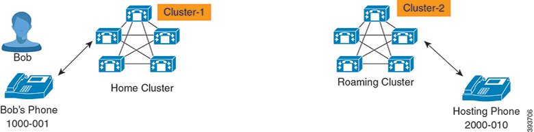
Page 497
Superuser information must be shared across all the clusters irrespective of the cluster in which the user
is logging-in.
Note
Login Process
Cisco Unified Communications Manager supports the Extension Mobility login for a superuser created across
multiple clusters. Extension Mobility login, in the roaming cluster allows superuser to access their phone
settings, such as line appearances, services, dial plans. A superuser can make or receive calls from the roaming
cluster, in the same way as they do in the home cluster.
Figure 8: Call Flow When a User Is in Home Cluster
In the preceding figure, let us assume Bob's DN as 1000-001, Alice's DN as 2000-001 and Kally's DN as
3000-001 registered with Cluster 1, 2 and 3 respectively. When Kally dials Bob's DN 1000-001, Cluster 3
routes the call to Cluster 1 and Bob and Kally are connected.
Feature Configuration Guide for Cisco Unified Communications Manager, Release 15 and SUs
455
Receiving Calls
Extension Mobility Roaming Across Clusters Login

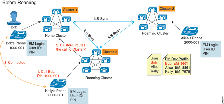
Page 498
Figure 9: Call Flow When User Is in Roaming Cluster
Let us assume Bob's home cluster is down and Bob is configured as superuser who can roam across the
clusters. When Bob moves to Cluster 2 and does Extension Mobility Login, hosting phone gets re-registered
with Bob's settings. Once the login is successful, all other clusters are updated with Bob's new location. Now
when Kally dials Bob's DN 1000-01, Cluster 3 routes the call to Cluster 2 and Bob and Kally are connected.
Similarly, Bob can call Kally by dialing DN 3000-001.
• If a superuser did the Extension Mobility login to another cluster, user will automatically log out from
the home cluster. If the cluster is down, it waits until the cluster is up to log out from the user's previous
login.
• Extension Mobility Roaming Across Clusters supports the multi login behavior. Hence, superuser can
login from multiple devices within the same cluster but not across the clusters.
Note
Feature Configuration Guide for Cisco Unified Communications Manager, Release 15 and SUs
456
Receiving Calls
Extension Mobility Roaming Across Clusters Login
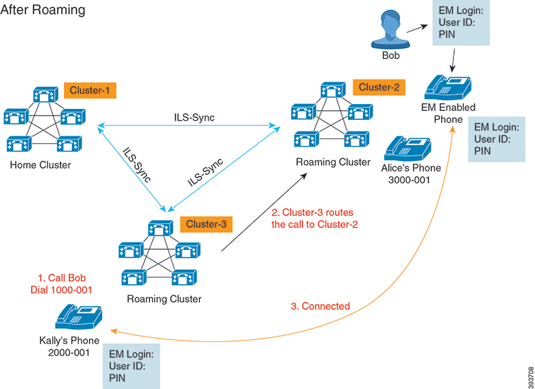

Page 499
ILS Interaction
In Cisco Unified CM Administration, you can configure ILS on a pair of clusters and then join those clusters
to form an ILS network. Once you have established the ILS network, you can join additional clusters to the
network without having to configure the connections between each cluster.
Whenever Extension Mobility login or logout occurs, ILS sync starts to update the available information to
other clusters.
Configuring user as superuser automatically initiates the ILS sync irrespective of Directory Number
configuration for ILS.
Note
For more information, see the Configure Intercluster Lookup Service chapter in the System Configuration
Guide for Cisco Unified Communications Manager at https://www.cisco.com/c/en/us/support/
unified-communications/unified-communications-manager-callmanager/
products-installation-and-configuration-guides-list.html.
Extension Mobility Roaming Across Clusters Task Flow
Procedure
Purpose
Command or Action
Generate a report to identify devices that
support the Extension Mobility feature.
Generate a Phone Feature List, on page 5
Step 1
Configure Extension Mobility to allow users to
temporarily access their phone settings, such as
Configure Extension Mobility by completing,
the following subtasks in order:
Step 2
line appearances, services, and speed dials, from
• Activate Extension Mobility Services, on
page 405
other phones when they login from remote
cluster. Perform this task flow on both home
• Configure the Cisco Extension Mobility
Phone Service, on page 406
and remote clusters, so that users will be able
to access settings from either a home or remote
cluster.
• Create an Extension Mobility Device
Profile for Users, on page 407
• Associate a Device Profile to a User, on
page 407
• Subscribe to Extension Mobility, on page
408
Use this procedure to give Extension Mobility
users the ability to roam between different
Configure Roaming for Extension Mobility
Users, on page 461
Step 3
clusters in an ILS network, while using the same
login credentials.
Feature Configuration Guide for Cisco Unified Communications Manager, Release 15 and SUs
457
Receiving Calls
ILS Interaction

Page 500
Generate a Phone Feature List
Generate a phone feature list report to determine which devices support the feature that you want to configure.
Procedure
Step 1
From Cisco Unified Reporting, choose System Reports.
Step 2
From the list of reports, click Unified CM Phone Feature List.
Step 3
Perform one of the following steps:
• Choose Generate New Report (the bar chart icon) to generate a new report.
• Choose Unified CM Phone Feature List if a report exists.
Step 4
From the Product drop-down list, choose All.
Step 5
Click the name of the feature that you want to configure.
Step 6
Click Submit, to generate the report.
Activate Extension Mobility Services
Procedure
Step 1
From Cisco Unified Serviceability, choose Tools > Service Activation.
Step 2
From the Server drop-down list, choose the requried node.
Step 3
Activate the following services:
a)
Cisco CallManager
b) Cisco Tftp
c)
Cisco Extension Mobility
d) ILS Service
Note
You must choose publisher node to activate the ILS services.
Step 4
Click Save.
Step 5
Click OK.
Configure the Cisco Extension Mobility Phone Service
Configure the extension mobility IP phone service to which users can later subscribe to access extension
mobility.
Feature Configuration Guide for Cisco Unified Communications Manager, Release 15 and SUs
458
Receiving Calls
Generate a Phone Feature List
Page 501
Procedure
Step 1
From Cisco Unified CM Administration, choose Device > Device Settings > Phone Services.
Step 2
Click Add New.
Step 3
In the Service Name field, enter a name for the service.
Step 4
In the Service URL field, enter the Service URL.
The format is http://<IP Address>:8080/emapp/EMAppServlet?device=#DEVICENAME#.
IP Address is the IP address of the Unified Communications Manager where Cisco Extension Mobility
is activated and running.
It should be a IPv4 address.
Example:
http://123.45.67.89:8080/emapp/EMAppServlet?device=#DEVICENAME#
Example:
http://[2001:0001:0001:0067:0000:0000:0000:0134]:8080/emapp/EMAppServlet?device=#DEVICENAME#
This format allows a user to sign-in using User ID and PIN. You can configure more sign-in options for IP
phone users who have subscribed to the extension mobility service. To configure more sign-in options, append
the loginType parameter to the Service URL, in the following formats:
• loginType=DN enables users to sign in using Primary Extension and PIN.
The Service URL format is:http://<IP
Address>:8080/emapp/EMAppServlet?device=#DEVICENAME#&loginType=DN.
• loginType=SP enables users to sign in using Self Service User ID and PIN.
The Service URL format is:http://<IP
Address>:8080/emapp/EMAppServlet?device=#DEVICENAME#&loginType=SP.
• loginType=UID enables users to sign in using User ID and PIN.
The Service URL format is:http://<IP
Address>:8080/emapp/EMAppServlet?device=#DEVICENAME#&loginType=UID.
If you do not append loginType to the end of the URL, the default sign-in option displayed is User ID and
PIN.
Step 5
In the Service Type field, choose whether the service is provisioned to the Services, Directories, or Messages
button.
Step 6
Click Save.
Create an Extension Mobility Device Profile for Users
Configure an extension mobility device profile. This profile acts as a virtual device that maps onto a physical
device when a user logs in to extension mobility. The physical device takes on the characteristics in this
profile.
Feature Configuration Guide for Cisco Unified Communications Manager, Release 15 and SUs
459
Receiving Calls
Create an Extension Mobility Device Profile for Users
Page 502
Procedure
Step 1
From Cisco Unified CM Administration, choose Device > Device Settings > Device Profile.
Step 2
Perform one of the following tasks:
• Click Find to modify the settings and choose an existing device profile from the resulting list.
• Click Add New to add a new device profile and choose an option from the Device Profile Type. Click
Next.
• Choose a device protocol from the Device Protocol drop-down list and click Next.
Step 3
Configure the fields. For more information on the fields and their configuration options, see Online Help.
Step 4
Click Save.
Step 5
From the Association Information section, click Add a new DN.
Step 6
In the Directory Number field, enter the directory number and click Save.
Step 7
Click Reset and follow the prompts.
Associate a Device Profile to a User
Associate a device profile to users so that they can access their settings from a different phone. You associate
a user device profile to a user in the same way that you associate a physical device.
You can use the Bulk Administration Tool (BAT) to add and delete several user device profiles for Cisco
Extension Mobility at one time. See the Bulk Administration Guide for Cisco Unified Communications
Manager.
Tip
Procedure
Step 1
From Cisco Unified CM Administration, choose User Management > End User.
Step 2
Perform one of the following tasks:
• Click Find to modify the settings for an existing user, enter search criteria, and choosing an existing user
from the resulting list.
• Click Add New to add a new user.
Step 3
Under Extension Mobility, locate the device profile that you created and move it from Available Profiles
to Controlled Profiles.
Step 4
Check the Home Cluster check box.
Step 5
Click Save.
Feature Configuration Guide for Cisco Unified Communications Manager, Release 15 and SUs
460
Receiving Calls
Associate a Device Profile to a User

Page 503
Subscribe to Extension Mobility
Subscribe IP phones and device profiles to the extension mobility service so that users can log in, use, and
log out of extension mobility.
Procedure
Step 1
Perform one of the following tasks from Cisco Unified CM Administration:
• Choose Device > Phone, specify search criteria, click Find, and choose a phone which users will use
for extension mobility.
• Choose Device > Device Settings > Device Profile, specify search criteria, click Find, and choose the
device profile that you created.
Step 2
From the Related Links drop-down list, choose Subscribe/Unsubscribe Services, and then click Go.
Step 3
From the Select a Service drop-down list, choose the Extension Mobility service.
Step 4
Click Next.
Step 5
Click Subscribe.
Step 6
Click Save and close the popup window.
Configure Roaming for Extension Mobility Users
Use this procedure to give Extension Mobility users the ability to roam between different clusters in an ILS
network, while using the same login credentials. To do this, you must assign the selected users to the Standard
EM Roaming Across Clusters Super Users access control group.
Before you begin
An ILS network must have been set up as ILS is used to replicate user and login information across the clusters.
Procedure
Step 1
From Cisco Unified CM Administration, choose User Management > User Settings > Access Control
Group.
Step 2
Click Find and select the Standard EM Roaming Across Clusters Super Users group.
Step 3
Click Add End Users to Group button. The Find and List Users pop-up window appears.
Step 4
Click Find and select all the users to whom you want to provide roaming ability.
Step 5
Click Add Selected.
Feature Configuration Guide for Cisco Unified Communications Manager, Release 15 and SUs
461
Receiving Calls
Subscribe to Extension Mobility
Page 504
Extension Mobility Roaming Across Clusters Interactions and
Restrictions
Extension Mobility Roaming Across Clusters Interactions
This section lists the interactions of the Extension Mobility Roaming across Cluster with other Cisco Unified
Communications Manager Administration components.
• Extension Mobility
• Inter-Cluster Lookup Service (ILS)
Extension Mobility Roaming Across Clusters Restrictions
This section lists the restrictions of the Extension Mobility Roaming across Cluster with other Cisco Unified
Communications Manager Administration components.
• If the hub ILS is down, the spokes connected to it will not synchronize until the hub is back.
Different Types of Extension Mobility
The following table lists the different types of Extension Mobility features available in Cisco Unified
Communications Manager and their differences.
Table 45: Differences Between EM, EMCC, and Extension Mobility Roaming Across Cluster
Extension Mobility
Roaming Across Cluster
Extension Mobility Cross
Cluster (EMCC)
Extension Mobility (EM)
Allows user to roam
across other clusters using
own login credentials.
Allows users to access
their phone settings from
a phone in another cluster.
Allows users to
temporarily access their
phone settings from other
phones in the same
cluster.
Description
The roaming cluster
phone registers in the
roaming cluster only.
The remote cluster phone
registers to the user’s
home cluster, accessing
the settings in the home
cluster.
N/A
When the user logs in to
a phone in another cluster
Multiple clusters
Multiple clusters
Single cluster only
Intercluster
Extension Mobility
Roaming must be
configured in all the
cluster.
EMCC must be
configured in the home
cluster and each cluster
that the user visit.
Single cluster only
Configuration
Feature Configuration Guide for Cisco Unified Communications Manager, Release 15 and SUs
462
Receiving Calls
Extension Mobility Roaming Across Clusters Interactions and Restrictions
Page 505
Extension Mobility
Roaming Across Cluster
Extension Mobility Cross
Cluster (EMCC)
Extension Mobility (EM)
Superuser information
maintained in all the
cluster.
Must be maintained in all
clusters.
Single cluster only
User Information
Extension Mobility Roaming Across Clusters Troubleshooting
This section provides information about error codes for EMApp and EMService.
Authentication Error
Problem “Error 201 Authentication Error” appears on the phone.
Solution The user should check that the correct user ID and PIN were entered; the user should check with the
system administrator that the user ID and PIN are correct.
Blank User ID or PIN
Problem “Error 202 Blank User ID or PIN” appears on the phone.
Solution Enter a valid user ID and PIN.
Busy Please Try Again
Problem “Error 26 Busy Please Try Again” appears on the phone.
Solution Check whether the number of concurrent login and logout requests is greater than the Maximum
Concurrent requests service parameter. If so, lower the number of concurrent requests.
To verify the number of concurrent login and logout requests, use the Cisco Unified Real-Time Monitoring
Tool to view the Requests In Progress counter in the Extension Mobility object. For more information, see
the Cisco Unified Real-Time Monitoring Tool Administration Guide at http://www.cisco.com/c/en/us/support/
unified-communications/unified-communications-manager-callmanager/products-maintenance-guides-list.html
Note
Database Error
Problem “Error 6 Database Error” appears on the phone.
Solution Check whether a large number of requests exists. If a large number of requests exists, the Requests
In Progress counter in the Extension Mobility object counter shows a high value. If the requests are rejected
because of a large number of concurrent requests, the Requests Throttled counter also shows a high value.
Collect detailed database logs.
Feature Configuration Guide for Cisco Unified Communications Manager, Release 15 and SUs
463
Receiving Calls
Extension Mobility Roaming Across Clusters Troubleshooting

Page 506
Dev Logon Disabled
Problem “Error 22 Dev Logon Disabled” appears on the phone.
Solution Verify that you checked the Enable Extension Mobility check box in the Phone Configuration
window (Device > Phone).
Device Name Empty
Problem “Error 207 Device Name Empty” appears on the phone.
Solution Check that the URL that is configured for Cisco Extension Mobility is correct. See the Related Topics
section for more information.
Related Topics
Configure the Cisco Extension Mobility Phone Service, on page 406
EM Service Connection Error
Problem “Error 207 EM Service Connection Error” appears on the phone.
Solution Verify that the Cisco Extension Mobility service is running by selecting Tools > Control
Center—Feature in Cisco Unified Serviceability.
Host Not Found
Problem The “Host Not Found” error message appears on the phone.
Solution Check that the Cisco Tomcat service is running by selecting Tools > Control Center—Network
Services in CIsco Unified Serviceability.
HTTP Error
Problem HTTP Error (503) appears on the phone.
Solution
• If you get this error when you press the Services button, check that the Cisco IP Phone Services service
is running by selecting Tools > Control Center—Network Services in Cisco Unified Serviceability.
• If you get this error when you select Extension Mobility service, check that the Cisco Extension Mobility
Application service is running by selecting Tools > Control Center—Network Services in Cisco Unified
Serviceability.
Phone Resets
Problem After users log in or log out, their phones reset instead of restarting.
Possible Cause Locale change is the probable cause of the reset.
Solution No action is required. If the user locale that is associated with the logged-in user or profile is not the
same as the locale or device, after a successful login the phone will restart and then reset. This pattern occurs
because the phone configuration file is rebuilt.
Feature Configuration Guide for Cisco Unified Communications Manager, Release 15 and SUs
464
Receiving Calls
Dev Logon Disabled
Page 507
Phone Services Unavailable After Login
Problem After logging in, the user finds that the phone services are not available.
Possible Cause This problem occurs because the user profile had no services associated with it when it
was loaded on the phone.
Solution
• Ensure that the user profile includes the Cisco Extension Mobility service.
• Change the configuration of the phone where the user is logged in to include Cisco Extension Mobility.
After the phone is updated, the user can access the phone services.
Phone Services Unavailable After Logout
Problem After a user logs out and the phone reverts to the default device profile, the phone services are no
longer available.
Solution Subscribe the phone to the Cisco Extension Mobility service.
User Logged in Elsewhere
Problem “Error 25 User Logged in Elsewhere” appears on the phone.
Solution Check whether the user is logged in to another phone. If multiple logins must be allowed, ensure that
the Multiple Login Behavior service parameter is set to Multiple Logins Allowed.
User Profile Absent
Problem “Error 205 User Profile Absent” appears on the phone.
Solution Associate a device profile to the user.
Feature Configuration Guide for Cisco Unified Communications Manager, Release 15 and SUs
465
Receiving Calls
Phone Services Unavailable After Login
Page 508
Feature Configuration Guide for Cisco Unified Communications Manager, Release 15 and SUs
466
Receiving Calls
User Profile Absent
Page 509
C H A P T E R 35
Hold Reversion
• Hold Reversion Overview, on page 467
• Hold Reversion Prerequisites, on page 467
• Hold Reversion Configuration Task Flow, on page 468
• Hold Reversion Interactions, on page 471
• Hold Reversion Restrictions, on page 472
Hold Reversion Overview
When you place a call on hold, the Hold Reversion feature alerts you when the held call exceeds a configured
time limit. When the configured time limit expires, an alert is generated on your phone to remind you to handle
the call.
The following alerts are available:
• The Phone rings or beeps once
• The status line displays “Hold Reversion”
• The LED next to the line button flashes continuously
• A vibrating handset icon displays
The type of alert that you receive depends on the capabilities of your phone.
Note
To retrieve a reverted call, you can:
• Pick up the handset
• Press the speaker button on the phone
• Press the headset button
• Select the line that is associated with the reverted call
• Press the Resume softkey
For details, see the user guide for your particular phone model.
Hold Reversion Prerequisites
• Cisco CallManager service must be running on at least one node in the cluster
Feature Configuration Guide for Cisco Unified Communications Manager, Release 15 and SUs
467


Page 510
• Cisco CTIManager service must be running on at least one node in the cluster
• Cisco Database Layer Monitor service must be running on the same node as the Cisco CallManager
service
• Cisco RIS Data Collector service must be running on the same node as the Cisco CallManager service
• Cisco Tftp service must be running on at least one node in the cluster
• Cisco Unified Communications Manager Locale Installer must be installed, if you want to use non-English
phone locales or country-specific tones
Hold Reversion Configuration Task Flow
Perform the following steps to configure Hold Reversion for your phones. This procedure assumes that you
have configured directory numbers for phones, or that you are using auto-registration.
Before you begin
• If phone users want the hold reversion messages to display in a language other than English, or if you
want the user to receive country-specific tones for calls, verify that you have installed the locale installer.
• Review Hold Reversion Prerequisites, on page 467
Procedure
Purpose
Command or Action
Run a phone feature list report to determine
which phones support the Hold Reversion
feature.
Generate a Phone Feature List, on page 5
Step 1
Configure the call focus priority setting against
the device pool for your phones.
Configure Call Focus Priority for Hold
Reversion, on page 468
Step 2
Configure the Hold Reversion timer settings.
You can configure the timer using a clusterwide
Perform one of the following procedures:
Step 3
• Configure Hold Reversion Timer Defaults
for Cluster, on page 469
service parameter, or configure the settings on
an individual phone line.
• Configure Hold Reversion Timer Settings
for Phone, on page 470
Note
The settings on an individual phone line
override the clusterwide service parameter
settings.
Configure Call Focus Priority for Hold Reversion
As an administrator, you can prioritize incoming calls and reverted calls. By default, all incoming calls are
handled before reverted calls, however you can change the call focus priority so that reverted calls take
precedence.
Feature Configuration Guide for Cisco Unified Communications Manager, Release 15 and SUs
468
Receiving Calls
Hold Reversion Configuration Task Flow
Page 511
Before you begin
Generate a Phone Feature List, on page 5
Procedure
Step 1
From Cisco Unified CM Administration, choose System > Device Pool and open the device pool that applies
to your phones.
Step 2
In the Reverted Call Focus Priority field, choose one of the following options and click Save:
• Default—Incoming calls have priority over reverted calls.
• Highest—Reverted calls have priority over incoming calls.
Step 3
Click Save.
Step 4
Reset any devices in the Device Pool by performing the following steps:
a)
Click Reset. The Device Reset window displays.
b) In the Device Reset window, click Reset.
What to do next
Perform one of the following procedures to configure Hold Reversion Timer Settings:
• Configure Hold Reversion Timer Defaults for Cluster, on page 469
• Configure Hold Reversion Timer Settings for Phone, on page 470
Configure Hold Reversion Timer Defaults for Cluster
Perform this procedure to configure clusterwide service parameters that apply hold reversion timer default
settings for all phones in the cluster.
When you configure the clusterwide service parameters, the configuration is applied as the default hold
reversion setting for all phones in the cluster. However, the settings on an individual phone line can override
the clusterwide defaults.
Note
Before you begin
Configure Call Focus Priority for Hold Reversion, on page 468
Procedure
Step 1
From Cisco Unified CM Administration, choose System > Service Parameters.
Step 2
From the Server drop-down list, choose the server that is running the CallManager service.
Feature Configuration Guide for Cisco Unified Communications Manager, Release 15 and SUs
469
Receiving Calls
Configure Hold Reversion Timer Defaults for Cluster

Page 512
Step 3
From the Service drop-down list, choose Cisco CallManager.
Step 4
Configure values for the following clusterwide service parameters:
• Hold Reversion Duration—Enter a number from 0 to 1200 (inclusive) to specify the wait time in seconds
before Cisco Unified Communications Manager issues a reverted call alert to the holding party phone.
If you enter 0, Cisco Unified Communications Manager does not issue reverted call alerts, unless it is
configured on a phone line.
• Hold Reversion Interval Notification—Enter a number from 0 to 1200 (inclusive) to specify the wait
time in seconds before Cisco Unified Communications Manager sends periodic reminder alerts to the
holding party phone. If you enter 0, Cisco Unified Communications Manager does not send periodic
reminder alerts unless the timer is configured on a phone line.
Step 5
Click Save.
Configure Hold Reversion Timer Settings for Phone
Perform this procedure to configure Hold Reversion timer settings for a phone and phone line.
You can also configure Hold Reversion timer settings using a clusterwide service parameter. However, the
settings on an individual phone line override the clusterwide service parameter setting.
Note
Before you begin
Perform Configure Hold Reversion Timer Defaults for Cluster, on page 469 to configure Hold Reversion
clusterwide defaults.
Procedure
Step 1
In Cisco Unified CM Administration, choose Device > Phone.
Step 2
Click Find and select the phone on which you want to configure Hold Reversion.
Step 3
In the Association pane on the left, click the phone line on which you want to configure Hold Reversion.
Step 4
Configure values for the following fields:
• Hold Reversion Ring Duration—Enter a number from 0 to 1200 (inclusive) to specify the wait time
in seconds before Cisco Unified Communications Manager issues a reverted call alert. If you enter 0,
Cisco Unified Communications Manager does not issue reverted call alerts to this DN. If you leave the
field empty (the default setting), Cisco Unified Communications Manager applies the setting from the
Hold Reversion Duration service parameter.
• Hold Reversion Ring Interval Notification—Enter a number from 0 to 1200 (inclusive) to specify the
wait time in seconds before Cisco Unified Communications Manager sends periodic reminder alerts. If
you enter 0, Cisco Unified Communications Manager does not send periodic reminder alerts to this DN.
If you leave the field empty (the default setting), Cisco Unified Communications Manager applies the
setting from the Hold Reversion Interval Notification service parameter.
Step 5
Click Save.
Feature Configuration Guide for Cisco Unified Communications Manager, Release 15 and SUs
470
Receiving Calls
Configure Hold Reversion Timer Settings for Phone

Page 513
Step 6
Reset the phone by performing the following steps:
a)
Click Reset. The Reset Device window displays.
b) Click Reset.
Hold Reversion Interactions
Table 46: Hold Reversion Feature Interactions
Interactions
Feature
MOH is supported on a reverted call if MOH is configured for a normal held call.
Music on Hold
If hold reversion is invoked and the held party presses the Park softkey, the holding
party still receives hold reversion alerts and can retrieve the call. When the holding
party retrieves the call, the holding party receives MOH, if configured.
If the held party parks before the hold duration exceeds the configured time limit, the
system suppresses all hold reversion alerts until the call is picked up or redirected.
Call Park
When a multilevel precedence and preemption (MLPP) call is put on hold and reverts,
the MLPP call loses its preemption status, and the reverted call gets treated as a routine
call.
After the call reverts, the system does not play a preemption ring. If a high precedence
call becomes a reverted call, the system does not play a precedence tone.
MLPP
CTI applications can access hold reversion functionality when the feature is enabled
for a line or the system. Cisco-provided applications such as Cisco Unified
Communications Manager Assistant and attendant console provide hold reversion
functionality using the CTI interface.
When hold reversion gets invoked, the CTI port receives event notification instead of
the audible tone presented on Cisco Unified IP Phones. CTI ports and route points
receive the event notification once only, whereas Cisco Unified IP Phones receive
alerts at regular intervals.
See the following API documents for information about CTI requirements and
interactions with hold reversion:
• Cisco Unified Communications JTAPI Developer Guide
• Cisco Unified Communications TAPI Developer Guide
CTI Applications
SCCP phones support a minimum Hold Reversion Notification Interval (HRNI) of 5
seconds, whereas SIP phones support a minimum of 10 seconds. SCCP phones set
for the minimum HRNI of 5 seconds may experience a Hold Reversion Notification
ring delay of 10 seconds when handling calls involving SIP phones.
Hold Reversion
Interval for SCCP
phones when
interacting with SIP
Phones
Feature Configuration Guide for Cisco Unified Communications Manager, Release 15 and SUs
471
Receiving Calls
Hold Reversion Interactions
Page 514
Interactions
Feature
If a Cisco Unified IP Phone that supports hold reversion shares a line with a phone
device that does not support hold reversion, the hold reversion configuration settings
display only for the line on the supporting device.
If a shared line device disables the feature, hold reversion gets disabled on all other
devices that share the line.
Shared Lines
If the ring settings that are configured for the phone specify Disabled, the phone does
not ring, flash, or beep for the hold reversion feature.
Ring Settings
Hold Reversion Restrictions
Restriction
Feature
Cisco Extension Mobility and Cisco Web Dialer features do not support the hold
reversion feature.
Cisco Extension Mobility
and Cisco Web Dialer
This feature does not support SCCP analog phone types, such as ATA 186,
DPA-7610, and DPA-7630.
Only certain on-net phone devices that are running SCCP on a node can invoke
the hold reversion feature.
SCCP phones
If a directory number is associated to a phone that does not support hold reversion,
the feature settings do not display for that directory number in the Directory
Number Configuration window.
Directory numbers
If a Cisco Unified IP Phone that supports hold reversion shares a line with a
phone device that does not support hold reversion, the hold reversion configuration
settings display only for the line on the supporting device.
If a shared-line device disables this feature, hold reversion gets disabled on all
other devices that share this line.
Shared lines
Hold reversion ring uses the ring settings that Cisco Unified Communications
Manager Administration defines for that user (disable, flash only, ring once, ring,
beep only) except that flash gets converted to flash once, and ring gets converted
to ring once.
Note
When an IP Phone call is on normal hold, the ring settings (Phone Idle) from
the Call Manager is applied.
Ring settings
The maximum number of reverted calls on a line equals the maximum number
of calls on your system.
Maximum number of
reverted calls
Feature Configuration Guide for Cisco Unified Communications Manager, Release 15 and SUs
472
Receiving Calls
Hold Reversion Restrictions
Page 515
Restriction
Feature
To enable this feature with CTI applications, ensure that the CTI application is
certified to work with this feature and this release. Otherwise, the CTI application
may fail because the hold reversion feature may affect existing CTI applications.
This feature gets disabled by default. See the following API documents for
information about CTI requirements:
• Cisco Unified TAPI Developers Guide for Cisco Unified Communications
Manager
• Cisco Unified JTAPI Developers Guide for Cisco Unified Communications
Manager
CTI Applications
You cannot configure hold reversion settings for DNs that are associated with
phones that do not support this feature. Only Cisco Unified IP Phones that support
the hold reversion feature display the hold reversion timer settings in the Directory
Number Configuration window.
When Hold Reversion is configured for the system, the phone must support the
feature or the feature does not activate.
See Cisco Unified IP Phone administration guides for Cisco Unified IP Phone
models that support hold reversion and this version of Unified Communications
Manager for any phone restrictions with hold reversion.
Cisco Unified IP Phones
Feature Configuration Guide for Cisco Unified Communications Manager, Release 15 and SUs
473
Receiving Calls
Hold Reversion Restrictions
Page 516
Feature Configuration Guide for Cisco Unified Communications Manager, Release 15 and SUs
474
Receiving Calls
Hold Reversion Restrictions
Page 517
C H A P T E R 36
Accessing Hunt Groups
• Hunt Group Overview, on page 475
• Hunt Group Prerequisites, on page 476
• Hunt Group Configuration Task Flow, on page 476
• Hunt Group Interactions, on page 481
• Hunt Group Restrictions, on page 482
Hunt Group Overview
A Hunt Group is a group of lines that are organized hierarchically, so that if the first number in the hunt group
list is busy, the system dials the second number. If the second number is busy, the system dials the next number,
and so on.
The phone users can log in to or log out of the hunt groups by using the HLog softkey or the Hunt Group line
button on the IP phone. The phone provides a visual status of the login state, so that the user can determine
whether they are logged in to one or more of their line groups.
The Hunt Group feature provides the following functions:
• The HLog softkey on the IP phone allows the user to toggle between login and logout of phone.
• A hunt group allows a caller to automatically find an available line from amongst a group of extensions.
• The Hunt Group Log Off feature allows phone users to prevent their phones from receiving incoming
calls that get routed to directory numbers. Regardless of the phone status, the phone rings normally for
incoming calls that are not calls to one or more line groups associated with the phone.
The directory numbers (DNs) belong to line groups that are associated with the
phone.
Note
• System administrators can log in or log out the users from the phones that are automatically logged into
hunt groups.
• The HLog softkey allows a phone user to log a phone out of all line groups to which the phone directory
numbers belong.
Feature Configuration Guide for Cisco Unified Communications Manager, Release 15 and SUs
475


Page 518
• From Cisco Unified Communications Manager Release 9.0 onward, the Hunt Group Log Off feature
enables the use of mobile device as a desk phone. When you use the Hlog softkey through your mobile
client, you no longer receive calls that are placed to the hunt pilot.
Hunt Group Prerequisites
• The phones must be running Skinny Client Control Protocol (SCCP) or Session Initiation Protocol (SIP).
• The phone ringtone file must be located in the TFTP directory (/usr/local/cm/tftp).
Hunt Group Configuration Task Flow
Before you begin
• Review Hunt Group Prerequisites, on page 476
Procedure
Purpose
Command or Action
Configure a softkey template for the HLog
softkey.
Configure a Softkey Template for Hunt Group,
on page 477
Step 1
Optional. To make the softkey template
available to phones, you must complete either
To Associate a Softkey Template with a
Common Device Configuration, on page 478,
complete the following subtasks:
Step 2
this step or the following step. Follow this step
if your system uses a Common Device
• Add a Softkey Template to a Common
Device Configuration, on page 478
Configuration to apply configuration options to
phones. This is the most commonly used
• Associate a Common Device
Configuration with a Phone, on page 479 method for making a softkey template available
to phones.
Optional. Use this procedure either as an
alternative to associating the softkey template
Associate a Softkey Template with a Phone, on
page 479
Step 3
with the Common Device Configuration, or in
conjunction with the Common Device
Configuration. Use this procedure in
conjunction with the Common Device
Configuration if you need to assign a softkey
template that overrides the assignment in the
Common Device Configuration or any other
default softkey assignment.
Configure phones to automatically log in to or
log out of hunt groups and hunt lists.
Configure Phones for Hunt Group, on page 480
Step 4
Feature Configuration Guide for Cisco Unified Communications Manager, Release 15 and SUs
476
Receiving Calls
Hunt Group Prerequisites
Page 519
Configure a Softkey Template for Hunt Group
The HLog softkey appears on the phone when the phone is in the following call states:
• Connected
• On Hook
• Off Hook
You must create a new softkey template to configure the HLog softkey. You cannot configure the HLog
softkey in a standard softkey template.
Note
Use this procedure to make the HLog softkey available:
Procedure
Step 1
From Cisco Unified CM Administration, choose Device > Device Settings > Softkey Template.
Step 2
Perform the following steps to create a new softkey template; otherwise, proceed to the next step.
a)
Click Add New.
b) Select a default template and click Copy.
c)
Enter a new name for the template in the Softkey Template Name field.
d) Click Save.
Step 3
Perform the following steps to add softkeys to an existing template.
a)
Click Find and enter the search criteria.
b) Select the required existing template.
Step 4
Check the Default Softkey Template check box to designate this softkey template as the default softkey
template.
Note
If you designate a softkey template as the default softkey template, you cannot delete it unless you first remove
the default designation.
Step 5
Choose Configure Softkey Layout from the Related Links drop-down list in the upper right corner and
click Go.
Step 6
From the Select a Call State to Configure drop-down list, choose the call state for which you want the softkey
to display.
Step 7
From the Unselected Softkeys list, choose the softkey to add and click the right arrow to move the softkey
to the Selected Softkeys list. Use the up and down arrows to change the position of the new softkey.
Step 8
Repeat the previous step to display the softkey in additional call states.
Step 9
Click Save.
Step 10
Perform one of the following tasks:
• Click Apply Config if you modified a template that is already associated with devices to restart the
devices.
Feature Configuration Guide for Cisco Unified Communications Manager, Release 15 and SUs
477
Receiving Calls
Configure a Softkey Template for Hunt Group

Page 520
• If you created a new softkey template, associate the template with the devices and then restart them. For
more information, see Add a Softkey Template to a Common Device Configuration and Associate a
Softkey Template with a Phone sections.
What to do next
Perform one of the following procedures:
• Add a Softkey Template to a Common Device Configuration, on page 478
• Associate a Softkey Template with a Phone, on page 479
Associate a Softkey Template with a Common Device Configuration
Optional. There are two ways to associate a softkey template with a phone:
• Add the softkey template to the Phone Configuration.
• Add the softkey template to the Common Device Configuration.
The procedures in this section describe how to associate the softkey template with a Common Device
Configuration. Follow these procedures if your system uses a Common Device Configuration to apply
configuration options to phones. This is the most commonly used method for making a softkey template
available to phones.
To use the alternative method, see Associate a Softkey Template with a Phone, on page 479.
Before you begin
Configure a Softkey Template for Hunt Group, on page 477
Procedure
Purpose
Command or Action
Add a Softkey Template to a Common Device
Configuration, on page 478
Step 1
Associate a Common Device Configuration
with a Phone, on page 479
Step 2
Add a Softkey Template to a Common Device Configuration
Procedure
Step 1
From Cisco Unified CM Administration, choose Device > Device Settings > Common Device Configuration.
Step 2
Perform the following steps to create a new Common Device Configuration and associate the softkey template
with it; otherwise, proceed to the next step.
Feature Configuration Guide for Cisco Unified Communications Manager, Release 15 and SUs
478
Receiving Calls
Associate a Softkey Template with a Common Device Configuration
Page 521
a)
Click Add New.
b) Enter a name for the Common Device Configuration in the Name field.
c)
Click Save.
Step 3
Perform the following steps to add the softkey template to an existing Common Device Configuration.
a)
Click Find and enter the search criteria.
b) Click an existing Common Device Configuration.
Step 4
In the Softkey Template drop-down list, choose the softkey template that contains the softkey that you want
to make available.
Step 5
Click Save.
Step 6
Perform one of the following tasks:
• If you modified a Common Device Configuration that is already associated with devices, click Apply
Config to restart the devices.
• If you created a new Common Device Configuration, associate the configuration with devices and then
restart them.
Associate a Common Device Configuration with a Phone
Before you begin
Add a Softkey Template to a Common Device Configuration, on page 478
Procedure
Step 1
From Cisco Unified CM Administration, choose Device > Phone.
Step 2
Click Find and select the phone device to add the softkey template.
Step 3
From the Common Device Configuration drop-down list, choose the common device configuration that
contains the new softkey template.
Step 4
Click Save.
Step 5
Click Reset to update the phone settings.
Associate a Softkey Template with a Phone
This procedure is optional. You can use this procedure as an alternative to associating the softkey template
with the Common Device Configuration. This procedure also works in conjunction with the Common Device
Configuration: use it when you need to assign a softkey template that overrides the assignment in the Common
Device Configuration or any other default softkey assignment.
Before you begin
Configure a Softkey Template for Hunt Group, on page 477
Feature Configuration Guide for Cisco Unified Communications Manager, Release 15 and SUs
479
Receiving Calls
Associate a Common Device Configuration with a Phone
Page 522
Procedure
Step 1
From Cisco Unified CM Administration, choose Device > Phone.
The Find and List Phones window appears.
Step 2
Choose the phone to which you want to add the softkey template.
The Phone Configuration window appears.
Step 3
From the Softkey Template drop-down list, choose the template that contains the new softkey.
Step 4
Click Save.
A dialog box appears with a message to press Reset to update the phone settings.
Configure Phones for Hunt Group
Use this procedure to configure phones to automatically log in to or log out of hunt groups and hunt lists.
Before you begin
Ensure the phone directory numbers belong to one or more hunt groups.
See the Administration Guide for Cisco Unified Communications Manager for information on hunt groups
and hunt lists.
Procedure
Step 1
From Cisco Unified CM Administration, choose Device > Phone.
Step 2
Perform one of the following tasks:
a)
To modify the fields for an existing phone, enter search criteria and choose a phone from the resulting
list. The Phone Configuration window appears.
b) To add a new phone, click Add New.
The Add a New Phone window appears.
Step 3
In the Phone Configuration window, perform one of the following tasks:
a)
To log out the phone from the hunt group, uncheck the Logged Into Hunt Group check box.
b) To log in the phone to the hunt group, ensure that the Logged Into Hunt Group check box is checked.
Note
The Logged Into Hunt Group check box remains checked by default for all phones.
Step 4
Click Save.
Configure Hunt Group Service Parameter
The Hunt Group Logoff Notification service parameter provides the option to turn audible ringtones on or
off when calls that come in to a line group arrive at a phone that is currently logged out. This ringtone alerts
Feature Configuration Guide for Cisco Unified Communications Manager, Release 15 and SUs
480
Receiving Calls
Configure Phones for Hunt Group
Page 523
a logged-out user that there is an incoming call to a hunt list to which the line is a member, but the call will
not ring at the phone of that line group member because of the logged-out status.
To configure the Hunt Group Logoff Notification service parameter, perform the following steps.
Procedure
Step 1
From Cisco Unified CM Administration, choose System > Service Parameters.
Step 2
From the Server drop-down list, choose the server that is running the Cisco CallManager service.
Step 3
From the Service drop-down list, choose Cisco CallManager.
The Service Parameter Configuration window appears.
Step 4
In the Clusterwide Parameters (Device - Phone) section, configure values for the following Hunt Group
Logoff Notification service parameter:
Enter a name for the ringtone file that Cisco IP Phones play when a member of a line group (hunt group) has
logged out. The default value for this service parameter is None, which indicates no ringtone. You can enter
a maximum of 255 characters.
Step 5
Click Save.
The window refreshes, and Cisco Unified Communications Manager updates the service parameter with your
changes.
Hunt Group Interactions
Interaction
Feature
If a phone is logged out of a line group and an extension on the phone is not
shared, the line group does not ring that directory number (DN) in the line group.
When the line group would normally offer the call to the DN, call processing
skips the DN and acts as if the DN does not belong to the line group.
Non-shared-line Directory
Number
Because the Log Out of Hunt Group feature is device-based, when a user logs a
phone out, the feature affects only the logged-out phone. Calls to a line group
that contains a shared-line directory number behave as follows:
• The DN does not ring if all phones that share that DN are logged out.
• The DN does ring if one or more phones that share the DN are logged in.
• The audible ring on a phone that is logged out is turned off by default. Cisco
Unified Communications Manager provides a system parameter that can be
set, so that a different ring tone plays when a call comes in to a logged-out
hunt group member.
Shared-line Directory
Number
Feature Configuration Guide for Cisco Unified Communications Manager, Release 15 and SUs
481
Receiving Calls
Hunt Group Interactions
Page 524
Hunt Group Restrictions
Description
Restriction
When the user enables the Hunt Group Log Off feature by pressing the HLog
softkey, the phone gets logged out from all associated line groups. This is because
Hunt Group Log Off is a device-based feature. If a phone has DNs that belong
to multiple line groups, pressing the HLog softkey logs the phone out of all
associated line groups.
Multiple Line Groups
• When a phone that is running SIP (7906, 7911, 7941, 7961, ) is logged in
to hunt groups and Call Forward All is activated, the call gets presented to
the phone that is running SIP.
• When 7940 and 7960 phones that are running SIP are logged in to hunt
groups and Call Forward All is activated, the phones get skipped and the
next phone in the line group rings.
• 7940 and 7960 phones that are running SIP and third-party phones that are
running SIP can be logged in to or logged out of hunt groups by using the
Phone Configuration window, but no softkey support exists.
• 7940 and 7960 phones that are running SIP and third-party phones that are
running SIP do not show “Logged out of hunt groups” on the status line.
• 7940 and 7960 phones that are running SIP and third-party phones that are
running SIP do not play the Hunt Group Logoff Notification tone regardless
of whether the tone is configured.
7940, 7960, and
third-party SIP phones
Feature Configuration Guide for Cisco Unified Communications Manager, Release 15 and SUs
482
Receiving Calls
Hunt Group Restrictions
Page 525
C H A P T E R 37
Malicious Call Identification
• Malicious Call Identification Overview, on page 483
• Malicious Call Identification Prerequisites, on page 483
• Malicious Call Identification Configuration Task Flow, on page 484
• Malicious Call Identification Interactions, on page 490
• Malicious Call Identification Restrictions, on page 491
• Malicious Call ID Troubleshooting, on page 492
Malicious Call Identification Overview
You can configure the Malicious Call Identification (MCID) feature to track troublesome or threatening calls.
Users can report these calls by requesting that Cisco Unified Communications Manager identify and register
the source of the incoming call in the network.
When the MCID feature is configured, the following actions take place:
1.
The user receives a threatening call and presses Malicious call (or enters the feature code *39 if using a
POTS phone that is connected to an SCCP gateway).
2.
Cisco Unified Communications Manager sends the user a confirmation tone and a text message, if the
phone has a display, to acknowledge receiving the MCID notification.
3.
Cisco Unified Communications Manager updates the call details record (CDR) for the call with an indication
that the call is registered as a malicious call.
4.
Cisco Unified Communications Manager generates the alarm and local syslogs entry that contains the
event information.
5.
Cisco Unified Communications Manager sends an MCID invocation through the facility message to the
connected network. The facility information element (IE) encodes the MCID invocation.
6.
After receiving this notification, the PSTN or other connected network can take actions, such as providing
legal authorities with the call information.
Malicious Call Identification Prerequisites
• Gateways and connections that support MCID:
• PRI gateways that use the MGCP PRI backhaul interface for T1 (NI2) and E1 (ETSI) connections
• H.323 trunks and gateways
Feature Configuration Guide for Cisco Unified Communications Manager, Release 15 and SUs
483

Page 526
• IP Phones that support MCID
Malicious Call Identification Configuration Task Flow
Before you begin
• Review Malicious Call Identification Prerequisites, on page 483
Procedure
Purpose
Command or Action
Generate a report to identify devices that
support the MCID feature.
Generate a Phone Feature List, on page 5
Step 1
Enable Cisco Unified Communications Manager
to flag a call detail record (CDR) with the
MCID indicator.
Set Malicious Call ID Service Parameter, on
page 485
Step 2
Configure alarms to ensure that alarm
information displays in the system logs.
Configure Malicious Call ID Alarms, on page
485
Step 3
Configure a softkey template with MCID.
Configure a Softkey Template for Malicious
Call Identification, on page 486
Step 4
Note
The Cisco Unified IP Phones 8900 and 9900
Series support MCID with feature button only.
Optional. To make the softkey template
available to phones, you must complete either
To Associate a Softkey Template with a
Common Device Configuration, on page 487,
complete the following subtasks:
Step 5
this step or the following step. Follow this step
if your system uses a Common Device
• Add a Softkey Template to a Common
Device Configuration, on page 487
Configuration to apply configuration options
to phones. This is the most commonly used
• Associate a Common Device
Configuration with a Phone, on page 488 method for making a softkey template available
to phones.
Optional. Use this procedure either as an
alternative to associating the softkey template
Associate a Softkey Template with a Phone, on
page 488
Step 6
with the Common Device Configuration, or in
conjunction with the Common Device
Configuration. Use this procedure in
conjunction with the Common Device
Configuration if you need assign a softkey
template that overrides the assignment in the
Common Device Configuration or any other
default softkey assignment.
Perform this step to add and configure the
MCID button to a phone.
To Configure Malicious Call Identification
Button, on page 489, complete the following
subtasks:
Step 7
Feature Configuration Guide for Cisco Unified Communications Manager, Release 15 and SUs
484
Receiving Calls
Malicious Call Identification Configuration Task Flow
Page 527
Purpose
Command or Action
• Configure Malicious Call ID Phone Button
Template, on page 489
• Associate a Button Template with a Phone
, on page 490
Set Malicious Call ID Service Parameter
To enable Unified Communications Manager to flag a CDR with the MCID indicator, you must enable the
CDR flag.
Before you begin
Configure Malicious Call ID Alarms, on page 485
Procedure
Step 1
From Cisco Unified CM Administration, choose System > Service Parameters.
Step 2
From the Server drop-down list, choose the Unified Communications Manager server name.
Step 3
From the Service drop-down list, choose Cisco CallManager.
The Service Parameter Configuration window displays.
Step 4
In the System area, set the CDR Enabled Flag field to True.
Step 5
Click Save.
Configure Malicious Call ID Alarms
In the Local Syslogs, you must set the alarm event level and activate alarms for MCID.
Cisco Business Edition 5000 systems support only one node.
Before you begin
Set Malicious Call ID Service Parameter, on page 485
Procedure
Step 1
From Cisco Unified Serviceability, choose Alarm > Configuration.
The Alarm Configuration window displays.
Step 2
From the Server drop-down list, choose the Unified Communications Manager server and click Go.
Step 3
From the Service Group drop-down list, choose CM Services. The Alarm Configuration window updates
with configuration fields.
Step 4
From the Service drop-down list, choose Cisco CallManager.
Step 5
Under Local Syslogs, in the Alarm Event Level drop-down list, choose Informational.
Feature Configuration Guide for Cisco Unified Communications Manager, Release 15 and SUs
485
Receiving Calls
Set Malicious Call ID Service Parameter
Page 528
The Alarm Configuration window updates with configuration fields.
Step 6
Under Local Syslogs, check the Enable Alarm check box.
Step 7
If you want to enable the alarm for all nodes in the cluster, check the Apply to All Nodes check box.
Step 8
To turn on the informational alarm, click Update.
Configure a Softkey Template for Malicious Call Identification
Skinny Client Control Protocol (SCCP) IP phones use a softkey to invoke the MCID feature.
Note
Before you begin
Configure Malicious Call ID Alarms, on page 485
Procedure
Step 1
From Cisco Unified CM Administration, choose Device > Device Settings > Softkey Template.
Step 2
Perform the following steps to create a new softkey template; otherwise, proceed to the next step.
a)
Click Add New.
b) Select a default template and click Copy.
c)
Enter a new name for the template in the Softkey Template Name field.
d) Click Save.
Step 3
Perform the following steps to add softkeys to an existing template.
a)
Click Find and enter the search criteria.
b) Select the required existing template.
Step 4
Check the Default Softkey Template check box to designate this softkey template as the default softkey
template.
Note
If you designate a softkey template as the default softkey template, you cannot delete it unless you first remove
the default designation.
Step 5
Choose Configure Softkey Layout from the Related Links drop-down list in the upper right corner and
click Go.
Step 6
In the Select a call state to configure field, choose Connected.
The list of Unselected Softkeys changes to display the available softkeys for this call state.
Step 7
In the Unselected Softkeys drop-down list, choose Toggle Malicious Call Trace (MCID).
Step 8
From the Unselected Softkeys list, choose the softkey to add and click the right arrow to move the softkey
to the Selected Softkeys list. Use the up and down arrows to change the position of the new softkey.
Step 9
Click Save.
Feature Configuration Guide for Cisco Unified Communications Manager, Release 15 and SUs
486
Receiving Calls
Configure a Softkey Template for Malicious Call Identification

Page 529
Associate a Softkey Template with a Common Device Configuration
Optional. There are two ways to associate a softkey template with a phone:
• Add the softkey template to the Phone Configuration.
• Add the softkey template to the Common Device Configuration.
The procedures in this section describe how to associate the softkey template with a Common Device
Configuration. Follow these procedures if your system uses a Common Device Configuration to apply
configuration options to phones. This is the most commonly used method for making a softkey template
available to phones.
To use the alternative method, see Associate a Softkey Template with a Phone, on page 488.
Before you begin
Configure a Softkey Template for Malicious Call Identification, on page 486
Procedure
Purpose
Command or Action
Add a Softkey Template to a Common Device
Configuration, on page 487
Step 1
Associate a Common Device Configuration
with a Phone, on page 488
Step 2
Add a Softkey Template to a Common Device Configuration
Before you begin
Configure a Softkey Template for Malicious Call Identification, on page 486
Procedure
Step 1
From Cisco Unified CM Administration, choose Device > Device Settings > Common Device Configuration.
Step 2
Perform the following steps to create a new Common Device Configuration and associate the softkey template
with it; otherwise, proceed to the next step.
a)
Click Add New.
b) Enter a name for the Common Device Configuration in the Name field.
c)
Click Save.
Step 3
Perform the following steps to add the softkey template to an existing Common Device Configuration.
a)
Click Find and enter the search criteria.
b) Click an existing Common Device Configuration.
Step 4
In the Softkey Template drop-down list, choose the softkey template that contains the softkey that you want
to make available.
Feature Configuration Guide for Cisco Unified Communications Manager, Release 15 and SUs
487
Receiving Calls
Associate a Softkey Template with a Common Device Configuration
Page 530
Step 5
Click Save.
Step 6
Perform one of the following tasks:
• If you modified a Common Device Configuration that is already associated with devices, click Apply
Config to restart the devices.
• If you created a new Common Device Configuration, associate the configuration with devices and then
restart them.
Associate a Common Device Configuration with a Phone
Before you begin
Add a Softkey Template to a Common Device Configuration, on page 487
Procedure
Step 1
From Cisco Unified CM Administration, choose Device > Phone.
Step 2
Click Find and select the phone device to add the softkey template.
Step 3
From the Common Device Configuration drop-down list, choose the common device configuration that
contains the new softkey template.
Step 4
Click Save.
Step 5
Click Reset to update the phone settings.
Associate a Softkey Template with a Phone
Optional. Use this procedure as an alternative to associating the softkey template with the Common Device
Configuration. This procedure also works in conjunction with the Common Device Configuration. You can
use it when you need to assign a softkey template that overrides the assignment in the Common Device
Configuration or any other default softkey assignment.
Procedure
Step 1
From Cisco Unified CM Administration, choose Device > Phone.
Step 2
Click Find to select the phone to add the softkey template.
Step 3
From the Softkey Template drop-down list, choose the template that contains the new softkey.
Step 4
Click Save.
Step 5
Press Reset to update the phone settings.
Feature Configuration Guide for Cisco Unified Communications Manager, Release 15 and SUs
488
Receiving Calls
Associate a Common Device Configuration with a Phone
Page 531
Configure Malicious Call Identification Button
The procedures in this section describe how to configure the Malicious Call Identification button.
Before you begin
Configure Malicious Call ID Alarms, on page 485
Procedure
Purpose
Command or Action
Perform this step to assign Malicious Call
Identification button features to line or speed
dial keys.
Configure Malicious Call ID Phone Button
Template, on page 489.
Step 1
Perform this step to configure the Malicious
Call Identification button for a phone.
Associate a Button Template with a Phone , on
page 490
Step 2
Configure Malicious Call ID Phone Button Template
Before you begin
Configure Malicious Call ID Alarms, on page 485
Procedure
Step 1
From Cisco Unified CM Administration, choose Device > Device Settings > Phone Button Template.
Step 2
Click Find to display list of supported phone templates.
Step 3
Perform the following steps if you want to create a new phone button template; otherwise, proceed to the next
step.
a)
Select a default template for the model of phone and click Copy.
b) In the Phone Button Template Information field, enter a new name for the template.
c)
Click Save.
Step 4
Perform the following steps if you want to add phone buttons to an existing template.
a)
Click Find and enter the search criteria.
b) Choose an existing template.
Step 5
From the Line drop-down list, choose feature that you want to add to the template.
Step 6
Click Save.
Step 7
Perform one of the following tasks:
• Click Apply Config if you modified a template that is already associated with devices to restart the
devices.
• If you created a new softkey template, associate the template with the devices and then restart them.
Feature Configuration Guide for Cisco Unified Communications Manager, Release 15 and SUs
489
Receiving Calls
Configure Malicious Call Identification Button
Page 532
Associate a Button Template with a Phone
Before you begin
Configure Malicious Call ID Phone Button Template, on page 489
Procedure
Step 1
From Cisco Unified CM Administration, choose Device > Phone.
Step 2
Click Find to display the list of configured phones.
Step 3
Choose the phone to which you want to add the phone button template.
Step 4
In the Phone Button Template drop-down list, choose the phone button template that contains the new feature
button.
Step 5
Click Save.
A dialog box is displayed with a message to press Reset to update the phone settings.
Malicious Call Identification Interactions
Table 47: Malicious Call Identification Interactions
Interaction
Feature
When a user is connected to a conference, the user can use the MCID feature to
flag the call as a malicious call. Cisco Unified Communications Manager sends
the MCID indication to the user, generates the alarm, and updates the CDR.
However, Cisco Unified Communications Manager does not send an MCID
invoke message to the connected network that might be involved in the conference.
Conference Calls
Extension Mobility users can have the MCID softkey as part of their user device
profile and can use this feature when they are logged on to a phone.
Extension Mobility
To track malicious calls by using CDR, you must set the CDR Enabled Flag to
True in the Cisco CallManager service parameter. When the MCID feature is
used during a call, the CDR for the call contains CallFlag=MALICIOUS in the
Comment field.
Call Detail Records
Feature Configuration Guide for Cisco Unified Communications Manager, Release 15 and SUs
490
Receiving Calls
Associate a Button Template with a Phone
Page 533
Interaction
Feature
To record alarms for the MCID feature in the Local Syslogs, you must configure
alarms in Cisco Unified Serviceability. Under Local Syslogs, enable alarms for
the Informational alarm event level.
When the MCID feature is used during a call, the system logs an SDL trace and
a Cisco Unified Communications Manager trace in alarms. You can view the
Alarm Event Log by using Cisco Unified Serviceability. The traces provide the
following information:
• Date and time
• Type of event: Information
• Information: The Malicious Call Identification feature is invoked in Cisco
Unified Communications Manager
• Called Party Number
• Called Device Name
• Called Display Name
• Calling Party Number
• Calling Device Name
• Calling Display Name
• Application ID
• Cluster ID
• Node ID
For more information about alarms and traces, see the Cisco Unified Serviceability
Administration Guide at http://www.cisco.com/c/en/us/support/
unified-communications/unified-communications-manager-callmanager/
products-maintenance-guides-list.html.
Alarms
The Cisco ATA 186 analog phone ports support MCID by using the feature code
(*39).
Cisco ATA 186 analog
phone ports
Malicious Call Identification Restrictions
Table 48: Malicious Call Identification Restrictions
Restriction
Feature
Cisco Unified Communications Manager supports
only the malicious call identification originating
function (MCID-O). Cisco Unified Communications
Manager does not support the malicious call
identification terminating function (MCID-T). If Cisco
Unified Communications Manager receives a
notification from the network of a malicious call
identification, Cisco Unified Communications
Manager ignores the notification.
Malicious Call Identification Terminating (MCID-T)
function
Feature Configuration Guide for Cisco Unified Communications Manager, Release 15 and SUs
491
Receiving Calls
Malicious Call Identification Restrictions
Page 534
Restriction
Feature
MCID does not work across intercluster trunks
because Cisco Unified Communications Manager
does not support the MCID-T function.
Intercluster trunks
Cisco MGCP FXS gateways do not support MCID.
No mechanism exists for accepting the hookflash and
collecting the feature code in MGCP.
Cisco MGCP FXS gateways
MCID does not work over QSIG trunks because
MCID is not a QSIG standard.
QSIG trunks
Cisco VG248 Analog Phone Gateway does not
support MCID.
Cisco VG248 Analog Phone Gateway
MCID does not support SIP trunks.
SIP trunks
System does not support using MCID and Immediate
Divert features together.
Immediate Divert
Malicious Call ID Troubleshooting
To track and troubleshoot Malicious Call ID, you can use Cisco Unified Communications Manager SDL
traces and alarms. For information about setting traps and traces for MCID, see the Cisco Unified Serviceability
Administration Guide. For information about how to generate reports for MCID, see the Cisco Unified CDR
Analysis and Reporting Administration Guide.
Feature Configuration Guide for Cisco Unified Communications Manager, Release 15 and SUs
492
Receiving Calls
Malicious Call ID Troubleshooting
Page 535
C H A P T E R 38
Call Transfer
• Call Transfer Overview, on page 493
• Call Transfer Configuration Task Flow, on page 494
• Call Transfer Interactions, on page 504
• Call Transfer Restrictions, on page 505
Call Transfer Overview
The transfer feature allows you to redirect a connected call from your phone to another number. After call
transfer, your call is disconnected and the transferred call is established as a new call connection.
Following are the different types of call transfers:
• Consult Transfer and Blind Transfer—In Consult Transfer, a transferring phone user can redirect the
caller to a different target address, after consulting with the target phone user that answers the call. That
is, the transferring phone user will stay on the call until the target phone user answers the call. In Blind
Transfer, the transferring phone user connects the caller to a destination line before the target of the
transfer answers the call.
Most phones use hard keys or softkeys for Transfer. Both Consult Transfer and Blind Transfer do not
require separate configuration. The difference between the two types of transfer depends on when the
transferring party presses the Transfer button a second time. For a consult transfer, the transferring party
presses the Transfer button after the target answers, while for a Blind Transfer, the transferring party
presses the Transfer button before the target answers.
For SCCP-initiated blind transfers, Cisco Unified Communications Manager provides call progress
indications in the form of ring-back to the transferred user.
• Transfer On-Hook—In this type of call transfer, the user presses the Transfer softkey, dials the number
to which the call will be transferred, and then presses the Transfer softkey again, or simply goes on-hook
to complete the transfer operation. You must set the Transfer On-Hook service parameter to True. This
service parameter determines whether a call transfer is completed as a result of the user going on-hook
after initiating a transfer operation.
Both Consult Transfer and Blind Transfer use the Transfer On-Hook option.
• Direct Transfer—This type of transfer allows a user to join two established calls (the two calls can
either be on hold or in the connected state) into one call and then drop the initiator from the transfer.
Direct Transfer does not initiate a consultation call and does not put the active call on hold. The user
uses the DirTrfr softkey to join any two established calls and remove the initiator.
Feature Configuration Guide for Cisco Unified Communications Manager, Release 15 and SUs
493

Page 536
Call Transfer Configuration Task Flow
Procedure
Purpose
Command or Action
Transfer allows you to redirect a single call to
a new number with or without consulting the
Configure Consult and Blind Transfer, on page
494
Step 1
transfer recipient. Perform this step to configure
Trnsfer as a softkey and/or button.
(Optional) Transfer On-Hook is an option to
complete call transfers. Press Trnsfer, dial the
Configure Transfer On-Hook, on page 499
Step 2
number to which the call should be transferred
to, and go on-hook to complete the transfer.
Perform this step to configure the service
parameter.
(Optional) Direct Transfer allows you to transfer
two calls to each other (without you remaining
Configure Direct Transfer, on page 499
Step 3
on the line). Perform this step to configure
DirTrfr as a softkey and/or button.
Configure Consult and Blind Transfer
Complete one of the task flows depending on whether your phone supports softkey or buttons.
Procedure
Purpose
Command or Action
Configure a Softkey Template for Transfer, on
page 494
Step 1
Configure Transfer Button, on page 498
Step 2
Configure a Softkey Template for Transfer
Trnsfer softkey is used for consult and blind transfer of a call. The trnsfer sofkey has the following call states:
• connected
• on hold
Use this procedure to make the Trnsfer softkey available:
Feature Configuration Guide for Cisco Unified Communications Manager, Release 15 and SUs
494
Receiving Calls
Call Transfer Configuration Task Flow
Page 537
Procedure
Step 1
From Cisco Unified CM Administration, choose Device > Device Settings > Softkey Template.
Step 2
Perform the following steps to create a new softkey template; otherwise, proceed to the next step.
a)
Click Add New.
b) Select a default template and click Copy.
c)
Enter a new name for the template in the Softkey Template Name field.
d) Click Save.
Step 3
Perform the following steps to add softkeys to an existing template.
a)
Click Find and enter the search criteria.
b) Select the required existing template.
Step 4
Check the Default Softkey Template check box to designate this softkey template as the default softkey
template.
Note
If you designate a softkey template as the default softkey template, you cannot delete it unless you first remove
the default designation.
Step 5
Choose Configure Softkey Layout from the Related Links drop-down list in the upper right corner and
click Go.
Step 6
From the Select a Call State to Configure drop-down list, choose the call state for which you want the softkey
to display.
Step 7
From the Unselected Softkeys list, choose the softkey to add and click the right arrow to move the softkey
to the Selected Softkeys list. Use the up and down arrows to change the position of the new softkey.
Step 8
Repeat the previous step to display the softkey in additional call states.
Step 9
Click Save.
Step 10
Perform one of the following tasks:
• Click Apply Config if you modified a template that is already associated with devices to restart the
devices.
• If you created a new softkey template, associate the template with the devices and then restart them. For
more information, see Add a Softkey Template to a Common Device Configuration and Associate a
Softkey Template with a Phone sections.
What to do next
Perform one the following procedures:
• Associate Transfer Softkey Template with a Common Device Configuration, on page 495
• Associate Transfer Softkey Template with a Phone, on page 497
Associate Transfer Softkey Template with a Common Device Configuration
Optional. There are two ways to associate a softkey template with a phone:
Feature Configuration Guide for Cisco Unified Communications Manager, Release 15 and SUs
495
Receiving Calls
Associate Transfer Softkey Template with a Common Device Configuration
Page 538
• Add the softkey template to the Phone Configuration.
• Add the softkey template to the Common Device Configuration.
The procedures in this section describe how to associate the softkey template with a Common Device
Configuration. Follow these procedures if your system uses a Common Device Configuration to apply
configuration options to phones. This is the most commonly used method for making a softkey template
available to phones.
To use the alternative method, see Associate Transfer Softkey Template with a Phone, on page 497.
Before you begin
Configure a Softkey Template for Transfer, on page 494
Procedure
Purpose
Command or Action
Perform this step to add Trnsfer softkey
template to the Common Device Configuration.
Add Transfer Softkey Template to the Common
Device Configuration, on page 496
Step 1
Perform this step to link the Trnsfer softkey
Common Device Configuration to a phone.
Associate a Common Device Configuration
with a Phone, on page 497
Step 2
What to do next
Configure Transfer Button, on page 498
Add Transfer Softkey Template to the Common Device Configuration
Before you begin
Configure a Softkey Template for Transfer, on page 494
Procedure
Step 1
From Cisco Unified CM Administration, choose Device > Device Settings > Common Device Configuration.
Step 2
Perform the following steps to create a new Common Device Configuration and associate the softkey template
with it; otherwise, proceed to the next step.
a)
Click Add New.
b) Enter a name for the Common Device Configuration in the Name field.
c)
Click Save.
Step 3
Perform the following steps to add the softkey template to an existing Common Device Configuration.
a)
Click Find and enter the search criteria.
b) Click an existing Common Device Configuration.
Step 4
In the Softkey Template drop-down list, choose the softkey template that contains the softkey that you want
to make available.
Feature Configuration Guide for Cisco Unified Communications Manager, Release 15 and SUs
496
Receiving Calls
Add Transfer Softkey Template to the Common Device Configuration
Page 539
Step 5
Click Save.
Step 6
Perform one of the following tasks:
• If you modified a Common Device Configuration that is already associated with devices, click Apply
Config to restart the devices.
• If you created a new Common Device Configuration, associate the configuration with devices and then
restart them.
Associate a Common Device Configuration with a Phone
Before you begin
Add Transfer Softkey Template to the Common Device Configuration, on page 496
Procedure
Step 1
From Cisco Unified CM Administration, choose Device > Phone.
Step 2
Click Find and select the phone device to add the softkey template.
Step 3
From the Common Device Configuration drop-down list, choose the common device configuration that
contains the new softkey template.
Step 4
Click Save.
Step 5
Click Reset to update the phone settings.
Associate Transfer Softkey Template with a Phone
Optional. Use this procedure as an alternative to associating the softkey template with the Common Device
Configuration. This procedure also works in conjunction with the Common Device Configuration. You can
use it when you need to assign a softkey template that overrides the assignment in the Common Device
Configuration or any other default softkey assignment.
Before you begin
Configure a Softkey Template for Transfer, on page 494
Procedure
Step 1
From Cisco Unified CM Administration, choose Device > Phone.
Step 2
Click Find to select the phone to add the softkey template.
Step 3
From the Softkey Template drop-down list, choose the template that contains the new softkey.
Step 4
Click Save.
Step 5
Press Reset to update the phone settings.
Feature Configuration Guide for Cisco Unified Communications Manager, Release 15 and SUs
497
Receiving Calls
Associate a Common Device Configuration with a Phone
Page 540
Configure Transfer Button
The procedures in this section describe how to configure the Transfer button.
Procedure
Purpose
Command or Action
Perform this step to assign Transfer button
features to line or speed dial keys.
Configure a Phone Button Template for
Transfer, on page 498
Step 1
Perform this step to configure the Transfer
button for a phone.
Associate Transfer Button Template with a
Phone, on page 498
Step 2
Configure a Phone Button Template for Transfer
Optional. Follow this procedure when you want to assign features to line or speed dial keys.
Procedure
Step 1
From Cisco Unified CM Administration, choose Device > Device Settings > Phone Button Template.
Step 2
Click Find to display list of supported phone templates.
Step 3
Perform the following steps if you want to create a new phone button template; otherwise, proceed to the next
step.
a)
Select a default template for the model of phone and click Copy.
b) In the Phone Button Template Information field, enter a new name for the template.
c)
Click Save.
Step 4
Perform the following steps if you want to add phone buttons to an existing template.
a)
Click Find and enter the search criteria.
b) Choose an existing template.
Step 5
From the Line drop-down list, choose feature that you want to add to the template.
Step 6
Click Save.
Step 7
Perform one of the following tasks:
• Click Apply Config if you modified a template that is already associated with devices to restart the
devices.
• If you created a new softkey template, associate the template with the devices and then restart them.
Associate Transfer Button Template with a Phone
Procedure
Step 1
From Cisco Unified CM Administration, choose Device > Phone.
Feature Configuration Guide for Cisco Unified Communications Manager, Release 15 and SUs
498
Receiving Calls
Configure Transfer Button
Page 541
Step 2
Click Find to display the list of configured phones.
Step 3
Choose the phone to which you want to add the phone button template.
Step 4
In the Phone Button Template drop-down list, choose the phone button template that contains the new feature
button.
Step 5
Click Save.
A dialog box is displayed with a message to press Reset to update the phone settings.
Configure Transfer On-Hook
Before you begin
Configure Consult and Blind Transfer, on page 494
Procedure
Step 1
From Cisco Unified CM Administration, choose System > Service Parameters.
The Service Parameter Configuration window is displayed.
Step 2
From the Server drop-down list, choose the server on which you want to configure the parameter.
Step 3
From the Service drop-down list, choose the Cisco CallManager (Active) service.
Step 4
In the Clusterwide Parameters (Device - Phone), choose True for the Transfer On-Hook Enabled service
parameter.
Step 5
Click Save.
Configure Direct Transfer
Complete one of the task flows depending on whether your phone supports softkey or buttons.
Procedure
Purpose
Command or Action
Perform this step to add Direct Transfer softkey
to template and configure the softkey using the
Common Device Configuration or phone.
Configure a Softkey Template for Direct
Transfer, on page 499
Step 1
Perform this step to add and configure the
Direct Transfer button to a phone.
Configure Direct Transfer Button, on page 502
Step 2
Configure a Softkey Template for Direct Transfer
Direct Transfer softkey has the following call states:
• Connected
Feature Configuration Guide for Cisco Unified Communications Manager, Release 15 and SUs
499
Receiving Calls
Configure Transfer On-Hook
Page 542
• On hold
Use this procedure to make the Direct Transfer softkey available:
Procedure
Step 1
From Cisco Unified CM Administration, choose Device > Device Settings > Softkey Template.
Step 2
Perform the following steps to create a new softkey template; otherwise, proceed to the next step.
a)
Click Add New.
b) Select a default template and click Copy.
c)
Enter a new name for the template in the Softkey Template Name field.
d) Click Save.
Step 3
Perform the following steps to add softkeys to an existing template.
a)
Click Find and enter the search criteria.
b) Select the required existing template.
Step 4
Check the Default Softkey Template check box to designate this softkey template as the default softkey
template.
Note
If you designate a softkey template as the default softkey template, you cannot delete it unless you first remove
the default designation.
Step 5
Choose Configure Softkey Layout from the Related Links drop-down list in the upper right corner and
click Go.
Step 6
From the Select a Call State to Configure drop-down list, choose the call state for which you want the softkey
to display.
Step 7
From the Unselected Softkeys list, choose the softkey to add and click the right arrow to move the softkey
to the Selected Softkeys list. Use the up and down arrows to change the position of the new softkey.
Step 8
Repeat the previous step to display the softkey in additional call states.
Step 9
Click Save.
Step 10
Perform one of the following tasks:
• Click Apply Config if you modified a template that is already associated with devices to restart the
devices.
• If you created a new softkey template, associate the template with the devices and then restart them. For
more information, see Add a Softkey Template to a Common Device Configuration and Associate a
Softkey Template with a Phone sections.
What to do next
Perform one the following procedures:
• Associate Direct Transfer Softkey Template with a Common Device Configuration, on page 501
• Associate Direct Transfer Softkey Template with a Phone, on page 502
Feature Configuration Guide for Cisco Unified Communications Manager, Release 15 and SUs
500
Receiving Calls
Configure a Softkey Template for Direct Transfer
Page 543
Associate Direct Transfer Softkey Template with a Common Device Configuration
Optional. There are two ways to associate a softkey template with a phone:
• Add the softkey template to the Phone Configuration.
• Add the softkey template to the Common Device Configuration.
The procedures in this section describe how to associate the softkey template with a Common Device
Configuration. Follow these procedures if your system uses a Common Device Configuration to apply
configuration options to phones. This is the most commonly used method for making a softkey template
available to phones.
To use the alternative method, see Associate Direct Transfer Softkey Template with a Phone, on page 502
Before you begin
Configure a Softkey Template for Direct Transfer, on page 499
Procedure
Purpose
Command or Action
Perform this step to add Direct Transfer softkey
template to the Common Device Configuration.
Add Direct Transfer Softkey Template to the
Common Device Configuration, on page 501
Step 1
Perform this step to add Direct Transfer softkey
template to the Common Device Configuration.
Associate a Common Device Configuration
with a Phone, on page 502
Step 2
Add Direct Transfer Softkey Template to the Common Device Configuration
Procedure
Step 1
From Cisco Unified CM Administration, choose Device > Device Settings > Common Device Configuration.
Step 2
Perform the following steps to create a new Common Device Configuration and associate the softkey template
with it; otherwise, proceed to the next step.
a)
Click Add New.
b) Enter a name for the Common Device Configuration in the Name field.
c)
Click Save.
Step 3
Perform the following steps to add the softkey template to an existing Common Device Configuration.
a)
Click Find and enter the search criteria.
b) Click an existing Common Device Configuration.
Step 4
In the Softkey Template drop-down list, choose the softkey template that contains the softkey that you want
to make available.
Step 5
Click Save.
Step 6
Perform one of the following tasks:
• If you modified a Common Device Configuration that is already associated with devices, click Apply
Config to restart the devices.
Feature Configuration Guide for Cisco Unified Communications Manager, Release 15 and SUs
501
Receiving Calls
Associate Direct Transfer Softkey Template with a Common Device Configuration
Page 544
• If you created a new Common Device Configuration, associate the configuration with devices and then
restart them.
Associate a Common Device Configuration with a Phone
Before you begin
Add Direct Transfer Softkey Template to the Common Device Configuration, on page 501
Procedure
Step 1
From Cisco Unified CM Administration, choose Device > Phone.
Step 2
Click Find and select the phone device to add the softkey template.
Step 3
From the Common Device Configuration drop-down list, choose the common device configuration that
contains the new softkey template.
Step 4
Click Save.
Step 5
Click Reset to update the phone settings.
Associate Direct Transfer Softkey Template with a Phone
Optional. Use this procedure as an alternative to associating the softkey template with the Common Device
Configuration. This procedure also works in conjunction with the Common Device Configuration. You can
use it when you need to assign a softkey template that overrides the assignment in the Common Device
Configuration or any other default softkey assignment.
Before you begin
Configure a Softkey Template for Direct Transfer, on page 499
Procedure
Step 1
From Cisco Unified CM Administration, choose Device > Phone.
Step 2
Click Find to select the phone to add the softkey template.
Step 3
From the Softkey Template drop-down list, choose the template that contains the new softkey.
Step 4
Click Save.
Step 5
Press Reset to update the phone settings.
Configure Direct Transfer Button
The procedures in this section describe how to configure the Direct Transfer button.
Feature Configuration Guide for Cisco Unified Communications Manager, Release 15 and SUs
502
Receiving Calls
Associate a Common Device Configuration with a Phone
Page 545
Procedure
Purpose
Command or Action
Perform this step to assign Direct Transfer
button features to line or speed dial keys.
Configure Phone Button Template for Direct
Transfer, on page 503
Step 1
Perform this step to configure the Direct
Transfer button for a phone.
Associate Direct Transfer Button Template with
a Phone, on page 503
Step 2
Configure Phone Button Template for Direct Transfer
Optional. Follow this procedure when you want to assign features to line or speed dial keys.
Procedure
Step 1
From Cisco Unified CM Administration, choose Device > Device Settings > Phone Button Template.
Step 2
Click Find to display list of supported phone templates.
Step 3
Perform the following steps if you want to create a new phone button template; otherwise, proceed to the next
step.
a)
Select a default template for the model of phone and click Copy.
b) In the Phone Button Template Information field, enter a new name for the template.
c)
Click Save.
Step 4
Perform the following steps if you want to add phone buttons to an existing template.
a)
Click Find and enter the search criteria.
b) Choose an existing template.
Step 5
From the Line drop-down list, choose feature that you want to add to the template.
Step 6
Click Save.
Step 7
Perform one of the following tasks:
• Click Apply Config if you modified a template that is already associated with devices to restart the
devices.
• If you created a new softkey template, associate the template with the devices and then restart them.
Associate Direct Transfer Button Template with a Phone
Before you begin
Configure Phone Button Template for Direct Transfer, on page 503
Procedure
Step 1
From Cisco Unified CM Administration, choose Device > Phone.
Feature Configuration Guide for Cisco Unified Communications Manager, Release 15 and SUs
503
Receiving Calls
Configure Phone Button Template for Direct Transfer
Page 546
Step 2
Click Find to display the list of configured phones.
Step 3
Choose the phone to which you want to add the phone button template.
Step 4
In the Phone Button Template drop-down list, choose the phone button template that contains the new feature
button.
Step 5
Click Save.
A dialog box is displayed with a message to press Reset to update the phone settings.
Call Transfer Interactions
Interaction
Feature
The logical partitioning policy check is performed between the
geolocation identifier of the device that is acting as a transferred party
and the geolocation identifier of the device that is acting as a transferred
destination.
Logical partitioning handling takes place in the following circumstances:
• When a phone user uses Transfer softkey to transfer the call, the
second press of the softkey invokes and processes the Call Transfer
feature.
• When other transfer mechanisms, such as Direct Transfer, On-Hook
Transfer, Hook Flash Transfer, and CTI-application-initiated
Transfer results in invoking the Call Transfer feature.
• When the transferred and the transferred destination specifies a
PSTN participant.
• When Cisco Unified Communications Manager uses the geolocation
identifier information that associates with the transferred and
transferred destination device to perform logical partitioning policy
checking.
• Before splitting of the primary and secondary calls, and before
joining.
Logical partitioning handles a denied call as follows:
• Sends External Transfer Restricted message to the VoIP phone.
• Normal Transfer—For a phone that is running SCCP, the primary
call remains on hold, and the consultation call remains active. For
a phone that is running SIP, both primary and consultation calls
remain on hold and must be resumed manually after the failure.
• On-Hook, Hook-Flash and Analog-Phone-Initiated Transfer—Both
the primary and secondary calls are cleared by using the cause
code=63 “Service or option not available” with a reorder tone from
Cisco Unified Communications Manager.
• The Number of Transfer Failures perfmon counter is incremented.
Logical Partitioning
Feature Configuration Guide for Cisco Unified Communications Manager, Release 15 and SUs
504
Receiving Calls
Call Transfer Interactions
Page 547
Interaction
Feature
When a switch initiates a call transfer between two segments that have
the same precedence level, the segments maintain the precedence level
upon transfer. When a call transfer is made between call segments that
are at different precedence levels, the switch that initiates the transfer
marks the connection at the segment that has the higher precedence level.
Cisco Unified Communications Manager supports this requirement by
upgrading the precedence level of a call leg that is involved in a Call
Transfer operation. For example, party A calls party B with Priority
precedence level. Party B then initiates a transfer to party C and dials
the Flash precedence digits when dialing. When the transfer is complete,
the precedence level of party A gets upgraded from Priority to Flash.
The Call Transfer feature is enabled automatically when MLPP is
enabled, and the phones support the Transfer softkey.
Note
The precedence level upgrade does not work over a trunk device such
as an intercluster trunk (ICT) or a PRI trunk.
Multilevel Precedence and
Preemption (MLPP)
Call Transfer Restrictions
Restriction
Feature
Logical partitioning handling does not take place when both the transferred
and the transferred destination devices are VoIP phones.
Logical partitioning handling does not take place when geolocation or a
geolocation filter is not associated with any device.
Logical Partitioning
To restrict transfer for external call scenarios, see the “External Call
Transfer Restrictions” chapter.
External Call Transfer Restrictions
If a call transfer to a hunt pilot is initiated when an announcement is in
progress, the call is redirected only after the announcement is complete.
Hunt Pilot
Feature Configuration Guide for Cisco Unified Communications Manager, Release 15 and SUs
505
Receiving Calls
Call Transfer Restrictions
Page 548
Feature Configuration Guide for Cisco Unified Communications Manager, Release 15 and SUs
506
Receiving Calls
Call Transfer Restrictions
Page 549
C H A P T E R 39
External Call Transfer Restrictions
• External Call Transfer Restrictions Overview, on page 507
• Configure External Call Transfer Restrictions Task Flow, on page 508
• External Call Transfer Restrictions Interactions, on page 512
• External Call Transfer Restrictions Restrictions, on page 512
External Call Transfer Restrictions Overview
External Call Transfer Restrictions is a feature that you can use to configure gateways, trunks, and route
patterns as OnNet (internal) or OffNet (external) devices at the system level. By setting the devices as OffNet,
you can restrict the transferring of an external call to an external device and thus help prevent toll fraud.
If you try to transfer a call on an OffNet gateway or trunk when the service parameter Block OffNet to OffNet
Transfer is set to True, a message displays on the user phone to indicate that the call cannot be transferred.
This chapter uses the following terms:
Description
Term
A device that is configured as OnNet and considered
to be internal to the network.
OnNet Device
A device that is considered as OffNet and, when
routed, is considered to be external to the network.
OffNet Device
The location of the device, which is considered as
OnNet or OffNet, with respect to the network.
Network Location
The device that gets transferred. The system considers
this device as OnNet or OffNet.
Originating End
The device that receives the transferred call. The
system considers this device as OnNet or OffNet.
Terminating End
A call for which only gateways and trunks call
classification settings get used to classify it as OnNet
or OffNet. Route Pattern call classification settings
do not apply.
Incoming Call
Feature Configuration Guide for Cisco Unified Communications Manager, Release 15 and SUs
507

Page 550
Description
Term
A call for which the call classification setting of the
trunk, gateway, and route pattern gets considered. The
Allow Device Override setting on the route pattern
determines whether the trunk or gateway call
classification setting gets used instead of the route
pattern call classification setting.
Outgoing Call
Configure External Call Transfer Restrictions Task Flow
Procedure
Purpose
Command or Action
Block external calls from being transferred to
another external device or number.
Configure the Service Parameter for Call
Transfer Restrictions, on page 508
Step 1
Configure gateways and trunks as OnNet
(internal) or OffNet (external) by using Gateway
To configure incoming calls perform the
following procedures:
Step 2
Configuration or Trunk Configuration or by
setting a clusterwide service parameter.
• Configure the Clusterwide Service
Parameter, on page 509
• Configure Gateways for Call Transfer
Restrictions, on page 510
• Configure Trunks for Call Transfer
Restrictions, on page 510
Configure transfer capabilities with route pattern
configuration.
Configure Outgoing Calls, on page 511
Step 3
Configure the Service Parameter for Call Transfer Restrictions
To block external calls from being transferred to another external device or number:
Procedure
Step 1
From the Cisco Unified CM Administration user interface choose System > Service Parameters.
Step 2
On the Service Parameter Configuration window choose the Cisco Unified CM server you want to configure
from the Server drop-down list.
Step 3
Choose Cisco CallManager (Active) from the Service drop-down list.
Step 4
Choose True from the Block OffNet to OffNet Transfer drop-down list. The default value specifies False.
Step 5
Click Save.
Feature Configuration Guide for Cisco Unified Communications Manager, Release 15 and SUs
508
Receiving Calls
Configure External Call Transfer Restrictions Task Flow
Page 551
Configure Incoming Calls Task Flow
Procedure
Purpose
Command or Action
Configure all gateways or trunks in the Cisco
Unified Communications Manager cluster to
be OffNet (external) or OnNet (internal).
(Optional) Configure the Clusterwide Service
Parameter, on page 509
Step 1
Configure gateways as OnNet (internal) or
OffNet (external) by using Gateway
Configure Gateways for Call Transfer
Restrictions, on page 510
Step 2
Configuration. When the feature is used in
conjunction with the clusterwide service
parameter Block OffNet to OffNet Transfer, the
configuration determines whether calls can
transfer over a gateway.
You can configure the following devices as
internal and external to Cisco Unified
Communications Manager:
• H.323 gateway
• MGCP FXO trunk
• MGCP T1/E1 trunk
Configure trunks as OnNet (internal) or OffNet
(external) by using Trunk Configuration. When
Configure Trunks for Call Transfer Restrictions,
on page 510
Step 3
the feature is used in conjunction with the
clusterwide service parameter Block OffNet to
OffNet Transfer, the configuration determines
whether calls can transfer over a trunk.
You can configure the following devices as
internal and external to Cisco Unified
Communications Manager:
• Intercluster trunk
• SIP trunk
Configure the Clusterwide Service Parameter
To configure all gateways or trunks in the Cisco Unified Communications Manager cluster to be OffNet
(external) or OnNet (internal), perform the following steps:
Before you begin
Configure the Service Parameter for Call Transfer Restrictions, on page 508
Feature Configuration Guide for Cisco Unified Communications Manager, Release 15 and SUs
509
Receiving Calls
Configure Incoming Calls Task Flow
Page 552
Procedure
Step 1
From the Cisco Unified CM Administration user interface choose System > Service Parameters.
Step 2
On the Service Parameter Configuration window choose the Cisco Unified CM server you want to configure
from the Server drop-down list.
Step 3
Choose Cisco CallManager (Active) from the Service drop-down list.
Step 4
Choose either OffNet or OnNet (the default specifies OffNet) from the Call Classification drop-down list.
Configure Gateways for Call Transfer Restrictions
To configure the gateway as OffNet, OnNet, or Use System Default, perform the following procedure. The
system considers calls that come to the network through that gateway as OffNet or OnNet, respectively.
Before you begin
Configure the Clusterwide Service Parameter, on page 509
Procedure
Step 1
From Cisco Unified CM Administration, choose Device > Gateway.
The Find and List Gateways window displays.
Step 2
To list the configured gateways, click Find.
The gateways that are configured in Unified Communications Manager display.
Step 3
Choose the gateway that you want to configure as OffNet or OnNet.
Step 4
In the Call Classification field choose OffNet or OnNet. If you have enabled clusterwide restrictions an all
gateways, configure each gateway to Use System Default (this reads the setting in the Call Classification
service parameter and uses that setting for the gateway).
Step 5
Click Save.
Configure Trunks for Call Transfer Restrictions
To configure the trunk as OffNet, OnNet, or Use System Default, perform the following procedure. The system
considers calls that come to the network through that trunk as OffNet or OnNet, respectively.
Before you begin
Configure Gateways for Call Transfer Restrictions, on page 510
Feature Configuration Guide for Cisco Unified Communications Manager, Release 15 and SUs
510
Receiving Calls
Configure Gateways for Call Transfer Restrictions
Page 553
Procedure
Step 1
From Cisco Unified CM Administration, choose Device > Trunk.
The Find and List Trunk window displays.
Step 2
To list the configured trunks, click Find.
The trunks that are configured in Unified Communications Manager display.
Step 3
Choose the trunk that you want to configure as OffNet or OnNet.
Step 4
From the Call Classification drop-down list, choose one of the following fields:
• OffNet - When you choose this field, this identifies the gateway as an external gateway. When a call
comes in from a gateway that is configured as OffNet, the system sends the outside ring to the destination
device.
• OnNet - When you choose this field, this identifies the gateway as an internal gateway. When a call
comes in from a gateway that is configured as OnNet, the system sends the inside ring to the destination
device.
• Use System Default - When you choose this field, this uses the Unified Communications Manager
clusterwide service parameter Call Classification.
Note
If you have enabled clusterwide restrictions an all trunks, configure each trunk to Use System Default (this
reads the setting in the Call Classification service parameter and uses that setting for the trunk)
Step 5
Click Save.
Configure Outgoing Calls
To classify a call as OnNet or OffNet, administrators can set the Call Classification field to OnNet or OffNet,
respectively, on the Route Pattern Configuration window. Administrators can override the route pattern
setting and use the trunk or gateway setting by checking the Allow Device Override check box on the Route
Pattern Configuration window.
Before you begin
Configure Trunks for Call Transfer Restrictions, on page 510
Procedure
Step 1
From Cisco Unified CM Administration, choose Call Routing > Route/Hunt > Route Pattern and click
Find to list all route patterns.
Step 2
Choose the route pattern you want to configure, or click Add New.
Feature Configuration Guide for Cisco Unified Communications Manager, Release 15 and SUs
511
Receiving Calls
Configure Outgoing Calls
Page 554
Step 3
In the Route Pattern Configuration window, use the following fields to configure transfer capabilities with
route pattern configuration:
a)
Call Classification—Use this drop-down list to classify the call that uses this route Pattern as OffNet or
OnNet.
b) Provide Outside Dial Tone—If Call Classification is set to OffNet, this check box gets checked.
c)
Allow Device Override—When this check box is checked, the system uses the Call Classification setting
of the trunk or gateway that is associated with the route pattern instead of the Call Classification setting
on the Route Pattern Configuration window.
Step 4
Click Save.
External Call Transfer Restrictions Interactions
Interaction
Feature
The Drop Conference feature determines whether an
existing ad hoc conference should be dropped by
checking whether the conference parties are
configured as OffNet or OnNet. You use the service
parameter Drop Ad Hoc Conference and choose the
option When No OnNet Parties Remain in the
Conference to configure the feature. You determine
OnNet status for each party by checking the device
or route pattern that the party is using. For more
information, see topics related to Ad Hoc Conference
linking in the “Ad Hoc Conferencing” chapter.
Drop Conference
Bulk Administration inserts gateway configuration
(OffNet or OnNet) on the Gateway Template. For
more information, see the Cisco Unified
Communications Manager Bulk Administration Guide.
Bulk Administration
When used to perform digit analysis on a gateway,
DNA displays the Call Classification that is
configured for the gateway and the route pattern. For
more information, see the Cisco Unified
Communications Manager Dialed Number Analyzer
Guide.
Dialed Number Analyzer (DNA)
External Call Transfer Restrictions Restrictions
Description
Restriction
FXS gateways such as Cisco Catalyst 6000 24 Port
do not have a Call Classification field on the Gateway
Configuration window; therefore, the system always
considers them as OnNet.
FXS Gateways
Feature Configuration Guide for Cisco Unified Communications Manager, Release 15 and SUs
512
Receiving Calls
External Call Transfer Restrictions Interactions
Page 555
Description
Restriction
The system does not support the Cisco VG248
Gateway which does not have a Call Classification
field.
Cisco VG248 Gateway
Cisco Unified Communications Manager considers
all Cisco Unified IP Phones and FXS ports as OnNet
(internal) that cannot be configured as OffNet
(external).
FXS Ports
Feature Configuration Guide for Cisco Unified Communications Manager, Release 15 and SUs
513
Receiving Calls
External Call Transfer Restrictions Restrictions
Page 556
Feature Configuration Guide for Cisco Unified Communications Manager, Release 15 and SUs
514
Receiving Calls
External Call Transfer Restrictions Restrictions
Page 557
P A R T XI
Presence and Privacy Features
• Barge , on page 517
• BLF Presence , on page 529
• Call Display Restrictions , on page 545
• Do Not Disturb , on page 557
• Privacy , on page 571
• Private Line Automatic Ringdown , on page 577
• Secure Tone , on page 583

Page 558
Page 559
C H A P T E R 40
Barge
• Barge Overview, on page 517
• Barge Configuration Task Flow, on page 519
• Barge Interactions, on page 526
• Barge Restrictions, on page 527
• Barge Troubleshooting, on page 527
Barge Overview
Barge allows a user to be added to a remotely active call that is on a shared line. Remotely active calls for a
line are the active (connected) calls that are made to or from another device that shares a directory number
with the line.
If you configure party entrance tone, a tone plays on the phone when a basic call changes to a barged call or
cbarged call. In addition, a different tone plays when a party leaves the multiparty call.
Phones support Barge in the following conference modes:
• Built-in conference bridge at the phone that is barged—This mode uses the Barge softkey. Most Cisco
Unified IP Phones include the built-in conference bridge capability.
• Shared conference bridge—This mode uses the cBarge softkey.
By pressing the Barge or cBarge softkey in the remote-in-use call state, the user is added to the call with all
parties, and all parties receive a barge beep tone (if configured). If Barge fails, the original call remains active.
If no conference bridge is available (built-in or shared), the barge request gets rejected, and a message displays
on the Barge initiator device. When network or Unified Communications Manager failure occurs, the Barge
call is preserved.
To display the softkey option for both Barge and cBarge, disable the Privacy option in Unified Communications
Manager user interface for those devices that have shared line appearances.
Note
For a list of Cisco Unified IP Phones that support Barge, log in to Cisco Unified Reporting and run the Unified
CM Phone Feature List report. Make sure to select Built In Bridge as the feature. For details, see Generate a
Phone Feature List, on page 5.
Feature Configuration Guide for Cisco Unified Communications Manager, Release 15 and SUs
517


Page 560
Single-Button Barge and Single-Button cBarge
The Single-Button Barge and Single-Button cBarge features allow a user to press the shared-line button of
the remotely active call, to be added to the call. All parties receive a barge beep tone (if configured). If barge
fails, the original call remains active.
Phones support Single-Button Barge and Single-Button cBarge in two conference modes:
• Built-in conference bridge at the phone that is barged—This mode uses the Single-Button Barge feature.
• Shared conference bridge—This mode uses the Single-Button cBarge feature.
By pressing the shared-line button of the remote-in-use call, the user is added to the call with all parties, and
all parties receive a barge beep tone (if configured). If barge fails, the original call remains active. If no
conference bridge is available (built-in or shared), the barge request gets rejected, and a message is displayed
at the Barge initiator device.
Built-In Conference
When the user presses the Barge softkey or a shared-line button, a Barge call is set up by using the built-in
conference bridge, if available. A built-in conference bridge is advantageous because neither a media
interruption nor display changes to the original call occur when the Barge is being set up.
Shared Conference
When the user presses the cBarge softkey, or a shared-line button, a barge call is set up by using the shared
conference bridge, if available. The original call is split and then joined at the conference bridge, which causes
a brief media interruption. The call information for all parties changes to “Barge”. The barged call becomes
a conference call with the barge target device as the conference controller. It can add more parties to the
conference or can drop any party. When any party releases the call, the remaining two parties experience a
brief interruption and then get reconnected as a point-to-point call, which releases the shared conference
resource.
Built-In and Shared Conference Differences
This table describes the differences between barge with built-in conference bridge and shared conference.
Barge with Shared Conference
Barge with Built-In Conference
Feature
No
Yes
The standard softkey template
includes the Barge/cBarge softkey.
Note
If the single button Barge/cBarge
feature is enabled, the softkey is
not used.
Yes
No
A media break occurs during barge
setup.
Yes
Yes
If configured, a user receives a
barge setup tone.
Feature Configuration Guide for Cisco Unified Communications Manager, Release 15 and SUs
518
Presence and Privacy Features
Built-In Conference
Page 561
Barge with Shared Conference
Barge with Built-In Conference
Feature
To Conference
To barge XXX
Text displays at the barge initiator
phone.
To Conference
To/From Other
Text displays at the target phone.
To Conference
To/From Target
Text displays at the other phones.
Yes
No
Bridge supports a second barge
setup to an already barged call.
Media break occurs to release the
shared conference bridge when only
two parties remain and to reconnect
the remaining parties as a
point-to-point call.
No media interruption occurs for
the two original parties.
Initiator releases the call.
Media break occurs to release the
shared conference bridge when only
two parties remain and to reconnect
the remaining parties as a
point-to-point call.
Media break occurs to reconnect
initiator with the other party as a
point-to-point call.
Target releases the call.
Media break occurs to release the
shared conference bridge when only
two parties remain and to reconnect
the remaining parties as a
point-to-point call.
All three parties get released.
Other party releases the call.
Initiator and the other party remain
connected.
Initiator gets released.
Target puts call on hold and
performs Direct Transfer, Join, or
Call Park.
Barge Configuration Task Flow
Procedure
Purpose
Command or Action
Add the Barge softkey to a softkey template.
Follow this procedure when you are configuring
barge for built-in conference bridges.
Configure Softkey Template for Built-In
Conferencing, on page 520
Step 1
Add the cBarge softkey to a softkey template.
Follow this procedure when you are configuring
barge for shared conference bridges.
Configure Softkey Template for Shared
Conferencing, on page 521
Step 2
Optional. To make the softkey template
available to phones, you must complete either
To Associate a Softkey Template with Common
Device Configuration, on page 522, complete
the following subtasks:
Step 3
this step or the following step. Follow this step
Feature Configuration Guide for Cisco Unified Communications Manager, Release 15 and SUs
519
Presence and Privacy Features
Barge Configuration Task Flow
Page 562
Purpose
Command or Action
if your system uses a Common Device
Configuration to apply configuration options to
• Add a Softkey Template to Common
Device Configuration, on page 523
phones. This is the most commonly used
• Associate Common Device Configuration
with Phone, on page 524
method for making a softkey template available
to phones.
Optional. Use this procedure either as an
alternative to associating the softkey template
Associate Softkey Template with Phone, on
page 522
Step 4
with the Common Device Configuration, or in
conjunction with the Common Device
Configuration. Use this procedure in
conjunction with the Common Device
Configuration if you need assign a softkey
template that overrides the assignment in the
Common Device Configuration or any other
default softkey.
Configure barge for built-in conference bridges.
Configure Barge for Built-In Conferencing, on
page 524
Step 5
Configure barge for shared conference bridges.
Configure Barge for Shared Conferencing, on
page 525
Step 6
Associate users with devices.
Associate User with Device, on page 60
Step 7
Configure Softkey Template for Built-In Conferencing
Configure a softkey template for Barge and assign the Barge softkey to that template. You can configure the
Barge softkey in the Remote In Use call state.
Procedure
Step 1
From Cisco Unified CM Administration, choose Device > Device Settings > Softkey Template.
Step 2
Perform the following steps to create a new softkey template; otherwise, proceed to the next step.
a)
Click Add New.
b) Select a default template and click Copy.
c)
Enter a new name for the template in the Softkey Template Name field.
d) Click Save.
Step 3
Perform the following steps to add softkeys to an existing template.
a)
Click Find and enter the search criteria.
b) Select the required existing template.
Step 4
Check the Default Softkey Template check box to designate this softkey template as the default softkey
template.
Note
If you designate a softkey template as the default softkey template, you cannot delete it unless you first remove
the default designation.
Feature Configuration Guide for Cisco Unified Communications Manager, Release 15 and SUs
520
Presence and Privacy Features
Configure Softkey Template for Built-In Conferencing
Page 563
Step 5
Choose Configure Softkey Layout from the Related Links drop-down list in the upper right corner and
click Go.
Step 6
From the Select a Call State to Configure drop-down list, choose the call state for which you want the softkey
to display.
Step 7
From the Unselected Softkeys list, choose the softkey to add and click the right arrow to move the softkey
to the Selected Softkeys list. Use the up and down arrows to change the position of the new softkey.
Step 8
Repeat the previous step to display the softkey in additional call states.
Step 9
Click Save.
Step 10
Perform one of the following tasks:
• Click Apply Config if you modified a template that is already associated with devices to restart the
devices.
• If you created a new softkey template, associate the template with the devices and then restart them. For
more information, see Add a Softkey Template to a Common Device Configuration and Associate a
Softkey Template with a Phone sections.
What to do next
Perform one of the following procedures:
• Add a Softkey Template to Common Device Configuration, on page 523
• Associate Common Device Configuration with Phone, on page 524
Configure Softkey Template for Shared Conferencing
Configure a softkey template for shared conferencing and assign the cBarge softkey to that template. You can
configure the cBarge softkey in the Remote In Use call state.
Procedure
Step 1
From Cisco Unified CM Administration, choose Device > Device Settings > Softkey Template.
Step 2
Perform the following steps to create a new softkey template; otherwise, proceed to the next step.
a)
Click Add New.
b) Select a default template and click Copy.
c)
Enter a new name for the template in the Softkey Template Name field.
d) Click Save.
Step 3
Perform the following steps to add softkeys to an existing template.
a)
Click Find and enter the search criteria.
b) Select the required existing template.
Step 4
Check the Default Softkey Template check box to designate this softkey template as the default softkey
template.
Note
If you designate a softkey template as the default softkey template, you cannot delete it unless you first remove
the default designation.
Feature Configuration Guide for Cisco Unified Communications Manager, Release 15 and SUs
521
Presence and Privacy Features
Configure Softkey Template for Shared Conferencing
Page 564
Step 5
Choose Configure Softkey Layout from the Related Links drop-down list in the upper right corner and
click Go.
Step 6
From the Select a Call State to Configure drop-down list, choose the call state for which you want the softkey
to display.
Step 7
From the Unselected Softkeys list, choose the softkey to add and click the right arrow to move the softkey
to the Selected Softkeys list. Use the up and down arrows to change the position of the new softkey.
Step 8
Repeat the previous step to display the softkey in additional call states.
Step 9
Click Save.
Step 10
Perform one of the following tasks:
• Click Apply Config if you modified a template that is already associated with devices to restart the
devices.
• If you created a new softkey template, associate the template with the devices and then restart them. For
more information, see Add a Softkey Template to a Common Device Configuration and Associate a
Softkey Template with a Phone sections.
Associate Softkey Template with Phone
Procedure
Step 1
From Cisco Unified CM Administration, choose Device > Phone.
The Find and List Phones window is displayed.
Step 2
Find the phone to which you want to add the softkey template.
Step 3
Perform one of the following tasks:
• From the Common Device Configuration drop-down list, choose the common device configuration
that contains the required softkey template.
• In the Softkey Template drop-down list, choose the softkey template that contains the Barge or cBarge
softkey.
Step 4
Click Save.
A dialog box is displayed with a message to press Reset to update the phone settings.
Associate a Softkey Template with Common Device Configuration
Optional. There are two ways to associate a softkey template with a phone:
• Add the softkey template to the Phone Configuration.
• Add the softkey template to the Common Device Configuration.
The procedures in this section describe how to associate the softkey template with a Common Device
Configuration. Follow these procedures if your system uses a Common Device Configuration to apply
Feature Configuration Guide for Cisco Unified Communications Manager, Release 15 and SUs
522
Presence and Privacy Features
Associate Softkey Template with Phone
Page 565
configuration options to phones. This is the most commonly used method for making a softkey template
available to phones.
To use the alternative method, see Associate Softkey Template with Phone, on page 522.
Procedure
Step 1
Add a Softkey Template to Common Device Configuration, on page 372
Step 2
Associate a Common Device Configuration with a Phone, on page 372
Add a Softkey Template to Common Device Configuration
Before you begin
Perform one or both of the following as needed:
• Configure Softkey Template for Built-In Conferencing, on page 520
• Configure Softkey Template for Shared Conferencing, on page 521
Procedure
Step 1
From Cisco Unified CM Administration, choose Device > Device Settings > Common Device Configuration.
Step 2
Perform the following steps to create a new Common Device Configuration and associate the softkey template
with it; otherwise, proceed to the next step.
a)
Click Add New.
b) Enter a name for the Common Device Configuration in the Name field.
c)
Click Save.
Step 3
Perform the following steps to add the softkey template to an existing Common Device Configuration.
a)
Click Find and enter the search criteria.
b) Click an existing Common Device Configuration.
Step 4
In the Softkey Template drop-down list, choose the softkey template that contains the softkey that you want
to make available.
Step 5
Click Save.
Step 6
Perform one of the following tasks:
• If you modified a Common Device Configuration that is already associated with devices, click Apply
Config to restart the devices.
• If you created a new Common Device Configuration, associate the configuration with devices and then
restart them.
Feature Configuration Guide for Cisco Unified Communications Manager, Release 15 and SUs
523
Presence and Privacy Features
Add a Softkey Template to Common Device Configuration
Page 566
Associate Common Device Configuration with Phone
Before you begin
Perform one or both of the following as needed:
• Configure Softkey Template for Built-In Conferencing, on page 520
• Configure Softkey Template for Shared Conferencing, on page 521
Procedure
Step 1
From Cisco Unified CM Administration, choose Device > Phone.
Step 2
Click Find and select the phone device to add the softkey template.
Step 3
From the Common Device Configuration drop-down list, choose the common device configuration that
contains the new softkey template.
Step 4
Click Save.
Step 5
Click Reset to update the phone settings.
What to do next
Perform one or both of the following:
• Configure Barge for Built-In Conferencing, on page 524
• Configure Barge for Shared Conferencing, on page 525
Configure Barge for Built-In Conferencing
Most Cisco Unified IP Phones include the built-in conference bridge capability; that is, these Cisco IP Phones
have an internal DSP that acts as a small conference bridge to support the barge feature. It can support only
a maximum of three parties that include the phone itself. Starting from firmware version 11.x, Cisco IP Phone
8800 Series have the capability to daisy chain the built-in bridge (BIB) feature.
Procedure
Step 1
From Cisco Unified CM Administration, choose System > Service Parameters and set the Built In Bridge
Enable clusterwide service parameter to On.
Note
If this parameter is set to Off, configure barge for each phone by setting the Built in Bridge field in the Phone
Configuration window.
Step 2
Set the Party Entrance Tone clusterwide service parameter to True (required for tones) or configure the
Party Entrance Tone field in the Directory Number Configuration window.
Step 3
Set the Single Button Barge/CBarge Policy to Barge.
Feature Configuration Guide for Cisco Unified Communications Manager, Release 15 and SUs
524
Presence and Privacy Features
Associate Common Device Configuration with Phone
Page 567
Note
If this parameter is set to Off, configure single-button barge for each phone by setting the Single Button
Barge field in the Phone Configuration window.
Step 4
Set the Allow Barge When Ringing service parameter to True.
Step 5
Click Save.
Configure Barge for Shared Conferencing
Cisco recommends that you do not configure Barge for shared conferencing (cBarge) for a user who has Barge
configured. Choose only one barge method for each user.
Procedure
Step 1
From Cisco Unified CM Administration, choose System > Service Parameters and set the Built In Bridge
Enable clusterwide service parameter to On.
Note
If this parameter is set to Off, configure cBarge for each phone by setting the Built in Bridge field in the
Phone Configuration window.
Step 2
Set the Party Entrance Tone clusterwide service parameter to True (required for tones) or configure the
Party Entrance Tone field in the Directory Number Configuration window.
Step 3
Set the Single Button Barge/CBarge Policy to cBarge.
Note
If this parameter is set to Off, configure Single-button cBarge for each phone by setting the Single Button
cBarge field in the Phone Configuration window.
Step 4
Set the Allow Barge When Ringing service parameter to True.
Step 5
Click Save.
Associate User with Device
Before you begin
Perform one or both of the following:
• Configure Barge for Built-In Conferencing, on page 524
• Configure Barge for Shared Conferencing, on page 525
Procedure
Step 1
From Cisco Unified CM Administration, choose User Management > End User.
Feature Configuration Guide for Cisco Unified Communications Manager, Release 15 and SUs
525
Presence and Privacy Features
Configure Barge for Shared Conferencing
Page 568
Step 2
Specify the appropriate filters in the Find User Where field to and then click Find to retrieve a list of users.
Step 3
Select the user from the list.
The End User Configuration window appears.
Step 4
Locate the Device Information section.
Step 5
Click Device Association.
The User Device Association window appears.
Step 6
Find and select the CTI remote device.
Step 7
To complete the association, click Save Selected/Changes.
Step 8
From Related Links drop-down list, choose Back to User, and then click Go.
The End User Configuration window appears, and the associated device that you chose appears in the
Controlled Devices pane.
Barge Interactions
Interaction
Feature
Cisco recommends that you assign either the Barge or cBarge softkey to a softkey
template. By having only one of these softkeys for each device, you can prevent
confusion for users and avoid potential performance issues.
Note
You can enable Single-Button Barge or Single-Button cBarge for a device, but
not both.
cBarge
When the target parks the call, the barge initiator gets released (if using the built-in
bridge), or the barge initiator and the other party remain connected (if using the
shared conference).
Call Park
When the target joins the call with another call, the barge initiator gets released
(if using the built-in bridge), or the barge initiator and the other party remain
connected (if using the shared conference).
Join
A Barge, cBarge, or Single-Button Barge initiator can barge into a call through
a shared line that is configured for Barge and Private Line Automatic Ringdown
(PLAR). The initiator can barge into the call if the barge target uses the
preconfigured number that is associated with the PLAR line while on the call.
Cisco Unified Communications Manager does not send the barge invocation to
the PLAR line before connecting the barge call, so the barge occurs regardless
of the state of the PLAR destination.
To make Barge, cBarge, or Single-Button Barge function with PLAR, you must
configure Barge, cBarge, or Single-Button Barge. In addition, you must configure
the PLAR destination, a directory number that is used specifically for PLAR.
Private Line Automatic
Ringdown (PLAR)
Feature Configuration Guide for Cisco Unified Communications Manager, Release 15 and SUs
526
Presence and Privacy Features
Barge Interactions
Page 569
Barge Restrictions
Description
Restriction
The Barge initiator cannot conference in additional callers.
Additional callers
CTI does not support Barge through APIs that TAPI and JTAPI applications
invoke. CTI generates events for Barge when it is invoked manually from an IP
phone by using the Barge or cBarge softkey.
Computer Telephony
Interface (CTI)
The original call requires G.711 codec. If G.711 is not available, use cBarge
instead.
G.711 codec
You can assign a softkey template that contains the Barge softkey to any IP phone
that uses softkeys; however, some IP phones do not support the Barge feature.
Cisco Unified IP Phones
If you configure encryption for Cisco Unified IP Phones 7960 and 7940, those
encrypted devices cannot accept a barge request when they are participating in
an encrypted call. When the call is encrypted, the barge attempt fails. A tone
plays on the phone to indicate that the Barge failed.
Encryption
If the number of shared-line users in the conference is equal to or greater than
the configuration for the Maximum Number of Calls setting for the device from
which you are attempting to barge, the phone displays the message, Error:
Past Limit.
Maximum number of calls
Barge Troubleshooting
No Conference Bridge Available
When the Barge softkey is pressed, the message No Conference Bridge Available is displayed on
the IP phone.
The Built In Bridge field in the Phone Configuration window for the target phone is not set properly.
To resolve the problem, perform the following steps:
1.
From Cisco Unified CM Administration, choose Device > Phone and click Find the phone to find the
phone configuration of the phone that is having the problem.
2.
Set the Built In Bridge field to On.
3.
Click Update.
4.
Reset the phone.
Error: Past Limit
The phone displays the message, Error: Past Limit.
Feature Configuration Guide for Cisco Unified Communications Manager, Release 15 and SUs
527
Presence and Privacy Features
Barge Restrictions
Page 570
The number of shared-line users in the conference is equal to or greater than the configuration for the Maximum
Number of Calls field for the device from which you are attempting to barge.
• Go to Service Parameter Configuration window and locate the Clusterwide Parameters (Feature -
Conference) section. Increase the value of Maximum Ad Hoc Conference parameter as required.
• Check the Maximum Number of Calls value for the shared lines on the device from which you are
attempting to barge and increase the value as required.
Feature Configuration Guide for Cisco Unified Communications Manager, Release 15 and SUs
528
Presence and Privacy Features
Error: Past Limit
Page 571
C H A P T E R 41
BLF Presence
• BLF Presence Overview, on page 529
• BLF Presence Prerequisites, on page 529
• BLF Presence Configuration Task Flow, on page 530
• BLF Presence Interactions, on page 541
• BLF Presence Restrictions, on page 541
BLF Presence Overview
The Busy Lamp Field (BLF) presence feature allows a user who is a watcher to monitor the real-time status
of another user at a directory number or Session Initiation Protocol (SIP) uniform resource identifier (URI)
from the device of the watcher.
A watcher can monitor the status of the user or BLF presence entity (also called presentity) by using the
following options:
• BLF and SpeedDial buttons
• Missed call, placed call, or received call lists in the directories window
• Shared directories, such as the corporate directory
Call lists and directories display the BLF status for existing entries. When you configure BLF and SpeedDial
buttons, the BLF presence entity appears as a speed dial on the device of the watcher.
To view the status of a BLF presence entity, watchers send BLF presence requests to Cisco Unified
Communications Manager. After administrators configure BLF presence features, real-time status icons appear
on the watcher device to indicate whether the BLF presence entity is on the phone, is not on the phone, the
status is unknown, and so on.
Extension mobility users can use BLF presence features on phones with extension mobility support.
BLF presence group authorization ensures that only authorized watchers can access the BLF presence status
for a destination. Because the administrator ensures that the watcher is authorized to monitor the destination
when a BLF or Speed Dial is configured, BLF presence group authorization does not apply to BLF or Speed
Dials.
BLF Presence Prerequisites
• Configure the phones that you want to use with the BLF presence feature.
Feature Configuration Guide for Cisco Unified Communications Manager, Release 15 and SUs
529

Page 572
• Configure the SIP trunks that you want to use with the BLF presence feature.
BLF Presence Configuration Task Flow
Before you begin
• Review BLF Presence Prerequisites, on page 529
Procedure
Purpose
Command or Action
Configure BLF options that apply to all devices
and services in the same cluster. You can
Configure and synchronize cluster-wide
enterprise parameters for Busy Lamp Field
Step 1
synchronize enterprise-parameter configuration
(BLF). See Configure/Synchronize
changes with the configured devices in the
Cluster-Wide Enterprise Parameters for BLF,
on page 531.
least-intrusive manner. For example, a reset or
restart may not be required on some affected
devices.
Configure presence service parameters to
configure different services on selected servers
Configure cluster-wide service parameters for
BLF. See Configure Cluster-Wide Service
Parameters for BLF, on page 532.
Step 2
in Cisco Unified Communications Manager
Administration.
Configure BLF presence groups to control the
destinations that watchers can monitor.
Configure BLF presence groups. See Configure
BLF Presence Groups, on page 532.
Step 3
Apply a BLF presence group to a directory
number, SIP trunk, phone that is running SIP,
To associate BLF presence group with devices
and users, perform the following subtasks:
Step 4
phone that is running SCCP, application user
• Associate BLF presence groups with
phones. See Associate BLF Presence
Groups with Phone, on page 534.
(for application users that are sending presence
requests over the SIP trunk), or end user.
• Associate BLF presence groups with SIP
trunks. See Associate BLF Presence
Groups with SIP Trunk, on page 535.
• Associate BLF presence groups with an
end user. See Associate BLF Presence
Groups with End User, on page 536.
• Associate BLF presence groups with an
application user. See Associate BLF
Presence Groups with Application User,
on page 537.
To enable application-level authorization for a
SIP trunk application in addition to trunk-level
authorization.
Accept BLF presence requests from external
trunks and applications. See Accept BLF
Presence Requests from External Trunks and
Applications, on page 538.
Step 5
Feature Configuration Guide for Cisco Unified Communications Manager, Release 15 and SUs
530
Presence and Privacy Features
BLF Presence Configuration Task Flow
Page 573
Purpose
Command or Action
Apply a SUBSCRIBE Calling Search Space to
the SIP trunk, phone, or end user. The
Configure Calling Search Space. See Configure
a Calling Search Space for Presence Requests,
on page 538.
Step 6
SUBSCRIBE Calling Search Space determines
how Cisco Unified Communications Manager
routes presence requests that come from the
trunk or the phone. Calling search spaces
determine the partitions that calling devices
search when they are attempting to complete a
call. If you do not select a different calling
search space for presence requests, the
SUBSCRIBE Calling Search Space selects the
default option, which is None.
Configure a phone button template for BLF and
SpeedDial buttons for a phone, or user device
profile.
Configure a phone button template for BLF and
SpeedDial buttons. See Configure a Phone
Button Template for BLF and SpeedDial
Buttons, on page 539.
Step 7
Note
If the template does not support BLF and
SpeedDials, the Add a new BLF SD link
appears in the Unassigned Associated Items
pane.
Use a button template with a configured device
for the BLF presence.
Associate button template with a device. See
Associate Button Template with a Device, on
page 540.
Step 8
Configure the user device profiles for BLF
presence.
Configure user device profile. See Configure
User Device Profile, on page 540.
Step 9
Configure/Synchronize Cluster-Wide Enterprise Parameters for BLF
Use enterprise parameters for default configuration that apply to all devices and services in the same cluster.
A cluster consists of a set of Cisco Unified Communications Managers that share the same database. When
you install a new Cisco Unified Communications Manager, it uses the enterprise parameters to set the initial
values of its device defaults.
Procedure
Step 1
From Cisco Unified CM Administration, choose System > Enterprise Parameters.
Step 2
Configure the fields in the Enterprise Parameters Configuration window. For more information on the
fields and their configuration options, see Online Help.
Tip
For details about an enterprise parameter, click the parameter name or the question mark that appears in the
Enterprise Parameter Configuration window.
Step 3
Click Save.
Feature Configuration Guide for Cisco Unified Communications Manager, Release 15 and SUs
531
Presence and Privacy Features
Configure/Synchronize Cluster-Wide Enterprise Parameters for BLF
Page 574
Step 4
(Optional) Click Apply Config to synchronize cluster-wide parameters.
The Apply Configuration Information dialog box appears.
Step 5
Click OK.
Configure Cluster-Wide Service Parameters for BLF
You can configure one or multiple services available in the Service Parameter Configuration window for
BLF.
Before you begin
Configure/Synchronize Cluster-Wide Enterprise Parameters for BLF, on page 531
Procedure
Step 1
From Cisco Unified CM Administration, choose System > Service Parameters.
Step 2
From the Server drop-down list, choose the server where you want to configure the parameter.
Step 3
Configure the fields in the Service Parameters Configuration window. For more information on the fields
and their configuration options, see Online Help.
Tip
For details about the service parameters, click the parameter name or the question mark that appears in the
Service Parameter Configuration window.
Step 4
Click Save.
Note
The Default Inter-Presence Group Subscription parameter does not apply to BLF and SpeedDials.
Configure BLF Presence Groups
You can use BLF presence groups to control the destinations that watchers can monitor. To configure a BLF
presence group, create the group in Cisco Unified Communications Manager Administration and assign one
or more destinations and watchers to the same group.
When you add a new BLF presence group, Unified Communications Manager defines all group relationships
for the new group with the default cluster field as the initial permission fields. To apply different permissions,
configure new permissions between the new group and existing groups for each permission that you want to
change.
The system always allows BLF presence requests within the same BLF presence group.
Note
Feature Configuration Guide for Cisco Unified Communications Manager, Release 15 and SUs
532
Presence and Privacy Features
Configure Cluster-Wide Service Parameters for BLF

Page 575
To view the status of a presence entity, watchers send presence requests to Unified Communications Manager.
The system requires watchers to be authorized to initiate status requests for a presence entity with these
requirements:
• The watcher BLF presence group be authorized to obtain the status for the presence entity presence
group, whether inside or outside of the cluster.
• Unified CM must be authorized to accept BLF presence requests from an external presence server or
application.
Before you begin
Configure Cluster-Wide Service Parameters for BLF, on page 532
Procedure
Step 1
From Cisco Unified CM Administration, choose System > BLF Presence Group.
Step 2
Configure the fields in the BLF Presence Group Configuration window. See BLF Presence Group Fields
for BLF, on page 533 for details about the fields and their configuration options.
Note
Use the Default Inter-Presence Group Subscription service parameter for the Cisco CallManager service.
It sets the clusterwide permissions parameter for BLF presence groups to allow subscription or disallow
subscription. This field enables administrators to set a system default and configure BLF presence group
relationships by using the default field for the cluster.
Step 3
Click Save.
Note
The permissions that you configure for a BLF presence group appear in the BLF Presence Group Relationship
pane. Permissions that use the system default permission field for the group-to-group relationship do not
appear.
What to do next
Associate BLF presence group with devices and users by performing the following subtasks:
• Associate BLF Presence Groups with Phone, on page 534
• Associate BLF Presence Groups with SIP Trunk, on page 535
• Associate BLF Presence Groups with End User, on page 536
• Associate BLF Presence Groups with Application User, on page 537
BLF Presence Group Fields for BLF
Presence authorization works with BLF presence groups. The following table describes the BLF presence
group configuration fields.
Feature Configuration Guide for Cisco Unified Communications Manager, Release 15 and SUs
533
Presence and Privacy Features
BLF Presence Group Fields for BLF
Page 576
Description
Field
Enter the name of the BLF presence group that you want to configure. For
example, Executive_Group.
Name
Enter a description for the BLF presence group that you are configuring.
Description
Select one or more BLF presence groups to configure the permission fields for
the named group to the selected groups.
Modify Relationship to
Other Presence Groups
For the selected BLF presence groups, choose one of the following options
from the drop-down list:
• Use System Default—Set the permissions field to the Default
Inter-Presence Group Subscription clusterwide service parameter field
(Allow Subscription or Disallow Subscription).
• Allow Subscription—Allow members in the named group to view the
real-time status of members in the selected groups.
• Disallow Subscription—Block members in the named group from viewing
the real-time status of members in the selected groups.
The permissions that you configure appear in the BLF Presence Group
relationship pane when you click Save. All groups that use system default
permission field do not appear.
Subscription Permission
BLF Presence Group Association with Devices and Users
Perform the following procedures to apply a BLF presence group to the phone, SIP trunk, phone that is running
SIP, phone that is running SCCP, directory number, application user (for application users that are sending
presence requests over the SIP trunk), and end user.
The system allows presence requests between members in the same BLF presence group.
Note
Associate BLF Presence Groups with Phone
You can use BLF presence for phones and trunks when the phones and trunks have permission to send and
receive presence requests.
Cisco Unified Communications Manager handles the BLF presence requests for Cisco Unified Communications
Manager users, whether inside or outside the cluster. For a Cisco Unified Communications Manager watcher
that sends a BLF presence request through the phone, Cisco Unified Communications Manager responds with
the BLF presence status if the phone and BLF presence entity are colocated
Before you begin
Configure BLF Presence Groups, on page 532
Feature Configuration Guide for Cisco Unified Communications Manager, Release 15 and SUs
534
Presence and Privacy Features
BLF Presence Group Association with Devices and Users

Page 577
Procedure
Step 1
In the Cisco Unified CM Administration, choose Device > Phone, and click Add New.
The Add a New Phone window appears.
Step 2
From the Phone Type drop-down list, select the type of phone that you want to associate BLF presence group
to.
Step 3
Click Next.
Step 4
Configure the fields in the Phone Configuration window. See the online help for information about the fields
and their configuration options.
Note
From the SUBSCRIBE Calling Search Space drop-down list, select a SUBSCRIBE calling search space to
use for presence requests for the phone. All calling search spaces that you configure in Cisco Unified
Communications Manager Administration appear in the SUBSCRIBE Calling Search Space drop-down list.
If you do not select a different calling search space for the end user from the drop-down list, the value of this
field applies the default value as None. To configure a SUBSCRIBE calling search space specifically for this
purpose, configure a calling search space as you configure all calling search spaces.
Step 5
Click Save.
What to do next
Associate BLF presence group with devices and users by performing the following subtasks:
• Associate BLF Presence Groups with SIP Trunk, on page 535
• Associate BLF Presence Groups with End User, on page 536
• Associate BLF Presence Groups with Application User, on page 537
Associate BLF Presence Groups with SIP Trunk
If digest authentication is not configured for the SIP trunk, you can configure the trunk to accept incoming
subscriptions, but application-level authorization cannot be initiated, and Unified CM accepts all incoming
requests before performing group authorization. When digest authentication is used with application-level
authorization, Unified CM also authenticates the credentials of the application that is sending the BLF presence
requests.
When there is a BLF presence request for a device that exists outside of the cluster, Unified Communications
Manager queries the external device through the SIP trunk. If the watcher has permission to monitor the
external device, the SIP trunk sends the BLF presence request to the external device, and returns BLF presence
status to the watcher.
To use BLF presence group authorization with incoming presence requests on a SIP trunk, configure a presence
group for the trunk, such as External_Presence_Serv_Group1, and configure the appropriate permissions to
other groups inside the cluster.
Tip
Feature Configuration Guide for Cisco Unified Communications Manager, Release 15 and SUs
535
Presence and Privacy Features
Associate BLF Presence Groups with SIP Trunk

Page 578
If you configure both levels of authorization for SIP trunk presence requests, the BLF presence group for the
SIP trunk gets used only when no BLF presence group is identified in the incoming request for the application.
Before you begin
Configure BLF Presence Groups, on page 532
Procedure
Step 1
From Cisco Unified CM Administration, choose Device > Trunk, and click Add New.
Step 2
From the Trunk Type drop-down list, select the type of phone that you want to associate BLF presence group.
The value in the Device Protocol drop-down list populates automatically.
Step 3
Click Next.
Step 4
Configure the fields in the Trunk Configuration window. See the online help for information about the fields
and their configuration options.
Note
To authorize the Unified CM system to accept incoming BLF presence requests from the SIP trunk, check
the Accept Presence Subscription check box in the SIP Trunk Security Profile Configuration window. To
block incoming presence requests on a SIP trunk, uncheck the check box. When you allow SIP trunk BLF
presence requests, Unified CM accepts requests from the SIP user agent (SIP proxy server or external BLF
presence server) that connects to the trunk. Consider digest authentication as optional when Unified CM is
configured to accept BLF presence requests from a SIP trunk.
Step 5
Click Save.
What to do next
Associate BLF presence group with devices and users by performing the following subtasks:
• Associate BLF Presence Groups with Phone, on page 534
• Associate BLF Presence Groups with End User, on page 536
• Associate BLF Presence Groups with Application User, on page 537
Associate BLF Presence Groups with End User
An administrator associates BLF presence groups with end user for user directories and call lists and to
configure extension mobility settings.
Before you begin
Configure BLF Presence Groups, on page 532
Feature Configuration Guide for Cisco Unified Communications Manager, Release 15 and SUs
536
Presence and Privacy Features
Associate BLF Presence Groups with End User
Page 579
Procedure
Step 1
In the Cisco Unified CM Administration, choose User Management > End User, and click Add New.
The End User Configuration window appears.
Step 2
Configure the fields in the End User Configuration window. See the online help for information about the
fields and their configuration options.
Step 3
Click Save.
What to do next
Associate BLF presence group with devices and users by performing the following subtasks:
• Associate BLF Presence Groups with Phone, on page 534
• Associate BLF Presence Groups with SIP Trunk, on page 535
• Associate BLF Presence Groups with Application User, on page 537
Associate BLF Presence Groups with Application User
An administrator associates BLF Presence groups with an application user for external applications. These
external applications send BLF presence requests that is SIP trunk or home on a proxy server which is connected
on SIP trunk. For example, Web Dial, Meeting Place, conference servers, and presence servers.
Before you begin
Configure BLF Presence Groups, on page 532
Procedure
Step 1
In the Cisco Unified CM Administration, choose User Management > Application User, and click Add
New.
The Application User Configuration window appears.
Step 2
Configure the fields in the Application User Configuration window. See the online help for information
about the fields and their configuration options.
Step 3
Click Save.
What to do next
Associate BLF presence group with devices and users by performing the following subtasks:
• Associate BLF Presence Groups with Phone, on page 534
• Associate BLF Presence Groups with SIP Trunk, on page 535
• Associate BLF Presence Groups with End User, on page 536
Feature Configuration Guide for Cisco Unified Communications Manager, Release 15 and SUs
537
Presence and Privacy Features
Associate BLF Presence Groups with Application User
Page 580
Accept BLF Presence Requests from External Trunks and Applications
To allow BLF presence requests from outside the cluster, configure the system to accept BLF presence requests
from the external trunk or application. You can assign BLF presence groups to trunks and applications outside
the cluster to invoke BLF presence group authorization.
Before you begin
Associate BLF presence group with devices and users by performing the following subtasks:
• Associate BLF Presence Groups with Phone, on page 534
• Associate BLF Presence Groups with SIP Trunk, on page 535
• Associate BLF Presence Groups with End User, on page 536
• Associate BLF Presence Groups with Application User, on page 537
Procedure
Step 1
From Cisco Unified CM Administration, choose Device > Trunk, and click Add New.
The Trunk Configuration window appears.
Step 2
To allow BLF presence requests from a SIP trunk, check the Accept Presence Subscription check box in
the SIP Trunk Security Profile Configuration window.
Step 3
To enable application-level authorization for a SIP trunk application in addition to trunk-level authorization,
check the following check boxes in the SIP Trunk Security Profile Configuration window:
• Enable Digest Authentication
• Enable Application Level Authorization
Note
You cannot check Enable Application Level Authorization unless Enable Digest Authentication is checked.
Step 4
Apply the profile to the trunk. Click Reset so that the changes to the trunk can take effect.
Note
If you checked Enable Application Level Authorization, check the Accept Presence Subscription check
box in the Application User Configuration window for the application.
Configure a Calling Search Space for Presence Requests
The SUBSCRIBE Calling Search space option allows you to apply a calling search space separate from the
call-processing Calling Search Space for BLF presence requests. Select a different calling search space for
presence requests, else the SUBSCRIBE Calling Search Space selects the None default option. The
SUBSCRIBE Calling Search Space that is associated with an end user is used for extension mobility calls.
You apply the SUBSCRIBE Calling Search Space to the SIP trunk, phone, or end user. The SUBSCRIBE
Calling Search Space that is associated with an end user is used for extension mobility calls.
Feature Configuration Guide for Cisco Unified Communications Manager, Release 15 and SUs
538
Presence and Privacy Features
Accept BLF Presence Requests from External Trunks and Applications
Page 581
Before you begin
Accept BLF Presence Requests from External Trunks and Applications, on page 538
Procedure
Step 1
From Cisco Unified CM Administration, choose Call Routing > Class of Control > Calling Search Space.
Step 2
In the Calling Search Space configuration window, choose the calling search space from the SUBSCRIBE
Calling Search Space drop-down list.
Step 3
Click Add New.
Step 4
In the Name field, enter a name.
Step 5
(Optional) In the Description field, enter a description to identify the calling search space.
Step 6
From the Available Partitions list, select one or multiple partitions, and click the arrow keys.
The selected partitions appear in the Selected Partitions list.
Step 7
(Optional) To add or remove a partition from the Selected Partitions list, click the arrow keys next to the list
box.
Step 8
Click Save.
All calling search spaces that you configure in Cisco Unified Communications Manager Administration appear
in the SUBSCRIBE Calling Search Space drop-down list in the Trunk Configuration or Phone
Configuration window.
Configure a Phone Button Template for BLF and SpeedDial Buttons
You can configure BLF and SpeedDial buttons for a phone or user device profile. After you apply the template
to the phone or device profile (and save the phone or device profile configuration), the Add a new BLF SD
link appears in the Association Information pane in Cisco Unified Communications Administration.
If the template does not support BLF and SpeedDials, the Add a new BLF SD link appears in the Unassigned
Associated Items pane.
Note
When an administrator decides to add or change a BLF and SpeedDial button for a SIP URI, the administrator
ensures that the watcher is authorized to monitor that destination. If the system uses a SIP trunk to reach a
SIP URI BLF target, the BLF presence group associated with the SIP trunk applies.
You do not need to configure BLF presence groups or the Default Inter-Presence Group Subscription parameter
for BLF and SpeedDials.
Note
Before you begin
Configure a Calling Search Space for Presence Requests, on page 538
Feature Configuration Guide for Cisco Unified Communications Manager, Release 15 and SUs
539
Presence and Privacy Features
Configure a Phone Button Template for BLF and SpeedDial Buttons

Page 582
Procedure
Step 1
From Cisco Unified CM Administration, choose Device > Device Settings > Phone Button Template.
Step 2
Click the Add New button.
The Phone Button Template Configuration window appears.
Step 3
In the Button Template Name field, enter a name for the template.
Step 4
From the Phone Button Template drop-down list, select a template of phone button.
Step 5
Click Copy to create a new button template based on the layout of the selected button template.
Step 6
Click Save.
Associate Button Template with a Device
You configure BLF and SpeedDial buttons for a phone or user device profile. The BLF value does not have
to be on the cluster. For information on the Busy Lamp Field (BLF) status icons that display on the phone,
see the Cisco Unified IP Phone documentation that supports your phone. To identify whether your phone
supports BLF presence, see the Cisco Unified IP Phone documentation that supports your phone and this
version of Unified Communications Manager.
Before you begin
Configure a Phone Button Template for BLF and SpeedDial Buttons, on page 539
Procedure
Step 1
From Cisco Unified CM Administration, choose Device > Device Settings > Device Profile.
Step 2
Enter the search parameters to find the configured phone button templates, and click Find.
The records matching all the search criteria appear.
Step 3
Click one of the records.
The Device Profile Configuration window appears.
Step 4
From the Phone Button Template list, select a configured phone button template.
Step 5
(Optional) Modify the values of the configured device.
Step 6
Click Save.
Configure User Device Profile
See the “BLF Presence with Extension Mobility” section of BLF Presence Interactions, on page 541 for details.
Before you begin
Associate Button Template with a Device, on page 540
Feature Configuration Guide for Cisco Unified Communications Manager, Release 15 and SUs
540
Presence and Privacy Features
Associate Button Template with a Device
Page 583
Procedure
Step 1
In the Cisco Unified CM Administration, choose Device > Device Settings > Device Profile.
Step 2
Click Add New.
The Device Profile Configuration window appears.
Step 3
Configure the fields in Device Profile Configuration window. See the online help for information about the
fields and their configuration options.
Note
If the phone button template that you applied to the phone or device profile does not support BLF and
SpeedDials, the link does not appear in the Association Information pane, but appears in the Unassigned
Associated Items pane.
Step 4
Click Save.
BLF Presence Interactions
Interaction
Feature
When the H.323 phone is in the RING IN state, the BLF status gets reported as Busy.
For the presence entities of phones that are running either SCCP or SIP and that are
in the RING IN state, the BLF status gets reported as Idle.
Presence BLF with
DNs on H.323 phones
when the H.323
phone device serves
as presence entity
When the H.323 phone is not connected to Cisco Unified Communications Manager
for any reason, such as the Ethernet cable is unplugged from the phone, the BLF
status gets reported as Idle all the time. For presence entities of phones that are running
either SCCP or SIP and that are not connected to Cisco Unified Communications
Manager, the BLF status gets reported as Unknown.
Presence BLF with
DNs on H.323 phones
when the H.323
phone device serves
as presence entity
When you configure BLF and SpeedDial buttons in a user device profile in Cisco
Unified Communications Manager Administration, a phone that supports Cisco
Extension Mobility displays BLF presence status on the BLF and SpeedDial buttons
after you log in to the device.
When the extension mobility user logs out, a phone that supports Cisco Extension
Mobility displays BLF presence status on the BLF and SpeedDial buttons for the
logout profile that is configured.
BLF Presence with
Extension Mobility
BLF Presence Restrictions
Description
Restriction
Cisco Unified Communications Manager Assistant does not support SIP presence.
SIP Presence
Feature Configuration Guide for Cisco Unified Communications Manager, Release 15 and SUs
541
Presence and Privacy Features
BLF Presence Interactions
Page 584
Description
Restriction
Cisco Unified Communications Manager Administration rejects BLF presence
requests to a directory number that is associated with a hunt pilot.
BLF Presence Requests
The BLF on call list feature is not supported on the Cisco Unified IP Phone 7940
and Cisco Unified IP Phone 7960.
BLF on Call List Feature
The administrator ensures that the watcher is authorized to monitor the destination
when configuring a BLF and SpeedDial. BLF presence group authorization does
not apply to BLF and SpeedDials.
Note
BLF presence group authorization does not apply to any directory number or
SIP URI that is configured as a BLF and Speed Dial that appears in a call list
for phones that are running SIP.
If there is an overlapping DN, where there is the same extension in different
partitions, the presence notifications are selected based on the order of the
partitions configured within the SUBSCRIBE CSS assigned to the device.
For example, two BLF speed dials are configured on a phone.
• Extension 1234 in the "internal" partition
• Extension 1234 in the "external" partition
Whichever partition is listed first within the SUBSCRIBE CSS is the one that
will provide BLF presence to the subscribed devices.
BLF and SpeedDials
For Cisco Unified IP Phones with multiple lines, the phone uses the cached
information that is associated with the line directory number for missed and
placed calls to determine BLF presence authorization. If this call information is
not present, the phone uses the primary line as the subscriber for BLF presence
authorization. For BLF and SpeedDial buttons on Cisco Unified IP Phones with
multiple lines, the phone uses the first available line as the subscriber.
BLF Presence
Authorization
When a user monitors a directory number that is configured for Cisco Unified
IP Phones 7960 and 7940 that are running SIP, the system displays a status icon
for ‘not on the phone’ on the watcher device when the presence entity is off-hook
(but not in a call connected state). These phones do not detect an off-hook status.
For all other phone types, the system displays the status icon for ‘on the phone’
on the watcher device for an off-hook condition at the presence entity.
Cisco Unified IP Phone
BLF presence requests and responses must route to SIP trunks or routes that are
associated with SIP trunks. The system rejects BLF presence requests routing to
MGCP and H323 trunk devices.
SIP Trunks
For BLF presence-supported phones that are running SIP, you can configure
directory numbers or SIP URIs as BLF and SpeedDial buttons. For BLF
presence-supported phones that are running SCCP, you can only configure
directory numbers as BLF and SpeedDial buttons.
BLF Presence-supported
Phones that are running
SIP
Feature Configuration Guide for Cisco Unified Communications Manager, Release 15 and SUs
542
Presence and Privacy Features
BLF Presence Restrictions
Page 585
Description
Restriction
For phones that are running SIP, BLF presence group authorization also does not
apply to any directory number or SIP URI that is configured as a BLF and Speed
Dial that appears in a call list.
Phones that are running
SIP
Feature Configuration Guide for Cisco Unified Communications Manager, Release 15 and SUs
543
Presence and Privacy Features
BLF Presence Restrictions
Page 586
Feature Configuration Guide for Cisco Unified Communications Manager, Release 15 and SUs
544
Presence and Privacy Features
BLF Presence Restrictions
Page 587
C H A P T E R 42
Call Display Restrictions
• Call Display Restrictions Overview, on page 545
• Call Display Restrictions Configuration Task Flow, on page 545
• Call Display Restrictions Interactions, on page 554
• Call Display Restrictions Feature Restrictions, on page 556
Call Display Restrictions Overview
Cisco Unified Communications Manager provides flexible configuration options that allow and also restrict
the display of the number and name information for both calling and connected users. You can restrict connected
numbers and names independently of each other.
You can configure connected number and name restrictions on the SIP trunk level or on a call-by-call basis.
The SIP trunk level configuration overrides a call-by-call configuration.
For example, in a hotel environment, you may want to see the display information for calls that are made
between a guest room and the front desk. However, for calls between guest rooms, you can restrict the call
information to display on either phone.
Call Display Restrictions Configuration Task Flow
Before you begin
• Review Call Display Restrictions Interactions, on page 554
Procedure
Purpose
Command or Action
Generate a report to identify endpoints that
support the Call Display Restrictions feature.
Generate a Phone Feature List, on page 5
Step 1
Configure partitions to create a logical grouping
of directory numbers (DN) and route patterns
Configure Partitions for Call Display
Restrictions, on page 546
Step 2
with similar reachability characteristics. For
example, in a hotel environment, you can a
Feature Configuration Guide for Cisco Unified Communications Manager, Release 15 and SUs
545

Page 588
Purpose
Command or Action
configure a partition for dialing between rooms,
and a partition for dialing the public switched
telephone network (PSTN).
Configure calling search spaces to identify the
partitions that calling devices can search when
Configure Calling Search Spaces for Call
Display Restrictions, on page 547.
Step 3
they attempt to complete a call. Create calling
search spaces for rooms, the front desk, other
hotel extensions, the PSTN, and the room park
range (for call park).
Configure the service parameter to display the
connected line ID as dialed digits only.
Configure the Service Parameter for Connected
Number Display Restriction, on page 548.
Step 4
Configure translation patterns with different
levels of display restrictions.
Configure Translation Patterns, on page 549.
Step 5
Associate endpoints with the partitions and the
calling search spaces that you want to use for
call display restrictions.
Configure Phones for Call Display Restrictions,
on page 550
Step 6
Associate the PSTN gateway with the partitions
and the calling search spaces that you want to
use for call display restrictions.
Configure the PSTN Gateway for Call Display
Restrictions, on page 552
Step 7
Use this procedure to configure connected
number and name restrictions on the SIP trunk
Optional. Configure Call Display Restrictions
on SIP Trunks, on page 552
Step 8
level. The SIP trunk level configuration
overrides call-by-call configuration.
Configure Partitions for Call Display Restrictions
Configure partitions to create a logical grouping of directory numbers (DNs) and route patterns with similar
reachability characteristics. Partitions facilitate call routing by dividing the route plan into logical subsets that
are based on organization, location, and call type. You can configure multiple partition
Procedure
Step 1
From Cisco Unified CM Administration, choose Call Routing > Class of Control > Partition.
Step 2
Click Add New to create a new partition.
Step 3
In the Partition Name, Description field, enter a name for the partition that is unique to the route plan.
Partition names can contain alphanumeric characters, as well as spaces, hyphens (-), and underscore characters
(_). See the online help for guidelines about partition names.
Step 4
Enter a comma (,) after the partition name and enter a description of the partition on the same line.
The description can contain up to 50 characters in any language, but it cannot include double quotes ("),
percentage sign (%), ampersand (&), backslash (), angle brackets (<>), or square brackets ([ ]).
If you do not enter a description, Cisco Unified Communications Manager automatically enters the partition
name in this field.
Feature Configuration Guide for Cisco Unified Communications Manager, Release 15 and SUs
546
Presence and Privacy Features
Configure Partitions for Call Display Restrictions
Page 589
Step 5
To create multiple partitions, use one line for each partition entry.
Step 6
From the Time Schedule drop-down list, choose a time schedule to associate with this partition.
The time schedule specifies when the partition is available to receive incoming calls. If you choose None, the
partition remains active at all times.
Step 7
Select one of the following radio buttons to configure the Time Zone:
• Originating Device—When you select this radio button, the system compares the time zone of the calling
device to the Time Schedule to determine whether the partition is available is available to receive an
incoming call.
• Specific Time Zone—After you select this radio button, choose a time zone from the drop-down list.
The system compares the chosen time zone to the Time Schedule to determine whether the partition is
available is available to receive an incoming call.
Step 8
Click Save.
Partition Name Guidelines
The list of partitions in a calling search space is limited to a maximum of 1024 characters. This means that
the maximum number of partitions in a CSS varies depending on the length of the partition names. Use the
following table to determine the maximum number of partitions that you can add to a calling search space if
partition names are of fixed length.
Table 49: Partition Name Guidelines
Maximum Number of Partitions
Partition Name Length
340
2 characters
256
3 characters
204
4 characters
172
5 characters
...
...
92
10 characters
64
15 characters
Configure Calling Search Spaces for Call Display Restrictions
Configure calling search spaces to identify the partitions that calling devices can search when they attempt
to complete a call. Create calling search spaces for rooms, the front desk, other hotel extensions, the PSTN,
and the room park range (for call park).
Before you begin
Configure Partitions for Call Display Restrictions, on page 546
Feature Configuration Guide for Cisco Unified Communications Manager, Release 15 and SUs
547
Presence and Privacy Features
Partition Name Guidelines
Page 590
Procedure
Step 1
From Cisco Unified CM Administration, choose Call Routing > Class of Control > Calling Search Space.
Step 2
Click Add New.
Step 3
In the Name field, enter a name.
Ensure that each calling search space name is unique to the system. The name can include up to 50 alphanumeric
characters and can contain any combination of spaces, periods (.), hyphens (-), and underscore characters (_).
Step 4
In the Description field, enter a description.
The description can include up to 50 characters in any language, but it cannot include double-quotes ("),
percentage sign (%), ampersand (&), back-slash (), or angle brackets (<>).
Step 5
From the Available Partitions drop-down list, perform one of the following steps:
• For a single partition, select that partition.
• For multiple partitions, hold down the Control (CTRL) key, then select the appropriate partitions.
Step 6
Select the down arrow between the boxes to move the partitions to the Selected Partitions field.
Step 7
(Optional) Change the priority of selected partitions by using the arrow keys to the right of the Selected
Partitions box.
Step 8
Click Save.
Configure the Service Parameter for Connected Number Display Restriction
The connected number display restriction restricts the connected line ID display to dialed digits only. This
option addresses customer privacy issues as well as connected number displays that are meaningless to phone
users.
Before you begin
Configure Calling Search Spaces for Call Display Restrictions, on page 547
Procedure
Step 1
From Cisco Unified CM Administration, choose System > Service Parameters.
Step 2
Select the server where the Cisco CallManager service runs, and then select the Cisco CallManager service.
Step 3
Set the Always Display Original Dialed Number service parameter to True to enable this feature.
The default value is False.
Step 4
(Optional) Set the Name Display for Original Dialed Number When Translated service parameter.
The default field shows the alerting name of the original dialed number before translation. You can change
this parameter to show the alerting name of the dialed number after translation. This parameter is not applicable
if the Always Display Original Number service parameter is set to False.
Feature Configuration Guide for Cisco Unified Communications Manager, Release 15 and SUs
548
Presence and Privacy Features
Configure the Service Parameter for Connected Number Display Restriction
Page 591
Step 5
Click Save.
Configure Translation Patterns
Unified Communications Manager uses translation patterns to manipulate dialed digits before it routes a call.
In some cases, the system does not use the dialed number. In other cases, the public switched telephone
network (PSTN) does not recognize the dialed number. For the Call Display Restrictions feature, calls are
routed through different translation patterns before the calls are extended to the actual device.
Before you begin
Configure the Service Parameter for Connected Number Display Restriction, on page 548
Procedure
Step 1
From Cisco Unified CM Administration, choose Call Routing > Translation Pattern.
Step 2
Configure the fields in the Translation Pattern Configuration window. See Translation Pattern Fields for
Call Display Restrictions, on page 549 for more information about the fields and their configuration options.
Step 3
Click Save.
Translation Pattern Fields for Call Display Restrictions
Description
Field
Enter the translation pattern, including numbers and
wildcards. Do not use spaces. For example, for the NANP,
enter 9.@ for typical local access or 8XXX for a typical
private network numbering plan.
Valid characters include the uppercase characters A, B, C,
and D and +, which represents the international escape
character +.
Translation Pattern
Enter a description for the translation pattern. The
description can include up to 50 characters in any language,
but it cannot include double quotes ("), percentage sign
(%), ampersand (&), or angle brackets (<>).
Description
From the drop-down list, choose the partition to associate
with this translation pattern.
Partition
From the drop-down list, choose the calling search space
to associate with this translation pattern.
Calling Search Space
Feature Configuration Guide for Cisco Unified Communications Manager, Release 15 and SUs
549
Presence and Privacy Features
Configure Translation Patterns
Page 592
Description
Field
From the drop-down list, choose one of the following
options:
• Default—Choose this option if you do not want to
change the presentation of the calling line ID.
• Allowed—Choose this option if you want to display
the phone number of the calling party.
• Restricted—Choose this option if you want Cisco
Unified Communications Manager to block the
display of the calling party phone number.
Calling Line ID Presentation
From the drop-down list, choose one of the following
options:
• Default—Choose this option if you do not want to
change the presentation of the calling name.
• Allowed—Choose this option if you want to display
the name of the calling party.
• Restricted—Choose this option if you want Cisco
Unified Communications Manager to block the
display of the calling name.
Calling Name Presentation
From the drop-down list, choose one of the following
options:
• Default—Choose this option if you do not want to
change the presentation of the connected line ID.
• Allowed—Choose this option if you want to display
the phone number of the connected party.
• Restricted—Choose this option if you want Cisco
Unified Communications Manager to block the
display of the connected party phone number.
Connected Line ID Presentation
From the drop-down list, choose one of the following
options:
• Default—Choose this option if you do not want to
change the presentation of the connected name.
• Allowed—Choose this option if you want to display
the name of the connected party.
• Restricted—Choose this option if you want Cisco
Unified Communications Manager to block the
display of the connected name.
Connected Name Presentation
Configure Phones for Call Display Restrictions
Use this procedure to associate phones with the partitions and the calling search spaces used for call display
restrictions.
Feature Configuration Guide for Cisco Unified Communications Manager, Release 15 and SUs
550
Presence and Privacy Features
Configure Phones for Call Display Restrictions
Page 593
Before you begin
Configure Translation Patterns, on page 549
Procedure
Step 1
From Cisco Unified CM Administration, choose Device > Phone.
Step 2
Perform one of the following tasks:
a)
To modify the fields for an existing phone, enter search criteria and choose a phone from the resulting
list. The Phone Configuration window appears.
b) To add a new phone, click Add New.
The Add a New Phone window appears.
Step 3
From the Calling Search Space drop-down list, choose the calling search space that you want the system to
use when it determines how to route a dialed number.
Step 4
Check the Ignore presentation indicators (internal calls only) check box to ignore any presentation restriction
on internal calls.
Step 5
Click Save.
The phone is added to the database.
Step 6
To associate the added phone to a directory number, choose Device > Phone, enter search parameters to
search the phone that you added.
Step 7
In the Find and List Phones window, click the phone name.
The Phone Configuration window appears.
Step 8
From the Association pane, click the phone name to add or modify the directory number.
The Directory Number Configuration window appears.
Step 9
In the Directory Number Configuration window, add or modify the value of directory number in the
Directory Number text box, and select a value in the Route Partition drop-down list.
Step 10
Click Save.
Phone Configuration Example
Configure phone A (Room-1) with partition P_Room and device/line calling search space
CSS_FromRoom
{ P_Phones, CSS_FromRoom} : 221/Room-1
Configure phone B (Room-2) with partition P_Room and device/line calling search space
CSS_FromRoom
{ P_Phones, CSS_FromRoom} : 222/Room-2
Configure phone C (Front Desk-1) with partition P_FrontDesk and device/line calling search space
CSS_FromFrontDesk and Ignore Presentation Indicators check box enabled
{ P_FrontDesk, CSS_FromFrontDesk, IgnorePresentationIndicators set} : 100/Reception
Configure phone D (Front Desk-2) with partition P_FrontDesk and device/line calling search space
Feature Configuration Guide for Cisco Unified Communications Manager, Release 15 and SUs
551
Presence and Privacy Features
Configure Phones for Call Display Restrictions
Page 594
CSS_FromFrontDesk and Ignore Presentation Indicators check box enabled
{ P_FrontDesk, CSS_FromFrontDesk, IgnorePresentationIndicators set} : 200/Reception
Configure phone E (Club) with partition P_Club and calling search space CSS_FromClub
{ P_Club, CSS_FromClub) : 300/Club
Configure the PSTN Gateway for Call Display Restrictions
Associate the PSTN gateway with the partitions and the calling search spaces that you want to use for call
display restrictions.
Before you begin
Configure Phones for Call Display Restrictions, on page 550
Procedure
Step 1
In Cisco Unified CM Administration, choose Device > Gateway.
Step 2
Enter search criteria and choose the PSTN gateway from the resulting list.
The Gateway Configuration window appears.
Step 3
From the Calling Search Space drop-down list, choose the calling search space that you want the system to
use when it determines how to route an incoming call from the PSTN.
Step 4
Click Save and Reset to apply the configuration changes.
Step 5
(Optional) To associate the available trunk or gateway, in Cisco Unified Communications Manager
Administration, choose SIP Route Pattern, and select a SIP trunk or route list from the SIP Trunk/Route
List drop-down list.
Gateway Configuration Example
Configure PSTN Gateway E with route pattern P_PSTN and calling search space CSS_FromPSTN
{CSS_FromPSTN}, RoutePattern {P_PSTN}
Configure Call Display Restrictions on SIP Trunks
You can configure connected number and name restrictions on the SIP trunk level. The SIP trunk-level
configuration overrides call-by-call configuration.
Before you begin
(Optional) Configure the PSTN Gateway for Call Display Restrictions, on page 552
Feature Configuration Guide for Cisco Unified Communications Manager, Release 15 and SUs
552
Presence and Privacy Features
Configure the PSTN Gateway for Call Display Restrictions
Page 595
Procedure
Step 1
From Cisco Unified CM Administration, choose Device > Trunk.
The Find and List Trunks window appears.
Step 2
Enter search criteria and click Find.
Step 3
Select the name of the trunk that you want to update.
Step 4
Configure the fields in the SIP Trunk Configuration window. See SIP Trunk Fields for Call Display
Restrictions, on page 553 for more information about the fields and their configuration options.
Step 5
Click Save.
SIP Trunk Fields for Call Display Restrictions
Table 50: Inbound Calls
Description
Field
From the drop-down list, choose one of the following
options:
• Default—Choose this option if you do not want to
change the presentation of the calling line ID.
• Allowed—Choose this option if you want to display
the phone number of the calling party.
• Restricted—Choose this option if you want Cisco
Unified Communications Manager to block the
display of the calling party phone number.
Calling Line ID Presentation
From the drop-down list, choose one of the following
options:
• Default—Choose this option if you do not want to
change the presentation of the calling name.
• Allowed—Choose this option if you want to display
the name of the calling party.
• Restricted—Choose this option if you want Cisco
Unified Communications Manager to block the
display of the calling name.
Calling Name Presentation
From the drop-down list, choose the calling search space
to associate with this translation pattern.
Calling Search Space
Feature Configuration Guide for Cisco Unified Communications Manager, Release 15 and SUs
553
Presence and Privacy Features
SIP Trunk Fields for Call Display Restrictions
Page 596
Table 51: Outbound Calls
Description
Field
From the drop-down list, choose one of the following
options:
• Default—Choose this option if you do not want to
change the presentation of the connected line ID.
• Allowed—Choose this option if you want to display
the phone number of the connected party.
• Restricted—Choose this option if you want Cisco
Unified Communications Manager to block the
display of the connected party phone number.
Connected Line ID Presentation
From the drop-down list, choose one of the following
options:
• Default—Choose this option if you do not want to
change the presentation of the connected name.
• Allowed—Choose this option if you want to display
the name of the connected party.
• Restricted—Choose this option if you want Cisco
Unified Communications Manager to block the
display of the connected name.
Connected Name Presentation
Call Display Restrictions Interactions
This section describes how the Call Display Restrictions feature interacts with Cisco Unified Communications
Manager applications and call processing features.
Feature Configuration Guide for Cisco Unified Communications Manager, Release 15 and SUs
554
Presence and Privacy Features
Call Display Restrictions Interactions
Page 597
Interaction
Feature
When you use the Call Display Restrictions feature with Call Park, you must
configure an associated translation pattern for each individual call park number
to preserve the Call Display Restrictions feature. You cannot configure a single
translation pattern to cover a range of call park numbers.
Consider the following scenario as an example:
1.
The system administrator creates a call park range of 77x and places it in a
partition called P_ParkRange. (The phones in the guest rooms can see that
the P_ParkRange partition is made visible to the phones in the guest rooms
by inclusion of it in the calling search space of the phones [CSS_FromRoom]).
2.
The administrator configures a separate translation pattern for each call park
directory number and configures the display fields to Restricted. (In the
current scenario, the administrator creates translations patterns for 770, 771,
772...779.)
Note
For the Call Display Restrictions feature to work correctly, the administrator
must configure separate translation patterns and not a single translation
pattern for a range of numbers (such as 77x or 77[0-9]).
3.
Room-1 calls Room-2.
4.
Room-2 answers the call, and Room-1 parks the call.
5.
When Room-1 retrieves the call, Room-2 does not see Room-1 call
information display.
See Call Park and Directed Call Park
Call Park
When you use Call Display Restrictions, you restrict the display information for
the list of participants in a conference.
See Ad Hoc Conferencing
Conference List
When you use Call Display Restrictions with features, such as conference and
voice mail, the call information display on the phones reflects that status. For
example, when the conference feature is invoked, the call information display
shows To Conference. When voice mail is accessed by choosing the Messages
button, the call information display shows To Voicemail.
Conference and Voice
Mail
To use Call Display Restrictions with Extension Mobility, enable the Ignore
Presentation Indicators (internal calls only) parameter in both the Cisco Unified
Communications Manager Administration Phone Configuration window and the
Cisco Unified Communications Manager Administration Device Profile
Configuration window.
When you enable Call Display Restrictions with Extension Mobility, the
presentation or restriction of the call information depends on the line profile that
is associated with the user who is logged in to the device. The configuration that
is entered in the user device profile (associated with the user) overrides the
configuration that is entered in the phone configuration (of the phone that is
enabled for Extension Mobility).
Extension Mobility
Feature Configuration Guide for Cisco Unified Communications Manager, Release 15 and SUs
555
Presence and Privacy Features
Call Display Restrictions Interactions
Page 598
Interaction
Feature
The Connected Number Display restriction applies to all calls that originate in
the system. When this value is set to True, this field interacts with existing Cisco
Unified Communications Manager applications, features, and call processing.
This value applies to all calls that terminate inside or outside the system. The
Connected Number Display is updated to show the modified number or redirected
number when a call is routed to a Call Forward All or Call Forward Busy
destination, or gets redirected through a call transfer or CTI application.
Call Forwarding
Call Display Restrictions Feature Restrictions
Translation Patterns—Duplicate entries are not allowed in translation patterns.
Feature Configuration Guide for Cisco Unified Communications Manager, Release 15 and SUs
556
Presence and Privacy Features
Call Display Restrictions Feature Restrictions
Page 599
C H A P T E R 43
Do Not Disturb
• Do Not Disturb Overview, on page 557
• Do Not Disturb Configuration Task Flow, on page 558
• Do Not Disturb Interactions and Restrictions, on page 566
• Do Not Disturb Troubleshooting, on page 568
Do Not Disturb Overview
Do Not Disturb (DND) provides the following options:
• Call Reject—This option specifies that the incoming call gets rejected. Depending on how you configure
the DND Incoming Call Alert parameter, the phone may play a beep, or display a flash notification of
the call.
• Ringer Off—This option turns off the ringer, but incoming call information gets presented to the device,
so that the user can accept the call.
When DND is enabled, all new incoming calls with normal priority honor the DND settings for the device.
High-priority calls, such as Cisco Emergency Responder (CER) calls, or calls with Multilevel Precedence
and Preemption (MLPP), ring on the device. Also, when you enable DND, the Auto Answer feature gets
disabled.
Users can activate Do Not Disturb on the phone in the following ways:
• Softkey
• Feature button
• Cisco Unified Communications Self-Care Portal
You can also enable or disable the feature on a per-phone basis from within Cisco Unified Communications
Manager.
Note
Phone Behavior
When you enable Do Not Disturb, the Cisco Unified IP Phone displays the message “Do Not Disturb is active”.
Some Cisco Unified IP Phones display DND status icons. For details on how individual phone models use
Do Not Disturb, consult the user guide for that particular phone model.
Feature Configuration Guide for Cisco Unified Communications Manager, Release 15 and SUs
557


Page 600
When you activate DND, you can still receive incoming call notifications on the phone as specified by the
Incoming Call Alert settings in Cisco Unified Communications Manager Administration, but the phone will
not ring, except for high-priority calls (such as Cisco Emergency Responder and MLPP calls). Also, if you
enable DND while the phone is ringing, the phone stops ringing.
Status Notifications
Do Not Disturb is supported on both SIP and Cisco Skinny Call Control Protocol (SCCP) devices.
SIP phones use the SIP PUBLISH method to signal a DND status change to Cisco Unified Communications
Manager. Cisco Unified Communications Manager uses a Remote-cc REFER request to signal a DND status
change to the SIP phone.
SCCP phones use SCCP messaging to signal a DND status change to Cisco Unified Communications Manager.
Do Not Disturb Configuration Task Flow
Procedure
Purpose
Command or Action
Run a Phone Feature List report from Cisco
Unified Reporting to determine which phones
support Do Not Disturb.
Generate a Phone Feature List, on page 5
Step 1
Note
Cisco Unified IP Phones 7940 and 7960 that
are running SIP use their own
backwards-compatible implementation of Do
Not Disturb, which you configure on the SIP
Profile.
Configure the Busy Lamp Field status service
parameter.
Configure Busy Lamp Field Status, on page 559
Step 2
Optional. Configure Do Not Disturb against a
Common Phone Profile. The profile allows you
Configure Do Not Disturb on a Common Phone
Profile, on page 559
Step 3
to apply Do Not Disturb settings to a group of
phones in your network.
Apply Do Not Disturb settings to the phone.
Apply Do Not Disturb Settings to the Phone,
on page 560.
Step 4
Add a Do Not Disturb feature button or softkey
to your phone.
Depending on whether your phone uses softkeys
or feature buttons, perform either of the
following tasks:
Step 5
• Configure a Do Not Disturb Feature
Button, on page 561
• Configure a Do Not Disturb Softkey, on
page 563
Feature Configuration Guide for Cisco Unified Communications Manager, Release 15 and SUs
558
Presence and Privacy Features
Do Not Disturb Configuration Task Flow
Page 601
Configure Busy Lamp Field Status
You can configure how the BLF status depicts Do Not Disturb by setting the BLF Status Depects DND
service parameter. To set the BLF status, do the following:
Before you begin
• Busy Lamp Field (BLF) presence status for DND works only when all the registered devices for that
shared line DN are set to DND.
• If you're using Jabber for iOS or Jabber for Android on the same DN, they are considered registered,
even when they are not registered but just configured.
Note
Generate a Phone Feature List, on page 5
Procedure
Step 1
In Cisco Unified CM Administration, choose System > Service Parameters.
Step 2
Choose the Cisco CallManager service for the server that you want to configure.
Step 3
In the Clusterwide Parameters (System - Presence) pane, specify one of the following values for the BLF
Status Depicts DND service parameter:
• True—If Do Not Disturb is activated on the device, the BLF status indicator for the device or line
appearance reflects the Do Not Disturb state.
• False—If Do Not Disturb is activated on the device, the BLF status indicator for the device or line
appearance reflects the actual device state.
What to do next
Perform one of the following procedures:
Configure Do Not Disturb on a Common Phone Profile, on page 559
Apply Do Not Disturb Settings to the Phone, on page 560
Configure Do Not Disturb on a Common Phone Profile
Common Phone Profiles allow you to configure Do Not Disturb settings and then apply those settings to a
group of phones in your network that use that profile.
Before you begin
Configure Busy Lamp Field Status, on page 559
Feature Configuration Guide for Cisco Unified Communications Manager, Release 15 and SUs
559
Presence and Privacy Features
Configure Busy Lamp Field Status

Page 602
Procedure
Step 1
From Cisco Unified CM Administration, choose Device > Device Settings > Common Phone Profile.
Step 2
From the DND Option drop-down list, choose how you want the Do Not Disturb feature to handle incoming
calls.
• Call Reject—No incoming call information gets presented to the user. Depending on how you configure
the DND Incoming Call Alert parameter, the phone may play a beep or display a flash notification of
the call.
• Ringer Off—This option turns off the ringer, but incoming call information gets presented to the device,
so the user can accept the call.
Note
For mobile phones and dual-mode phones, you can only choose the Call Reject option.
Step 3
From the Incoming Call Alert drop-down list, choose how you want to alert phone users of incoming calls
while Do Not Disturb is turned on.
• Disable—Both beep and flash notification of a call are for disabled. If you configured the DND Ringer
Off option, incoming call information still gets displayed. However, for the DND Call Reject option, no
call alerts display, and no information gets sent to the device.
• Flash Only—The phone flashes for incoming calls.
• Beep Only—The phone displays a flash alert for incoming calls.
Step 4
Click Save.
Apply Do Not Disturb Settings to the Phone
This procedure describes how to apply Do Not Disturb settings on your Cisco Unified IP Phones. You can
apply DND settings through the Phone Configuration window in Cisco Unified CM Administration, or you
can apply DND settings to a Common Phone Profile and then apply that profile to your phone.
Before you begin
If you are using a Common Phone Profile, complete Configure Do Not Disturb on a Common Phone Profile,
on page 559.
Otherwise, complete Configure Busy Lamp Field Status, on page 559
Procedure
Step 1
From Cisco Unified CM Administration, choose Device > Phone
Step 2
Click Find and select the phone on which you want to configure Do Not Disturb.
Step 3
If you want to apply Do Not Disturb settings from a Common Phone Profile, from the Common Phone Profile
drop-down list, choose the profile on which you have configured Do Not Disturb.
Step 4
Check the Do Not Disturb check box to enable Do Not Disturb on the phone.
Feature Configuration Guide for Cisco Unified Communications Manager, Release 15 and SUs
560
Presence and Privacy Features
Apply Do Not Disturb Settings to the Phone
Page 603
Step 5
In the DND Option drop-down list, specify from the following options how you want the DND feature to
handle incoming calls.
• Call Reject—No incoming call information gets presented to the user. Depending on the configuration,
the phone either plays a beep or displays a flash notification.
• Ringer Off—Incoming call information gets presented to the device so that the user can accept the call,
but the ringer is turned off.
• Use Common Profile Setting—The Do Not Disturb setting for the Common Phone Profile that is
specified for this device gets used.
Note
For 7940/7960 phones that are running SCCP, you can only choose the Ringer Off option. For mobile devices
and dual-mode phones, you can only choose the Call Reject option. When you activate DND Call Reject on
a mobile device or dual-mode phone, no call information gets presented to the device.
Step 6
In the DND Incoming Call Alert drop-down list, specify from the following options how you want the phone
to display an incoming call when DND is turned on.
• None—The DND Incoming Call Alert setting from the Common Phone Profile gets used for this device.
• Disable—For DND Ringer Off, both beep and flash notifications are disabled, but incoming call
information is still displayed. For Call Reject, beep and flash notifications are disabled, and no incoming
call information gets passed to the device.
• Beep only—For incoming calls, the phone plays a beep tone only.
• Flash only—For incoming calls, the phone displays a flash alert.
Step 7
Click Save.
What to do next
Complete either of the following procedures:
Configure a Do Not Disturb Feature Button, on page 561
Configure a Do Not Disturb Softkey, on page 563
Configure a Do Not Disturb Feature Button
Follow these steps to add a Do Not Disturb feature button to your Cisco Unified IP Phone.
Procedure
Purpose
Command or Action
Create a phone button template that includes
the Do Not Disturb button.
Configure Phone Button Template for Do Not
Disturb, on page 562
Step 1
Associate the Do Not Disturb button template
to a phone.
Associate a Button Template with a Phone, on
page 251
Step 2
Feature Configuration Guide for Cisco Unified Communications Manager, Release 15 and SUs
561
Presence and Privacy Features
Configure a Do Not Disturb Feature Button
Page 604
Configure Phone Button Template for Do Not Disturb
Follow this procedure to configure a phone button template that includes the Do Not Disturb button.
Procedure
Step 1
From Cisco Unified CM Administration, choose Device > Device Settings > Phone Button Template.
Step 2
Click Find to display list of supported phone templates.
Step 3
Perform the following steps if you want to create a new phone button template; otherwise, proceed to the next
step.
a)
Select a default template for the model of phone and click Copy.
b) In the Phone Button Template Information field, enter a new name for the template.
c)
Click Save.
Step 4
Perform the following steps if you want to add phone buttons to an existing template.
a)
Click Find and enter the search criteria.
b) Choose an existing template.
Step 5
From the Line drop-down list, choose feature that you want to add to the template.
Step 6
Click Save.
Step 7
Perform one of the following tasks:
• Click Apply Config if you modified a template that is already associated with devices to restart the
devices.
• If you created a new softkey template, associate the template with the devices and then restart them.
Associate Button Template with Phone
Before you begin
Configure Phone Button Template for Do Not Disturb, on page 562
Procedure
Step 1
From Cisco Unified CM Administration, choose Device > Phone.
Step 2
Click Find to display the list of configured phones.
Step 3
Choose the phone to which you want to add the phone button template.
Step 4
In the Phone Button Template drop-down list, choose the phone button template that contains the new feature
button.
Step 5
Click Save.
A dialog box is displayed with a message to press Reset to update the phone settings.
Feature Configuration Guide for Cisco Unified Communications Manager, Release 15 and SUs
562
Presence and Privacy Features
Configure Phone Button Template for Do Not Disturb
Page 605
Configure a Do Not Disturb Softkey
Optional. If your phone uses softkeys, perform the tasks in the following task flow to add a Do Not Disturb
softkey to the phone.
Procedure
Purpose
Command or Action
Create a softkey template that includes the Do
Not Disturb softkey.
Configure Softkey Template for Do Not
Disturb, on page 563
Step 1
You can associate the softkey to a Common
Device Configuration and then associate that
Perform either of the following procedures:
Step 2
• Associate a Softkey Template with a
Common Device Configuration, on page
564
configuration to a group of phones, or you can
associate the softkey template directly to a
phone.
• Associate Softkey Template with a Phone,
on page 565
Configure Softkey Template for Do Not Disturb
Perform these steps to configure a softkey template that includes the Do Not Disturb softkey.
Procedure
Step 1
From Cisco Unified CM Administration, choose Device > Device Settings > Softkey Template.
Step 2
Perform the following steps to create a new softkey template; otherwise, proceed to the next step.
a)
Click Add New.
b) Select a default template and click Copy.
c)
Enter a new name for the template in the Softkey Template Name field.
d) Click Save.
Step 3
Perform the following steps to add softkeys to an existing template.
a)
Click Find and enter the search criteria.
b) Select the required existing template.
Step 4
Check the Default Softkey Template check box to designate this softkey template as the default softkey
template.
Note
If you designate a softkey template as the default softkey template, you cannot delete it unless you first remove
the default designation.
Step 5
Choose Configure Softkey Layout from the Related Links drop-down list in the upper right corner and
click Go.
Step 6
From the Select a Call State to Configure drop-down list, choose the call state for which you want the softkey
to display.
Feature Configuration Guide for Cisco Unified Communications Manager, Release 15 and SUs
563
Presence and Privacy Features
Configure a Do Not Disturb Softkey
Page 606
Step 7
From the Unselected Softkeys list, choose the softkey to add and click the right arrow to move the softkey
to the Selected Softkeys list. Use the up and down arrows to change the position of the new softkey.
Step 8
Repeat the previous step to display the softkey in additional call states.
Step 9
Click Save.
Step 10
Perform one of the following tasks:
• Click Apply Config if you modified a template that is already associated with devices to restart the
devices.
• If you created a new softkey template, associate the template with the devices and then restart them. For
more information, see Add a Softkey Template to a Common Device Configuration and Associate a
Softkey Template with a Phone sections.
What to do next
Perform one of the following procedures to add the softkey template to a phone.
Associate a Softkey Template with a Common Device Configuration, on page 564
Associate Softkey Template with a Phone, on page 565
Associate a Softkey Template with a Common Device Configuration
When you associate the Do Not Disturb (DND) softkey template to a Common Device Configuration you
can add the DND softkey to a group of Cisco Unified IP Phones that use that Common Device Configuration.
Before you begin
Configure Softkey Template for Do Not Disturb, on page 563
Procedure
Purpose
Command or Action
Associate the DND softkey template to a
Common Device Configuration.
Add Softkey Template to Common Device
Configuration, on page 564
Step 1
Add the DND softkey to a phone by associating
the Common Device Configuration to the
phone.
Associate Common Device Configuration with
Phone, on page 565
Step 2
Add Softkey Template to Common Device Configuration
Procedure
Step 1
From Cisco Unified CM Administration, choose Device > Device Settings > Common Device Configuration.
Step 2
Perform the following steps to create a new Common Device Configuration and associate the softkey template
with it; otherwise, proceed to the next step.
a)
Click Add New.
Feature Configuration Guide for Cisco Unified Communications Manager, Release 15 and SUs
564
Presence and Privacy Features
Associate a Softkey Template with a Common Device Configuration
Page 607
b) Enter a name for the Common Device Configuration in the Name field.
c)
Click Save.
Step 3
Perform the following steps to add the softkey template to an existing Common Device Configuration.
a)
Click Find and enter the search criteria.
b) Click an existing Common Device Configuration.
Step 4
In the Softkey Template drop-down list, choose the softkey template that contains the softkey that you want
to make available.
Step 5
Click Save.
Step 6
Perform one of the following tasks:
• If you modified a Common Device Configuration that is already associated with devices, click Apply
Config to restart the devices.
• If you created a new Common Device Configuration, associate the configuration with devices and then
restart them.
Associate Common Device Configuration with Phone
Before you begin
Associate a Softkey Template with a Common Device Configuration, on page 564
Procedure
Step 1
From Cisco Unified CM Administration, choose Device > Phone.
Step 2
Click Find and select the phone device to add the softkey template.
Step 3
From the Common Device Configuration drop-down list, choose the common device configuration that
contains the new softkey template.
Step 4
Click Save.
Step 5
Click Reset to update the phone settings.
Associate Softkey Template with a Phone
Perform this procedure if you have configured a softkey template with the Do Not Disturb softkey and you
want to associate that softkey template to a phone.
Before you begin
Configure Softkey Template for Do Not Disturb, on page 563
Procedure
Step 1
From Cisco Unified CM Administration, choose Device > Phone.
Feature Configuration Guide for Cisco Unified Communications Manager, Release 15 and SUs
565
Presence and Privacy Features
Associate Common Device Configuration with Phone
Page 608
Step 2
Click Find to select the phone to add the softkey template.
Step 3
From the Softkey Template drop-down list, choose the template that contains the new softkey.
Step 4
Click Save.
Step 5
Press Reset to update the phone settings.
Do Not Disturb Interactions and Restrictions
This section provides information about Do Not Disturb interactions and restrictions.
Interactions
The following table describes feature interactions with the Do Not Disturb (DND) feature. Unless otherwise
stated, the interactions apply to both the DND Ringer Off and the DND Call Reject option.
Interaction with Do Not Disturb
Feature
On Cisco Unified IP Phones, the message that indicates that the Do Not Disturb
(DND) feature is active takes priority over the message that indicates that the user
has new voice messages. However, the message that indicates that the Call Forward
All feature is active has a higher priority than DND.
Call Forward All
For locally parked calls, Park Reversion overrides DND. If Phone A has DND
turned on, and a call is parked, the park reversion to Phone A occurs and Phone
A rings.
For remotely parked calls, DND overrides Park Reversion:
• If Phone A activates DND Ringer Off and shares a line with Phone A-prime,
when Phone A-prime parks the call, park reversion on Phone A honors the
DND settings and does not ring.
• If Phone A activated DND Call Reject, the park reversion is not presented to
Phone A.
Park Reversion
For locally placed Pickup requests, Pickup overrides DND. If Phone A has DND
turned on, and has initiated any type of Pickup, the Pickup call presents normally,
and Phone A rings.
For remotely placed Pickup requests, DND overrides Pickup as follows:
• If Phone A is in DND Ringer Off mode and shares a line with Phone A-prime,
when Phone A-prime initiates Pickup, the Pickup call to Phone A honors the
DND settings and Phone A does not ring.
• If Phone A is in DND Call Reject mode, the Pickup call is not presented to
Phone A.
Pickup
Hold Reversion and Intercom override DND, and the call gets presented normally.
Hold Reversion and
Intercom
Feature Configuration Guide for Cisco Unified Communications Manager, Release 15 and SUs
566
Presence and Privacy Features
Do Not Disturb Interactions and Restrictions
Page 609
Interaction with Do Not Disturb
Feature
Multilevel Precedence and Preemption (phones that are running SCCP) and Cisco
Emergency Responder calls override DND. Multilevel Precedence and Preemption
and Cisco Emergency Responder calls get presented normally, and the phone ring
is supported on both SCCP and SIP.
MLPP and CER
For the originating side, callback overrides DND. When the activating device is
on DND mode, the callback notification (both audio and visual) is still presented
to the user.
For the terminating side, DND overrides callback as follows:
• When the terminating side is on DND Ringer Off, the Callback Available
screen is sent after the terminating side goes off hook and on hook.
• When the terminating side is on DND Call Reject, and is available, a new
screen is sent to the activating device as "<DirectoryNumber> has become
available but is on DND-R" if the activating device is in same cluster. Callback
available notification is sent only after the terminating side disables DND
Call Reject.
Call Back
For the DND Ringer Off option, only visual notification gets presented to the
device.
For the DND Call Reject option, no notification gets presented to the device.
Pickup Notification
If a device in a Hunt List has DND Ringer Off activated, the call is still presented
to the user. However, the DND Incoming Call Alert settings would still apply.
If a device in a Hunt List has DND Call Reject activated, any calls to that Hunt
List will go to the next member and will not get sent to this device.
Hunt List
For Extension Mobility, the device profile settings include DND incoming call
alert and DND status. When a user logs in and enables DND, the DND incoming
call alert and DND status settings get saved, and these settings get used when the
user logs in again.
Note
When a user who is logged in to Extension Mobility modifies the DND incoming
call alert or DND status settings, this action does not affect the actual device
settings.
Extension Mobility
Restrictions
Some restrictions apply to DND usage, depending on the phone or device type in use.
• The following phone models and devices that are running SCCP support only the DND Ringer Off option:
• Cisco Unified IP Phone 7940
• Cisco Unified IP Phone 7960
• Cisco IP Communicator
Feature Configuration Guide for Cisco Unified Communications Manager, Release 15 and SUs
567
Presence and Privacy Features
Restrictions
Page 610
Cisco Unified IP Phones 7940 and 7960 that run SIP use their own implementation
of Do Not Disturb, which is backward compatible.
Note
• The following phone models and devices support only the DND Call Reject option:
• Mobile devices (dual mode)
• Remote Destination Profile
• Cisco Unified Mobile Communicator
Do Not Disturb Troubleshooting
This section provides troubleshooting information for Cisco Unified IP Phones (SCCP and SIP).
For SIP phones, use the following information for troubleshooting:
• debugs: sip-dnd, sip-messages, dnd-settings
• show: config, dnd-settings
• sniffer traces
For SCCP phones, use the following information for troubleshooting:
• debug: jvm all info
• sniffer traces
Troubleshooting Errors
The following table describes how to troubleshoot errors with Do No Disturb.
Actions
Symptom
• Verify that the softkey or button template for this phone includes DND.
• Capture a sniffer trace and verify that the phone gets the correct softkey or
button template.
• Verify that the phone firmware is Version 8.3(1) or later.
DND softkey does not
display
or
DND feature button does
not display
• Verify that the BLF DND is set to enabled in Enterprise parameters.
• Capture a sniffer trace and verify that the phone gets the correct notification
message.
• Verify that the phone firmware is Version 8.3(1) or later.
BLF speed dial does not
show DND status
Feature Configuration Guide for Cisco Unified Communications Manager, Release 15 and SUs
568
Presence and Privacy Features
Do Not Disturb Troubleshooting

Page 611
Actions
Symptom
• Check if the BOT/TCT devices are shared line devices with the DND state
set to OFF. If the status is set to ON, changes to the DND status on other
shared lines will not be reflected.
• Make sure the DND status on the BOT/TCT devices is set to OFF to reflect
changes in the DND status on the line you want to monitor.
DND changes are not
reflected on the
monitoring device.
Feature Configuration Guide for Cisco Unified Communications Manager, Release 15 and SUs
569
Presence and Privacy Features
Do Not Disturb Troubleshooting
Page 612
Feature Configuration Guide for Cisco Unified Communications Manager, Release 15 and SUs
570
Presence and Privacy Features
Do Not Disturb Troubleshooting
Page 613
C H A P T E R 44
Privacy
• Privacy Overview, on page 571
• Privacy Configuration Task Flow, on page 572
• Privacy Restrictions, on page 575
Privacy Overview
The Privacy feature allows you to enable or disable the capability of users with phones that share the same
line (DN) to view call status and to barge into the call. You can enable or disable privacy for each phone or
for all phones. By default, the system enables privacy for all phones in the cluster.
When the device that is configured for privacy registers with Cisco Unified Communications Manager, the
feature button on the phone that is configured with privacy gets labeled, and the status is indicated through
an icon. If the button has a lamp, it comes on.
When the phone receives an incoming call, the user makes the call private (so the call information does not
display on the shared line) by pressing the Privacy feature button. The Privacy feature button toggles between
On and Off.
To verify if your Cisco Unified IP Phone supports Privacy, see the user documentation for your phone model.
Privacy on Hold
Privacy on Hold allows you to enable or disable the capability of users with phones that share the same line
(DN) to view call status and retrieve calls on hold.
You can enable or disable Privacy on Hold for specific phones or all the phones. Privacy on Hold activates
automatically on all private calls when Privacy on Hold is enabled. By default, the system disables Privacy
on Hold for all phones in the cluster.
To activate Privacy on Hold, users press the Hold softkey or Hold button while on a private call. To return
to the call, users press the Resume softkey. The phone that puts the call on hold displays the status indicator
for a held call; shared lines display the status indicators for a private and held call.
Feature Configuration Guide for Cisco Unified Communications Manager, Release 15 and SUs
571

Page 614
Privacy Configuration Task Flow
Procedure
Purpose
Command or Action
Generate a report to identify devices that
support the Privacy feature.
Generate a Phone Feature List, on page 5
Step 1
Enable Privacy by default for all the phones in
the cluster.
Enable Privacy Cluster-wide, on page 572
Step 2
Enable Privacy for specific devices.
Enable Privacy for a Device, on page 572
Step 3
Configure Privacy phone button template for a
device.
Configure Privacy Phone Button Template, on
page 573
Step 4
Associate the phone button template with a user.
Associate Privacy Phone Button Template with
a Phone, on page 574
Step 5
Configure the shared line appearance.
Configure Shared Line Appearance, on page
574
Step 6
Configure Privacy on Hold.
(Optional) Configure Privacy on Hold, on page
575
Step 7
Enable Privacy Cluster-wide
Perform these steps to enable Privacy by default for the entire cluster.
Procedure
Step 1
From Cisco Unified CM Administration, choose System > Service Parameters.
The Service Parameter Configuration window appears.
Step 2
From the Server drop-down list, choose the server that is running the Cisco CallManager service.
Step 3
From the Service drop-down list, choose Cisco CallManager.
Step 4
From the Privacy Setting drop-down list, choose True.
Step 5
Click Save.
Enable Privacy for a Device
Before you begin
Ensure that the phone model supports Privacy. For more information, see Generate a Phone Feature List, on
page 5.
Feature Configuration Guide for Cisco Unified Communications Manager, Release 15 and SUs
572
Presence and Privacy Features
Privacy Configuration Task Flow
Page 615
Procedure
Step 1
From Cisco Unified CM Administration, choose Device > Phone.
Step 2
Specify search criteria and click Find.
The phone search results appear.
Step 3
Select the phone.
Step 4
From the Privacy drop-down list, select Default.
Step 5
Click Save.
Configure Privacy Phone Button Template
Before you begin
Enable Privacy for a Device, on page 572
Procedure
Step 1
From Cisco Unified CM Administration, choose Device > Device Settings > Phone Button Template.
Step 2
Click Find to display list of supported phone templates.
Step 3
Perform the following steps if you want to create a new phone button template; otherwise, proceed to the next
step.
a)
Select a default template for the model of phone and click Copy.
b) In the Phone Button Template Information field, enter a new name for the template.
c)
Click Save.
Step 4
Perform the following steps if you want to add phone buttons to an existing template.
a)
Click Find and enter the search criteria.
b) Choose an existing template.
Step 5
From the Line drop-down list, choose feature that you want to add to the template.
Step 6
Click Save.
Step 7
Perform one of the following tasks:
• Click Apply Config if you modified a template that is already associated with devices to restart the
devices.
• If you created a new softkey template, associate the template with the devices and then restart them.
Feature Configuration Guide for Cisco Unified Communications Manager, Release 15 and SUs
573
Presence and Privacy Features
Configure Privacy Phone Button Template
Page 616
Associate Privacy Phone Button Template with a Phone
Before you begin
Configure Privacy Phone Button Template, on page 573
Procedure
Step 1
From Cisco Unified CM Administration, choose Device > Phone.
Step 2
Click Find to display the list of configured phones.
Step 3
Choose the phone to which you want to add the phone button template.
Step 4
In the Phone Button Template drop-down list, choose the phone button template that contains the new feature
button.
Step 5
Click Save.
A dialog box is displayed with a message to press Reset to update the phone settings.
Configure Shared Line Appearance
Before you begin
Associate Privacy Phone Button Template with a Phone, on page 574
Procedure
Step 1
From Cisco Unified CM Administration, choose Device > Phone.
The Find and List Phones window appears.
Step 2
To locate a specific phone, enter search criteria and click Find.
A list of phones that match the search criteria is displayed.
Step 3
Choose the phone for which you want to configure shared line appearance.
The Phone Configuration window is displayed.
Step 4
Click Add a new DN link in the Association Information area on the left side of the Phone Configuration
window.
The Directory Number Configuration window appears.
Step 5
Enter the Directory Number and choose the Route Partition to which the directory number belongs.
Step 6
Configure the remaining fields in the Directory Number Configuration window. For more information on
the fields and their configuration options, see Online Help.
Step 7
Repeat Step 3, on page 574 to Step 6, on page 574 for all the phones for which you want to create a shared line
appearance.
Note
Feature Configuration Guide for Cisco Unified Communications Manager, Release 15 and SUs
574
Presence and Privacy Features
Associate Privacy Phone Button Template with a Phone
Page 617
Ensure that you assign the same directory number and route partition to all the phones that are part of the
shared line appearance.
Configure Privacy on Hold
Procedure
Step 1
From Cisco Unified CM Administration, choose System > Service Parameters.
The Service Parameter Configuration window appears.
Step 2
From the Server drop-down list, choose the server that is running the Cisco CallManager service.
Step 3
From the Service drop-down list, choose Cisco CallManager.
Step 4
Set the Enforce Privacy Setting on Held Calls service parameter to True.
Step 5
Click Save.
Privacy Restrictions
Description
Restriction
• CTI does not support Privacy through APIs that
TAPI and JTAPI applications invoke. CTI
generates events when Privacy is enabled or
disabled from an IP phone by using the Privacy
feature button.
• CTI does not support Privacy on Hold through
APIs that TAPI/JTAPI applications invoke. CTI
generates events when a Privacy-enabled call is
put on hold and when Privacy gets enabled or
disabled on held calls from an IP phone by using
the Privacy feature button.
CTI
Feature Configuration Guide for Cisco Unified Communications Manager, Release 15 and SUs
575
Presence and Privacy Features
Configure Privacy on Hold
Page 618
Feature Configuration Guide for Cisco Unified Communications Manager, Release 15 and SUs
576
Presence and Privacy Features
Privacy Restrictions
Page 619
C H A P T E R 45
Private Line Automatic Ringdown
• Private Line Automatic Ringdown Overview, on page 577
• Private Line Automatic Ringdown Configuration Task Flow for SCCP Phones, on page 577
• Private Line Automatic Ringdown Configuration Task Flow for SIP Phones, on page 580
• Private Line Automatic Ringdown Troubleshooting, on page 581
Private Line Automatic Ringdown Overview
The Private Line Automatic Ringdown (PLAR) feature configures a phone so that when the user goes off
hook (or the NewCall softkey or line key gets pressed), the phone immediately dials a preconfigured number.
The phone user cannot dial any other number from the phone line that gets configured for PLAR.
PLAR works with features such as Barge, cBarge, or single button Barge. If you use PLAR with a feature,
you must configure the feature as described in the feature documentation, and you must configure the PLAR
destination, which is a directory number that is used specifically for PLAR.
Private Line Automatic Ringdown Configuration Task Flow for
SCCP Phones
Perform the following tasks to configure Private Line Automatic Ringdown (PLAR) on SCCP phones.
Procedure
Purpose
Command or Action
Create a partition for the PLAR destination. The
only directory number that you can assign to
this partition is the PLAR destination.
Create Partition, on page 578
Step 1
Assign the partition to a unique CSS, and a CSS
that includes the PLAR destination device.
Assign Partitions to Calling Search Spaces, on
page 578
Step 2
Assign the null partition and a CSS to your
PLAR destination directory number.
Assign Partition to the Private Line Automatic
Ringdown Destination, on page 579
Step 3
Feature Configuration Guide for Cisco Unified Communications Manager, Release 15 and SUs
577

Page 620
Purpose
Command or Action
Create a null translation pattern and assign it to
your PLAR destination directory number.
Configure Translation Pattern for Private Line
Automatic Ringdown on Phones, on page 579
Step 4
Create Partition
Create a new partition for the Private Line Automatic Ringdown (PLAR) destination. For the feature to work,
only the null translation pattern that you configure for PLAR can be assigned to this partition.
Procedure
Step 1
From Cisco Unified CM Administration, choose Call Routing > Class of Control > Partition.
Step 2
Click Add New.
Step 3
In the Name field, enter a partition name and a description separated by a comma.
Step 4
Click Save.
Assign Partitions to Calling Search Spaces
For Private Line Automatic Ringdown (PLAR) on SCCP phones, you must configure two calling search
spaces (CSS):
• The first CSS should include the new partition for the null translation pattern as well as a partition that
routes to the destination phone.
• The second CSS should include only the new partition for the null translation pattern.
Before you begin
Create Partition, on page 578
Procedure
Step 1
From Cisco Unified CM Administration, choose Call Control > Class of Control > Calling Search Space.
Step 2
Click Find and select the calling search space for the PLAR destination device.
Step 3
Use the arrows to move both of the following partitions to the Selected Partitions list box: the new partition
that you created for the null translation pattern and a partition that routes to the destination device.
Step 4
Click Save.
Step 5
Click Add New.
Step 6
Enter a name and description for the calling search space.
Step 7
Use the arrows to move the new partition to the Selected Partitions list box.
Feature Configuration Guide for Cisco Unified Communications Manager, Release 15 and SUs
578
Presence and Privacy Features
Create Partition
Page 621
Step 8
Click Save.
Assign Partition to the Private Line Automatic Ringdown Destination
When configuring Private Line Automatic Ringdown (PLAR) on SCCP phones, assign a null partition to the
directory number that you want to use as the PLAR destination.
Each PLAR destination directory number must have its own unique partition. Do not add any other directory
numbers to the null partition that you created for the PLAR destination.
Note
Before you begin
Assign Partitions to Calling Search Spaces, on page 578
Procedure
Step 1
In Cisco Unified CM Administration, choose Call Routing > Directory Number.
Step 2
Click Find and select the directory number that you want to use as the PLAR destination.
Step 3
In the Route Partition field, select a partition that you created for your PLAR destination.
Step 4
In the Calling Search Space drop-down list, select the CSS that includes both the null partition and the
destination device.
Step 5
Click Save.
Configure Translation Pattern for Private Line Automatic Ringdown on Phones
To configure Private Line Automatic Ringdown (PLAR) on phones, configure a null translation pattern and
assign the PLAR destination number to that translation pattern.
Before you begin
Assign Partition to the Private Line Automatic Ringdown Destination, on page 579
Procedure
Step 1
In Cisco Unified CM Administration, choose Call Routing > Translation Pattern.
Step 2
Click Add New to create a new translation pattern.
Step 3
Leave the Translation Pattern field empty.
Step 4
From the Partition drop-down list, select the new partition that you created for the null translation pattern.
Feature Configuration Guide for Cisco Unified Communications Manager, Release 15 and SUs
579
Presence and Privacy Features
Assign Partition to the Private Line Automatic Ringdown Destination

Page 622
Step 5
From the Calling Search Space drop-down list, select a calling search space that includes both the new
partition and the partition for the PLAR destination device.
Step 6
In the Called Party Transformation Mask field, enter the PLAR destination directory number.
Step 7
Click Save.
Private Line Automatic Ringdown Configuration Task Flow for
SIP Phones
Perform these tasks to configure Private Line Automatic Ringdown (PLAR) on SIP Phones.
Procedure
Purpose
Command or Action
Create a SIP dial rule for PLAR.
Create SIP Dial Rule for Private Line Automatic
Ringdown, on page 580
Step 1
Assign the PLAR dial rule to the phone.
Assign Private Line Automatic Ringdown Dial
Rule to SIP Phone, on page 581
Step 2
Create SIP Dial Rule for Private Line Automatic Ringdown
To configure Private Line Automatic Ringdown (PLAR) on SIP phones, you must configure a SIP dial rule
for your PLAR destination number.
Before you begin
Create Partition, on page 578
Assign Partitions to Calling Search Spaces, on page 578
Assign Partition to the Private Line Automatic Ringdown Destination, on page 579
Configure Translation Pattern for Private Line Automatic Ringdown on Phones, on page 579
Procedure
Step 1
In Cisco Unified CM Administration, choose Call Routing > Class of Control > SIP Dial Rules.
Step 2
Click Add New.
Step 3
From the Dial Pattern drop-down list, choose 7940_7960_OTHER.
Step 4
Click Next.
Step 5
Enter a name and description for the dial rule.
Step 6
Click Next.
Step 7
In the Pattern field, enter a pattern that matches the PLAR destination number and click Add PLAR.
Feature Configuration Guide for Cisco Unified Communications Manager, Release 15 and SUs
580
Presence and Privacy Features
Private Line Automatic Ringdown Configuration Task Flow for SIP Phones
Page 623
Step 8
Click Save.
Assign Private Line Automatic Ringdown Dial Rule to SIP Phone
You can configure Private Line Automatic Ringdown (PLAR) on SIP phones by assigning a PLAR-enabled
SIP Dial Rule to the phone.
Before you begin
Create SIP Dial Rule for Private Line Automatic Ringdown, on page 580
Procedure
Step 1
In Cisco Unified CM Administration, choose Device > Phone.
Step 2
Click Find and select the phone on which you want to configure PLAR.
Step 3
From the SIP Dial Rules drop-down list, choose the dial rule that you created for PLAR.
Step 4
Click Save.
Private Line Automatic Ringdown Troubleshooting
Troubleshooting Private Line Automatic Ringdown on SCCP Phones
Solution
Symptom
Make sure that the CSS that is assigned to the PLAR translation pattern contains
the partition of the PLAR destination.
The phone goes off hook
and the user hears a fast
busy (reorder) tone.
Make sure that the CSS that is assigned to the phone contains the partition of
the null PLAR translation pattern.
The phone goes off hook
and receives dial tone.
Troubleshooting Private Line Automatic Ringdown on SIP Phones
Solution
Symptom
Make sure that the CSS of the SIP phone can reach the PLAR destination.
The phone goes off hook
and the user hears fast busy
(reorder) tone.
Make sure that the SIP Dial Rule has been created and is assigned to the phone.
The phone goes off hook
and receives a dial tone.
Feature Configuration Guide for Cisco Unified Communications Manager, Release 15 and SUs
581
Presence and Privacy Features
Assign Private Line Automatic Ringdown Dial Rule to SIP Phone
Page 624
Feature Configuration Guide for Cisco Unified Communications Manager, Release 15 and SUs
582
Presence and Privacy Features
Private Line Automatic Ringdown Troubleshooting
Page 625
C H A P T E R 46
Secure Tone
• Secure Tone Overview, on page 583
• Secure Tone Prerequisites, on page 584
• Secure Tone Configuration Task Flow, on page 584
• Secure Tone Interactions, on page 587
• Secure Tone Restrictions, on page 587
Secure Tone Overview
The Secure Tone feature can configure a phone to play a secure indication tone when a call is encrypted. The
tone indicates that the call is protected and that confidential information may be exchanged. The 2-second
tone comprises three long beeps. If the call is protected, the tone begins to play on a protected phone as soon
as the called party answers.
When the call is not protected, the system plays a nonsecure indication tone, which comprises six short beeps,
on a protected phone.
Only callers on protected phones can hear secure and nonsecure indication tones. Callers on phones that are
not protected cannot hear these tones.
Note
The secure and nonsecure indication tones are supported on the following types of calls:
• Intracluster to IP-to-IP calls
• Intercluster protected calls
• IP-to-Time-Division-Multiplexing (TDM) calls through a protected MGCP E1 PRI gateway
For video calls, the system plays secure and nonsecure indication tones on protected devices.
For video calls, the user may first hear secure indication tone for the audio portion of the call and then nonsecure
indication tone for overall nonsecure media.
Note
A lock icon that is displayed on a Cisco Unified IP Phone indicates that the media are encrypted, but does not
indicate that the phone has been configured as a protected device. However, the lock icon must be present for
a protected call to occur.
Feature Configuration Guide for Cisco Unified Communications Manager, Release 15 and SUs
583


Page 626
Protected Device Gateways
You can configure only supported Cisco Unified IP Phones and MGCP E1 PRI gateways as protected devices
in Cisco Unified Communications Manager.
Cisco Unified Communications Manager can also direct an MGCP Cisco IOS gateway to play secure and
nonsecure indication tones when the system determines the protected status of a call.
Protected devices provide these functions:
• You can configure phones that are running SCCP or SIP as protected devices.
• Protected devices can call nonprotected devices that are either encrypted or nonencrypted. In such cases,
the call specifies nonprotected and the system plays nonsecure indication tone to the phones on the call.
• When a protected phone calls another protected phone, but the media is not encrypted, the system plays
a nonsecure indication tone to the phones on the call.
Secure Tone Prerequisites
• You must configure the MGCP gateway for SRTP encryption. Configure the gateway with this command:
mgcp package-capability srtp-package.
• The MGCP gateway must specify an Advanced IP Services or Advanced Enterprise Services image (for
example, c3745-adventerprisek9-mz.124-6.T.bin).
Secure Tone Configuration Task Flow
Before you begin
• Review Secure Tone Prerequisites, on page 584
Procedure
Purpose
Command or Action
Generate a report to identify devices that
support the Secure Tone feature.
Generate a Phone Feature List, on page 5
Step 1
Configure the phone as a protected device.
Configure Phone As a Protected Device, on
page 585
Step 2
Configure multiple calls and call waiting
settings for the protected device.
Configure Directory Number for Secure Tones,
on page 585
Step 3
Configure service parameters.
Configure Secure Tone Service Parameters, on
page 586
Step 4
This configuration allows the system to pass
protected status of the call between Cisco
(Optional) Configure MGCP E1 PRI Gateway,
on page 586
Step 5
Unified IP Phone endpoints and the protected
PBX phones that connect to the MGCP
gateway.
Feature Configuration Guide for Cisco Unified Communications Manager, Release 15 and SUs
584
Presence and Privacy Features
Protected Device Gateways
Page 627
Configure Phone As a Protected Device
Before you begin
Generate a Phone Feature List, on page 5
Procedure
Step 1
From Cisco Unified CM Administration, choose Device > Phone.
Step 2
Click the phone for which you want to set secure tone parameters.
The Phone Configuration window is displayed.
Step 3
From the Softkey Template drop-down list in the Device Information portion of the window, choose Standard
Protected Phone.
Note
You must use a new softkey template without supplementary service softkeys for a protected phone.
Step 4
Set the Join Across Lines option to Off.
Step 5
Check the Protected Device check box.
Step 6
From the Device Security Profile drop-down list (in the Protocol Specific Information portion of the window),
choose a secure phone profile that is already configured in the Phone Security Profile Configuration window
(System > Security Profile > Phone Security Profile.
Step 7
Click Save.
What to do next
Perform one of the following procedures:
• Configure Directory Number for Secure Tones, on page 585
• Configure MGCP E1 PRI Gateway, on page 586
Configure Directory Number for Secure Tones
Before you begin
Configure Phone As a Protected Device, on page 585
Procedure
Step 1
Locate the Association section on the Phone Configuration window.
Step 2
Select Add a new DN.
The Directory Number Configuration window is displayed.
Step 3
Specify a directory number in the Directory Number field.
Feature Configuration Guide for Cisco Unified Communications Manager, Release 15 and SUs
585
Presence and Privacy Features
Configure Phone As a Protected Device
Page 628
Step 4
In the Multiple Call/Call Waiting Settings on Device [device name] area of the Directory Number
Configuration window, set the Maximum Number of Calls and Busy Trigger options to 1.
Step 5
Configure the remaining fields in the Directory Number Configuration window. For more information on
the fields and their configuration options, see Online Help.
Step 6
Click Save.
Configure Secure Tone Service Parameters
Procedure
Step 1
In Cisco Unified Communications Manager Administration, choose System > Service Parameters.
Step 2
From the Server drop-down list, choose a server.
Step 3
From the Service drop-down list, choose Cisco CallManager .
Step 4
In the Clusterwide Parameters (Feature - Secure Tone) area, set the Play Tone to Indicate
Secure/Non-Secure Call Status option to True.
Step 5
Click Save.
Configure MGCP E1 PRI Gateway
If you want the system to pass the protected status of the call between Cisco Unified IP Phone endpoints and
the protected PBX phones that connect to the MGCP gateway, follow these steps:
Before you begin
Configure Phone As a Protected Device, on page 585
Procedure
Step 1
In Cisco Unified Communications Manager Administration, choose Device > Gateway.
Step 2
Specify the appropriate search criteria and click Find.
Step 3
Choose a MGCP gateway.
The Gateway Configuration window appears.
Step 4
Set Global ISDN Switch Type to Euro.
Step 5
Configure the fields in the Gateway Configuration window. See the online help for more information about
the fields and their configuration options.
Step 6
Click Save.
Step 7
Click the Endpoint icon that appears to the right of subunit 0 in the window. The Enable Protected Facility
IE check box appears. Check this check box.
Feature Configuration Guide for Cisco Unified Communications Manager, Release 15 and SUs
586
Presence and Privacy Features
Configure Secure Tone Service Parameters
Page 629
Secure Tone Interactions
Interaction
Feature
When the user invokes these features on a protected
phone, the system plays a secure or nonsecure
indication tone to indicate the updated status of the
call.
Call Transfer, Conference, and Call Waiting
These features are supported on protected calls.
Hold/Resume and Call Forward All
Secure Tone Restrictions
Description
Restriction
Cisco Extension Mobility and Join Across Line
services are disabled on protected phones.
Cisco Extension Mobility and Join Across Line
services
Shared-line configuration is not available on protected
phones.
Shared-line configuration
If the media between the Cisco Unified IP Phone and
the MGCP E1 PRI gateway are not encrypted, the call
drops.
Non-encrypted media
Feature Configuration Guide for Cisco Unified Communications Manager, Release 15 and SUs
587
Presence and Privacy Features
Secure Tone Interactions
Page 630
Feature Configuration Guide for Cisco Unified Communications Manager, Release 15 and SUs
588
Presence and Privacy Features
Secure Tone Restrictions
Page 631
P A R T XII
Custom Features
• Branding Customizations , on page 591
• Client Matter Codes and Forced Authorization Codes, on page 599
• Custom Phone Rings and Backgrounds, on page 607
• Music On Hold , on page 615
• Self Care Portal , on page 633
• Emergency Call Handler , on page 637
• Emergency Call Handling with RedSky, on page 651
• Enterprise Groups , on page 657

Page 632
Page 633
C H A P T E R 47
Branding Customizations
• Branding Overview, on page 591
• Branding Prerequisites, on page 591
• Branding Task Flow, on page 592
• Branding File Requirements, on page 594
Branding Overview
The Branding feature lets you upload customized branding for Cisco Unified Communications Manager.
Branding gets applied to the Cisco Unified CM Administration login and configuration windows. Among the
items that you can modify include:
• Company logos
• Background colors
• Border colors
• Font colors
Append Logo in Self Care Portal
The Branding feature allows you to append your company logo to the Unified Communications Self Care
Portal login page and to the user interface header. You must include the branding_logo.png file in your
branding.zip file and upload the zip file into Cisco Unified Communications Manager. The logo displays
in the Self Care Portal after you enable branding in Cisco Unified Communications Manager.
There is no option to customize background colors or fonts for the Self-Care portal.
Branding Prerequisites
You must create your branding.zip file that contains the specified folder structure and files. For details,
see Branding File Requirements, on page 594.
Feature Configuration Guide for Cisco Unified Communications Manager, Release 15 and SUs
591

Page 634
Branding Task Flow
Complete these tasks to apply branding in Cisco Unified Communications Manager and the Unified
Communications Self-Care Portal.
Before you begin
• Review Branding Prerequisites, on page 591
Procedure
Purpose
Command or Action
Apply branding across the Cisco Unified
Communications Manager cluster.
Configure your branding settings using one of
these procedures:
Step 1
• Enable Branding, on page 592
• Disable Branding , on page 593
You must restart the Cisco Tomcat service for
the new branding setting to get picked up by
the Unified Communications Self-Care Portal.
Restart the Tomcat Service, on page 594
Step 2
Enable Branding
Use this procedure to enable branding customization for Unified Communications Manager. Branding updates
appear even if the system is enabled for SAML Single Sign-On.
To enable branding, you must use the primary administrator account with privilege level 4 access. This is the
main administrator account that is created during installation.
Note
Ensure that you use only one among GUI and CLI to enable branding as well as to disable it. For example, if
you enable branding using the GUI interface, you must use the GUI interface itself to disable branding. Else,
it will not function properly.
Note
Before you begin
Prepare your branding.zip file and save it in a location that Unified Communications Manager can access.
Procedure
Step 1
Log in to Cisco Unified OS Administration.
Feature Configuration Guide for Cisco Unified Communications Manager, Release 15 and SUs
592
Custom Features
Branding Task Flow

Page 635
Step 2
Choose Software Upgrades > Branding.
Step 3
Browse to your remote server and select the branding.zip file.
Step 4
Click Upload File.
Step 5
Click Enable Branding.
Note
You can also enable branding by running the utils branding enable CLI command.
Step 6
Refresh your browser.
Step 7
Repeat this procedure on all Cisco Unified Communications Manager cluster nodes.
If you want to append your company logo to the Self-Care Portal user interface, see Restart the Tomcat Service,
on page 594.
Disable Branding
Use this procedure to disable branding in your Cisco Unified Communications Manager cluster. You also
need to disable branding if you want to remove your company logo from the Self-Care Portal.
To disable branding, you must use the primary administrator account with privilege level 4 access. This is
the main administrator account that is created during installation.
Note
Ensure that you use only one among GUI and CLI to enable branding as well as to disable it. For example, if
you enable branding using the GUI interface, you must use the GUI interface itself to disable branding. Else,
it will not function properly.
Note
Procedure
Step 1
Log in to Cisco Unified OS Administration.
Step 2
Choose Software Upgrades > Branding.
Step 3
Click Disable Branding.
Note
You can also disable branding by running the utils branding disable CLI command.
Step 4
Refresh your browser.
Step 5
Repeat this procedure on all Cisco Unified Communications Manager cluster nodes.
If you want to remove your company logo from the Self-Care Portal user interface, see Restart the Tomcat
Service, on page 594
Feature Configuration Guide for Cisco Unified Communications Manager, Release 15 and SUs
593
Custom Features
Disable Branding

Page 636
Restart the Tomcat Service
You must restart the Cisco Tomcat service for the branding updates to reflect in the Self-Care Portal.
Before you begin
Make sure that you have completed the following:
• To append your logo to the Self-Care Portal, you must first enable branding in Cisco Unified
Communications Manager. The branding.zip upload file must include a 44x25 pixel
branding_logo.png file with your company logo. For details, Enable Branding, on page 592.
• To remove your logo from the Self-Care Portal, you must disable branding in Cisco Unified
Communications Manager. For details, Disable Branding , on page 593.
Procedure
Step 1
Log in to the Command Line Interface.
Step 2
Run the utils service restart Cisco Tomcat CLI command.
Step 3
Repeat this procedure on all Cisco Unified Communications Manager cluster nodes.
What to do next
After the service restarts, refresh your browser to see the changes in the Self-Care Portal.
Branding File Requirements
Before you apply customized branding to your system, create your branding.zip file according to the
prescribed specifications. On a remote server, create a Branding folder and fill the folder with the specified
contents. Once you have added all the image files and subfolders, zip the entire folder and save the file as
branding.zip.
There are two options for the folder structure, depending on whether you want to use a single image for the
header or a combination of six images in order to create a graded effect for the header.
Table 52: Folder Structure Options
Folder Structure
Branding Option
If you want a single image for the header background (callout item 3), your
branding folder must contain the following subfolders and image files:
Branding (folder)
ccmadmin (folder)
BrandingProperties.properties (properties file)
brandingHeader.gif (20481 pixel image)
ciscoLogo12pxMargin.gif (4444 pixel image)
branding_logo.png (44*25 pixel image)
Single Header Option
Feature Configuration Guide for Cisco Unified Communications Manager, Release 15 and SUs
594
Custom Features
Restart the Tomcat Service
Page 637
Folder Structure
Branding Option
If you want to create a graded image for the header background, you need six
separate image files to create the graded effect. Your branding folder must contain
these subfolders and files
Branding(folder)
ccmadmin (folder)
BrandingProperties.properties (file)
brandingHeaderBegLTR.gif (6521 pixel image)
brandingHeaderBegRTR.gif (6521 pixel image)
brandingHeaderEndLTR.gif (6521 pixel image)
brandingHeaderEndRTR.gif (6521 pixel image)
brandingHeaderMidLTR.gif (6521 pixel image)
brandingHeaderMidRTR.gif (6521 pixel image)
ciscoLogo12pxMargin.gif (4444 pixel image)
branding_logo.png (4425 pixel image)
Graded Header Option
User Interface Branding Options
The following images display the customization options for the Cisco Unified CM Administration user
interface:
Figure 10: Branding Options for Unified CM Administration Login Screen
Feature Configuration Guide for Cisco Unified Communications Manager, Release 15 and SUs
595
Custom Features
Branding File Requirements
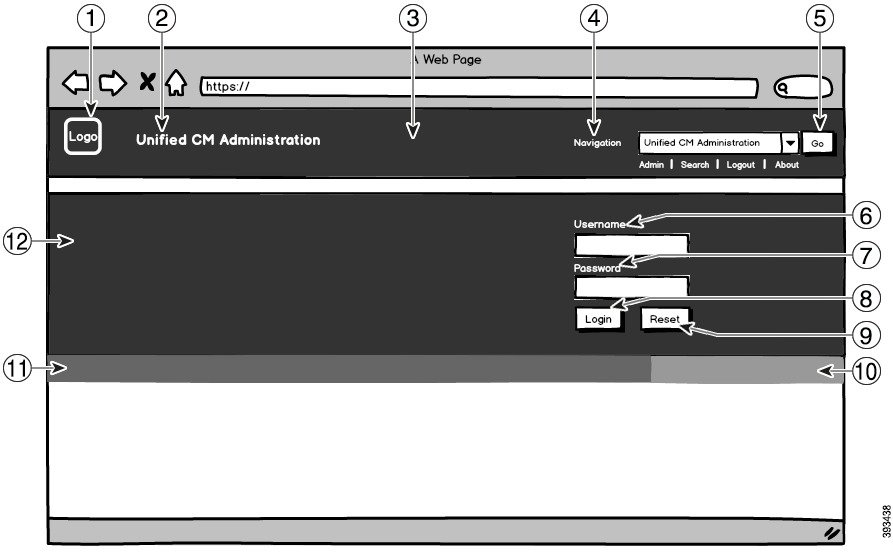
Page 638
Figure 11: Branding Options for Unified CM Administration Logged In Screen
The following table describes the callout options.
Table 53: User Interface Branding Options: Login Screen
Branding edits
Description
Item
To add your logo to Cisco Unified Communications
Manager, save your company logo as a 44x44 pixel
image with the following filename:
ciscoLogo12pxMargin.gif (44*44 pixels)
Note
If you also want to append your logo to the header
and login screen of the Self-Care Portal, you should
also save your logo as the 44x25 pixel
branding_logo.png file.
Company Logo
1
heading.heading.color
Unified CM Administration header font
color
2
Feature Configuration Guide for Cisco Unified Communications Manager, Release 15 and SUs
596
Custom Features
Branding File Requirements
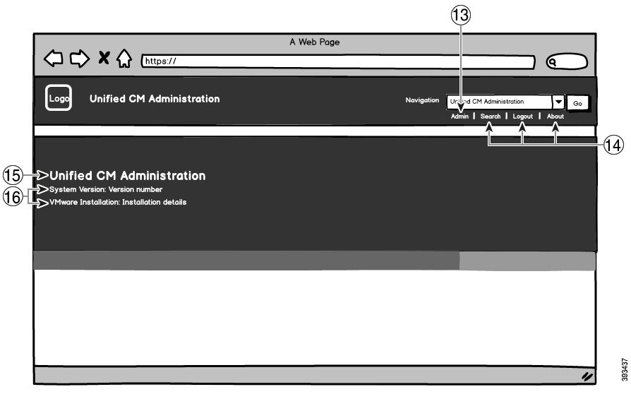
Page 639
Branding edits
Description
Item
You can use a single image or a combination of six
images to create a grading effect.
Single Image option—Save your header background
as a single image:
• brandingHeader.gif (20481 pixel)
Graded background option:—Save your header
background as six images for a graded effect:
• brandingHeaderBegLTR.gif (6521 pixel)
• brandingHeaderBegRTR.gif (6521 pixel)
• brandingHeaderEndLTR.gif (6521 pixel)
• brandingHeaderEndRTR.gif (6521 pixel)
• brandingHeaderMidLTR.gif (6521 pixel)
• brandingHeaderMidRTR.gif (652*1 pixel)
Header Background
3
header.navigation.color
Navigation text
4
header.go.font.color
header.go.background.color
header.go.border.color
Go button
5
splash.username.color
Username text
6
splash.password.color
Password text
7
splash.login.text.color
splash.login.back.ground.color
Login button
8
splash.reset.text.color
splash.reset.back.ground.color
Reset button
9
splash.hex.code.3
Bottom background color – right
10
splash.hex.code.2
Bottom background color – left
11
splash.hex.code.1
Banner
12
Table 54: User Interface Branding Options: Logged In Screen
Branding edits
Description
Item
header.admin.color
User text (for example, 'admin')
13
header.hover.link.color
Search, About and Login text
14
Feature Configuration Guide for Cisco Unified Communications Manager, Release 15 and SUs
597
Custom Features
Branding File Requirements
Page 640
Branding edits
Description
Item
splash.header.color
Unified CM Administration text heading
15
splash.reset.text.color
splash.version.color
System Version, VMware Installation
text
16
Branding Properties Editing Example
Branding properties can be edited by adding the hex code in the properties file
(BrandingProperties.properties). The properties file uses HTML-based hex code. For example,
if you want to change the color of the Navigation text item (callout item #4) to red, add the following code
to your properties file:
header.navigation.color="#FF0000"
In this code, header.navigation.color is the branding property that you want to edit, and "#FF0000" is the
new setting (red).
Feature Configuration Guide for Cisco Unified Communications Manager, Release 15 and SUs
598
Custom Features
Branding File Requirements
Page 641
C H A P T E R 48
Client Matter Codes and Forced Authorization
Codes
• Client Matter Codes and Forced Authorization Codes Overview, on page 599
• Client Matter Codes and Forced Authorization Codes Prerequisites, on page 599
• Client Matter Codes and Forced Authorization Codes Configuration Task Flow, on page 600
• Client Matter Codes and Forced Authorization Codes Interactions, on page 603
• Client Matter Codes and Forced Authorization Codes Restrictions, on page 604
Client Matter Codes and Forced Authorization Codes Overview
With client matter codes (CMCs) and forced authorization codes (FACs), you can effectively manage call
access and accounting. CMCs assist with call accounting and billing for clients, and FACs regulate the types
of calls that certain users can place.
CMCs force the user to enter a code; this action specifies that the call relates to a specific client matter. You
can assign client matter codes to customers, students, or other populations for call accounting and billing
purposes. FACs force the user to enter a valid authorization code that is assigned at a certain access level
before the call is completed.
Client Matter Codes and Forced Authorization Codes
Prerequisites
• Cisco Unified IP Phones that are running SCCP and SIP support CMC and FAC.
• The CMC and FAC tones play only on Cisco Unified IP Phones that are running SCCP or SIP;
TAPI/JTAPI ports; and MGCP FXS ports.
Feature Configuration Guide for Cisco Unified Communications Manager, Release 15 and SUs
599

Page 642
Client Matter Codes and Forced Authorization Codes
Configuration Task Flow
You can implement CMCs and FACs separately or together. For example, you may authorize users to place
certain classes of calls, such as long distance calls, and also assign the class of calls to a specific client. CMC
and FAC tones sound the same to the user; if you configure both codes, the feature prompts the user to enter
the FAC after the first tone and enter the CMC after the second tone.
Before you begin
• Review Client Matter Codes and Forced Authorization Codes Prerequisites, on page 599
Procedure
Purpose
Command or Action
After you finalize the list of CMCs that you
plan to use, add those codes to the database and
enable the CMC feature in route patterns.
To Configure Client Matter Codes, on page 600,
complete the following subtasks:
Step 1
• Add Client Matter Codes, on page 601
• Enable Client Matter Codes, on page 601
After you finalize the list of FACs and
authorization levels that you plan to use, add
To Configure Forced Authorization Codes, on
page 602, complete the following subtasks:
Step 2
those codes to the database and enable the FAC
feature in route patterns.
• Add Forced Authorization Codes, on page
602
• Enable Forced Authorization Codes, on
page 602
Configure Client Matter Codes
Procedure
Purpose
Command or Action
Determine unique client matter codes that you
want to use and add them to your system.
Add Client Matter Codes, on page 601
Step 1
Because the number of CMCs directly affects
the time that is required for your system to start
up, limit the number of CMCs to a maximum
of 60,000. If you configure more CMCs than
the maximum number, expect significant delays.
Enable client matter codes through a route
pattern.
Enable Client Matter Codes, on page 601
Step 2
Feature Configuration Guide for Cisco Unified Communications Manager, Release 15 and SUs
600
Custom Features
Client Matter Codes and Forced Authorization Codes Configuration Task Flow
Page 643
Add Client Matter Codes
Determine unique client matter codes that you want to use and add them to your system. Because the number
of CMCs directly affects the time that is required for your system to start up, limit the number of CMCs to a
maximum of 60,000. If you configure more CMCs than the maximum number, expect significant delays.
Procedure
Step 1
From Cisco Unified CM Administration, choose Call Routing > Client Matter Codes.
Step 2
Click Add New.
Step 3
In the Client Matter Code field, enter a unique code of no more than 16 digits that the user will enter when
placing a call.
Step 4
In the Description field, enter a client name if you want to identify the client matter code.
Step 5
Click Save.
Enable Client Matter Codes
Enable client matter codes through a route pattern.
Before you begin
Add Client Matter Codes, on page 601
Procedure
Step 1
From Cisco Unified CM Administration, choose Call Routing > Route/Hunt > Route Pattern.
Step 2
Perform one of the following tasks:
• To update an existing route pattern, enter search criteria, click Find, and choose a route pattern from the
resulting list.
• To create a new route pattern, click Add New.
Step 3
In the Route Pattern Configuration window, check the Require Client Matter Code check box.
Step 4
Click Save.
Feature Configuration Guide for Cisco Unified Communications Manager, Release 15 and SUs
601
Custom Features
Add Client Matter Codes
Page 644
Configure Forced Authorization Codes
Procedure
Purpose
Command or Action
Determine unique forced authorization codes
that you want to use and add them to your
system.
Add Forced Authorization Codes, on page 602
Step 1
Enable forced authorization codes through a
route pattern.
Enable Forced Authorization Codes, on page
602
Step 2
Add Forced Authorization Codes
Use this procedure to determine unique forced authorization codes that you want to use and add them to your
system. To successfully route a call, the user authorization level must be equal to or greater than the
authorization level that is specified for the route pattern for the call.
Procedure
Step 1
From Cisco Unified CM Administration, choose Call Routing > Forced Authorization Codes.
Step 2
In the Authorization Code Name field, enter a unique name that is no more than 50 characters.
This name ties the authorization code to a specific user or group of users.
Step 3
In the Authorization Code field, enter a unique authorization code that is no more than 16 digits.
Users enter this code when they place a call through an FAC-enabled route pattern.
Step 4
In the Authorization Level field, enter a three-digit authorization level in the range of 0 to 255.
Step 5
Click Save.
Enable Forced Authorization Codes
Use this procedure to enable forced authorization codes through a route pattern.
Procedure
Step 1
From Cisco Unified CM Administration, choose Call Routing > Route/Hunt > Route Pattern.
Step 2
Perform one of the following tasks:
• Click Find, and then choose a route pattern from the resulting list to update an existing route pattern.
• Click Add New to create a new route pattern.
Step 3
In the Route Pattern Configuration window, check the Require Forced Authorization Code check box.
Feature Configuration Guide for Cisco Unified Communications Manager, Release 15 and SUs
602
Custom Features
Configure Forced Authorization Codes
Page 645
Step 4
In the Authorization Level field, enter the authorization level value between 0 and 255.
The FAC level for the user must be greater than or equal to the configured level for the call to route successfully.
Step 5
Click Save.
ClientMatterCodesandForcedAuthorizationCodesInteractions
Table 55: Client Matter Codes and Forced Authorization Codes Interactions
Interaction
Feature
CDR Analysis and Reporting (CAR) allows you to run reports that provide call details
for client matter codes (CMCs), forced authorization codes (FACs), and authorization
levels.
CDR Analysis and
Reporting (CAR)
In most cases, your system can alert a CTI, JTAPI, or TAPI application that the user
must enter a code during a call. When a user places a call, creates an ad hoc conference,
or performs a consult transfer through a CMC- or FAC-enabled route pattern, the
user must enter a code after receiving the tone.
When a user redirects or blind transfers a call through a CMC- or FAC-enabled route
pattern, the user receives no tone, so the application must send the codes to Cisco
Unified Communications Manager. If your system receives the appropriate codes,
the call connects to the intended party. If your system does not receive the appropriate
codes, Cisco Unified Communications Manager sends an error to the application that
indicates which code is missing.
CTI, JTAPI, and
TAPI applications
Web Dialer supports CMCs and FACs in the following ways:
• A user can enter the destination number in the dial text box of the WD HTML
page or SOAP request, and then manually enter the CMC or FAC on the phone.
• A user can enter the destination number followed by the FAC or CMC in the
dial text box of the WD HTML page or SOAP request.
For example, if the destination number is 5555, the FAC is 111, and the CMC is 222,
a user can make a call by dialing 5555111# (FAC), 5555222# (CMC), or 5555111222#
(CMC and FAC).
Note
• WebDialer does not handle any validation for the destination number. The phone
handles the required validation.
• If a user does not provide a code or provides the wrong code, the call will fail.
• If a user makes a call from the WebApp with a DN that contains special
characters, the call goes successfully after stripping the special characters. The
same rules do not work in SOAP UI.
Cisco Web Dialer
Feature Configuration Guide for Cisco Unified Communications Manager, Release 15 and SUs
603
Custom Features
Client Matter Codes and Forced Authorization Codes Interactions
Page 646
Interaction
Feature
You can use speed dial to reach destinations that require a FAC, CMC, dialing pauses,
or additional digits (such as a user extension, a meeting access code, or a voicemail
password). When the user presses the configured speed dial, the phone establishes
the call to the destination number and sends the specified FAC, CMC, and additional
digits with dialing pauses inserted.
Speed Dial and
Abbreviated Speed
Dial
ClientMatterCodesandForcedAuthorizationCodesRestrictions
Table 56: Client Matter Codes and Forced Authorization Codes Restrictions
Description
Restriction
H.323 analog gateways do not support CMCs or FACs because these gateways cannot
play tones.
Analog gateways
Calls that are forwarded to a CMC- or FAC-enabled route pattern fail because no
user is present to enter the code. When a user presses the CFwdALL softkey and
enters a number that has CMC or FAC enabled on the route pattern, call forwarding
fails.
To minimize call-processing interruptions, test the number before you configure call
forwarding. To do this, dial the intended forwarding number; if you are prompted for
a code, do not configure call forwarding for that number. Advise users of this practice
to reduce the number of complaints that result from forwarded calls that do not reach
the intended destination.
Call forwarding
Calls that originate from a SIP trunk, H.323 gateway, or MGCP gateway fail if they
encounter a route pattern that requires CMCs or FACs and the caller is not configured
with Cisco Unified Mobility.
Cisco Unified
Mobility
The CMC and FAC feature on Cisco Mobility does not support an alternative number
as its dial via office (DVO) callback number. The DVO callback number must be the
number that is registered on the Mobility Identity window.
Dial via Office
callback number
CMCs and FACs do not work with failover calls.
Failover calls
After dialing the phone number, hearing-impaired users should wait one or two
seconds before entering the authorization or client matter code.
Hearing-impaired
users
Cisco does not localize CMCs or FACs. The CMC and FAC features use the same
default tone for any locale that is supported with Cisco Unified Communications
Manager.
Note
For Cisco Mobility, CMCs and FACs are localized.
Localization
Feature Configuration Guide for Cisco Unified Communications Manager, Release 15 and SUs
604
Custom Features
Client Matter Codes and Forced Authorization Codes Restrictions
Page 647
Description
Restriction
The CMC and FAC features do not support overlap sending because Cisco Unified
Communications Manager cannot determine when to prompt the user for the code.
If you check the Require Forced Authorization Code or the Require Client Matter
Code check box in the Route Pattern Configuration window, the Allow Overlap
Sending check box is automatically unchecked and vice-versa.
Overlap sending
You cannot configure CMCs or FACs for speed-dial buttons. You must enter the
code when the system prompts you to do so.
Speed-dial buttons
Feature Configuration Guide for Cisco Unified Communications Manager, Release 15 and SUs
605
Custom Features
Client Matter Codes and Forced Authorization Codes Restrictions
Page 648
Feature Configuration Guide for Cisco Unified Communications Manager, Release 15 and SUs
606
Custom Features
Client Matter Codes and Forced Authorization Codes Restrictions
Page 649
C H A P T E R 49
Custom Phone Rings and Backgrounds
• Custom Phone Rings Overview, on page 607
• Custom Phone Rings Prerequisites, on page 607
• Custom Phone Rings Configuration Task Flow, on page 608
• Custom Backgrounds, on page 610
• Custom Backgrounds Configuration Task Flow, on page 611
Custom Phone Rings Overview
Custom Phone Rings allows you to create customized phone rings and upload the customized files to the
Cisco Unified Communications Manager TFTP server where they can be accessed by Cisco Unified IP Phones.
Cisco Unified IP Phones ship with default ring types that are implemented in hardware: Chirp1 and Chirp2.
In addition, Cisco Unified Communications Manager provides the capability of uploading the following files
to phones:
PCM Files
Cisco Unified Communications Manager provides a default set of phone ring sounds that are implemented
in software as pulse code modulation (PCM) audio files. Each PCM file specifies a single ring type.
Ringlist.xml File
The Ringlist.xml file describes the list of ring options that are available for phones.
You can upload customized PCM audio files, such as custom ring tones and call back tones, as well as the
modified Ringlist.xml file to the TFTP directory in Cisco Unified Communications Manager.
Custom Phone Rings Prerequisites
The following prerequisites apply to Custom Phone Rings:
• In order to upload your custom phone rings, the Cisco TFTP service must be running.
• Any PCM files that you want to upload must meet a set of file requirements in order to be compatible
with Cisco Unified IP Phones. For details, review the topic PCM File Format Requirements, on page
609.
• The Ringlist.xml file must meet a set of formatting guidelines. For details, review the topic Ringlist.xml
File Format Requirements, on page 609.
Feature Configuration Guide for Cisco Unified Communications Manager, Release 15 and SUs
607

Page 650
Custom Phone Rings Configuration Task Flow
Before you begin
• Review Custom Phone Rings Prerequisites, on page 607
Procedure
Purpose
Command or Action
Create your customized PCM and Ringlist.xml
files.
Prepare Custom Phone Rings for Upload, on
page 608
Step 1
Upload customized files to the Cisco Unified
Communications Manager TFTP server.
Upload Custom Phone Rings to TFTP Server,
on page 608
Step 2
After the upload completes, restart the Cisco
TFTP service.
Restart TFTP Service, on page 609
Step 3
Prepare Custom Phone Rings for Upload
Procedure
Step 1
Use the file get tftp <tftp path> CLI command to download the existing Ringlist.xml file, in addition
to any PCM files that you want to modify.
Step 2
Create a PCM file for each ring type that you want to upload. For guidelines on PCM file compatibility with
Cisco Unified Communications Manager, see PCM File Format Requirements, on page 609.
Step 3
Use an ASCII editor to update the Ringlist.xml file with your new phone rings. For details on Ringlist.xml
file formatting requirements, see Ringlist.xml File Format Requirements, on page 609.
Upload Custom Phone Rings to TFTP Server
Before you begin
Prepare Custom Phone Rings for Upload, on page 608
Procedure
Step 1
From Cisco Unified OS Administration, choose Software Upgrades > TFTP > File Management.
Step 2
Click Upload File.
Step 3
Click Browse and select the Ringlist.xml file, as well as any PCM files that you want to upload.
Feature Configuration Guide for Cisco Unified Communications Manager, Release 15 and SUs
608
Custom Features
Custom Phone Rings Configuration Task Flow
Page 651
Step 4
Click Upload File.
Restart TFTP Service
Before you begin
Upload Custom Phone Rings to TFTP Server, on page 608
Procedure
Step 1
Log in to Cisco Unified Serviceability and choose Tools > Control Center - Feature Services.
Step 2
From the Server drop-down list, choose the server on which the Cisco TFTP service is running.
Step 3
Click the radio button that corresponds to the Cisco TFTP service.
Step 4
Click Restart.
PCM File Format Requirements
PCM files for phone rings must meet a set of requirements for proper playback on Cisco Unified IP Phones.
When creating or modifying your PCM files, you can use any standard audio editing packages that support
the following file format requirements:
• Raw PCM
• 8000 samples per second
• 8 bits per sample
• mu-law compression
• Maximum ring size: 16080 samples
• Number of samples in the ring must be evenly divisible by 240
• Ring starts and ends at the zero crossing
Ringlist.xml File Format Requirements
The Ringlist.xml file defines an XML object that contains a list of phone ring types. Each ring type contains
a pointer to the PCM file that is used for that ring type and the text that will display on the Ring Type menu
on a Cisco Unified IP Phone for that ring.
The CiscoIPPhoneRinglist XML object uses the following simple tag set to describe the information:
<CiscoIPPhoneRinglist>
<Ring>
<DisplayName/>
<FileName/>
</Ring>
</CiscoIPPhoneRinglist>
The following characteristics apply to the definition names:
Feature Configuration Guide for Cisco Unified Communications Manager, Release 15 and SUs
609
Custom Features
Restart TFTP Service
Page 652
• DisplayName defines the name of the custom ring for the associated PCM file that will display on the
Ring Type menu of the Cisco Unified IP Phone.
• FileName specifies the name of the PCM file for the custom ring to associate with DisplayName.
The DisplayName and FileName fields must not exceed 25 characters.
Tip
The following example shows a Ringlist.xml file that defines two phone ring types:
<CiscoIPPhoneRinglist>
<Ring>
<DisplayName>Analog Synth 1</DisplayName>
<FileName>Analog1.raw</FileName>
</Ring>
<Ring>
<DisplayName>Analog Synth 2</DisplayName>
<FileName>Analog2.raw</FileName>
</Ring>
</CiscoIPPhoneRinglist>
You must include the required DisplayName and FileName for each phone ring type. The Ringlist.xml file
can include up to 50 ring types.
Tip
Custom Backgrounds
You can also use the TFTP server to upload new custom background images to the phones in your network.
Phone users can select the images that you upload as their phone backgrounds. You can configure your system
so that phone users can select from an assortment of images or you can assign a specific background image
for all phone.
If you want your phone users to be able to customize their phone backgrounds, then you must prepare and
upload the following files to the TFTP server whenever you upload new images:
• Full-size background image—Refer to your phone documentation for image specifications, including
the image size (in pixels) and color-type, for your phone model.
• A thumbnail image—This is only required if you want your phone users to be able to choose their own
background image. Refer to your phone documentation for the thumbnail image specifications
• An edited List.xml file—This file contains a listing of the background images from which phone
users can select. You must add your new images to this file.
If you want to assign a specific image for all phones then you need to upload the main background image
only. In addition, you also must update the Common Phone Profile to direct the phones to use the image that
you assign.
Feature Configuration Guide for Cisco Unified Communications Manager, Release 15 and SUs
610
Custom Features
Custom Backgrounds

Page 653
Custom Backgrounds Configuration Task Flow
Complete these tasks to configure and upload customized background images for the phones in your deployment.
You can configure the system so that phone users can select from an assortment of images, or you can assign
a specific background image that displays on all phones.
Procedure
Purpose
Command or Action
Create your full-size background image and
corresponding thumbnail image (if required).
Create Phone Background Images, on page 612
Step 1
Refer to your phone documentation for image
specifications, including file type, image size
(in pixels) and color-type.
Note
The thumbnail is not required if you are
assigning a specific background image.
Update the List.xml file from the appropriate
TFTP directory with your new images. This is
Edit the List.xml file, on page 612
Step 2
required so that phone users see the new images
in their list of phone background options.
Note
This procedure is required only if you are
giving your users the option to choose their
own background. If you are assigning a specific
background image then there is no need to edit
this file.
Upload your files to the TFTP server.
Upload Backgrounds to TFTP Server, on page
613
Step 3
Restart the Cisco TFTP service in order to push
the images to your phones.
Restart the TFTP Server, on page 613
Step 4
Optional. By default, Cisco Unified
Communications Manager gives phone users
Assign Phone Background for Phone Users, on
page 614
Step 5
the option to select their own phone background
image. However, you can use the Common
Phone Profile to assign a specific background
image for all phones that use this Common
Phone Profile.
Feature Configuration Guide for Cisco Unified Communications Manager, Release 15 and SUs
611
Custom Features
Custom Backgrounds Configuration Task Flow
Page 654
Create Phone Background Images
Refer to your phone documentation for background image specifications and thumbnail image specifications.
This includes the image sizes (in pixels), file type, and the appropriate destination TFTP directory for that
phone model (the TFTP directory is based on the image specifications).
• If you want phone users to have the option to use, or not use, the image that you upload, you must prepare
both a full-size image and a thumbnail image according to the specifications for that particular phone
model.
• If you want to assign the image to specific phones, you need the full-size image only.
What to do next
If you want phone users to be able to choose their own background image, Edit the List.xml file, on page 612.
If you want to assign a specific background image, you don't need to update the List.xml file. Proceed to
Upload Backgrounds to TFTP Server, on page 613
Edit the List.xml file
If you want phone users to be able to choose their background images, use this procedure to add any new
background images that you upload to the existing List.xml file. Each TFTP image directory contains a
List.xml file that gets used by the phones that use that TFTP directory. This file points to the specific
background and thumbnail image for each background option and can include up to 50 background images.
The images are listed using the order in which they appear on the phone. For each image, the file contains an
<ImageItem> element that includes these two attributes:
• Image: Uniform resource identifier (URI) that specifies where the phone obtains the thumbnail image
that will appear on the Background Images menu of a phone.
• URL: URI that specifies where the phone obtains the full size image.
Example:
The following example (for a Cisco Unified IP Phone 7971G-GE and 7970G) shows a List.xml file that
defines two images. The required Image and URL attributes must be included for each image. The TFTP URI
that displays in the example is the only supported method for linking to full size and thumbnail images as
HTTP URL support is not provided.
<CiscoIPPhoneImageList>
<ImageItem Image=”TFTP:Desktops/320x212x12/TN-Fountain.png”
URL=”TFTP:Desktops/320x212x12/Fountain.png”/>
<ImageItem Image=”TFTP:Desktops/320x212x12/TN-FullMoon.png”
URL=”TFTP:Desktops/320x212x12/FullMoon.png”/>
</CiscoIPPhoneImageList
Procedure
Step 1
Log in to the Command Line Interface
Step 2
Run the file get tftp <filename> CLI command where <filename> represents the file and filepath of the
List.xml file for the appropriate TFTP directory.
Feature Configuration Guide for Cisco Unified Communications Manager, Release 15 and SUs
612
Custom Features
Create Phone Background Images
Page 655
Note
Make sure that you download the List.xml file from the appropriate TFTP directory as each image directory
has its own file. Refer to your phone documentation for information on the appropriate TFTP directory for
that phone model as the directory is based on the image specifications.
Step 3
Edit the xml file with a new <ImageItem> element for each new background option that you want to add.
Upload Backgrounds to TFTP Server
Use this procedure to upload new phone background files to the TFTP server.
• If you want your phone users to be able to choose their own background image, then you must upload
your full-size background image, a thumbnail image, and the updated List.xml file.
• If you are assigning a specific background image, you need to upload the full-size background image
only.
Procedure
Step 1
From Cisco Unified OS Administration, choose Software Upgrades > TFTP File Management
Step 2
Click Upload File and do the following:
a)
Click Choose File and select the background file that you want to upload.
b) In the Directory field, enter the appropriate TFTP directory for that phone model. The TFTP directory
corresponds to the image size and color type. Refer to your phone documentation for images specification.
c)
Click Upload File
d) Repeat these steps to upload both the thumbnail image and list.xml files as well. These files should
be loaded to the same TFTP directory as the main background image.
Step 3
Click Close.
Restart the TFTP Server
After you have uploaded your custom files to the TFTP directory, restart the Cisco TFTP server to push the
files to the phones.
Procedure
Step 1
Log in to Cisco Unified Serviceability and choose Tools > Control Center - Feature Services.
Step 2
From the Server drop-down list, choose the server on which the Cisco TFTP service is running.
Step 3
Click the radio button that corresponds to the Cisco TFTP service.
Step 4
Click Restart.
Feature Configuration Guide for Cisco Unified Communications Manager, Release 15 and SUs
613
Custom Features
Upload Backgrounds to TFTP Server
Page 656
Assign Phone Background for Phone Users
By default, Cisco Unified Communications Manager allows phone users to customize their own phone
background image. However, you can use the Common Phone Profile setting to assign a specific background
image for all phones that use this Common Phone Profile.
Procedure
Step 1
From Cisco Unified CM Administration, choose Device > Device Settings > Common Phone Profile.
Step 2
Do one of the following:
• Click Find and select the Common Phone Profile that your phones use.
• Click Add New to create a new Common Phone Profile.
Step 3
If you want users to be able to choose their background image, make sure that the Enable End User Access
to Phone Background Image Setting check box is checked (this is the default setting).
Step 4
If you want to assign a specific background image for phones that use this profile:
• Uncheck the Enable End User Access to Phone Background Image Setting check box.
• In the Background Image text box, enter the filename of the image file that you want to assign. Also,
check the Override Enterprise Settings check box that corresponds to this text box.
Step 5
Complete any remaining fields in the Common Phone Profile window. For help with the fields and their
settings, refer to the online help.
Step 6
Click Save.
If you have assigned a specific background image, all phones that use this Common Phone Profile will use
the image that you specify.
What to do next
If you have created a new Common Phone Profile, reconfigure your phones so that they use this profile. For
details on how to configure phones in Cisco Unified Communications Manager, see the "Configure Endpoint
Devices" section of the System Configuration Guide for Cisco Unified Communications Manager.
If you have a large number of phones to assign, use the Bulk Administration Tool to assign a Common Phone
Profile to a large number of phones in a single operation. For details, see the Bulk Administration Guide for
Cisco Unified Communications Manager.
Tip
After you complete your configuration, reset your phones.
Note
Feature Configuration Guide for Cisco Unified Communications Manager, Release 15 and SUs
614
Custom Features
Assign Phone Background for Phone Users


Page 657
C H A P T E R 50
Music On Hold
• Music On Hold Overview, on page 615
• Interwork External Multicast MOH to Unicast MOH, on page 619
• Music On Hold Prerequisites, on page 620
• Music On Hold Configuration Task Flow, on page 620
• Unicast and Multicast Audio Sources, on page 627
• Music On Hold Interactions, on page 629
• Music On Hold Restrictions, on page 630
• Music On Hold Troubleshooting, on page 632
Music On Hold Overview
Use the integrated Music On Hold (MOH) feature to place on-net and off-net users on hold with music from
a streaming source. This source makes music available to any on-net or off-net device that you place on hold.
On-net devices include station devices and applications that an interactive voice response (IVR) or call
distributor places on hold, consult hold, or park hold. Off-net users include those users who are connected
through Media Gateway Control Protocol (MGCP) or Skinny Call Control Protocol (SCCP) gateways, Cisco
IOS H.323 gateways, and Cisco IOS Media Gateway Control Protocol gateways. The system also makes the
Music On Hold feature available for Cisco IP POTS phones that connect to the Cisco IP network through
Foreign Exchange Station (FXS) ports on Cisco IOS H.323 or MGCP and for Cisco MGCP or SCCP gateways.
Start Cisco Unified Communications Manager to create a media resource manager. Music On Hold server
registers to the media resource manager with its music on hold resources. Music On Hold server is a software
application that provides music on hold audio sources and connects a music on hold audio source to multiple
streams.
When an end device or feature places a call on hold, Cisco Unified Communications Manager connects the
held device to a music resource. When the held device is retrieved, it disconnects from the music on hold
resource and resumes normal activity.
Caller-Specific Music On Hold
For SIP calls that a phone receives over the SIP trunk, Cisco Unified Communications Manager can use a
different MOH audio source.
Feature Configuration Guide for Cisco Unified Communications Manager, Release 15 and SUs
615

Page 658
An external application, such as the Cisco Unified Customer Voice Portal (CVP) contact center solution,
determines the most appropriate MOH audio source based on the caller ID, dialed number, or IVR interaction
when a call is received from the public switched telephone network (PSTN).
For details, see the Cisco Unified Customer Voice Portal documentation at http://www.cisco.com/c/en/us/
support/customer-collaboration/unified-customer-voice-portal/tsd-products-support-series-home.html.
Increased Capacity of IP Voice Media Streaming Application and Expanded
MOH Audio Source
Cisco IP Voice Media Streaming application is installed automatically when you install Cisco Unified
Communications Manager. Activate this application to enable the Music On Hold (MOH) feature.
With this release, the capacity of Cisco Unified Communications Manager to support unique and concurrent
MOH audio sources, while the Music On Hold service is running on the MOH server, is increased from 51
to 501. The MOH audio sources are numbered from 1 to 501 with the fixed MOH audio source remaining at
the number 51.
The fixed MOH device cannot use an audio source that connects through a USB MOH device, because Cisco
Unified Communications Manager does not support USB when running on VMware. Use of the fixed MOH
USB device is not supported on VMware. However, provision the external sound device for use with
deployments that utilize Cisco Unified Survivable Remote Site Telephony (SRST) multicast MOH.
You can configure each MOH audio source to use a custom announcement as an initial greeting and/or an
announcement that is played periodically to callers who are hearing the music. Cisco Unified Communications
Manager provides 500 custom announcements that you can use on one or multiple MOH audio sources. These
announcements are not distributed between the Cisco Unified Communications Manager servers within a
cluster. You have to upload these custom announcement files to each server that provides the MOH and
announcement services. You must also upload each custom music file for MOH audio sources to each server.
Performance Impact of Media Devices with Services
The Cisco IP Voice Media Streaming application runs as a service for four media devices—annunciator
(ANN), software conference bridge, Music On Hold (MOH), and software media termination point. Activate
this service on a Cisco Unified Communications Manager server as coresident with call processing. When
you activate this service, ensure that you configure these media devices for limited capacity to avoid any
impact on the call processing. The default settings for the media devices are defined based on this coresident
operation. You can adjust these settings by reducing the use of one or more media devices to increase other
settings.
For example, if you are not using software media termination point devices, you can choose the Run Flag
setting for the SW MTP to False, select System > Service Parameters > Cisco IP Voice Media Streaming
App service > MTP Parameters , and add the MTP Call Count setting to Media Resource > MOH Server >
Maximum Half Duplex Streams configuration. Depending on the call traffic, you can modify the default
settings. However, monitor the server performance activity for CPU, memory, and IO wait. For higher capacity
clusters, such as the ones using 7500 user OVA configuration, it is possible to increase the default media
device settings for Call Count by 25%.
For installations where you expect high usage of the media devices, such as Music On Hold, or where high
call volumes require higher number of media connections, activate the Cisco IP Voice Media Streaming
application service on one or more of the Cisco Unified Communications Manager servers which do not have
call processing activated. Activating this service limits the impact of media device usage to other services,
Feature Configuration Guide for Cisco Unified Communications Manager, Release 15 and SUs
616
Custom Features
Increased Capacity of IP Voice Media Streaming Application and Expanded MOH Audio Source
Page 659
such as call processing. Then, you can increase the configuration settings for maximum number of calls for
the media devices.
When you activate Cisco IP Voice Media Streaming application as co-resident with Cisco Unified
Communications Manager service, it can impact call processing performance. To increase the capacity settings
for Music On Hold or annunciator from the default settings, it is suggested to activate Cisco IP Voice Media
Streaming application on a server without activating Cisco Unified Communications Manager.
The CPU performance is impacted by MOH when active callers are on hold or when multicast MOH audio
streams are configured.
Table 57: General Performance Results
CPU Performance
Configuration Notes
25–45% (7500 user OVA configuration)
Dedicated MOH server, 1000 held calls, 500 MOH
sources with greeting and periodic announcements.
25–45% (7500 user OVA configuration)
Native call queuing with dedicated MOH server and
annunciator server, 1000 queued calls, 500 MOH
sources with greeting and periodic announcements.
An annunciator can play up to 300 simultaneous
greeting announcements.
15–35% (7500 user OVA configuration)
Dedicated MOH server, 500 held calls, 500 MOH
sources with greeting and periodic announcements.
Table 58: Extrapolated Recommendations
Recommendation Limit
Configuration
MOH: 500 held callers, 100 MOH sources, and 48 to
64 annunciator callers.
When Cisco IP Voice Media Streaming application
is co-resident with Cisco Unified Communications
Manager on 2500 OVA (moderate call processing).
MOH: 750 held callers, 250 MOH sources, and 250
annunciator callers.
When Cisco IP Voice Media Streaming application
is a dedicated server on 2500 OVA.
MOH: 500 held callers, 250 MOH sources, and 128
annunciator callers.
When Cisco IP Voice Media Streaming application
is co-resident with Cisco Unified Communications
Manager on 7500/10K OVA (moderate call
processing).
MOH: 1000 held callers, 500 MOH sources, and
300-700 annunciator callers (with 1 MOH codec).
Note
Reduce annunciator to 300 for two MOH codecs.
When Cisco IP Voice Media Streaming application
is a dedicated server on 7500/10K OVA.
These recommendations are specific to MOH/ANN devices. If you combine these devices with the software
media termination point (MTP) and call forward busy (CFB) devices, reduce the limits to provide streams.
Note
Feature Configuration Guide for Cisco Unified Communications Manager, Release 15 and SUs
617
Custom Features
Performance Impact of Media Devices with Services

Page 660
Configuration Limitations for Capacity Planning
The Cisco IP Voice Media Streaming application and Self Provisioning IVR services use a media kernel
driver to create and control Real-time Transfer Protocol (RTP) streams. This media kernel driver has a capacity
of 6000 streams. These streams allow the media devices and IVR to make resource reservations.
These reservations are based on the following capacity calculations:
Capacity
Media Device
(Call Count service parameter) * 3
Where 3 indicates total of receiving (RX) and transmitting (TX) calls for
endpoint and 1 for .wav file.
Annunciator
(Call Count service parameter) * 2
Where 2 indicates total streams of RX and TX endpoints.
Software Conference Bridge
(Call Count service parameter) * 2
Where 2 indicates total streams of RX and TX endpoints.
Software Media Termination
Point
((Maximum Half Duplex Streams) * 3) + (501 * 2 * [number of enabled MOH
codecs])
Where:
• (Maximum Half Duplex Streams) is a configuration setting on the MOH
device configuration administration web page.
• 3 indicates total steams of RX, TX, and greeting announcement .wav
file.
• 501 indicates the maximum number of Music On Hold (MOH) sources.
• 2 indicates music .wav stream and possible multicast TX stream.
• [number of enabled MOH codecs] is based on how many MOH codecs
are enabled in the Cisco IP Voice Media Streaming application service
parameters.
Music On Hold
(500 * 2)
Where 500 indicates callers, and 2 indicates total streams from RX and TX
streams.
Self Provisioning IVR
Service
Hence, to enable MOH to support a maximum of 1000 callers, use the following equation: 1000 * 3 +
501 * 2 * 1 = 4002 driver streams with one enabled codec and 1000 * 3 +501 * 2 * 2 =
5004 with two enabled codecs. Reduce the remaining devices and deactivate the Self Provisioning IVR
service to limit total reservations to 6000, which allows the MOH device to make these reservations. It may
also require that you do not activate the Self Provisioning IVR service on the same server with Cisco IP Voice
Media Streaming application.
If configuration settings of the media devices exceed the capacity of the media device driver, the media devices
that register with the device driver first will be able to reserve their required stream resources. The media
devices that register later are restricted to fewer than requested stream resources. The later registered media
Feature Configuration Guide for Cisco Unified Communications Manager, Release 15 and SUs
618
Custom Features
Configuration Limitations for Capacity Planning
Page 661
devices result in logging some alarm messages and automatically reducing the call count for the restricted
media device.
A media kernel driver with a capacity of 6000 streams might not support that many simultaneous media device
connections.
Note
Interwork External Multicast MOH to Unicast MOH
With this release, you can configure a Cisco Unified Survivable Remote Site Telephony (SRST) router as an
audio source. This router provides multicast MOH audio for devices that are capable of multicast reception.
In this approach, devices act as if Cisco Unified Communications Manager is sending the multicast MOH
audio. However, devices that are capable of only the unicast reception cannot hear the MOH audio that an
external MOH source (for example, Cisco Unified SRST router) sends. Examples of devices that are capable
of unicast reception only can be public switched telephone network (PSTN) phones, destination to session
border controllers (SBC), and Session Initiation Protocol (SIP) trunks.
In this release of Cisco Unified Communications Manager, this feature is enhanced to receive multicast MOH
audio from an external audio source and send it as unicast MOH audio. Cisco Unified Communications
Manager uses this feature to play multicast MOH audio as unicast MOH for the devices that are capable of
unicast MOH reception only. Examples of an external MOH audio source can be a Cisco Unified SRST router
or software that can send multicast MOH audio.
An administrator configures the fields for this feature from Cisco Unified CM Administration Music On
Hold Audio Source Configuration window.
• This feature has no impact on existing functionality of playing multicast MOH audio using an external
audio source for the devices that are capable of multicast reception.
• For the unicast media connection, Cisco Unified Communications Manager MOH Server plays the initial
announcement and periodic announcement even if you configure the MOH audio source with external
multicast source.
Note
Configuration Tips for the Codec-Specific Inbound Audio Stream
Configure an external multicast audio source, such as Cisco Unified SRST router, to MOH server for streaming
the required audio feed.
To configure an external multicast audio source, such as a Cisco Unified SRST router, configure the Source
IPv4 Multicast Address and Source Port Number fields in the MOH Audio Source Configuration window.
• Cisco Unified Communications Manager listens to multicast G.711 mu-law stream on external multicast
IP address and port that you configured on the MOH Audio Source configuration window. An MOH
server can transcode between the G.711 mu-law or a-law or L16 256K wideband MOH codecs. The
external multicast RTP stream uses G.711 mu-law codec for MOH as a source for G.711 mu-law or a-law
or L16 256K wideband MOH codecs. For G.711 a-law and wideband calls, Cisco Unified Communications
Manager MOH server transcodes the inbound G.711 mu-law stream to outbound G.711 a-law or wideband
stream before sending it to the device.
Feature Configuration Guide for Cisco Unified Communications Manager, Release 15 and SUs
619
Custom Features
Interwork External Multicast MOH to Unicast MOH

Page 662
• Cisco Unified Communications Manager listens to multicast G.729 stream on external multicast IP and
port value added with four that is configured on the MOH audio source configuration window. For
example, if you configure an MOH audio Source with 239.1.1.1:16384, Cisco Unified Communications
Manager listens to G.711 mu-law stream on 239.1.1.1:16384 and G.729 stream on 239.1.1.1:16388 (port
value added with four). An MOH server cannot transcode for G.729 codecs. Callers who are using MOH
G.729 codec require an external multicast RTP stream using G.729 or G.729a codec.
Music On Hold Prerequisites
• Before you configure multicast, ensure that you configure MOH server and audio sources. If you want
to use fixed audio source, configure it before you configure multicast.
• Make sure to decide whether you are going to do unicast or multicast Music On Hold
• It is crucial to plan the capacity of the deployed and configured hardware and ensure that it can support
the anticipated call volume of the network. You need to know the hardware capacity for MOH resources
and consider the implications of multicast and unicast MOH in relation to this capacity. Ensure that
network call volumes do not exceed these limits. When MOH sessions reach these limits, an additional
load can result in poor MOH quality, erratic MOH operation, or loss of MOH functionality.
• If you use multicast MOH and the devices that listen to multicast MOH streams are not in the same IP
network, you must enable multicast routing in the IP network. Take care when you enable the multicast
routing to avoid the potential flooding of parts of the network with wrongly sent multicast packets
(specially, across WAN links). Disable multicasts on interfaces on which the multicast MOH packets
are not required and use the Max Hops parameter.
• For detailed information on planning your Music On Hold deployment, including server capacities, refer
to the Music On Hold capacities topics in the Cisco Collaboration System Solution Reference Network
Design.
Music On Hold Configuration Task Flow
Complete these tasks to configure Music On Hold (MOH) for your system.
Procedure
Purpose
Command or Action
Activate the Cisco IP Voice Media Streaming
Service Application service to enable Music
On Hold.
Activate Cisco IP Voice Media Streaming, on
page 621
Step 1
Configure basic server settings for the MOH
server.
Configure Music On Hold Server, on page 622
Step 2
Optional. Upload your own audio files to make
them available as MOH audio streams.
Upload Audio File for Music On Hold, on page
622
Step 3
Feature Configuration Guide for Cisco Unified Communications Manager, Release 15 and SUs
620
Custom Features
Music On Hold Prerequisites
Page 663
Purpose
Command or Action
Configure Music On Hold audio streams. You
can also associate an uploaded audio files to an
MOH audio stream.
Configure Music On Hold Audio Source, on
page 623
Step 4
Configure the fixed Music On Hold audio
source. The system supports a single fixed
MOH audio source (stream 51).
Configure Fixed Music On Hold Audio Source,
on page 624
Step 5
Assign the Music On Hold service to a Media
Resource Group. The group compiles the media
Add MOH to Media Resource Group, on page
624
Step 6
resources that are available to an endpoint in a
call.
Assign your Media Resouce Groups to a
prioritized Media Resource Group List.
Configure Media Resource Group List, on page
625
Step 7
Make Music On Hold available to endpoints by
assigning the Media Resource Group List to a
device or device pool.
Add Media Resources to Device Pool, on page
625
Step 8
Optional. Configure optional Music On Hold
parameters such as default codecs and default
audio streams for calls on hold.
Configure MOH Service Parameters, on page
626
Step 9
Activate Cisco IP Voice Media Streaming
The Cisco IP Voice Media Streaming Application service must be Activated in order to use Music On
Hold.
During installation, Unified Communications Manager installs and configures a default Music On Hold audio
source. Music On Hold functionality can proceed by using the default audio source.
Note
Procedure
Step 1
From Cisco Unified CM Administration, choose Tools > Service Activation.
Step 2
Choose a server from the Server drop-down list.
Step 3
Under CM Services , make sure the Cisco IP Voice Media Streaming App service is Activated. If the
service is deactivated, check the service and click Save.
Feature Configuration Guide for Cisco Unified Communications Manager, Release 15 and SUs
621
Custom Features
Activate Cisco IP Voice Media Streaming

Page 664
Configure Music On Hold Server
Before you begin
Make sure one or multiple Music On Hold (MOH) servers are available.
The Cisco Unified Communications Manager MOH server is automatically added when the Cisco IP Voice
Media Streaming Application service is activated.
Note
Procedure
Step 1
From Cisco Unified CM Administration, choose Media Resources > Music On Hold Server.
Step 2
Click Find and select the Music On Hold server that you want to update.
Step 3
Select the Host Server.
Step 4
Enter a descriptive Music On Hold Server Name along with a Description.
Step 5
Select the Device Pool you want to use for this server.
Step 6
Configure server capacity by configuring the following fields:
• Maximum Half Duplex Stream—Set this to the maximum number of devices that can be on unicast
music on hold that is streamed from this music on hold server at any given time. You can use the following
formula to calculate the maximum:
Note
(Server and deployment capacity) – ([Number of multicast MOH sources] * [Number of
enabled MOH codecs])
• Maximum Multi-cast Connections—Set this to a value that is greater than or equal to the number of
devices that might be placed on multicast MOH at any given time.
Step 7
(Optional) To enable multi-casting, check the Enable Multi-cast Audio Sources on this MOH Server check
box, and configure the multicast IP address ranges.
Step 8
Configure the additional fields in the Music On Hold Server Configuration window. For help with the fields
and their settings, see the online help.
Step 9
Click Save.
Upload Audio File for Music On Hold
Use this procedure if you want to upload customized audio files that you can make available as Music On
Hold audio streams.
Procedure
Step 1
From Cisco Unified CM Administration, choose Media Resources > MOH Audio File Management.
Feature Configuration Guide for Cisco Unified Communications Manager, Release 15 and SUs
622
Custom Features
Configure Music On Hold Server

Page 665
Step 2
Click Upload File.
Step 3
Click Choose File and browse to the file you want to upload. Once you've selected the file, click Open.
Step 4
Click Upload.
The Upload Result window shows the result of the upload. The uploading procedure uploads the file and
performs audio conversions to create codec-specific audio files for MOH. Depending on the size of the original
file, processing may take several minutes to complete.
Step 5
Click Close to close the Upload Result window.
Step 6
Repeat this procedure if you want to upload additional audio files.
Note
When you import an audio source file, Unified Communications Manager processes the file and converts the
file to the proper formats for use by the Music On Hold server. Following are examples of valid input audio
source files:
• 16-bit PCM .wav file
• Stereo or mono
• Sample rates of 48 kHz, 44.1 kHz, 32 kHz, 16 kHz, or 8 kHz
Note
MOH audio source files do not automatically propagate to other MOH servers in a cluster. You must upload
an audio source file to each MOH server or each server in a cluster separately
Configure Music On Hold Audio Source
Use this procedure to configure Music On Hold audio sources. You can configure audio streams and associate
uploaded files to an audio stream. You can configure up to 500 audio streams.
If a new version of an audio source file is available, perform the update procedure to use the new version.
Note
Procedure
Step 1
From Cisco Unified CM Administration, choose Media Resources > Music On Hold Audio Source.
Step 2
Do either of the following:
• Click Find and select an existing audio stream.
• Click Add New to configure a new stream.
Step 3
From the MOH Audio Stream Number, select an audio stream.
Step 4
Enter a unique name in the MOH Audio Source Name field.
Step 5
Optional. Check the Allow Multi-casting check box if you want to allow this file to be multi-casted.
Step 6
Configure the audio source:
Feature Configuration Guide for Cisco Unified Communications Manager, Release 15 and SUs
623
Custom Features
Configure Music On Hold Audio Source

Page 666
• Check the Use MOH WAV file source radio button and from the MOH Audio Source File, select the
file you want to assign.
• Check the Rebroadcast External Multicast Source radio button and enter the multicast source IP
Address details.
Step 7
In the Announcement Settings for Held and Hunt Pilot Calls section, assign the announcements that you
want to use for this audio source.
Step 8
Configure the remaining fields in the Music On Hold Audio Source Configuration window. For help with
the fields and their settings, see the online help.
Step 9
Click Save.
Configure Fixed Music On Hold Audio Source
For each cluster, you may define one fixed audio source (Source 51). You must set up the fixed audio source
that is configured per cluster on each MOH server. The fixed audio source originates from a fixed device that
uses the local computer audio driver.
Procedure
Step 1
From Cisco Unified CM Administration, choose Media Resources > Fixed MOH Audio Source.
Step 2
Optional. Check the Allow Multi-casting check box if you want to allow this audio source to be multi-casted.
Step 3
Check the Enable check box to enable the fixed audio source. When you check this check box, a Name is
required.
Step 4
In the Announcement Settings for Held and Hunt Pilot Calls area, configure announcements for this audio
source.
Step 5
Configure the fields in the Fixed MOH Audio Source Configuration window. For help with the fields and
their settings, see the online help.
Step 6
Click Save.
Add MOH to Media Resource Group
A Media Resource Group is a logical grouping of media resources. You may associate a media resource group
with a geographical location or a site, as required. You can also form media resource groups to control server
usage, or unicast or multicast service type.
Procedure
Step 1
From Cisco Unified CM Administration, choose Media Resources > Media Resource Group.
Step 2
Do either of the following:
• Click Find and select an existing group.
• Click Add New to create a new group.
Feature Configuration Guide for Cisco Unified Communications Manager, Release 15 and SUs
624
Custom Features
Configure Fixed Music On Hold Audio Source
Page 667
Step 3
Enter a Name and Description.
Step 4
In the Available Media Resources list, select the Music On Hold resource and use the down arrow to add
the resource to the Selected Media Resources. Repeat this step for the other media resources you want to
assign to this group.
Step 5
(Optional) Check the Use Multi-cast for MOH Audio check box if you want to allow Music On Hold
multi-casting.
Step 6
Click Save.
Configure Media Resource Group List
Media Resource Group List lists the prioritized media resource groups. An application can select required
media resources from among ones that are available according to the priority order that is defined in a media
resource group list.
Procedure
Step 1
From Cisco Unified CM Administration, choose Media Resources > Media Resource Group List.
Step 2
Do either of the following:
• Click Find and select an existing media resource group list.
• Click Add New to create a new media resource group list.
Step 3
Enter a Name for the list.
Step 4
From the Available Media Resource Groups list, select the groups you want to add to this list and use the
down arrow to move them to Selected Media Resource Groups.
Step 5
In the Selected Media Resource Groups list use the up and down arrows to the right of the list to edit the
prioritized order of groups.
Step 6
Click Save.
Add Media Resources to Device Pool
You can make MOH available to devices by assigning the media resource group list that contains the MOH
resource to a device or to the device pool.
The device in a call will use the media resource group list that is assigned to the device in the Phone
Configuration window. If none is assigned, it will use the media resource group list for the device pool that
is used for the call.
Note
Feature Configuration Guide for Cisco Unified Communications Manager, Release 15 and SUs
625
Custom Features
Configure Media Resource Group List

Page 668
Procedure
Step 1
From Cisco Unified CM Administration, do either of the following:
• Choose System > Device Pool.
• Choose Device > Phone.
Step 2
Click Find and select an existing phone or an existing device pool.
Step 3
From the Media Resource Group List drop-down list, select the media resource group list that contains the
Music On Hold resource.
Step 4
Complete the remaining fields in the configuration window. For more information on the fields and their
configuration options, see Online Help.
Step 5
Click Save.
Configure MOH Service Parameters
Use this procedure to configure optional service parameters for Music On Hold (MOH). For many deployments
the default settings will be sufficient.
Procedure
Step 1
In Cisco Unified CM Administration, choose System > Service Parameters.
Step 2
From the Server drop-down list, select the server.
Step 3
From the Service drop-down list, select Cisco IP Voice Media Streaming.
Step 4
From the Clusterwide Parameters (Parameters that apply to all servers) area, configure optional MOH
service parameters.
Step 5
Click Save.
Step 6
From the Service drop-down list, select Cisco CallManager.
Step 7
Configure optional MOH parameters. For example, under Clusterwide Parameters (Service), you can assign
the default audio sources for Hold.
Step 8
Click Save.
Note
All parameters apply only to the current server except parameters that are in the cluster-wide group.
View Music on Hold Audio File
View existing Music On Hold audio files that are stored on the system.
Feature Configuration Guide for Cisco Unified Communications Manager, Release 15 and SUs
626
Custom Features
Configure MOH Service Parameters
Page 669
Procedure
Step 1
In Cisco Unified CM Administration, choose Media Resources > MOH Audio File Management.
The Music On Hold Audio File Management window appears.
Step 2
View the following information for each record:
• Check box—If the audio file can be deleted, a check box appears before the File Name column.
• File Name—This column displays the audio file name.
• Length—This column displays the audio file length in minutes and seconds.
• File Status—This column displays one of the following statuses of an audio file:
• Translation Complete—This status appears after a file is uploaded successfully and is available
for use as audio files for a music on hold audio source.
• In Use—This status appears after you add a Music On Hold audio source that uses this audio file
as its MOH audio source file.
Note
You cannot a delete a file with In Use status.
Unicast and Multicast Audio Sources
Unicast Music On Hold is the system default option. However, you need to configure for multicast, if required.
Both multicast and unicast configurations present the same audio-source behavior to held parties. Each audio
source is used once, and the stream is split internally and is sent to the held parties. The only difference between
multicast and unicast, in this case, is how the data is sent over the network.
Table 59: Differences Between Unicast and Multicast Audio Sources
Multicast Audio Source
Unicast Audio Source
Consists of streams that are sent from the MOH server
to a multicast group IP address. Endpoints that request
an MOH audio stream can join multicast MOH, as
needed.
Consists of streams that are sent directly from the
MOH server to the endpoint that requests an MOH
audio stream.
A multicast MOH stream is a point-to-multipoint,
one-way audio RTP stream between the MOH server
and the multicast group IP address.
A unicast MOH stream is a point-to-point, one-way
audio RTP stream between the server and the endpoint
device.
Enables multiple users to use the same audio source
stream to provide MOH.
Unicast MOH uses a separate source stream for each
user or connection. As more endpoint devices go on
hold through a user or network event, the number of
MOH streams increases.
Feature Configuration Guide for Cisco Unified Communications Manager, Release 15 and SUs
627
Custom Features
Unicast and Multicast Audio Sources
Page 670
Multicast Audio Source
Unicast Audio Source
For multicast users, this announcement is not heard.
An MOH audio source may be configured with an
initial (greeting) announcement, which will be played
to unicast held parties. For unicast MOH users, this
announcement is heard from the beginning.
Multicast MOH conserves system resources and
bandwidth.
The additional MOH streams can have a negative
effect on network throughput and bandwidth.
Can be problematic in situations in which a network
is not enabled for multicast or the endpoint devices
are incapable of processing multicast.
Extremely useful in networks in which multicast is
not enabled or devices are incapable of multicast.
Includes managing devices, IP addresses, and ports.
Includes managing devices only.
Administrators must define at least one audio source
to allow multicasting. To define Music On Hold
servers for multicast, first define the server to allow
multicasting.
No requirement to define the Music On Hold server.
Functions only if both media resource groups and
media resource group lists are defined to include a
multicast Music On Hold server. For media resource
groups, you must include a Music On Hold server that
is set up for multicast. These servers are labeled as
(MOH) [Multicast]. Also, check the Use Multicast
for MOH Audio check box when you define a media
resource group for multicast.
Functions without configuring MOH audio source,
MOH server, or media resource group list.
The Multicast MOH Direction Attribute for SIP service parameter determines whether Cisco Unified
Communications Manager sets the direction attribute of the Session Description Protocol (SDP) in its multicast
Music On Hold (MOH) INVITE message to sendOnly or recvOnly.
If your deployment uses SIP phone uses Release 8.4 and earlier for Cisco Unified IP Phones 7940 and 7960,
or SIP phone uses Release 8.1(x) and earlier for Cisco Unified IP Phones 7906, 7911, 7941, and 7961, set
this parameter to sendOnly. Otherwise, leave this parameter set to the default value, recvOnly.
Note
Feature Configuration Guide for Cisco Unified Communications Manager, Release 15 and SUs
628
Custom Features
Unicast and Multicast Audio Sources

Page 671
Music On Hold Interactions
Interaction
Feature
Using the multicast MOH over H.323 intercluster trunk feature, you can multicast
MOH to work over H.323 intercluster trunks (ICT). When a call connects over
an intercluster trunk and one of the parties presses the Hold key, MOH streams
over the intercluster trunk. If you have turned on the multicast MOH and have
configured the holding party and trunk to use the multicast MOH server, MOH
streams with multicast. Only one multicast MOH stream streams over the trunk
regardless of the number of calls that are put on hold on this trunk.
Additional points regarding this feature:
• This feature does not work if any middle box between Cisco Unified
Communications Managers does not pass the new fields in Terminal
Capability Set (TCS) and OLC message.
• This feature requires no additional configuration for field up multicast MOH,
and applies only between Cisco Unified Communications Managers that
support single-transmitter multicast.
• The feature is On by default, but can be turned off by setting the Send
Multicast MOH in H.245 OLC Message service parameter to False. Setting
this value can resolve interoperability issues that the feature might cause.
Multicast Music On Hold
over H.323 Intercluster
Trunks
The MOH server supports Cisco Unified Communications Manager lists and
failover as implemented by the software conference bridge and media termination
point. Upon failover, the system maintains connections to a backup Cisco Unified
Communications Manager, if available.
When a Music On Hold server fails during an active Music On Hold session, the
held party hears no music from this point. However, this situation does not affect
normal call functions.
Music On Hold Failover
and Fallback
Music On Hold allows users to place calls on hold with music that a streaming
source provides. Music On Hold allows two types of hold:
• User hold—The system invokes this type of hold when a user presses the
Hold button or Hold softkey.
• Network hold—This type of hold takes place when a user activates the
Transfer, Conference, or Call Park feature, and the hold automatically gets
invoked. This hold type applies to directed call park because directed call
park is a transfer function. However, Directed Call Park uses the Cisco Call
Manager service parameter, Default Network Hold MOH Audio Source, for
the audio source.
Call Park and Directed
Call Park
Examples include RSVP Agent, TRP, Music On Hold (MOH), MTP, transcoder,
and conference bridge.
Media resources are local to the visiting phone (other than RSVP Agents).
Extension Mobility Cross
Cluster—Media resources
for the visiting phone
Feature Configuration Guide for Cisco Unified Communications Manager, Release 15 and SUs
629
Custom Features
Music On Hold Interactions
Page 672
Interaction
Feature
Cisco Unified Communications Manager supports MOH on a reverted call if
MOH is configured for a normal held call.
Hold Reversion
Held parties determine the media resource group list that a Cisco Unified
Communications Manager uses to allocate a Music On Hold resource.
Media Resource Selection
Cisco Unified Communications Manager enhances the Cisco IP Voice Media
Streaming application service to support Secure Real-Time Protocol (SRTP).
Hence, when you enable the Cisco Unified Communications Manager cluster or
system for security, the MOH server registers with Cisco Unified Communications
Manager as an SRTP capable device. If the receiving device is also SRTP-capable,
the music media is encrypted before streaming to the receiving device.
Make sure of the following:
• Cluster security should be mixed mode—Run the utils ctl set-cluster
mixed-mode CLI command
• SIP trunks in the path support SRTP—The SRTP Allowed check box must
be checked in the Trunk Configuration window for SRTP to work over
the trunk.
• Devices support SRTP—In the Phone Security Profile used by the endpoint,
the Device Security Mode must be Encrypted.
Secured Music On Hold
with SRTP
Music On Hold Restrictions
Description
Restriction
Computer Telephony Integration (CTI) and media termination point (MTP)
devices do not support the multicast Music On Hold feature. If you configure
CTI or MTP devices with a multicast MoH device in the media resource
group list of the CTI device, call control issues may result. CTI and MTP
devices do not support multicast media streaming.
Multicast Music On Hold
Support
Multicast Music On Hold supports only IPv4. The Cisco IP Voice Media
Streaming Application, which is a component of Music On Hold, supports
both IPv4 and IPv6 audio media connections for unicast Music On Hold.
Multicast Music On Hold supports IPv4 only. Devices with an IP addressing
mode of IPv6 only cannot support multicast.
Internet Protocol Support
Cisco Unified Communications Manager does not support distribution of
fixed-device (hardware) audio sources across Music On Hold servers within
a media resource group.
Distribution of fixed-device
audio sources
Because the G.729a codec is designed for human speech, if you use it with
Music On Hold for music, it may not provide acceptable audio quality.
Unacceptable Audio Quality
with G.729a codec
Feature Configuration Guide for Cisco Unified Communications Manager, Release 15 and SUs
630
Custom Features
Music On Hold Restrictions
Page 673
Description
Restriction
A Cisco Unified Communications Manager cluster or system supports only
virtualized deployments on Cisco Unified Computing System (UCS) servers
or other Cisco-approved third-party server configurations. You cannot use
the Music On Hold feature with an external source (USB audio dongle) for
the nodes that provide MOH from an external source.
Cisco Unified Communications
Manager System Support
The administrator can designate a Music On Hold server as either unicast
or multicast, provided that resources exist to support multicast.
Multicast Support
Caller-specific MOH is not supported when calls are received or transferred
over QSIG tunneling-enabled SIP trunks.
Caller-specific MOH Support
The Music On Hold feature does not support the MP3 format.
MP3 Format Support
Multicast MOH does not support interoperability between H.323 and SIP
protocols.
Interoperability between H.323
and SIP Protocols
Multicast MoH audio streams are not encrypted and do not support SRTP.
SRTP Support
MTPs do not support multicast streams.
Multicast Streams
Cisco Unified Communications Manager does not support encryption of
multicast Music On Hold RTP streams. For secure MOH audio, you should
not configure multicast audio sources.
Encryption of Multicast Music
On Hold RTP Streams
The fixed Music On Hold device cannot specify an audio source that
connects through a USB, because Cisco Unified Communications Manager
does not support USB when running on VMware. However, VMware
supports internal Music On Hold.
Fixed Music On Hold Device
Cisco Unified Communications Manager takes no action when a Music On
Hold server fails during an active Music On Hold session.
MOH Server Failure
When an MTP resource gets invoked in a call leg at a site that is using
multicast MOH, Cisco Unified Communications Manager falls back to
unicast MOH instead of multicast MOH.
Multicast MOH
If you do not provision the user and network MOH audio source identifiers,
or if one or both values are invalid, the caller-specific MOH information
in the SIP header is ignored. The call reverts to tone on hold and an invalid
MOH audio source alarm is raised.
Provisioning
• When both the user and network MOH audio source identifiers are
present in the header, any invalid value is replaced by the default value
(0).
• If both values are zero, or the only value is zero, the header in the
incoming INVITE is ignored.
Header Values
Feature Configuration Guide for Cisco Unified Communications Manager, Release 15 and SUs
631
Custom Features
Music On Hold Restrictions
Page 674
Description
Restriction
• If you provide only one MOH audio source identifier in the SIP header,
including if a comma appears before or after the MOH audio source
identifier value, the same MOH ID is used for both user and network
MOH. The SIP trunk populates both the user and the network MOH
audio source identifiers in the SIP header so that Call Control always
receive both values.
• If there are more than two MOH audio source identifier values
separated by a comma in the header, then the first two values are used.
Subsequent values are ignored.
MOH Audio Source Identifier
Administrators are responsible to maintain consistent caller-specific MOH
configurations when multiple Cisco Unified Communications Manager
clusters are involved.
Administrators for Consistent
Caller-specific MOH
Configurations
The original incoming caller to the call center cannot change during the
course of the entire call.
Original Incoming Caller
The Music On Hold information is shared only across SIP trunks.
MOH Information
Music On Hold Troubleshooting
Music On Hold Does Not Play on Phone
Phone user cannot hear Music On Hold.
• G.729a codec is used with MOH for music, which may not provide acceptable audio quality.
• An MTP resource is invoked in a call leg at a site that is using multicast MoH.
• When an MTP resource gets invoked in a call leg at a site that is using multicast MoH, the caller receives
silence instead of Music On Hold. To avoid this scenario, configure unicast MoH or Tone on Hold instead
of multicast MoH.
Feature Configuration Guide for Cisco Unified Communications Manager, Release 15 and SUs
632
Custom Features
Music On Hold Troubleshooting
Page 675
C H A P T E R 51
Self Care Portal
• Self Care Portal Overview, on page 633
• Self Care Portal Task Flow, on page 633
• Self Care Portal Interactions and Restrictions, on page 635
Self Care Portal Overview
From the Cisco Unified Communications Self Care Portal, users can customize features and settings for their
phones. As the administrator, you control access to the portal. Before an end user can access the portal, you
must add the user to the default Standard CCM End Users access control group, or to any access control
group that has the Standard CCM End Users role assignment. In addition, users require their user ID,
password, and the URL with which to access the portal. Users can access the portal via the following URL:
http(s)://<server_name>:<port_number>/ucmuser/
where:
• <server_name> represents the Unified Communications Manager IP address, hostname or fully
qualified domain name
• <port_number> represents the port on which to connect. The port is optional, but is useful in firewall
situations.
• ucmuser is a mandatory subpath that points to Self Care
Optionally, you can also configure enterprise parameters within Cisco Unified Communications Manager in
order to assign which phone settings are available for end users to configure. For example, the Show Call
Forwarding enterprise parameter determines whether users can configure Call Forward via the portal.
Self Care Portal Task Flow
Procedure
Purpose
Command or Action
To access the portal, end users must be assigned
to the Standard CCM End Users access
Grant User Access to the Self Care Portal, on
page 634
Step 1
Feature Configuration Guide for Cisco Unified Communications Manager, Release 15 and SUs
633

Page 676
Purpose
Command or Action
control group or to any group that has the
Standard CCM End Users role assignment.
Configure enterprise parameters in order to
control what configuration options are available
to users whom access the portal.
Configure the Self Care Portal Options, on page
634
Step 2
Grant User Access to the Self Care Portal
To access the portal, end users must be assigned to the Standard CCM End Users access control group or
to any group that has the Standard CCM End Users role assignment.
Procedure
Step 1
From Cisco Unified CM Administration, choose User Management > End User.
Step 2
Search for the user for whom you want to provide Self-Care access.
Step 3
In the End User section, ensure that the user has a password and PIN configured.
Usually these credentials are entered when a new user is added.
Step 4
In the Permission Information section, click Add to Access Control Group.
Step 5
Click Find and select the Standard CCM End Users group or a customized group that contains the Standard
CCM End Users role.
Note
For information on how to edit access control groups, and role assignments for access control groups, refer
to the "Manage User Access" chapter of the Administration Guide for Cisco Unified Communications Manager.
Step 6
Select Save.
Configure the Self Care Portal Options
Use this procedure to configure Self Care Portal enterprise parameters in order to control what configuration
options are available to users whom access the portal.
Before you begin
Grant User Access to the Self Care Portal, on page 634
Procedure
Step 1
From Cisco Unified Communications Manager Administration, select System > Enterprise Parameters.
Step 2
Under Self Care Portal Parameters, set the Self Care Portal Default Server by selecting one of the available
servers from the drop-down list.
Feature Configuration Guide for Cisco Unified Communications Manager, Release 15 and SUs
634
Custom Features
Grant User Access to the Self Care Portal
Page 677
This parameter determines which Cisco Unified CM server Jabber uses to display embedded Self Care options
pages. If you select None, Jabber defaults to the Publisher.
Step 3
Configure any of the remaining Self Care Portal Parameters to enable or disable features for the portal. For
help with the fields, refer to the enterprise parameters help.
Step 4
Select Save.
Self Care Portal Interactions and Restrictions
The following table highlights feature interactions and restrictions with the Self-Care Portal.
Interaction or Restriction
Feature
If you want users to be able to activate their phones via the Self-Care
Portal, the Show Phones Ready to Activate enterprise parameter must
be set to True (this is the default setting).
With this feature, users can obtain their activation code by logging in
to the Self-Care portal. They can either use the phone's video camera to
scan the barcode, or they can enter the code manually on the phone in
order to activate and register the phone.
For more information on activation codes, see the "Device Onboarding
via Activation Codes" chapter of the System Configuration Guide for
Cisco Unified Communications Manager.
Device Onboarding via Activation
Codes
When an authenticated user makes a request to
https://{CUCM_address}/ucmuser/hostAlive/{host},
the following happens:
• If the request is successful at getting http:{host}/ or if the
request can ping {host} Cisco Unified Communications Manager
returns the string, "true".
• If the request is unsuccessful, Cisco Unified Communications
Manager returns the string "false".
Authenticated user https request
For end users to be able to configure this setting within the Self-Care
Portal, an administrator must have checked the Allow End User to set
their Extension Mobility maximum login time option in the associated
User Profile of Cisco Unified CM Administration.
If this option is selected within the User Profile, for all users whom use
the profile, the Self-Care Portal setting overrides the
administrator-configured values of the Intra-cluster Maximum Login
Time and Inter-cluster and Maximum Login Time service parameters
in Cisco Unified Communications Manager.
Maximum Login for Extension
Mobility
Feature Configuration Guide for Cisco Unified Communications Manager, Release 15 and SUs
635
Custom Features
Self Care Portal Interactions and Restrictions
Page 678
Feature Configuration Guide for Cisco Unified Communications Manager, Release 15 and SUs
636
Custom Features
Self Care Portal Interactions and Restrictions
Page 679
C H A P T E R 52
Emergency Call Handler
• Emergency Call Handler Overview, on page 637
• Emergency Call Handler Prerequisites, on page 638
• Emergency Call Handler Task Flow, on page 638
• Interactions, on page 645
• Emergency Call Handler Troubleshooting, on page 647
Emergency Call Handler Overview
Emergency Call Handler helps you to manage emergency calls in your telephony network while following
local ordinances and regulations.
When an emergency call is made the following is required:
• The emergency call must be routed to the local Public-Safety Answering Point (PSAP) based on the
location of the caller.
• The caller's location information must be displayed at the emergency operator terminal. The location
information can be obtained from an Automatic Location Information (ALI) database.
The caller's location is determined by the Emergency Location Identification Number (ELIN). An ELIN is a
Direct Inward Dial (DID) number that the PSAP can dial to reconnect to the emergency caller if the emergency
call is cut off or if the PSAP needs to talk to the caller again. The emergency call is routed to the PSAP based
on the location information that is associated with this number.
For multiline phone systems, such as an office system, the ELIN can be associated with more than one telephone
by grouping the phones in an ELIN group. An ELIN group in Emergency Call Handler identifies a location.
The ELINs under this ELIN group must be mapped to the location in the ALI database.
Each location should have as many ELINs created as needed to support simultaneous emergency calls. For
example, to support five simultaneous calls, five ELINs would be needed in an ELIN group.
Emergency Call Handler supports a maximum of 100 ELINs per cluster.
Make sure that the mapping of ELIN to the original called party is active until the ELIN is used for the next
emergency call from the same location. If the ELIN mapping is not used, the DN will be active for a maximum
period of 3 hours only.
Note
Feature Configuration Guide for Cisco Unified Communications Manager, Release 15 and SUs
637


Page 680
The following types of phone are supported to use ELIN groups:
• SIP and SCCP IP phones
• CTI ports
• MGCP and SCCP analog phones
• H.323 phones
Emergency Call Handler Prerequisites
Example
Before deploying Emergency Call Handler in your network, we recommend that you test the ALI
submission process. With your service provider's help, test that the PSAP can successfully call back
into your network using the ALI data.
Reserve the ELIN number from your local PSAP. Ordinances and regulations can differ across
different locations and across different companies, so research your security and legal needs before
deploying this feature.
Emergency Call Handler Task Flow
Before you begin
• Review Emergency Call Handler Prerequisites, on page 638
Procedure
Purpose
Command or Action
Enable the Emergency Call Handler feature on
Cisco Unified Communications Manager.
Enable Emergency Call Handler, on page 639
Step 1
Emergency Call Handler provides essential
emergency call features and supports a limited
number of locations with phone location
assignment by static configuration. If you
require advanced emergency call features, such
as a greater amount of specific locations or
dynamic location assignment, consider Cisco
Emergency Responder.
Configure an Emergency Location (ELIN)
Group for a particular site or location.
Configure Emergency Location Groups, on
page 640
Step 2
Configure device pools to use an Emergency
Location (ELIN) Group.
Add a Device Pool to an Emergency Location
Group, on page 641
Step 3
Feature Configuration Guide for Cisco Unified Communications Manager, Release 15 and SUs
638
Custom Features
Emergency Call Handler Prerequisites
Page 681
Purpose
Command or Action
Configure a particular device to use a particular
Emergency Location (ELIN) Group. If you want
(Optional) Add Device to an Emergency
Location Group, on page 641
Step 4
to use the device pool ELIN Group that is
associated for this device, you can ignore this
section.
Note
Configurations that are made at the device level
will overwrite any configurations that were
made at the device pool level.
Enable the Emergency Location (ELIN) service
for a route pattern or a translation pattern.
Enable Route Patterns and Translation Patterns,
on page 642
Step 5
Caution
No Calling Party Transformation masks are set
at the Gateway or Trunk, because these may
transform the ELIN that is set by Emergency
Call Handler.
Note
It is mandatory that you enable either route
patterns or translation patterns, but it is possible
to enable both.
This section provides information about the
Bulk Administration tasks you can use to update
(Optional) Use the following procedures to
perform bulk administration tasks on ELIN
group information and phones:
Step 6
ELIN group information and to add phones to
new ELIN groups. For Bulk Administration,
• Import Emergency Location Group
Information, on page 643
see the Cisco Unified Communications Manager
Bulk Administration Guide, Release 11.0(1).
• Export Emergency Location Group
Information, on page 643
• Update Phones with a new Emergency
Location Group, on page 644
Enable Emergency Call Handler
Enable the Emergency Call Handler feature on Cisco Unified Communications Manager. Emergency Call
Handler provides essential emergency call features and supports a limited number of locations with phone
location assignment by static configuration. If you require advanced emergency call features, such as a greater
amount of specific locations or dynamic location assignment, consider Cisco Emergency Responder.
Do not enable this feature if you are already using an external emergency calling solution such as Cisco
Emergency Responder.
If you decide to enable this feature, make sure you disable the external one.
Note
Feature Configuration Guide for Cisco Unified Communications Manager, Release 15 and SUs
639
Custom Features
Enable Emergency Call Handler

Page 682
Procedure
Step 1
From Cisco Unified CM Administration, choose Call Routing > Emergency Call Handler > Emergency
Location Configuration.
Step 2
From the Emergency Location Configuration window:
• To enable the Emergency Call Handler feature, check the Enable Emergency Location (ELIN) Support
check box. The setting default is Disabled. When enabled, the settings related to this feature appear in
the Related Settings pane. You must configure these settings for the feature to work. Refer to the tasks
below for further details on how to configure these related settings.
• To disable the Emergency Call Handler feature, uncheck the Enable Emergency Location (ELIN)
Support check box.
Note
If you disable this feature, all related settings that are configured will be removed. See the Related Settings
Pane for all configured settings.
Note
If you want to disable the feature and you have more than 500 devices associated with ELIN Groups,
then you must manually delete the associations until there are fewer than 500 associations before you
can disable the feature.
Step 3
Click Save.
Configure Emergency Location Groups
Configure an Emergency Location (ELIN) Group for a particular site or location.
Before you begin
Enable Emergency Call Handler, on page 639
Procedure
Step 1
From Cisco Unified CM Administration, choose Call Routing > Emergency Call Handler > Emergency
Location (ELIN) Group.
Step 2
In the Emergency Location (ELIN) Group Configuration window, enter a name for the group in the Name
field.
Step 3
In the Number field, enter the pool of DID numbers that are registered in the Public Safety Answering Point
(PSAP).
Step 4
Click Save.
Feature Configuration Guide for Cisco Unified Communications Manager, Release 15 and SUs
640
Custom Features
Configure Emergency Location Groups
Page 683
Add a Device Pool to an Emergency Location Group
Configure device pools to use an Emergency Location (ELIN) Group.
Before you begin
Configure Emergency Location Groups, on page 640
Procedure
Step 1
From Cisco Unified CM Administration, choose System > Device Pool.
Step 2
In the Find and List Device Pools window, if you are adding an existing device pool, click Find and choose
the device pool from the list. If you are adding a new device pool click Add New.
Step 3
In the Device Pool Configuration window, choose the ELIN group to which you want to add the device pool
from the Emergency Location (ELIN) Group drop-down list. If you are adding a new device pool, fill out
any other required fields.
Step 4
Click Save.
Add Device to an Emergency Location Group
Configure a particular device to use a particular Emergency Location (ELIN) Group. If you want to use the
device pool ELIN Group that is associated for this device, you can ignore this section.
Configurations that are made at the device level will overwrite any configurations that were made at the device
pool level.
Note
The devices that you add to the ELIN Group, should be added to the ELIN Group that represents the particular
location at which those devices are located.
Note
Before you begin
Add a Device Pool to an Emergency Location Group, on page 641
Procedure
Step 1
From Cisco Unified CM Administration, choose Device > Phone.
Note
If you are using a type of phone that is not an IP phone, go to the relevant configuration page for that type of
phone.
Feature Configuration Guide for Cisco Unified Communications Manager, Release 15 and SUs
641
Custom Features
Add a Device Pool to an Emergency Location Group

Page 684
Step 2
In the Find and List Phones window, if you are adding an existing device, click Find and choose the device
you want to configure from the list. If you are adding a new device, click Add New.
Step 3
If you are adding a new phone, choose the type of phone you want to add from the Phone Type drop-down
list and click Next.
Step 4
In the Phone Configuration window, choose the ELIN group to which you want to add the device from the
Emergency Location (ELIN) Group drop-down list. If you are adding a new device, fill out any other
required fields.
Step 5
Click Save.
Enable Route Patterns and Translation Patterns
Enable the Emergency Location (ELIN) service for a route pattern or a translation pattern.
It is mandatory that you enable either route patterns or translation patterns, but it is possible to enable both.
Note
Before you begin
Add Device to an Emergency Location Group, on page 641
Procedure
Step 1
From Cisco Unified CM Administration, choose one of the following:
• To enable a route pattern, choose Call Routing > Route/Hunt > Route Pattern.
• To enable a translation pattern, choose Call Routing > Translation Pattern.
Step 2
In the Find and List Route Patterns or Find and List Translation Patterns window, click Find and choose
a route pattern or translation pattern from the list.
Step 3
In the Route Pattern Configuration or Translation Pattern Configuration window, check the Is an
Emergency Services Number check box.
Note
Check this check box only if you are using Emergency Call Handler and not another external emergency
calling solution such as Cisco Emergency Responder.
Step 4
Click Save.
Bulk Administration of Emergency Location Groups and Phones
• Bulk Administration of Emergency Location Groups and Phones Task Flow, on page 643
Feature Configuration Guide for Cisco Unified Communications Manager, Release 15 and SUs
642
Custom Features
Enable Route Patterns and Translation Patterns

Page 685
Bulk Administration of Emergency Location Groups and Phones Task Flow
This section provides information about the Bulk Administration tasks you can use to update ELIN group
information and to add phones to new ELIN groups. For more information about Bulk Administration, see
the Cisco Unified Communications Manager Bulk Administration Guide, Release 11.0(1).
Before you perform these procedures, make sure that you have enable the Emergency Call Handler feature.
See Enable Emergency Call Handler, on page 639.
Note
Procedure
Purpose
Command or Action
Import Emergency Location (ELIN) Group
information using the Bulk Administration Tool.
Import Emergency Location Group Information,
on page 643
Step 1
Export Emergency Location (ELIN) Group
information using the Bulk Administration Tool.
Export Emergency Location Group Information,
on page 643
Step 2
Find and list multiple phones and configure
them with a new Emergency Location (ELIN)
Group.
Update Phones with a new Emergency Location
Group, on page 644
Step 3
Import Emergency Location Group Information
Import Emergency Location (ELIN) Group information using the Bulk Administration Tool.
Procedure
Step 1
From Cisco Unified CM Administration, choose Bulk Administration > Import/Export > Import.
Step 2
From the File Name drop-down list, choose the name of the .tar file you want to import, and click Next.
Step 3
The Import Configuration section lists all the components of the .tar file. Check the ELIN Group-related
check boxes for the options that you want to import.
Step 4
Choose to run the job immediately or later by clicking the corresponding radio button.
Step 5
To create a job for importing the selected data, click Submit. A message in the Status section notifies you
know that the job was submitted successfully.
Step 6
Use the Job Scheduler option in the Bulk Administration main menu to schedule or activate this job.
Export Emergency Location Group Information
Export Emergency Location (ELIN) Group information using the Bulk Administration Tool.
Before you begin
Import Emergency Location Group Information, on page 643
Feature Configuration Guide for Cisco Unified Communications Manager, Release 15 and SUs
643
Custom Features
Bulk Administration of Emergency Location Groups and Phones Task Flow

Page 686
Procedure
Step 1
From Cisco Unified CM Administration, choose Bulk Administration > Import/Export > Export.
Step 2
In the Export Data window, in the Job Information pane, enter the .tar file name, without the extension,
in the Tar File Name field. BPS uses this filename to export the configuration details.
Note
All files that are exported at the same time get bundled together (.tar) and can be downloaded from the server.
Step 3
To export ELIN Group information, check the Elin Group check box on the Select items to Export pane.
Step 4
(Optional) Perform these steps:
• To export device pools with ELIN Groups configured, check the Device Pools check box.
• To export phones with ELIN Groups configured, check the Phone check box.
Step 5
In the Job Descripton field, enter the description that you want to override for the job. Export Configuration
is the default description.
Step 6
You can choose to run the job immediately or later by clicking the corresponding radio button.
Step 7
To create a job for exporting the selected data, click Submit. A message in the Status pane notifies you that
the job was submitted successfully.
Step 8
Use the Job Scheduler option in the Bulk Administration main menu to schedule or activate this job.
Update Phones with a new Emergency Location Group
Find and list multiple phones and configure them with a new Emergency Location (ELIN) Group.
Before you begin
Export Emergency Location Group Information, on page 643
Procedure
Step 1
From Cisco Unified CM Administration, choose Bulk Administration > Phones > Update Phone > Query.
Step 2
In the Find and List Phones To Update window, set the parameters for your search and click Find.
Note
To update all phones, click Find and do not specify a query.
Step 3
The Find and List Phones To Update window displays the details of the phones that you chose. Click Next.
Step 4
In the Update Phones window, check the Emergency Location (ELIN) Group check box, and choose a
new ELIN Group from the drop-down list.
Step 5
Click Submit.
Feature Configuration Guide for Cisco Unified Communications Manager, Release 15 and SUs
644
Custom Features
Update Phones with a new Emergency Location Group
Page 687
Interactions
Interaction
Feature
Calls made by PSAP CallBack will overwrite a Do Not Disturb (DND)
configuration of a destination device.
If DND Call Reject is enabled, when the emergency number is dialed using the
translation pattern, an ELIN will be associated for this outbound emergency call.
If the call is disconnected and the ELIN is called back using PSAP CallBack, the
call is routed to the phone irrespective of the phone's DND settings.
Do Not Disturb Call
Reject
Calls made by PSAP CallBack will overwrite Call Forward All (CFA) settings
of the destination device.
If a phone has CFA enabled and if the emergency number using the translation
pattern is dialed, an ELIN will be associated for this outbound emergency call.
If the call is disconnected and the ELIN is called back using PSAP CallBack, the
call is routed to the phone irrespective of the phone's CFA settings.
Call Forward All
PSAP CallBack will ignore the Single Number Reach (SNR) configuration.
When a phone has SNR enabled with the Remote Destination pointing to a mobile
number. If the emergency number is dialed using the translation pattern, an ELIN
will be associated for this outbound emergency call. If the call is disconnected,
and the ELIN number is called back using PSAP CallBack, the call is routed to
the phone and not to the remote destination.
Single Number Reach
Feature Configuration Guide for Cisco Unified Communications Manager, Release 15 and SUs
645
Custom Features
Interactions
Page 688
Interaction
Feature
PSAP CallBack call will consider Extension Mobility (EM) status.
If you log in with EM profile credentials and dial the emergency number using
the translation pattern, an ELIN will be associated for this outbound emergency
call. If the call is disconnected and the ELIN where the user is still logged in is
called back using PSAP CallBack, the call is routed to the device which initiated
the call.
Note
This is the device on which the user is still logged in.
Extension Mobility
PSAP CallBack will fail if a user logs out of EM before a PSAP CallBack is
performed.
When a user logs in with EM profile credentials, and the emergency number is
dialed using the translation pattern, an ELIN will be associated for this outbound
emergency call. If the call is disconnected and is called back using PSAP
CallBack, if the user has since logged out, the call will not route to the device
that initiated the call and will fail.
PSAP CallBack with a user logged in on a different device.
When a user logs in with EM profile credentials at Phone A and dials the
emergency number using the translation pattern, an ELIN will be associated for
this outbound emergency call. If the call is disconnected, the user should log out
from Phone A. If the user then logs in to another phone, Phone B, with the same
profile, and the ELIN is called back using PSAP CallBack, the call is then be
routed to Phone B with normal priority, meaning CFA settings will be ignored
and DND settings will not be ignored.
PSAP CallBack call with multiple logins.
When a user logs in with EM profile credentials at Phone A and dials the
emergency number using the translation pattern, an ELIN number will be
associated for this outbound emergency call. If the call is disconnected and the
user logs in to another phone, Phone B, with the same profile while the user is
still logged in on Phone A, and the ELIN is called back using PSAP CallBack,
then the call is routed to Phone A only, the device on which the call originated.
A roaming device will use the Roaming Device Pool's ELIN Group for an
outbound emergency call.
Move a device with Device Mobility enabled from its home location to the
Roaming location, a change in IP subnet, so that it gets associated with the
Roaming device pool. If the emergency number is dialed using the translation
pattern, an ELIN is associated for this outbound emergency call. The ELIN
belongs to the ELIN Group that is associated with the Roaming Device Pool.
Device Mobility
Feature Configuration Guide for Cisco Unified Communications Manager, Release 15 and SUs
646
Custom Features
Interactions
Page 689
Interaction
Feature
PSAP CallBack rings only on the device which made the emergency call even if
the line is shared by different devices.
Phone A and Phone B share a Directory Number (DN). If the emergency number
is dialed using the translation pattern, an ELIN is associated for this outbound
emergency call. If the call is disconnected, and the ELIN is called back using
PSAP CallBack, the call is routed to Phone A only, the device from which the
call originated.
Shared Lines
Emergency Call Handler Troubleshooting
About Emergency Call Handler Troubleshooting Scenarios
This section provides information about some Emergency Call Handler troubleshooting scenarios in the
following areas:
• Configuration Scenarios
• Outgoing Calls Scenarios
• Incoming Calls Scenarios
Configuration Scenarios
Emergency Calls Get Busy Signals and Are Not Routed
Problem:
Emergency calls get busy signals and are not routed.
Solution:
If a user who is dialing the emergency call is running a reorder tone, perform the following checks:
• Check whether the translation or route pattern for the emergency call has been used. This may require
checking for the device or phone on CSS.
• Check whether the Is an Emergency Services Number check box has been checked for the translation
or route pattern of the emergency call, and that it is correctly routing to the gateway.
If the user who is dialing the emergency call is not reaching the correct gateway or Public Service Answering
Point (PSAP), check that the settings or device pool settings for the phone or device are configured with the
correct Emergency Location (ELIN) Group.
Emergency Location Numbers Are Dialed from Outside Running a Reorder Tone
Problem:
Emergency Location (ELIN) numbers are dialed from outside while running a reorder tone.
Feature Configuration Guide for Cisco Unified Communications Manager, Release 15 and SUs
647
Custom Features
Emergency Call Handler Troubleshooting
Page 690
Cause:
In this case the ELINs have been set as DID which is used to identify a caller's location. This should not be
used on any phone or for any other purpose.
Solution:
Check the ELIN configuration information, and unset the ELINs that have been set as DID.
Outgoing Calls Scenarios
Outgoing Emergency Call Does Not Contain Calling Party as Emergency Location Number
Problem:
An outgoing emergency call does not contain the calling party as an Emergency Location (ELIN) number.
Cause:
The translation pattern or route pattern for this ELIN was not configured correctly.
Solution:
Check that the translation pattern or route pattern settings are correctly configured for this ELIN, and make
sure that the Is an Emergency Services number check box is checked on the relevant translation pattern or
route pattern configuration page.
Outgoing Emergency Call Contains Modified Emergency Location Number
Problem:
An outgoing emergency call contains a modified Emergency Location (ELIN) number.
Cause:
The outgoing trunk or route list contains extra transformations that are not required for ELINs.
Solution:
Check the transformations that were applied for the call, and make sure that only the required transformations
for ELINs are present on the outgoing trunk or route list.
Incoming Calls Scenarios
Incoming PSAP Callback Call Fails
Problem:
An incoming PSAP Callback call fails.
Cause:
The device that made the original emergency call was not registered correctly.
Solution:
Check whether the device that made the original emergency call is still registered and whether any Extension
Mobility is involved.
Feature Configuration Guide for Cisco Unified Communications Manager, Release 15 and SUs
648
Custom Features
Outgoing Calls Scenarios
Page 691
Incoming PSAP CallBack Call is Not Routed as Expected
Problem:
An incoming PSAP CallBack call does not get routed as expected.
Cause:
The Emergency Location (ELIN) number does not match the number of the original dialed party.
Solution:
For an ELIN to be successfully reverse mapped to the original dialed party, these two numbers must match.
If there are already transformations at the incoming Gateway or Trunk and significant digits configured, make
sure that the final transformed called party matches the ELIN number.
Feature Configuration Guide for Cisco Unified Communications Manager, Release 15 and SUs
649
Custom Features
Incoming PSAP CallBack Call is Not Routed as Expected
Page 692
Feature Configuration Guide for Cisco Unified Communications Manager, Release 15 and SUs
650
Custom Features
Incoming PSAP CallBack Call is Not Routed as Expected
Page 693
C H A P T E R 53
Emergency Call Handling with RedSky
• Emergency Call Handling with RedSky Overview, on page 651
• Emergency Call Handling Configuration Task Flow, on page 652
Emergency Call Handling with RedSky Overview
This feature is applicable from Releases 12.5(1)SU6 and 14SU2 onwards.
Important
The RedSky solutions integrated with Unified Communications Manager allow the clients to have an active
location for 9-1-1 emergency calling coverage for their entire workforce, whether on campus or remote and
send the calls to emergency responders.
The endpoints store the location URI received from the RedSky server as a response to HTTP Enabled Location
Delivery (HELD) request. When an emergency number 9-1-1 is dialed from Webex, the Unified
Communications Manager obtains the previously saved location URI as Geolocation header in INVITE
message and routes the calls to the RedSky server with outgoing INVITE containing the location URI as
Geolocation header corresponding to the location of the called device. RedSky server replaces with the right
ELIN and sends the call to any Public Safety Answering Points (PSAP) for an emergency transmit. E911
Anywhere simultaneously sends call notifications including SMS text, Email, and Security desk screen alerts.
The Cisco Emergency Responder automatically finds and tracks the dispatchable locations of all your devices
as they move throughout the enterprise so you can comply with E911 regulations. Emergency Responder
tracks Cisco IP Phones through Switch Port or Access Point or IP Subnet or Manually configured. Emergency
Responder maintains the status of the phones (On-premises, Off-premises, unlocated), and passes on any
Automatic Location Information (ALI) or ELIN information to RedSky. Phone users rely on Unified CM to
route their emergency calls to RedSky and the designated emergency provider.
For Off-premises phones, if the user's phone's current location has not been previously defined, the user is
directed to the Emergency Responder Off-Premises User web page to create a new location. After the new
location has been defined and the address has been confirmed, emergency calls placed from off-premises
phones will then be completed through the RedSky.
We recommend that when an employee is working on-premises at an organization site, the user’s location
should be defined by the calling system administrator.
Note
Feature Configuration Guide for Cisco Unified Communications Manager, Release 15 and SUs
651



Page 694
Emergency Call Handling Configuration Task Flow
The administrator can use the following task to have a dynamic location for 9-1-1 emergency calling and
transfer the call to emergency responders.
Procedure
Purpose
Command or Action
Create a SIP Trunk for routing the call to the
RedSky server.
Configure RedSky Server
Step 1
Add the Service Profile details of an end-user
for emergency calls.
Configure Service Profile
Step 2
Assign the created service profile to the Webex
client end-user.
Assign the Service Profile
Step 3
Create SIP Route Pattern with the domain name
and associate the same with the previously
created SIP trunk.
Setting Up the SIP Route Pattern for Routing
Calls
Step 4
Configure RedSky Server
Use this procedure to create a SIP Trunk for routing the call to the RedSky server.
Steps 7, 8 and 9 are only needed during on-premises integration.
Note
Procedure
Step 1
From Cisco Unified CM Administration, choose Device > Trunk.
Step 2
Click Add New.
Step 3
From the Trunk Type drop-down list, choose SIP Trunk.
Step 4
From the Protocol Type drop-down list, choose the type of SIP trunk that matches your deployment and click
Next.
Step 5
In the SIP Information area, enter an IPv4 address of the RedSky server, fully qualified domain name, or
DNS SRV record for the server or endpoint that you want to connect to the SIP trunk in the Destination
Address text box.
Step 6
From the SIP Trunk Security Profile drop-down, assign a security profile. If you don't select this option, a
SIP Trunk Security Profile nonsecure profile will be assigned.
Step 7
(Optional) From the SIP Profile drop-down list, assign a Ping option enabled RedSky SIP profile.
Step 8
(Optional) In the Normalization Script area, from the Normalization Script drop-down, choose
redsky-alternate-id-interop.
Feature Configuration Guide for Cisco Unified Communications Manager, Release 15 and SUs
652
Custom Features
Emergency Call Handling Configuration Task Flow

Page 695
Step 9
(Optional) For Parameter Name and Parameter Value, enter the respective information.
The following inputs are supported for Parameter Name:
• RedSky-CustomerID—This is a mandatory field. It is the HELD ID from RedSky admin page. This is
used to identify the customer account for the calling party.
• Alternate-Callback-Number—This is an optional field. This field inserts an optional callback number
for emergency calls. It should be used for callers that do not have Direct Inward Dial (DID) numbers for
callback.
• Ext-Length—This is an optional field. This parameter is used for customers with non-E.164 numbering
convention. The parameter will enters the non-E.164 into the RedSky E911-User-ID header.
• Agent-Ext—This is an optional field. This parameter identifies agent extensions based on the matching
digits. Populating this parameter puts the agent calling party into the RedSky E911-User-ID header.
The script does not only look for leading digits in the extension it looks at. For example, if Agent-Ext is
set to “5”, 12345678 will match, although 12345678 does not have a 5 as a leading digit.
If Agent-Ext is set to 100200, then 123410020088 will match although 100200 is not a leading digit.
If Agent-Ext is set to 12, then 446658787 will not match because it does not contain 12.
Step 10
Click Save.
Configure Service Profile
Use this procedure to add the Service Profile details of an end-user for emergency calls.
Before you begin
• You must create a SIP Trunk with the destination as the RedSky server and a SIP Profile with Ping
options enabled. A SIP route pattern must be created with the required domain name (RedSky), and it is
associated with the trunk created previously.
• A service profile is applied for a given device only when the owner's user ID is specified.
The Emergency Call Handling with RedSky feature can be done without using Cisco Emergency Responder
emergency call routing.
Note
Procedure
Step 1
From Cisco Unified CM Administration, choose User Management > User Settings > Service Profile.
Step 2
Click Add New.
Step 3
Enter a Name and Description for the chosen Service Profile Configuration.
Note
Feature Configuration Guide for Cisco Unified Communications Manager, Release 15 and SUs
653
Custom Features
Configure Service Profile

Page 696
For each UC service that you want to be a part of this profile, assign the Primary, Secondary, and Tertiary
connections for that service. The fields in the Service Profile Configuration window vary depending on
which UC service you configure.
Step 4
In the Emergency Calling Profile section, perform the following:
a)
Check Enable Emergency Calling to enable configuration parameters to endpoints and soft clients to
update location and send emergency calls to the Emergency Calling Service Provider.
b) Enter the Company ID and Passphrase provided by the Emergency Calling Service Provider when the
account is created, and service is enabled in the Organization ID and Secret field. For example,
32-character alphanumeric string provided by RedSky.
c)
Enter the passphrase required by the Emergency Calling Service Provider Authorization Service in the
Secret field. For example, 16-character alphanumeric string provided by RedSky.
d) Enter the URL that the device uses to request and set the location in the Location URL field.
e)
Enter the Emergency Service Numbers. By default, 911, 933 is entered with a comma separating each
number.
Note
When Webex client dials any emergency pattern configured in Emergency Numbers, it will be routed
with Geolocation headers to the RedSky server configured in the SIP Trunk.
Step 5
Complete the remaining fields in the Service Profile Configuration window. For detailed field descriptions,
see the online Help.
Step 6
Click Save.
Assign the Service Profile
Use this procedure to assign the created service profile to the Webex client end-user. If Webex is not registered
to Unified CM, the end-user will not be active and does not route the emergency calls to RedSky.
You can apply the Service Profile to an end-user to assign the UC services configuration settings in the Service
Profile to that end user. You can configure different service profiles for different groups of users in the
organization so that each group of users has the right services configured for their job.
Procedure
Step 1
From Cisco Unified CM Administration, choose User Management > End User.
Step 2
In the Find and List Users window, perform either of the following:
a)
Click Add New to configure a new user.
b) Specify the filters in the Find User Where field and then click Find to retrieve a list of users.
Note
For more information on associating a device with a user, see the Associate Devices to End User section
in Cisco Emergency Responder Administration Guide .
Step 3
In the Service Settings section, select the RedSky Service Profile from the UC Service Profile drop-down
list.
Feature Configuration Guide for Cisco Unified Communications Manager, Release 15 and SUs
654
Custom Features
Assign the Service Profile
Page 697
Step 4
Complete the remaining fields in the End User Configuration window. For detailed field descriptions, see
the online help.
Step 5
Click Save.
Setting Up the SIP Route Pattern for Routing Calls
Use this procedure to create SIP Route Pattern with the domain name and associate the same with the previously
created SIP trunk.
All emergency calls that are routed to the Emergency Provider must match a route pattern. The route pattern
directs the call to a Route Group, Route List, and SIP Trunk or PRI gateway that can reach the RedSky server.
PRI - RedSky provides the customer an account-specific access number. In this case, the number is the
customer ID and the CALLING PARTY is the user reference. It follows traditional RP/RG/RL/GW redundancy.
The calling party number must match the RedSky user’s ID.
We recommend using SIP Trunks to connect with the RedSky server. For dedicated instances, this is the
default method. For customers having an on-premises deployment of Unified Communications Manager
on-premises, you must configure the SIP Trunk, Route Group and Route List before creating the route pattern
that will be used to reach the RedSky server.
If using a SIP trunk, the administrator must use a predefined LUA script to ensure proper customer
identification. For Unified CM deployments, you must upload the script and apply it to the SIP Trunk. The
LUA script allows for only one parameter, which is the RedskyOrgID.
Procedure
Step 1
From Cisco Unified CM Administration, choose Call Routing > SIP Route Pattern.
Step 2
Click Add New to add the RedSky route pattern.
Step 3
From the Pattern Usage drop-down, choose Domain Routing.
Step 4
Enter the route string in the IPv4 Pattern or IPv6 Pattern field depending on whether you are deploying the
IPv4 or IPv6 address.
Step 5
Choose a RedSky SIP trunk in the SIP Trunk/Route List* drop-down.
Step 6
(Optional) Click the Edit link to view or change the Trunk Configuration details.
Step 7
Complete the remaining fields in the SIP Route Pattern Configuration window. For detailed field descriptions,
see the online Help.
Step 8
Click Save.
Feature Configuration Guide for Cisco Unified Communications Manager, Release 15 and SUs
655
Custom Features
Setting Up the SIP Route Pattern for Routing Calls
Page 698
Feature Configuration Guide for Cisco Unified Communications Manager, Release 15 and SUs
656
Custom Features
Setting Up the SIP Route Pattern for Routing Calls
Page 699
C H A P T E R 54
Enterprise Groups
• Enterprise Groups Overview, on page 657
• Enterprise Groups Prerequisites, on page 658
• Enterprise Groups Configuration Task Flow, on page 658
• Enterprise Groups Deployment Models (Active Directory), on page 662
• Enterprise Groups Limitations, on page 664
Enterprise Groups Overview
When Enterprise Groups is configured, Cisco Unified Communications Manager includes user groups when
it synchronizes its database with an external LDAP directory. In Cisco Unified CM Administration, you can
view synced groups in the User Groups window.
This feature also helps administrators to:
• Provision users with similar characteristics traits with a comment set of features (for example, the sales
and accounting teams).
• Target messages to all users in a specific group.
• Configure uniform access for all members of a specific group
This feature also helps Cisco Jabber users to quickly build contact lists of users who shares common traits.
Cisco Jabber users can search the external LDAP Directory for user groups and then add them to their contact
list. For example, a Jabber user can search the external LDAP directory and add the sales group to a contact
list, thereby adding all of the sales team members into the contact list as well. If the group gets updated in the
external directory, the user's contact list is updated automatically.
Enterprise Groups is supported with Microsoft Active Directory on Windows as the external LDAP directory.
If you disable the Enterprise Groups feature, Cisco Jabber users cannot search for enterprise groups or see
the groups that they already added to their contact lists. If a user is already logged in when you disable the
feature, the group will be visible until the user logs out. When the user logs in again, the group will not be
visible
Note
Feature Configuration Guide for Cisco Unified Communications Manager, Release 15 and SUs
657


Page 700
Security Groups
Security Groups are a subfeature of Enterprise Groups. Cisco Jabber users can also search for, and add, security
groups to their contact list. To set up this feature, administrators must configure a customized LDAP filter
and apply it to the configured LDAP directory sync. Security Groups are supported with Microsoft Active
Directory only.
Maximum Allowed Entries
When configuring Enterprise Groups, make sure that you configure contact list maximums that handle groups
• The maximum number of entries that are allowed in a contact list is the sum of the number of entries in
the contact list and the number of entries in groups that are already added to the contact list.
• Maximum entries in contact list = (number of entries in contact list) + (number of entries in groups)
• When the Enterprise Groups feature is enabled, Cisco Jabber users can add the groups to the contact list
if the number of entries in the contact list is less than the maximum allowed entries. If the maximum
allowed entries is exceeded while the feature is disabled, the users are not restricted until the feature is
enabled. If the user continues to be logged in after the feature is enabled, no error message is displayed.
When the user logs out and logs in again, an error message is displayed that asks the users to clear the
excess entries.
Enterprise Groups Prerequisites
This feature assumes that you already have an LDAP Directory sync schedule configured with the below
conditions. For details on how to configure an LDAP Directory sync, see the "Import Users from LDAP
Directory" chapter of the System Configuration Guide for Cisco Unified Communications Manager.
• The Cisco DirSync service must be activated
• The LDAP Directory sync must include both users and groups
• Regular LDAP Directory syncs, as configured with the LDAP Directory Synchronization Schedule
must be scheduled.
Supported LDAP Directories
Only Microsoft Active Directory is supported with enterprise groups.
Enterprise Groups Configuration Task Flow
Complete these tasks to configure the Enterprise Groups feature.
Procedure
Purpose
Command or Action
Confirm that your LDAP Directory sync
includes both users and groups.
Verify Group Sync from LDAP Directory, on
page 659
Step 1
Feature Configuration Guide for Cisco Unified Communications Manager, Release 15 and SUs
658
Custom Features
Enterprise Groups Prerequisites
Page 701
Purpose
Command or Action
Complete this task to enable Cisco Jabber users
to search for enterprise groups in Microsoft
Enable Enterprise Groups, on page 659
Step 2
Active Directory and add them to their contact
lists.
(Optional) If you want Cisco Jabber users to be
able to search for and add security groups to
their contact lists, complete this task flow.
Enable Security Groups, on page 660
Step 3
(Optional) View enterprise groups and security
groups that are synchronized with Cisco Unified
Communications Manager database.
View User Groups, on page 662
Step 4
Verify Group Sync from LDAP Directory
Use this procedure to confirm that your LDAP Directory sync includes users and groups.
Procedure
Step 1
From Cisco Unified CM Administration, choose Server > LDAP > LDAP Directory.
Step 2
Click Find and select the LDAP directory from which you are syncing enterprise groups.
Step 3
Confirm that the Synchronize field has Users and Groups selected.
Step 4
Complete any remaining fields in the LDAP Directory configuration window. For help with the fields and
their settings, refer to the online help.
Step 5
Click Save.
Enable Enterprise Groups
Configure the system to include enterprise groups in LDAP Directory syncs.
Procedure
Step 1
From Cisco Unified CM Administration, chooseSystem > Enterprise Parameters.
Step 2
Under User Management Parameters, set the Directory Group Operations on Cisco IM and Presence
parameter to Enabled.
Step 3
Enter a value for the Maximum Enterprise Group Sized to allow Presence Information parameter. The
permitted range is 1 to 200 users with a default value of 100 users.
Step 4
From the Syncing Mode for Enterprise Groups drop-down list configure the LDAP sync that you want to
perform at regular intervals: None, Differential Sync, Full Sync.
Note
Refer to the enterprise parameter help for additional assistance in configuring these fields.
Feature Configuration Guide for Cisco Unified Communications Manager, Release 15 and SUs
659
Custom Features
Verify Group Sync from LDAP Directory
Page 702
Step 5
Click Save.
Enable Security Groups
If you want to allow Cisco Jabber users to be able to add a security group to their contact list, complete these
optional tasks to include security groups in an LDAP Directory sync.
Security group sync is supported from Microsoft Active Directory only.
Note
You cannot add new configurations into an existing LDAP Directory configuration in Cisco Unified
Communications Manager where the initial sync has already occurred.
Note
Procedure
Purpose
Command or Action
Create an LDAP filter that filters both directory
groups and security groups.
Create Security Group Filter, on page 660
Step 1
Add your new LDAP filter to an LDAP
Directory sync.
Synchronize Security Groups from LDAP
Directory, on page 661
Step 2
Update existing service profiles to give Cisco
Jabber users whom are associated to that service
profile access to search and add security groups.
Configure Cisco Jabber for Security Groups,
on page 661
Step 3
Create Security Group Filter
Create an LDAP filter that filters security groups.
Procedure
Step 1
From Cisco Unified CM Administration, choose System > LDAP > LDAP Filter.
Step 2
Click Add New.
Step 3
Enter a unique Filter Name. For example, syncSecurityGroups.
Step 4
Enter the following Filter: (&(objectClass=group)(CN=*)).
Step 5
Click Save.
Feature Configuration Guide for Cisco Unified Communications Manager, Release 15 and SUs
660
Custom Features
Enable Security Groups

Page 703
Synchronize Security Groups from LDAP Directory
Add your Security Group filter to an LDAP Directory sync and complete a sync.
You cannot add new configurations into an existing LDAP Directory configuration in Cisco Unified
Communications Manager if the initial LDAP sync has already occurred.
Note
For detailed information on how to set up a new LDAP Directory sync, see the "Configure End Users" part
of the System Configuration Guide for Cisco Unified Communications Manager.
Note
Before you begin
Create Security Group Filter, on page 660
Procedure
Step 1
In Cisco Unified CM Administration, choose System > LDAP > LDAP Directory.
Step 2
Do one of the following:
• Click Add New to create a new LDAP Directory.
• Click Find and select the LDAP Directory from which the security groups will be synchronized.
Step 3
From the LDAP Custom Filter for Groups drop-down list, select the security group filter that you created.
Step 4
Click Save.
Step 5
Configure any remaining fields in the LDAP Directory Configuration window. For more information on
the fields and their configuration options, see Online Help.
Step 6
Click Perform Full Sync Now to synchronize immediately. Otherwise, security groups will be synchronized
when the next scheduled LDAP sync occurs.
Configure Cisco Jabber for Security Groups
Update existing service profiles to allow Cisco Jabber users whom are associated to that service profile to add
security groups from an LDAP directory to their contact lists.
For information on how to set up new service profiles and assign them to Cisco Jabber users, see the "Configure
Service Profiles" chapter of the System Configuration Guide for Cisco Unified Communications Manager.
Note
Before you begin
Synchronize Security Groups from LDAP Directory, on page 661
Feature Configuration Guide for Cisco Unified Communications Manager, Release 15 and SUs
661
Custom Features
Synchronize Security Groups from LDAP Directory

Page 704
Procedure
Step 1
Complete any remaining fields in the Service Profile Configuration window. For help with the fields and
their settings, refer to the online help.
Step 2
Click Find and select the service profile that your Jabber users use.
Step 3
Under Directory Profile, check the Allow Jabber to Search and Add Security Groups check box.
Step 4
Click Save.
Cisco Jabber users who are associated to this service profile can now search and add security groups.
Step 5
Repeat this procedure for all service profiles that your Cisco Jabber users use.
View User Groups
You can view the enterprise groups and security groups that are synchronized with the Cisco Unified
Communications Manager database using the following steps.
Procedure
Step 1
From Cisco Unified CM Administration, choose User Management > User Settings > User Group.
The Find and List User Groups window appears.
Step 2
Enter search criteria and click Find.
A list of user groups that match the search criteria is displayed.
Step 3
To view a list of users that belong to a user group, click on the required user group.
The User Group Configuration window appears.
Step 4
Enter search criteria and click Find.
A list of users that match the search criteria is displayed.
If you click on a user in the list, the End User Configuration window appears.
Enterprise Groups Deployment Models (Active Directory)
The Enterprise Groups feature offers two deployment options for Active Directory.
Ensure that Cluster 1 and Cluster 2 have a unique set of UserGroup, UserGroupMember, and
UserGroupWatcherList records before synchronizing data through the Cisco Intercluster Sync Agent service.
If both the clusters have unique sets of records, both the clusters will have a super set of all the records after
synchronization.
Important
Feature Configuration Guide for Cisco Unified Communications Manager, Release 15 and SUs
662
Custom Features
View User Groups

Page 705
Enterprise Groups Deployment Model 1
In this deployment model, Cluster 1 and Cluster 2 synchronize different subsets of users and groups from
Microsoft Active Directory. The Cisco Intercluster Sync Agent service replicates the data from Cluster 2 into
Cluster 1 to build the complete database of users and groups.
Figure 12: Enterprise Groups Deployment Model 1
Enterprise Groups Deployment Model 2
In this deployment model, Cluster 1 synchronizes all the users and groups from Microsoft Active Directory.
Cluster 2 synchronizes only users from Microsoft Active Directory. The Cisco Intercluster Sync Agent service
replicates groups information from Cluster 1 into Cluster 2.
If you are using this deployment model, ensure that you synchronize the groups data in only one cluster. The
Enterprise Groups feature will not work as expected if you fail to do so.
You can verify your configuration on the Cisco Unified CM IM and Presence Administration > Presence >
Inter-Clustering window.
Check the status of the Enterprise Groups LDAP Configuration parameter in the Inter-cluster peer table.
No conflict found means there are no misconfigurations between peers. If there are conflicts found, click the
Enterprise GroupConflicts link, and click the details button which appears. This opens a Reporting window
for a detailed report.
Caution
Feature Configuration Guide for Cisco Unified Communications Manager, Release 15 and SUs
663
Custom Features
Enterprise Groups Deployment Models (Active Directory)
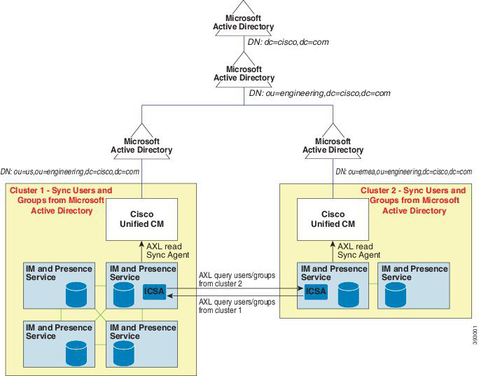

Page 706
Figure 13: Enterprise Groups Deployment Model 2
Enterprise Groups Limitations
Table 60: Enterprise Groups Limitations
Description
Limitation
When a Cisco Jabber user enables the "Block Everyone" feature from
within their Cisco Jabber policy settings, the block prevents other Jabber
users from viewing or exchanging IMs and Presence with the blocking
user, unless they are listed as a contact in the blocking user's contact
list.
For example, a Cisco Jabber user (Andy) has enabled Block everyone
within his personal Jabber settings. The following list breaks down how
Andy's block affects other Jabber users whom may or may not be
included in Andy's personal contact list. In addition to the block, Andy
has a personal contact list that:
• Includes Bob—Because Bob is in Andy's personal contact list, he
can still send IMs and view Andy's presence despite the block.
• Omits Carol—Carol cannot view Andy's presence or send IMs due
to the block..
• Omits Deborah as a personal contact. However, Deborah is a
member of an enterprise group that Andy has listed as a
contact—Deborah is blocked from viewing Andy's presence or
sending IMs to Andy.
Note that Deborah is blocked from viewing Andy's presence, or sending
IMs to Andy, despite the fact that she is a member of an enterprise group
in Andy's contact list. For additional details on enterprise group contacts
behavior, see CSCvg48001.
Block Everyone
Feature Configuration Guide for Cisco Unified Communications Manager, Release 15 and SUs
664
Custom Features
Enterprise Groups Limitations
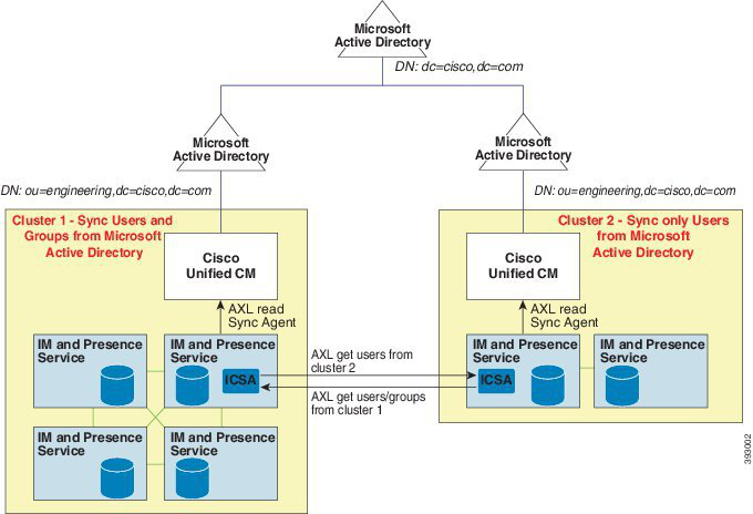
Page 707
Description
Limitation
Enterprise Groups is supported for releases 11.0(1) and higher.
If the synced group includes group members from a 10.x intercluster
peer, users on the higher cluster cannot view the presence of synced
members from the 10.x cluster. This is due to database updates that were
introduced in 11.0(1) for the Enterprise Groups sync. These updates are
not a part of the 10.x releases.
To guarantee that users homed on the higher cluster can view the
presence of group members homed on the 10.x cluster, users on the
higher cluster should manually add the 10.x users to their contact lists.
There are no presence issues for manually added users.
Intercluster peering with a 10.x
cluster
Multilevel grouping is not allowed for the group sync.
Multilevel grouping
When a user group and users are present in the same search base,
group-only synchronization is not allowed. Instead, the user group as
well as the users are synchronized.
Group-only synchronization
You can synchronize a maximum of 15000 user groups from Microsoft
Active Directory server to the Unified Communications Manager
database. Each user group can contain from 1 to 200 users. You can
configure the exact amount on the Cisco Unified CM IM and Presence
Administration > System > Service Parameters window.
The maximum number of user accounts in the database cannot exceed
160,000.
Maximum number of user groups
If a user group is moved from one organization unit to another, you must
perform a full sync on the original unit followed by a full sync on the
new unit.
User group migration
Local groups are not supported. Only groups synchronized from
Microsoft Active Directory are supported.
Local groups
Group members that are not assigned to IM and Presence Service nodes
display in the contact list with the presence bubble greyed out. However,
these members are considered when calculating a maximum numbers
of users allowed in the contact list.
Group members not assigned to IM
and Presence Service nodes
During migration from Microsoft Office Communication Server, the
Enterprise Groups feature is not supported until users are fully migrated
to the IM and Presence Service node.
Migration from Microsoft Office
Communication Server
If you change the synchronization option in the LDAP Directory
Configuration window while the synchronization is in progress, the
existing synchronization remains unaffected. For example, if you change
the synchronization option from Users and Groups to Users Only when
the synchronization is in progress, the users and groups synchronization
still continues.
LDAP synchronization
Feature Configuration Guide for Cisco Unified Communications Manager, Release 15 and SUs
665
Custom Features
Enterprise Groups Limitations
Page 708
Description
Limitation
Group search functionality over the Edge is offered in this release, but
has not been fully tested. As a result, full support for group searches
over the Edge cannot be guaranteed. Full support is expected to be
offered in a future release.
Group search functionality over the
Edge
If a group name or a group member name is updated in the external
LDAP directory, it gets updated on the Cisco Jabber contact list only
after the periodic Cisco Intercluster Sync Agent service synchronization.
Typically, the Cisco Intercluster Sync Agent service synchronization
occurs every 30 minutes.
Cisco Intercluster Sync Agent
service periodic synchronization
If users and user groups are synchronized into the Cisco Unified
Communications Manager database as part of the same synchronization
agreement, the user and group association gets updated as expected in
Cisco Unified Communications Manager database after synchronization.
However, if a user and user group are synchronized as part of different
synchronization agreements, the user and the group may not get
associated in the database after the first synchronization. The user and
group association in the database depends on the sequence in which the
synchronization agreements are processed. If the users are synchronized
ahead of the groups, then the groups may not be available in the database
for association. In such cases, you must ensure that the synchronization
agreement with groups is scheduled ahead of the synchronization
agreement with the users. Otherwise, after the groups synchronize into
the database, the users will get associated with the groups after the next
manual or periodic sync with the sync type set as Users and Groups.
Users and corresponding group info will be mapped only when the
agreement sync type is set as Users and Groups
.
Synchronization of users and user
groups through different
synchronization agreements in
LDAP configuration
Tested Scenario
In a Intercluster deployment with two clusters Cluster A and Cluster B:
Cluster A has 15K OVA and 15K users enabled for IM and Presence
Service out of 160K users that are synced from Active Directory. The
tested and supported average number of enterprise groups per user on
15K OVA cluster is 13 enterprise groups .
Cluster B has 25K OVA and 25K users enabled for IM and Presence
Service out of 160K users that are synced from Active Directory. The
tested and supported average number of enterprise groups per user on
25K OVA is 8 enterprise groups.
The tested and supported sum of user's personal contacts in roster and
the contacts from enterprise groups that are in a user's roster is less than
or equal to 200.
Note
In environments with more than 2 clusters these numbers are not
supported.
Tested OVA information for
Enterprise Groups
Feature Configuration Guide for Cisco Unified Communications Manager, Release 15 and SUs
666
Custom Features
Enterprise Groups Limitations
Page 709
Description
Limitation
When you export the user's contact list using Bulk Administration >
Contact List > Export Contact List, the Contact List CSV file doesn't
include the details of enterprise group they had in Jabber client.
Export Contact List
Feature Configuration Guide for Cisco Unified Communications Manager, Release 15 and SUs
667
Custom Features
Enterprise Groups Limitations
Page 710
Feature Configuration Guide for Cisco Unified Communications Manager, Release 15 and SUs
668
Custom Features
Enterprise Groups Limitations
Page 711
P A R T XIII
Device Management
• Headset and Accessories Management, on page 671
• Headset Services, on page 689
• Native Phone Migration using IVR and Phone Services, on page 697
• Video Endpoints Management, on page 717

Page 712
Page 713
C H A P T E R 55
Headset and Accessories Management
• Headset and Accessories Management Overview, on page 671
• Feature Compatibility for Headset and Accessories Management, on page 671
• Workflow: Configure Headset Serviceability, on page 673
• Headset and Accessories Template Management, on page 678
• Firmware Management, on page 682
• Headset and Accessories Inventory Management, on page 683
• Headset and Accessories Troubleshooting and Diagnostics, on page 687
Headset and Accessories Management Overview
Headset and Accessories Management enhances your Cisco headset deployment, letting administrators manage
headset serviceability from Cisco Unified Communications Manager. From Cisco Unified CM Administration,
administrators can:
• Remotely configure headset settings such as wireless power range, audio bandwidth, and Bluetooth
on/off.
• Define and control the headsets or accessories firmware.
• Get a detailed inventory of all the headsets and accessories in your deployment.
• Diagnose and troubleshoot headsets with Remote PRT, headset metrics in Call Management Records
(CMR), and alarms.
FeatureCompatibilityforHeadsetandAccessoriesManagement
Cisco Headset and Accessories Management is supported in Unified Communications Manager from the
following releases:
• Release 12.5(1)SU4 for 12.x releases
Along with the Unified Communications Manager version, feature support is dependent on the firmware
versions of Cisco Headsets and Accessories, Cisco IP Phone, and Cisco Jabber. The following table lists the
available headset and accessories management features depending on the headset or accessories, phone, and
Unified Communications Manager versions you use.
Feature Configuration Guide for Cisco Unified Communications Manager, Release 15 and SUs
671

Page 714
The Cisco Headset and Accessories Management feature is not supported in 12.0(x) or 12.5(1). For earlier
versions, you may have a limited support for sending headset and accessories configuration templates for IP
phones manually via the defaultheadsetconfig.json configuration file and TFTP. Refer to your
headset Administration Guide for details.
Note
Table 61: Headset Serviceability Features for Cisco IP Phones
Unified
CM
12.5(1)SU1
and
above** +
Phone
Firmware
12.5(1)SR3
Unified
CM 12.5(1)
or earlier
- Phone
Firmware
12.5(1)SR3
Unified
CM
12.5(1)SU1
and
above** +
Phone
Firmware
12.5(1)
Unified
CM 12.5(1)
or earlier
- Phone
Firmware
12.5(1)
Unified
CM
12.5(1)SU1
and
above** +
Phone
Firmware
12.1(1) or
earlier
Unified
CM 12.5(1)
or earlier
- Phone
Firmware
12.1(1) or
earlier
Serviceability Feature
—
X
N/A
X
—
—
Manual Remote Configuration
X
—
—
—
—
—
Headset Firmware Upgrade on
Unified CM
X
—
—
—
—
—
Remote Headset and Accessories
Configuration on Unified CM
X*
—
—
—
—
—
Headset and Accessories inventory
on Unified CM
X
X
—
—
—
—
Configuration Reset on the phone
UI
X*
—
—
—
—
—
Headset Call Management Records
(CMR)
• * This feature is only available on headsets with Headset Firmware 1.5 or later.
• **This feature is not supported in the 12.0.x and 12.5(1) releases.
• N/A When you upgrade to Unified CM 12.5(1) or higher from an earlier version, most Cisco IP Phones
will upgrade automatically to Phone Firmware 12.5(1)SR3 or higher versions.
Feature Configuration Guide for Cisco Unified Communications Manager, Release 15 and SUs
672
Device Management
Feature Compatibility for Headset and Accessories Management

Page 715
Table 62: Headset Serviceability Features for Cisco Jabber
Unified
CM 12.5(1)
and
above** +
Jabber
version
12.6(1)MR
Unified
CM 12.5(1)
or earlier
- Jabber
version
12.6(1)MR
Unified
CM 12.5(1)
and
above** +
Jabber
version
12.6(1)
Unified
CM 12.5(1)
or earlier
- Jabber
version
12.6(1)
Unified
CM
12.5(1)SU1
and
above** +
Jabber
version
12.5(1) or
earlier
Unified
CM 12.5(1)
or earlier
- Jabber
version
12.5(1) or
earlier
Serviceability Feature
X
—
—
—
—
—
Headset Firmware Upgrade through
Unified CM
X
—
X
—
—
—
Remote Headset and Accessories
configuration through Unified CM
X*
—
X*
—
—
—
Headset and Accessories inventory
on Unified CM
X
X
—
—
—
—
Local configuration reset
X
X
X
X
—
—
Local UI configuration
X
X
—
—
—
—
Local Headset and Accessories
version display
• * This feature can only detect headsets with Headset Firmware 1.5 or later.
• **This feature is not supported in the 12.0.x and 12.5(1) releases.
Third-Party Headset and Accessories Support
If you are deploying third-party headsets or accessories, Unified Communications Manager supports headset
and accessories inventory management with limited information for the third-party headsets or accessories
right from the Cisco Unified CM Administration interface. Unified Communications Manager does not support
headset or accessories configuration templates, firmware, diagnostics, and headset CMRs for third-party
headsets.
Workflow: Configure Headset Serviceability
Use the following workflow to guide you through the setup of your Cisco Headset Serviceability feature.
After you complete this workflow, you can configure headset or accessories settings, maintain headset or
accessories latest firmware loads, headset or accessories association to users, enable headset-based Extension
Mobility, and maintain inventory.
Feature Configuration Guide for Cisco Unified Communications Manager, Release 15 and SUs
673
Device Management
Third-Party Headset and Accessories Support
Page 716
Procedure
Purpose
Command or Action
Turn on Cisco Headset Service in Cisco
Unified Serviceability.
Activate Cisco Headset Service, on page 674
Step 1
Make sure you install and upgrade the latest
headset/accessories firmware using a COP file.
Prepare Your Headset COP Files, on page 675
Step 2
If you haven't yet configured User Profiles, use
this procedure to set up profiles for your users.
Configure User Profiles for Headset Users, on
page 676
Step 3
If all User Profiles are configured, you can skip
this task.
Assign User Profiles to your end users. If you've
already assigned User Profiles, you can skip
this task.
Apply User Profiles to End Users, on page 677
Step 4
Configure default settings and firmware for a
Cisco headset and accessories template.
Configure a Headset and Accessories Template,
on page 681
Step 5
Associate User Profiles to the template such
that users whom use that User Profile are
assigned to this headset and accessories
template.
Check that you can see your deployed headset
and accessories inventory through the Cisco
Unified CM interface.
View Headset and Accessories Inventory, on
page 684
Step 6
Activate Cisco Headset Service
Before you can begin administering Cisco Headsets and Accessories through the Cisco Unified CM
Administration interface, turn on Cisco Headset Service in Cisco Unified Communications Manager
Serviceability.
Cisco Headset service should be activated on all the Unified Communications Manager nodes wherever Cisco
CallManager service is already running. Ensure that you activate the Cisco Headset service on the Unified
Communications Manager nodes where you want to administer headsets or accessories using the Cisco Unified
CM Administration interface. The Cisco CallManager service will be automatically activated when you enable
the Cisco Headset service. Deactivate the Cisco CallManager service if you do not need it.
Note
Procedure
Step 1
From Cisco Unified CM Administration, navigate to Cisco Unified Serviceability and click Go.
Step 2
Select Tools > Service Activation.
Feature Configuration Guide for Cisco Unified Communications Manager, Release 15 and SUs
674
Device Management
Activate Cisco Headset Service

Page 717
Step 3
Check the Cisco Headset Service check box from the CM Services section and select Save.
What to do next
Prepare your Headset COP Files.
Prepare Your Headset COP Files
You can install and upgrade the latest headset firmware using a COP file. A headset COP file contains all the
firmware versions of different headset or accessories models along with their configuration data.
Ensure that the Cisco Headset service is up and running before the COP file is installed.
Ensure that the headset COP file is installed on all nodes of Unified Communications Manager.
Note
1.
Install or upgrade the COP file to the Unified Communications Manager system before you can start using
your Cisco headsets or accessories.
When you connect your headset or accessories to the endpoints, the headset and accessories template
configuration changes are applied. If you make any updates to the headset and accessories template
configurations on Unified Communications Manager, the endpoints apply these configuration updates on the
connected headsets or accessories.
All configuration updates depend on the version of the headset and accessories template in the COP file. If
the headset and accessories template version is higher in the latest COP file, the configuration file on Unified
Communications Manager is updated. If the configuration file in the COP file is upgraded, the headset and
accessories template version in Unified Communications Manager is updated irrespective of the version of
the template and vice versa. The following list shows the various template version update scenarios after a
COP file upgrade:
• If the Unified Communications Manager is currently installed with the headset and accessories template
version 1-10 and you upgrade your Unified Communications Manager server that has headset and
accessories template version 1-12, then the chosen headset and accessories template version is 1-12.
Unified Communications Manager opts for the higher headset and accessories template version.
• If the Unified Communications Manager is currently installed with the headset and accessories template
version 1-10 and you upgrade your Unified Communications Manager server that has headset and
accessories template version 1-9, then the chosen headset and accessories template version is 1-10.
Unified Communications Manager opts for the higher headset and accessories template version.
• If the Unified Communications Manager is currently installed with the headset and accessories template
version 1-10 and you install a COP file that has headset and accessories template version 1-12, then the
chosen headset and accessories template version is 1-12. Headset and accessories template installed with
the COP files is the preferred option.
• If the Unified Communications Manager is currently installed with the headset and accessories template
version 1-10 and you install a COP file that has headset and accessories template version 1-9, then the
chosen headset and accessories template version is 1-9. Headset and accessories template installed with
the COP files is the preferred option.
Feature Configuration Guide for Cisco Unified Communications Manager, Release 15 and SUs
675
Device Management
Prepare Your Headset COP Files

Page 718
• If you had a COP file installed that has headset and accessories template version 1-12 and you upgrade
your Unified Communications Manager server having headset and accessories template version 1-10,
then the chosen headset and accessories template version is 1-12. Unified Communications Manager
opts for the higher headset and accessories template version.
Configure User Profiles for Headset Users
If you haven't yet configured User Profiles for your users, use this procedure to set up profiles. Your headset
and accessories templates will be assigned to users via their User Profile. If you've already configured User
Profiles, you can skip this task.
Configure multiple User Profiles for different groups of users as per your deployment needs. By default, all
User Profiles get assigned to the System default headset template. You can assign them to customized templates
when you configure your headset and accessories template.
Note
Procedure
Step 1
From Cisco Unified CM Administration, choose User Management > User Settings > User Profile.
Step 2
Click Add New.
Step 3
Enter a Name and Description for the user profile.
Step 4
Assign a Universal Device Template to apply to users' Desk Phones, Mobile and Desktop Devices, and
Remote Destination/Device Profiles.
Step 5
Assign a Universal Line Template to apply to the phone lines for users in this user profile.
Step 6
If you want the users in this user profile to be able to use the self-provisioning feature to provision their own
phones, do the following:
a)
Check the Allow End User to Provision their own phones check box.
b) In the Limit Provisioning once End User has this many phones field, enter a maximum number of
phones the user is allowed to provision. The maximum is 20.
Step 7
If you want Cisco Jabber users associated with this user profile to be able to use the Mobile and Remote
Access feature, check the Enable Mobile and Remote Access check box.
Note
By default, this check box is selected. When you uncheck this check box, the Jabber Policies section is
disabled and No Service client policy option is selected by default.
Note
This setting is mandatory only for Cisco Jabber users. Non-Jabber users do not need this setting to be able to
use Mobile and Remote Access. The Mobile and Remote Access feature is applicable only for Jabber Mobile
and Remote Access users and not to any other endpoints or clients.
Step 8
Assign the Jabber policies for this user profile. From the Jabber Desktop Client Policy, and Jabber Mobile
Client Policy drop-down list, choose one of the following options:
• No Service—This policy disables access to all Cisco Jabber services.
• IM & Presence only—This policy enables only instant messaging and presence capabilities.
Feature Configuration Guide for Cisco Unified Communications Manager, Release 15 and SUs
676
Device Management
Configure User Profiles for Headset Users

Page 719
• IM & Presence, Voice and Video calls—This policy enables instant messaging, presence, voicemail, and
conferencing capabilities for all users with audio or video devices. This is the default option.
Note
Jabber desktop client includes Cisco Jabber for Windows users and Cisco Jabber for Mac users. Jabber mobile
client includes Cisco Jabber for iPad and iPhone users and Cisco Jabber for Android users.
Step 9
If you want the users in this user profile to set the maximum login time for Extension Mobility or Extension
Mobility Cross Cluster through the Cisco Unified Communications Self Care Portal, check the Allow End
User to set their Extension Mobility maximum login time check box.
Note
By default Allow End User to set their Extension Mobility maximum login time check box is unchecked.
Step 10
Click Save.
Apply User Profiles to End Users
Associate your users to the User Profiles that you've created. The User Profile must be associated with the
end user, and the MAC of the device must be added under the controlled devices to apply the headset and
accessories template configuration changes.
If you've already assigned all users to the appropriate User Profiles, you can skip this task.
Note
Procedure
Step 1
To add a new end user to the Unified Communications Manager database manually, perform the following:
a)
In Cisco Unified CM Administration, choose User Management > End User.
b) Click Add New.
c)
Enter the User ID and Last name.
d) Choose the User Rank from the drop-down list.
e)
Complete the fields in the End User Configuration window. For field descriptions, see the online help.
f)
Click Save.
Step 2
To associate the end user with the device, perform the following:
a)
In Cisco Unified CM Administration, choose Device > Phone.
b) Select the Cisco IP Phone or device.
c)
Under Device Information, select User as the Owner and select the Owner User ID.
d) Click Save and Apply Config for the configuration changes to take effect.
Feature Configuration Guide for Cisco Unified Communications Manager, Release 15 and SUs
677
Device Management
Apply User Profiles to End Users

Page 720
Headset and Accessories Template Management
You can assign headset and accessories templates to user profiles in Cisco Unified Communications Manager
to configure default headset settings for your users. The headset and accessories template provides the option
to associate User Profiles. Unified Communications Manager supports the following types of headset and
accessories templates:
Standard Default Headset Configuration Template
This is the system default template that contains the factory default settings for all headset and accessories
model series. This template contains the headset or accessories settings supported by the latest headset or
accessories firmware installed on your system for all your headset or accessories model series. You cannot
edit the default settings though you can change the profile configuration setting.
The Standard Default Headset Configuration template is created only when the Cisco Headset Service is
activated in the Cisco Unified Serviceability user interface.
Note
By default, all User Profiles are associated to the standard headset template unless the administrator associates
these user profiles to any of the custom defined headset templates. You can make copies of the standard default
headset template to create custom template with customized values of the parameters including the headset
or accessories firmware version.
System Generated Custom Headset Template
For some earlier releases that did not support the full Cisco Headset Serviceability feature, administrators
could configure and deploy headset and accessories templates manually via the
defaultheadsetconfig.json configuration file and TFTP. If you used this method on a previous
release, and then upgrade to this release, the config file is converted to the System Generated Custom
Headset Template and displays in the Headset and Accessories Configuration Template window. Following
the upgrade, users and devices that used the config file are associated to this custom template.
Custom Headset Configuration Template
From Cisco Unified CM Administration, use the Device > Headset and Accessories > Headset and
Accessories Template window to customize headset and accessories templates as per your deployment needs.
You can assign different headset parameters to different models in the same template. You can also assign
different firmware loads to different headset or accessories models. The custom headset or accessories settings
can be assigned to specific sets of users by associating the User Profile(s) to the Custom Headset Template.
Table 63: Headset and Accessories Configuration Template Settings
Description
Field
Headset and Accessories Template Configuration
Enter a unique name to identify the headset and accessories template.
Name
Enter a description that identifies use of the template.
Description
Model and Firmware Settings
Feature Configuration Guide for Cisco Unified Communications Manager, Release 15 and SUs
678
Device Management
Headset and Accessories Template Management

Page 721
Description
Field
Choose any supported headset or accessories model that offers reliable,
high-quality sound for your device.
Choose Model Series
For a standard template, you can view the default pre-defined firmware versions
and settings of the headset or accessories models. You cannot edit the default
values.
For customized templates, click Add to add a new headset or accessories model
and corresponding settings. You cannot add another existing headset or accessories
model in the same template. You can add different headset or accessories models
in a customized template; however, you can only use one firmware per headset
or accessories model. For more information on headset parameters, see the
"Headset Configuration Parameters" table below.
For Standard Default Headset Template Configuration, you can only edit settings
by installing a headset COP file.
Add
Select the required firmware version.
• Remain on current version—Choose this option if you want the headset or
accessories to remain on the existing firmware version (that is, the headset
or accessories firmware version is not upgraded to the latest firmware version
on the system).
• Latest—Choose this option if you want to upgrade the headset or accessories
firmware version to the latest firmware version on the system.
Firmware
For customized templates, click Delete to remove the headset or accessories
model from the headset and accessories template.
Delete
Profile Configuration
Lists the configured User Profiles that are available to use with this headset and
accessories template.
To associate a User Profile to this template, select the profile and click the down
arrow to move the template to Assigned User Profiles.
Note
By default, all User Profiles get assigned to the Standard Default Headset
Configuration Template. To associate a User Profile to a different template,
create the new template and assign the User Profile to the new template.
Available User Profiles
Lists the User Profiles that will use this headset and accessories configuration
template. For users assigned to this profile, the settings in this headset and
accessories configuration template are applied to their Cisco headsets and
accessories during registration.
Click the arrows to add new User Profiles from the Available User Profiles list.
Assigned User Profiles
The following table describes the parameters in each headset and accessories template.
Feature Configuration Guide for Cisco Unified Communications Manager, Release 15 and SUs
679
Device Management
Headset and Accessories Template Management
Page 722
On-premises and multiplatform headset serviceability features are unavailable through an RJ-9 connection.
Note
Table 64: Cisco Headset 500 Series Parameters
Notes
Default
Range
Parameter
Controls the level of sound in the headset. 0 is
very low while 15 is loud.
Configure this setting based on the ambient
noise in the office environment.
7
0 – 15
Speaker Volume
Gain controls how loud the user sounds to other
people on the call. Softer means users sound
quiet while Louder means users sound much
louder.
Configure this setting based on the ambient
noise in the office environment.
Default
Softer – Louder
Microphone Gain
Controls how much of a user's own voice they
can hear through their headset.Off turns off the
sidetone while High means that users receive
much more feedback from their headset
microphones.
Low
Off – High
Sidetone
Controls the Equalizer settings. Warmer settings
mean users hear more bass in their headsets,
while a brighter setting means users hear more
treble.
Default
Warmest – Brightest
Equalizer
Controls the Digital Enhanced cordless
Telecommunications (DECT) codec in the Cisco
Headset 560 Series.
In a dense DECT environment, set the field to
Narrow Band to limit the Cisco Headset 560
Series to the G.727 codec.
Wide
Band
Wide Band, Narrow
Band
Audio Bandwidth
Controls the use of Bluetooth on the Cisco
Headset 560 Series with Multibase. When this
parameter is set to Off, the base deletes all
devices paired with it.
On
On, Off
Bluetooth
Controls the use of the conferencing feature on
the Cisco Headset 560 Series. Conferencing
allows up to three guest headsets to pair with
the same base at once.
See Cisco Headset 500 Series User Guide for
more information on conferencing.
On
On, Off
Conference
Feature Configuration Guide for Cisco Unified Communications Manager, Release 15 and SUs
680
Device Management
Headset and Accessories Template Management

Page 723
Notes
Default
Range
Parameter
Controls the headset's firmware upgrade source.
By default, users can upgrade their headset
through a devices and software connected to
Unified CM or through a cloud-connected
device or software. You can restrict your
headsets to only accept firmware changes
through a Unified CM source.
Allow
from
UCM or
Cisco
Cloud
Allow from UCM or
Cisco Cloud (firmware
will upgrade only),
Restrict to UCM only
(firmware may
upgrade or downgrade)
Firmware Source
Controls the maximum distance between the
Cisco Headset 560 Series and its base.
By default, the bases have a DECT range of
over 330 feet (100 meters) in ideal conditions.
If you configure the DECT radio range to
Medium Range or Short Range, the headset
base consumes less power but users can't move
as far from the base while on a call. Configure
DECT radio range to Short Range for high
density headset deployment.
For more detailed information on DECT
deployment, refer to the white paper on Cisco
Headset deployment, How to Deploy DECT at
Work for the Cisco Headset 560 Series.
Medium
Range
Autorange, Medium
Range, Short Range
DECT Radio Range
Controls how the Cisco Headset 560 Series
behaves if you lift the headset off the base when
you have an incoming call.
On
On, Off
Headset dock behavior
Configure a Headset and Accessories Template
Use this procedure to configure a headset and accessories template with customized settings that you can
apply to Cisco Headsets and Accessories. You can create a customized template or use the system-defined
Standard Default Headset Template.
The Standard Default Headset Configuration Template is a system-defined template. You can assign new
User Profiles to the Standard Default Headset Template but you can't edit the template. By default, all user
profiles are assigned to this template. To disassociate a user profile from this template, you must assign the
profile to a new template.
Note
Procedure
Step 1
From Cisco Unified CM Administration, choose Device > Headset and Accessories > Headset and
Accessories Template.
Step 2
Do either of the following:
Feature Configuration Guide for Cisco Unified Communications Manager, Release 15 and SUs
681
Device Management
Configure a Headset and Accessories Template

Page 724
• To edit an existing template, select the template.
• To create a new template, select any existing template and click Copy. The existing settings are applied
to your new template.
Step 3
Add a Name and Description for the template.
Step 4
Under Model and Firmware Settings, assign any customized headset or accessories settings that you want
to apply to this template. To add a new setting, click the Add button and configure the settings.
Step 5
Use the up and down arrows to move the User Profiles that you want to assign to this template to the Assigned
Uers Profiles list box. All users whom are assigned to those profiles will also be assigned to this headset and
accessories template.
Step 6
Click Save.
Step 7
Use the Set to Default button to return to the default template settings.
Step 8
Click Apply Config.
For a Standard Default Headset Configuration Template, the Apply Config button takes effect for the following:
• Devices owned by users you added to the Assigned User Profile list
• Anonymous devices
For a Customized Headset Configuration Template, the Apply Config button takes effect only for devices
owned by users you added to the Assigned User Profiles list.
Firmware Management
Most phones and devices connected to the Unified Communications Manager support the Cisco Headset 500
Series and Cisco Headset 700 Series. Install the latest phone firmware release and device package before
connecting your headset or accessories to a phone. When the headset or accessories first connects, it downloads
the required firmware and begins the upgrade process.
For a given headset or accessories model, the following two firmware options are supported:
• Remain on current version—Choose this option if you want the headset or accessories to remain on
the existing firmware version (that is, the headset or accessories firmware version is not upgraded to the
latest system firmware version).
• Latest—Choose this option to upgrade or downgrade the headset or accessories. The system installs and
runs the chosen software, even if that firmware is an older release from what the headset or accessories
currently has.
For example, if you choose 1-5-1-10 as the latest, that firmware will be installed on the headset or
accessories regardless of whether the headset or accessories currently has 1-5-1-9 or 1-5-1-11.
Firmware Considerations
• Users assigned to the standard headset template will always receive the latest headset or accessories
firmware and settings.
• Settings shown in the Headset Template Configuration (both Standard and Custom) are always set to the
Latest firmware for all headset and accessories model series.
Feature Configuration Guide for Cisco Unified Communications Manager, Release 15 and SUs
682
Device Management
Firmware Management
Page 725
Headset and Accessories Inventory Management
Cisco IP Phones send headset and accessories inventory data to Unified Communications Manager whenever
the headset and accessories are in a connected or disconnected state. Unified Communications Manager stores
the inventory data so you can generate an Inventory Summary Report or Custom Inventory Report for all
headsets and accessories deployed in this server.
Report information includes: headset or accessories serial and model number, docking station details, firmware,
configuration templates used, vendor details, and headset or accessories connection status to devices.
Headset and Accessories Inventory
From Cisco Unified CM Administration, use the Device > Headset and Accessories > Headset and
Accessories Inventory window to view a full list of all headsets and accessories that are deployed on your
server. You can use this information to generate reports for all deployed headsets and accessories. If you click
the Serial Number of the device, you can view details of individual headsets and accessories in a pop-up
window.
Table 65: Headset and Accessories Inventory Settings
Description
Field
Serial Number of the headsets or accessories. This number is unique for every
individual headset or accessories.
Note
For non-Cisco headsets or accessories, the Device Name is used as the Serial
Number. Using the same non-Cisco headset or accessories with multiple phones
creates duplicate headsets or accessories records.
Note
For information on how to locate the Serial Number for a specific headset or
accessories, see the Headset Administration Guide for that headset or accessories
model.
Serial Number
Model number of the headset or accessories.
Model
Displays vendor details.
Vendor
Indicates the type of headset connection: Wired, DECT Wireless, or Unknown.
Type
Displays the most current firmware load of the headset or accessories.
Firmware
Displays information of the end user using the phone or device.
User
Displays information of the end user using the phone or device. The field is blank
when there are no headsets or accessories associated.
Attached Phone Owner
User ID
Displays the end user information associated with the Serial Number of the headset
or accessories.
Headset/Accessories
Owner
Display the name of the headset or accessories configuration template.
Template
Feature Configuration Guide for Cisco Unified Communications Manager, Release 15 and SUs
683
Device Management
Headset and Accessories Inventory Management
Page 726
Description
Field
Displays the status of the headset or accessories activities. It can be: Connected
or Disconnected.
Status (since)
Displays the type of docking model station.
Dock Model
Name of the device to which the headset or accessories are connected to.
Device Name
Displays the Cisco IP Phone or Cisco Jabber model number. For example,
CP-8865 is a Cisco IP Phone model. CSF is a device type for either Cisco Jabber
for Mac or Cisco Jabber for Windows.
Device Model
Displays the latest version of the software used. It can be a phone firmware or a
Jabber software version.
Software Version
Displays the age of the headset or accessories. If the record is deleted, the headset
or accessories age is reset.
Headset/Accessories Age
(days)
Headset and Accessories Inventory Download
This section is applicable from Release 12.5(1)SU4 and Release 14 onwards.
Important
In Cisco Unified Communications Manager Administration, under Headset and Accessories > Headset and
Accessories Inventory menu path, select Headset and Accessories Inventory Download from the Related
Links drop-down list to download detailed information of the headsets and accessories in the CSV File Format.
You can use this information to analyze data for use cases such as tracking the headsets and accessories usage,
third-party headsets in your deployment, and Refresh headsets.
Headset and Accessories Inventory Management Task Flow
Procedure
Purpose
Command or Action
Lists headsets and accessories deployed on the
server.
View Headset and Accessories Inventory, on
page 684
Step 1
Associates headsets or accessories to the users.
Associate Phone Owner as Headset or
Accessories Owner, on page 685
Step 2
View Headset and Accessories Inventory
You can view a full list of all headsets and accessories deployed on your server. You can use this information
to generate reports for all deployed headsets and accessories.
Feature Configuration Guide for Cisco Unified Communications Manager, Release 15 and SUs
684
Device Management
Headset and Accessories Inventory Management Task Flow

Page 727
Procedure
Step 1
From Cisco Unified CM Administration, choose Device > Headset and Accessories > Headset and
Accessories Inventory.
Step 2
Do either of the following:
• Select Find to see a full list of headsets deployed on your server.
• Enter a one or more search criteria into the search box and select Find.
Associate Phone Owner as Headset or Accessories Owner
Use this procedure to associate bulk headsets or accessories to the user.
Procedure
Step 1
From Cisco Unified CM Administration, choose Device > Headset and Accessories > Headset and
Accessories Inventory.
Step 2
Click Find to view a full list of headsets or accessories deployed on the server.
Step 3
Click Select All or choose the required Serial Numbers and click Associate Phone Owner as
Headset/Accessories Owner to associate headsets or accessories to the user.
Note
You can’t associate headsets or accessories when they are already associated or doesn’t have phone owners
to associate with. The headset or accessories association is visible in the “Headset/Accessories Owner” column
after the page reloads.
You can associate a maximum of only 15 headsets or accessories to a specific user. Once the maximum limit
is reached for a specific user, the remaining headsets or accessories aren’t associated, and an error is displayed.
Step 4
(Optional) Select the required Serial Numbers and click Disassociate Headset /Accessories Owner to
dissociate the headset or accessories serial number from the selected user.
Note
You can’t disassociate headsets or accessories if it’s not associated with the headset or accessories owner.
Step 5
(Optional) To view end user configuration and headset or accessories association details, click the Username
link in the Attached Phone Owner User ID or Headset/Accessories Owner column.
Note
The End User Configuration window displays the headset or accessories association and disassociation
details.
Feature Configuration Guide for Cisco Unified Communications Manager, Release 15 and SUs
685
Device Management
Associate Phone Owner as Headset or Accessories Owner
Page 728
Headset and Accessories Inventory Summary
From Cisco Unified CM Administration, you can use the Device > Headset and Accessories > Headset and
Accessories Inventory Summary window to view an aggregate summary of your deployed headsets and
accessories in the Headset and Accessories Inventory Summary window.
Headset and Accessories Inventory by Model
Description
Field
The headset or accessories model number.
Headset/Accessories
Model
Lists the number of headsets or accessories for each model type in your
deployment.
Note
Click the link in the Quantity column to navigate to the detailed Headset and
Accessories Inventory page, filtered by model type.
Quantity
Headset and Accessories Inventory by Status
Click the hyperlinks in the Headset/Accessories Model, Active, Inactive, or Unassigned columns to navigate
to the detailed Headset and Accessories Inventory page for each status.
Description
Field
The headset or accessories model number.
Headset/Accessories
Model
The headset or accessories has connected within the last 30 days.
Active
The headset or accessories hasn't connected in the last 30 days.
Inactive
The user ID doesn't exist in the system or the inventory record doesn't have a
user ID mapping.
Unassigned
Get an Aggregate Summary of Your Deployed Headsets and Accessories
You can view an aggregate summary of your deployed headsets and accessories in the Headset and Accessories
Inventory Summary window.
Procedure
In Cisco Unified CM Administration, select Device > Headset and Accessories > Headset and Accessories
Inventory Summary.
Feature Configuration Guide for Cisco Unified Communications Manager, Release 15 and SUs
686
Device Management
Headset and Accessories Inventory Summary
Page 729
You can view a breakdown of headset and accessories inventory by model or by headset and accessories
status.
Headset and Accessories Troubleshooting and Diagnostics
You can configure Unified Communications Manager or Cisco Unified Real-Time Monitoring Tool (RTMT)
to collect Problem Report Tool (PRT) logs for headsets or accessories connected to Cisco IP Phones. The
PRT includes data on call quality, codecs used, audio settings, wireless settings, and alert logs.
Unified Communications Manager stores the call diagnostics details for Headsets and Accessories. Cisco IP
Phones send headset or accessories diagnostics data in Headset-Stat header either in a BYE message or a 200
OK response to BYE message to update the CMRs in Unified Communications Manager.
Cisco IP Phones share the headset and accessories diagnostics data with Unified Communications Manager
and this information is stored in the following fields in the CMR record:
• SN—Serial number of the headset or accessories.
• Metrics—Headset and accessories metrics such as RSSI frame errors, connection drop reason, beacon
moves, audio settings, and DECT bandwidth.
For detailed information on how to export and view CMR records, see the Call Reporting and Billing
Administration Guide for Cisco Unified Communications Manager.
Headset CMR records apply to Cisco Headset 500 Series, but not to 700 Series.
Note
Generate PRT for Endpoints on Unified CM
Use this procedure to trigger the Problem Reporting Tool (PRT) on the endpoints.
Procedure
Step 1
From Cisco Unified CM Administration, choose Device > Phone.
Step 2
Click Find and select one or more phones that the headset connects to.
Step 3
Click Generate PRT for Selected to collect PRT logs for the headsets used by the selected phones.
Step 4
Click Save.
Cisco Unified Communications Manager sends SIP Notify messages to remotely trigger the log collection on
the phone and upload it to the log server configured in the “Customer support upload URL” parameter.
Feature Configuration Guide for Cisco Unified Communications Manager, Release 15 and SUs
687
Device Management
Headset and Accessories Troubleshooting and Diagnostics

Page 730
Generate PRT for Endpoints on RTMT
Devices or endpoints generate alarms for each critical event for diagnostics and troubleshooting. These alarms
are generated using the Problem Reporting Tool (PRT) available in the Trace Collection menu or the Device
Monitoring menu of the Cisco Unified Real-Time Monitoring Tool (RTMT) user interface.
Procedure
Step 1
Open the Trace and Log Central options.
Step 2
In the Trace & Log Central tree hierarchy, choose Generate PRT.
The Generate PRT wizard appears.
Step 3
Enter the Device name as configured in the Find and List Phones page in the Cisco Unified CM Administration
user interface.
Step 4
Click Generate PRT.
The generated report is uploaded at the Customer support upload URL. The download option is available
only if the Customer support upload URL parameter is configured at the Enterprise, Profile, or Device level
in the Cisco Unified CM Administration user interface.
Note
Check the Customer support upload URL parameter in the Enterprise, Profile, or Device level configuration
page settings. Else, PRT generation fails.
Feature Configuration Guide for Cisco Unified Communications Manager, Release 15 and SUs
688
Device Management
Generate PRT for Endpoints on RTMT
Page 731
C H A P T E R 56
Headset Services
• Headset Services Overview, on page 689
• Headset Services Prerequisites, on page 690
• Headset Services Administrator Configuration Task Flow, on page 690
• Headset Services End User Association Task Flow, on page 694
Headset Services Overview
Headset Services allow you to connect the Cisco Headset into its supported Devices to provide simple and
integrated user experiences such as Headset-based Extension Mobility and many more in the future.
Headset-based Extension Mobility is the first feature introduced under the Headset Services. When you connect
your Cisco headset to Extension Mobility enabled devices, it provides a seamless login experience for extension
mobility log in and log out.
Headset Services allow the administrator and end user to associate headset(s) from any devices such as a
self-owned device, shared space, and common area device. This association helps in authentications and
creating a customized experience for its users. This feature supports both wired and wireless headsets.
Headset association assigns the user’s identity to the headset. You can log in to the services that need user
identity.
The Unified Communications Manager interface allows the administrator to:
• Associate and disassociate headset to end users along with serial numbers.
• Enable Headset-based Extension Mobility.
• Import and export bulk users to headsets association.
Headset-based Extension Mobility login is not supported for Extension Mobility Cross Cluster (EMCC).
Headset-based Extension Mobility login works for devices supporting Mobile and Remote Access (MRA).
The compatible Phone Firmware version is 14.1(1).
Headset-based Extension Mobility login does not work if the same user ID is controlling both the Headset
and the Phone.
Note
Feature Configuration Guide for Cisco Unified Communications Manager, Release 15 and SUs
689


Page 732
Headset Services Prerequisites
• Make sure that end users are already created in the Unified Communications Manager.
• For Extension Mobility login using the headset, ensure that Extension Mobility is enabled in the user
device. And also, Allow headset for Extension Mobility sign in and sign out option is enabled so that
the user can perform Extension Mobility log in or log out using Cisco headset.
Headset-based Extension Mobility feature supports only the latest firmware of 88XX and 78XX series Cisco
IP Phones.
Note
Headset Services Administrator Configuration Task Flow
The administrator can use the following task to associate headset to users and enable Headset-based Extension
Mobility.
Procedure
Purpose
Command or Action
Specifies how to associate and dissociate the
serial number with a user.
Headset Association to a User, on page 690
Step 1
Optional: Allows the end users to create a
headset association for the devices.
Manage End User Headset Association, on page
691
Step 2
Enables Extension Mobility for headsets from
the Unified Communications Manager.
Enable Headset-based Extension Mobility, on
page 692
Step 3
Enables pinless Extension Mobility login.
Enable Pinless Extension Mobility Login, on
page 692
Step 4
Configures automatic logout timeout settings
for headsets.
Configure Extension Mobility Headset Logout
Timer, on page 693
Step 5
Headset Association to a User
Use this procedure to associate the headset with a user.
Procedure
Step 1
From Cisco Unified CM Administration, choose User Management > End User.
Step 2
Click Find and choose an existing user to whom you want to associate the headset.
Feature Configuration Guide for Cisco Unified Communications Manager, Release 15 and SUs
690
Device Management
Headset Services Prerequisites

Page 733
Step 3
In the Associated Headsets section, enter the serial number of the headset that you want to assign.
Step 4
Click Save.
Step 5
Click (+) if you want to associate more headsets to the selected user.
Note
You can associate a maximum of only 15 headsets to a specific user. The headset serial number is unique for
every individual headset. The same headset can’t be associated with two users. To move the headset association
to a different user, you must first disassociate the headset from the first user.
For information on how to locate the Serial Number for a specific headset, refer to the Headset Administration
Guide for that headset model.
Step 6
(Optional) Click (-) to dissociate the headset serial number for the selected user.
Step 7
Click View Details link to view the inventory details of a headset. For more information, see the Headset
Inventory Settings section in the 'Headset and Accessories Management' chapter to view the headset details.
Manage End User Headset Association
Optional: Use this procedure to configure settings in the Unified Communication Manager to enable end
users to associate headset using the Headset Association menu option on the device screen.
Procedure
Step 1
From Cisco Unified CM Administration, choose System > Enterprise Parameters.
Step 2
In the Enterprise Parameters Configuration section, choose one of the following to associate the end user
headset to the device:
• Choose Prompt user to initiate Headset Association from all devices to display the Headset Association
screen when the headset is connected to the device for the first time. By default, this parameter value is
selected.
• Choose Prompt user to initiate Headset association only from Extension Mobility-enabled devices
for the Headset Association screen to only appear in the Extension Mobility enabled devices.
• Choose Do not prompt user to initiate Headset association from all devices to disable Headset
Association screen on all devices. This setting doesn’t prevent the user from initiating headset association
manually from the device menu.
Note
Any changes in the settings is not applicable to the headsets that are already associated with the end user.
Step 3
Click Save and Apply Config for the configuration changes to take effect.
Tip
Click the parameter name or the question mark (?) icon in the Enterprise Parameter Configuration window
for detailed descriptions.
Feature Configuration Guide for Cisco Unified Communications Manager, Release 15 and SUs
691
Device Management
Manage End User Headset Association
Page 734
Enable Headset-based Extension Mobility
Use this procedure to allow users to log in to Extension mobility from associated headsets.
Before you begin
Ensure that you configure Cisco IP Phones and device profiles to the extension mobility service that headset
users can log in, use, and log out of Extension Mobility using a headset. For more information, see Subscribe
to Extension Mobility, on page 408.
Procedure
Step 1
From Cisco Unified CM Administration, choose System > Service Parameters.
Step 2
From the Server field, choose the node running the Cisco Extension Mobility service.
Step 3
From the Service field, choose Cisco Extension Mobility.
Step 4
In the Headset-based Extension Mobility field, choose one of the following to use an associated headset for
extension mobility login:
• Choose Allow headset for Extension Mobility sign in and sign out to allow the headset user to sign
in with extension mobility. By default, this parameter value is selected.
• Choose Do not Allow headset for Extension Mobility sign in and sign out to restrict the headset user
to sign in with Extension Mobility. If you choose this option, end users don't see the Extension Mobility
login or logout screen when they connect their headsets.
Step 5
Click Save.
Enable Pinless Extension Mobility Login
Use this procedure for pinless Extension Mobility login using a headset associated with a user.
This feature is supported from release 12.5(1)SU3 onwards.
Note
Before you begin
Specify the maximum duration the system waits for user input before automatically signing into the Extension
Mobility profile in the Service Parameter Configuration > Auto login timer after headset connect (seconds)
field.
The specified maximum duration takes effect only when PIN entry for headset-based sign in field is set to
Not Required.
Note
Feature Configuration Guide for Cisco Unified Communications Manager, Release 15 and SUs
692
Device Management
Enable Headset-based Extension Mobility

Page 735
Procedure
Step 1
From Cisco Unified CM Administration, choose System > Service Parameters.
Step 2
From the Server field, choose the node running the Cisco Extension Mobility service.
Step 3
From the Service field, choose Cisco Extension Mobility.
Step 4
In the PIN entry for headset-based sign in field, choose one of the following to enable or disable pinless
Extension Mobility login:
• Choose Required to prompt the user to enter a PIN for Extension Mobility login. By default, this parameter
value is selected.
• Choose Not Required to automatically sign in the user within a minute to Extension Mobility. The user
isn’t prompted to enter PIN details on the Phone UI.
Important
When the user automatically signs out within the set time or manually logged out using wired or wireless
headset, we recommend the user to click Cancel to avoid automatic sign-in within the specified duration.
Step 5
Click Save.
Configure Extension Mobility Headset Logout Timer
Use this procedure to configure the auto-logout timeout settings.
If the Headset-based Extension Mobility service parameter in Service Parameter Configuration window is
set to Do not Allow headset for Extension Mobility sign in and sign out, then configuring auto-logout
timer value has no effect.
Note
Procedure
Step 1
From Cisco Unified CM Administration, choose Service > Service Parameters.
Step 2
From the Server field, choose the node running the Cisco Extension Mobility service.
Step 3
From the Service field, choose Cisco Extension Mobility.
Step 4
In the Auto logout timer after headset disconnect field, enter the maximum duration value that the system
can wait for user input when the headset is disconnected from the device before automatically logging out the
user.
Note
By default, the value is set for 5 minutes. You can set the maximum value to 15 minutes.
Step 5
Click Save.
Feature Configuration Guide for Cisco Unified Communications Manager, Release 15 and SUs
693
Device Management
Configure Extension Mobility Headset Logout Timer

Page 736
Headset Services End User Association Task Flow
The end user can use the following task to associate the headset and use the associated identity to login using
Extension Mobility.
Procedure
Purpose
Command or Action
Creates a headset association to the end user.
Associate a User Headset, on page 694
Step 1
Allows skipping the headset association for the
particular end user.
Skip Headset Association, on page 695
Step 2
Enables customized experience to use an
associated headset for Extension Mobility login.
Extension Mobility Login Using Headset, on
page 695
Step 3
Helps to logout the headset from Extension
Mobility within the default set time.
Logout User from Extension Mobility Using
Headset, on page 696
Step 4
Associate a User Headset
Use this procedure to assign the headset to a user.
Procedure
Step 1
Connect the headset to the Cisco IP Phone.
The Associate headset to user popup screen appears on the IP Phone screen.
The Username is automatically populated if the device is in a shared space or common area or user is associated
with the device. If the device is anonymous, the User ID field is blank and any end user can associate the
headset providing the user credentials.
Step 2
Enter or modify User ID and PIN. Contact the administrator if you don’t know the credentials.
Step 3
Click Submit.
Successful associating of headset message is displayed along with the Username.
If you enter invalid credentials (User ID or PIN) more than three times, the Cisco IP Phone displays an error
message.
If the headset association fails, you can disconnect and connect in the headset to provide valid credentials or
contact the administrator.
Step 4
(Optional) To associate headset manually through Cisco IP Phone, choose Settings > Accessories > Cisco
Headset Setup > Associate User.
Note
Feature Configuration Guide for Cisco Unified Communications Manager, Release 15 and SUs
694
Device Management
Headset Services End User Association Task Flow
Page 737
The Associate User option is greyed out if the headset is disconnected. To enable, connect in the headset to
the device.
Skip Headset Association
Use this procedure to skip associating the headset to a user.
Procedure
Step 1
Connect the headset to the Cisco IP Phone.
Step 2
Click Exit before associating the headset to a user.
Step 3
Click Yes if you don't want to associate the headset.
The headset association screen isn’t prompted on any further connections to the device. If the same headset
is connected to another device, the Associate Headset to User popup screen appears on the Cisco IP Phone
screen and navigates you through the association process.
Extension Mobility Login Using Headset
Use this procedure to log in with Extension Mobility using a headset that has a user associated.
Procedure
Step 1
Connect the headset to the Cisco IP Phone.
Step 2
If the headset isn’t associated, perform the following:
a)
Enter the User ID and PIN to associate the headset with the user.
b) Click Submit.
The login screen displays a success message with the associated User ID and allows the user to sign in
with Extension Mobility.
c)
Click Sign In to complete the Extension Mobility login.
Step 3
If the headset is already associated with the user, perform the following:
a)
Enter the PIN to login with Extension Mobility.
b) Select the required user profile.
c)
Click Submit.
Step 4
If a user is already logged in to Extension Mobility on the device and another user plugs in a previously
associated headset, the logout screen appears and allows the user to sign out previously logged in user.
Step 5
Click Yes to log out of the earlier profile.
Step 6
Enter the PIN to login with Extension Mobility.
Step 7
Click Submit.
Feature Configuration Guide for Cisco Unified Communications Manager, Release 15 and SUs
695
Device Management
Skip Headset Association
Page 738
Note
The phone resets each time the device profile changes, and the user profile is changed to the original profile.
Logout User from Extension Mobility Using Headset
Use this procedure to sign out the headset from the Extension Mobility enabled device.
Procedure
Step 1
Disconnect the headset from the Cisco IP Phone.
Step 2
Click Sign Out.
Note
The phone resets and the device profile is changed to the original device profile.
If you disconnect the headset during an ongoing call (one to one call or conference call), the call is not
terminated, and the Extension Mobility sign out occurs only when the call ends.
You are automatically signed out within the set time if you haven’t manually logged out or go out of range
for a wireless headset. By default, the set time is 5 minutes. For more information, see the Configure Extension
Mobility Headset Logout Timer, on page 693 section.
Step 3
Click Cancel if you want to retain the current Extension Mobility session. Reconnect within the default set
time to retain the user profile and avoid a reset.
Feature Configuration Guide for Cisco Unified Communications Manager, Release 15 and SUs
696
Device Management
Logout User from Extension Mobility Using Headset
Page 739
C H A P T E R 57
Native Phone Migration using IVR and Phone
Services
• Native Phone Migration using IVR and Phone Services Overview, on page 697
• Phone Migration Prerequisites, on page 700
• Phone Migration Task Flow Using Self-Provisioning IVR, on page 701
• Phone Migration Task Flow Using Phone Migration Service, on page 706
• View Phone Migration Report, on page 711
• Migrate Phones using Cisco Unified CM Administration Interface, on page 711
• Migration Scenarios , on page 712
NativePhoneMigrationusingIVRandPhoneServicesOverview
The Phone Migration feature is an easy and intuitive Cisco IP Phone migration solution native to Unified
Communications Manager. It minimizes the cost and complexity of replacing deprecated or faulty phones.
Using the solution, an end user or an administrator can easily migrate all the settings from an old phone to a
new phone with a simple user interface. Solution supports following methods for migrating the phones:
• Using Self-provisioning IVR Service
• Using Phone Migration Service
• Using Cisco Unified CM Administration Interface
Following table provides a quick comparison of the various phone migration options:
Table 66: Different Phone Migration Options and Considerations
Using Unified CM
Administration Interface
Using Phone Migration
Service
Using Self-provisioning
IVR Service
Administrator
End user (Self-service)
End user (Self-service)
End user or
administrator driven
phone migration
No
No
Yes
Auto-registration
required
Feature Configuration Guide for Cisco Unified Communications Manager, Release 15 and SUs
697

Page 740
Using Unified CM
Administration Interface
Using Phone Migration
Service
Using Self-provisioning
IVR Service
• Sign in to Cisco
Unified CM
Administration
interface
• Choose “Migrate
Phone” option in the
Phone Configuration
page of the old
phone
• Enter phone type
(model & protocol)
and MAC address of
the new phone
• Plug-in new phone to
the network
• Key in primary
extension and PIN
(optional)
• Auto register a new
phone
• Dial
self-provisioning
IVR number
• Follow the voice
prompts
Migration steps
High
Low
Medium
Administrator
involvement
While phone migration using Self-provisioning IVR Service and Phone Migration Service facilitates the
migration of the phone by an end user as a self-service; administrators, can use these methods to migrate the
phone on-behalf of an end-user or common phones (for example, a lobby phone).
Note
During phone migration, if the end user does not remember the PIN, administrators should advise the end
user to log in to the Self Care Portal to change the PIN, if required.
Note
Enterprise Parameters for Phone Migration
Migration depends on the following two parameters in the Enterprise Parameters Configuration page:
• When Provisioning a Replacement Phone for an End User—You can choose either Retain Existing
Phone(s) (default option) or Delete the Existing Phone for that End User. If the Retain Existing
Phone(s) option is selected, then during migration the old phone is marked as migrated and can be filtered
in the Find and List Phones page to generate migration report.
If the administrator decides to choose the Retain Existing Phone(s) option for
phone migration, a total of two licenses will be consumed, that is, one license
each for the existing phone and the new phone picked up for migration.
Note
Feature Configuration Guide for Cisco Unified Communications Manager, Release 15 and SUs
698
Device Management
Enterprise Parameters for Phone Migration

Page 741
During phone migration, if the administrator decides to choose the Retain Existing
Phone(s) option for phone migration, the intercom DN is not migrated to the new
device. If the Delete the Existing Phone for that End User option is selected,
the intercom DN information is also migrated.
Note
• Security Profile for Migrated Phone—This option determines the type of security profile that is applied
for a migrated phone (old phone was in secure mode) during phone migration. Choosing the Non-secure
profile brings up your device in the non-secure mode.
• Phone Migration User Identification Prompt—This parameter determines whether a user is able to
proceed with phone migration using the Self-Service User ID or using the Primary Extension. If the Use
Enduser Self-Service User ID option is selected, the end user is prompted to enter the unique Self-Service
User ID before proceeding with phone migration. If the Use Enduser Primary Extension option is
selected, you can migrate your phone after entering the primary extension number. In this mode, if the
same DN exists in different route partitions, phone migration is not possible using IVR or Phone Migration
service.
The default value is Use Enduser Primary Extension.
To facilitate secure phone migration, the following Standard Universal Phone Security Profiles templates
have been added. Based on the old phone security profile, the new phone chooses one of these new profiles.
• Universal Device Template - Security Profile - Non-Secure
• Universal Device Template - Security Profile – Authenticated
• Universal Device Template - Security Profile – Encrypted
• Universal Device Template - Security Profile - Encrypted - Device_TFTP
• Universal Device Template - Security Profile - Encrypted EC preferred
The following table lists the new devices security profile mappings after phone migration:
Table 67: Phone Security Profile Migration Data
New Mapped
Profile Name
Old Security Profile Settings
Key Order
Transport Type
TFTP Encrypted
Configuration
Device Security
Mode
Universal Device
Template - Security
Profile - Non-Secure
RSA
TCP
No
Non-Secure
Universal Device
Template - Security
Profile –
Authenticated
RSA
TLS
No
Authenticated
Feature Configuration Guide for Cisco Unified Communications Manager, Release 15 and SUs
699
Device Management
Enterprise Parameters for Phone Migration

Page 742
New Mapped
Profile Name
Old Security Profile Settings
Universal Device
Template - Security
Profile – Encrypted
RSA
TLS
No
Encrypted
Universal Device
Template - Security
Profile - Encrypted
- Device_TFTP
RSA
TLS
Yes
Encrypted
Universal Device
Template - Security
Profile - Encrypted
- Device_TFTP
EC preferred, RSA
backup
TLS
Yes
Encrypted
Universal Device
Template - Security
Profile - Encrypted
EC preferred
EC preferred, RSA
backup
TLS
No
Encrypted
Phone Migration Prerequisites
Using Self-provisioning IVR
Before your end users can use self-provisioning for migration, the following should be configured:
• Enable Auto-registration.
• End users must have a primary extension. Ensure that the primary DN is always Line 1 on the phone or
device.
• End users must be associated to a user profile or feature group template that includes a universal line
template, universal device template and which has Self-Provisioning enabled.
• Ensure that the right “CTI Route Point” and “Application User” configurations are selected.
• Enable Self-Provisioning IVR service.
Using Phone Migration Service
Before your end users can use Phone Migration Service for migration, the following should be configured:
• Disable Auto-registration.
• End users must have a primary extension. Ensure that the primary DN is always Line 1 on the phone or
device.
• Supported Phone Models: 88XX, 78XX, 8832, and 7832.
• Minimum supported phone version is Release 12.8.1 and above.
Feature Configuration Guide for Cisco Unified Communications Manager, Release 15 and SUs
700
Device Management
Phone Migration Prerequisites
Page 743
Phone Migration Task Flow Using Self-Provisioning IVR
Use the following task flow to guide you through the phone migration procedures.
After you complete this workflow, you can configure Self-Provisioning IVR service, migrate old or faulty
Cisco IP Phones, and track the migrated phones list.
Procedure
Purpose
Command or Action
Activate the Self-Provisioning IVR and CTI
Manager services in Cisco Unified
Serviceability.
Activate Services for Self-Provisioning, on page
701
Step 1
Enable autoregistration parameter for
self-provisioning.
Enable Autoregistration for Self-Provisioning,
on page 702
Step 2
Configure a CTI route point to handle the
self-provisioning IVR service.
Configure CTI Route Point, on page 702
Step 3
Configure the extension that users dial in order
to access the self-provisioning IVR and
associate that extension to the CTI route point.
Assign a Directory Number to the CTI Route
Point, on page 703
Step 4
Configure an application user for the
self-provisioning IVR. Associate the CTI route
point to the application user.
Configure Application User for
Self-Provisioning, on page 703
Step 5
Configure Self-Provisioning system settings.
Configure the System for Self-Provisioning, on
page 704
Step 6
Enables the users to Self-Provision phones in
the user profile to which they are assigned.
Enable Self-Provisioning in a User Profile, on
page 705
Step 7
Choose the migration procedure that applies for
you. The Self-Provisioning IVR can be used by
Migrate phones using any of these procedures:
Step 8
• Migrate Phones Using Self-Provisioning
IVR (Administrator), on page 705
either administrators or phone users to migrate
phones.
• Migrate Phones Using Self-Provisioning
IVR (Phone Users), on page 706
Following the migration, view a report that
shows Cisco IP Phones that are migrated.
View Phone Migration Report, on page 711
Step 9
Activate Services for Self-Provisioning
Use this procedure to activate the services that support the Self-Provisioning feature. Ensure that both the
Self-Provisioning IVR and Cisco CTI Manager services are running.
Feature Configuration Guide for Cisco Unified Communications Manager, Release 15 and SUs
701
Device Management
Phone Migration Task Flow Using Self-Provisioning IVR
Page 744
Procedure
Step 1
From Cisco Unified Serviceability, choose Tools > Service Activation.
Step 2
From the Server drop-down list, select the publisher node and click Go.
Step 3
Under CM Services, check Cisco CTI Manager.
Step 4
Under CTI Services, check Self Provisioning IVR.
Step 5
Click Save.
Enable Autoregistration for Self-Provisioning
Use this procedure for self-provisioning, you must configure the auto-registration parameters on the publisher.
Procedure
Step 1
In Cisco Unified CM Administration, choose System > Cisco Unified CM.
Step 2
Click on the publisher node.
Step 3
Select the Universal Device Template that you want to be applied to provisioned phones.
Step 4
Select the Universal Line Template that you want to be applied to the phone lines for provisioned phones.
Step 5
Use the Starting Directory Number and Ending Directory Number fields to enter a range of directory
numbers to apply to provisioned phones.
Step 6
Uncheck the Auto-registration Disabled on the Cisco Unified Communications Manager check box.
Step 7
Confirm the ports that will be used for SIP registrations. In most cases, there is no need to change the ports
from their default settings.
Step 8
Click Save.
Configure CTI Route Point
Us this procedure to configure a CTI Route Point for the Self-Provisioning IVR.
Procedure
Step 1
From Cisco Unified CM Administration, choose, Device > CTI Route Points.
Step 2
Complete either of the following steps:
a)
Click Find and select an existing CTI route point.
b) Click Add New to create a new CTI route point.
Step 3
In the Device Name field, enter a unique name to identify the route point.
Step 4
From the Device Pool drop-down list, select the device pool that specifies the properties for this device.
Feature Configuration Guide for Cisco Unified Communications Manager, Release 15 and SUs
702
Device Management
Enable Autoregistration for Self-Provisioning
Page 745
Step 5
From the Location drop-down list, select the appropriate location for this CTI route point.
Step 6
From the Use Trusted Relay Point drop-down list, enable or disable whether Unified Communications
Manager inserts a trusted relay point (TRP) device with this media endpoint. The default setting is to use the
Common Device Configuration setting that is associated to this device.
Step 7
Complete the remaining fields in the CTI Route Point Configuration window. For more information on the
fields and their settings, see the online help.
Step 8
Click Save.
Assign a Directory Number to the CTI Route Point
Use this procedure to set up the extension that users will dial in to access the self-provisioning IVR. You must
associate this extension to the CTI route point that you want to use for self-provisioning.
Procedure
Step 1
From Cisco Unified CM Administration, choose Device > CTI Route Point.
Step 2
Click Find and select the CTI route point that you set up for self-provisioning.
Step 3
Under Association click Line [1] - Add a new DN.
The Directory Number Configuration window displays.
Step 4
In the Directory Number field, enter the extension that you want users to dial to access the Self-Provisioning
IVR service.
Step 5
Click Save.
Step 6
Complete the remaining fields in the Directory Number Configuration window. For more information with
the fields and their settings, see the online help.
Step 7
Click Save.
Configure Application User for Self-Provisioning
You must set up an application user for the self-provisioning IVR and associate the CTI route point that you
created to the application user.
Procedure
Step 1
From Cisco Unified CM Administration, choose User > Application User.
Step 2
Perform either of the following steps:
a)
To select an existing application user, click Find and select the application user.
b) To create a new application user, click Add New.
Step 3
In the User ID text box, enter a unique ID for the application user.
Step 4
Select a BLF Presence Group for the application user.
Feature Configuration Guide for Cisco Unified Communications Manager, Release 15 and SUs
703
Device Management
Assign a Directory Number to the CTI Route Point
Page 746
Step 5
Associate the CTI route point that you created to the application user by performing the following steps:
a)
If the CTI route point that you created does not appear in the Available Devices list box, click Find More
Route Points.
The CTI route point that you created displays as an available device.
b) In the Available Devices list, select the CTI route point that you created for self-provisioning and click
the down arrow.
The CTI route point displays in the Controlled Devices list.
Step 6
Complete the remaining fields in the Application User Configuration window. For help with the fields and
their settings, see the online help.
Step 7
Click Save.
Configure the System for Self-Provisioning
Use this procedure to configure your system for self-provisioning. Self-provisioning provides users in your
network with the ability to add their own desk phone through an IVR system, without contacting an
administrator.
In order to use the self-provisioning feature, your end users must also have the feature enabled in their user
profiles.
Note
Procedure
Step 1
From Cisco Unified CM Administration, choose User Management > Self-Provisioning.
Step 2
Configure whether you want the self-provisioning IVR to authenticate end users by clicking one of the
following radio buttons:
• Require Authentication—In order to use the self-provisioning IVR, end users must enter their password,
PIN, or a system authentication code.
• No Authentication Required—End users can access the self-provisioning IVR without authenticating.
Step 3
If the self-provisioning IVR is configured to require authentication, click one of the following radio buttons
to configure the method whereby the IVR authenticates end users:
• Allow authentication for end users only—End users must enter their password or PIN.
• Allow authentication for users (via Password/PIN) and Administrators (via Authentication
Code)—End Users must enter an authentication code. If you choose this option, configure the
authentication code by entering an integer between 0 and 20 digits in the Authentication Code text box.
Step 4
In the IVR Settings list boxes, use the arrows to select the Language that you prefer to use for IVR prompts.
The list of available languages depends on the language packs that you have installed on your system. Refer
to the Downloads section of cisco.com if you want to download additional language packs.
Step 5
From the CTI Route Points drop-down list, choose the CTI route point that you have configured for your
self-provisioning IVR.
Feature Configuration Guide for Cisco Unified Communications Manager, Release 15 and SUs
704
Device Management
Configure the System for Self-Provisioning

Page 747
Step 6
From the Application User drop-down list, choose the application user that you have configured for
self-provisioning.
Step 7
Click Save.
Enable Self-Provisioning in a User Profile
In order for users to be able to Self-Provision phones, the feature must be enabled in the user profile to which
they are assigned.
If you don’t know which user profile your users are using, you can open a user’s settings in the End User
Configuration window and view the User Profile field to get the correct profile.
Note
Procedure
Step 1
From Cisco Unified CM Administration, choose User Management > User Settings > User Profile.
Step 2
Click Find and select the user profile to which the user is assigned.
Step 3
Assign Universal Line Templates and Universal Device Templates to the user profile.
Step 4
Configure user settings for Self-Provisioning:
• Check the Allow End User to Provision their own phones check box.
• Enter a limit for the number of phones a user can provision. The default is 10.
• If you want users to be able to use self-provisioning to reassign a previously assigned phone, check the
Allow Provisioning of a phone that is already assigned to a different End User setting in the user
profile page associated with the end user of old device. Users can reassign a previously assigned phone
only if this check box is enabled in the User Profile that is associated to the old device.
Step 5
Click Save.
Phone Migration Tasks
After self-provisioning Authentication is setup, use any of the following procedures to migrate phones.
Migrate Phones Using Self-Provisioning IVR (Administrator)
Administrators can use this procedure to migrate Cisco IP Phones on behalf of an end user, or to migrate
common phones (for example, a lobby phone).
Before you begin
Make sure that the old phone is in the "Unregistered" state before you proceed with migration. You can plug
the new phone into the network, wait until the phone registers and then perform the migration tasks. Once the
migration is successful, the device will re-register with the users phone configuration data.
Feature Configuration Guide for Cisco Unified Communications Manager, Release 15 and SUs
705
Device Management
Enable Self-Provisioning in a User Profile

Page 748
Procedure
Step 1
Dial the extension that is assigned to the Self-Provisioning IVR from a new phone.
Step 2
Press 2 to replace an existing phone.
Step 3
Enter the primary extension number of an end user phone or common phone followed by the pound key (#).
Step 4
Enter the Authentication Code followed by the pound key (#).
Migration starts after a successful authentication. Following the migration, the phone restarts with configuration
settings migrated from end user’s old phone.
Migrate Phones Using Self-Provisioning IVR (Phone Users)
Phone users can use this procedure to migrate to a new Cisco IP Phone.
Before you begin
Make sure that the old phone is in the "Unregistered" state before you proceed with migration. You can plug
the new phone into the network, wait until the phone registers and then perform the migration tasks. Once the
migration is successful, the device will re-register with the users phone configuration data.
Procedure
Step 1
Dial the extension that is assigned to the Self-Provisioning IVR from a new Cisco IP Phone.
Step 2
Press 2 to replace an existing phone.
Step 3
Enter the primary extension number of your phone followed by the pound key (#).
Step 4
Enter your PIN followed by the pound key (#).
Migration starts after a successful authentication. After successful migration, the phone restarts with the
configuration settings migrated from your old phone.
Note
If the phone is assigned to another user, a phone user can re-provision the phone provided an administrator
has enabled the Allow Provisioning of a phone already assigned to a different End User option in the
user's User Profile window. Talk to your administrator about this option.
Phone Migration Task Flow Using Phone Migration Service
Use the following task flow to guide you through the phone migration procedure using Phone Migration
Service.
After you complete this workflow, you can migrate old or faulty Cisco IP Phones, and track the migrated
phones list.
Feature Configuration Guide for Cisco Unified Communications Manager, Release 15 and SUs
706
Device Management
Migrate Phones Using Self-Provisioning IVR (Phone Users)
Page 749
Procedure
Purpose
Command or Action
Disable the autoregistration parameter before
phone migration.
Disable Autoregistration, on page 707
Step 1
Configure the default phone load before the
phone migration service.
Set Up Default Phone Load, on page 707
Step 2
Configure the required Self-Provisioning
authentication settings.
Configure Self-Provisioning Authentication, on
page 708
Step 3
Choose the migration procedure that applies for
you. The Phone Migration Service can be used
Migrate phones using any of these procedures:
Step 4
• Migrate Phones Using Phone Migration
Service (Administrator), on page 708
by either administrators or phone users to
migrate phones.
• Migrate Phones Using Phone Migration
Service (Phone Users), on page 709
Following the migration, view a report that
shows Cisco IP Phones that are migrated.
View Phone Migration Report, on page 711
Step 5
Disable Autoregistration
To use the Phone Migration Service, autoregistration must be disabled.
Procedure
Step 1
In Cisco Unified CM Administration, choose System > Cisco Unified CM.
Step 2
Click on the publisher node.
Step 3
Check the Auto-registration Disabled on the Cisco Unified Communications Manager check box.
Step 4
Confirm the ports that will be used for SIP registrations. In most cases, there is no need to change the ports
from their default settings.
Step 5
Click Save.
Set Up Default Phone Load
Use this procedure to set up the default phone load before the phone migration service.
Procedure
Step 1
From Cisco Unified CM Administration, choose Device > Device Settings > Device Defaults.
Step 2
Select the required phone model for migration.
Feature Configuration Guide for Cisco Unified Communications Manager, Release 15 and SUs
707
Device Management
Disable Autoregistration
Page 750
Step 3
Enter the phone load and click the Swap Loads button in the phone load to make it the default phone load.
Step 4
Click Save.
Configure Self-Provisioning Authentication
The Phone Migration Service uses Self-Provisioning system settings to authenticate users prior to phone
migration.
Procedure
Step 1
From Cisco Unified CM Administration, choose User Management > Self-Provisioning.
Step 2
Configure whether you want the self-provisioning to authenticate end users by clicking one of the following
radio buttons:
• Require Authentication—In order to use self-provisioning, end users must enter their password, PIN,
or a system authentication code.
• No Authentication Required—End users can access the self-provisioning options without authenticating.
Step 3
If the self-provisioning functionality is configured to require authentication, click one of the following radio
buttons to configure the method whereby the self-provisioning options authenticates end users:
• Allow authentication for end users only—End users must enter their password or PIN.
• Allow authentication for users (via Password/PIN) and Administrators (via Authentication
Code)—End Users must enter an authentication code. If you choose this option, configure the
authentication code by entering an integer between 0 and 20 digits in the Authentication Code text box.
Step 4
Click Save.
Phone Migration Tasks
After self-provisioning Authentication is setup, use any of the following procedures to migrate phones.
Migrate Phones Using Phone Migration Service (Administrator)
Administrators can use this procedure to migrate Cisco IP Phones on behalf of an end user, or to migrate
common phones (for example, a lobby phone).
Before you begin
Make sure that the old phone is in the "Unregistered" state before you proceed with migration. You can plug
the new phone into the network, wait until you get the phone migration or provisioning prompt and start the
migration process. Once the migration is successful, the device re-registers with the users phone configuration
data.
Feature Configuration Guide for Cisco Unified Communications Manager, Release 15 and SUs
708
Device Management
Configure Self-Provisioning Authentication
Page 751
Procedure
Step 1
Connect the new Cisco IP Phone to the network.
Step 2
Select option 2 to replace an existing phone.
Note
If Administrator has not configured Activation Code based device onboarding or phone migration is done on
the 11.5(1)SU8 version of Unified Communications Manager which does not support activation code, the
phone displays the screen to enter the primary extension.
Step 3
Enter the primary extension number of your phone.
Step 4
Enter the Authentication Code.
Migration starts after a successful authentication. After successful migration, the phone restarts with
configuration settings migrated from your old phone.
Note
Consider a scenario where the On-premise Onboarding Method option is selected as Auto registration in
the Device Defaults Configuration page. While performing the phone migration, if you press either the EXIT
or BACK button when an error message is displayed, it takes you directly to the initial phone migration screen
after a possible expected delay. This delay is due to the phones trying to re-register to the Unified CM as
auto-registration is disabled in the Unified Communications Manager server.
Note
If there are more than one device for the user with the same primary extension, user will be prompted to choose
the device to be migrated. For more information, see Phone Migration Service—User Assigned with Multiple
Devices, on page 712.
Migrate Phones Using Phone Migration Service (Phone Users)
Phone users can use this procedure to migrate to a new Cisco IP Phone using a non-IVR method. After you
plug in the phones to the network, the phone will attempt to boot and configure itself. From the default phone
load, users get options to select either the 'Provision a new phone' or 'Replace an existing phone'.
An end user should perform migration only if they are the owner of the old device.
Note
If you decide to choose the Retain Existing Phone(s)' option from the When Provisioning a Replacement
Phone for an End User enterprise parameter and you migrate the phone using the Phone Template, the old
migrated phone configurations details will not be listed in the Find List page. Only the successful new phone
migration details are listed. This is because the Retain Existing Phone(s) option is applicable only for Phone
Migrations based on Phone Types and not based on the Phone Template.
Note
Feature Configuration Guide for Cisco Unified Communications Manager, Release 15 and SUs
709
Device Management
Migrate Phones Using Phone Migration Service (Phone Users)

Page 752
Before you begin
Make sure that the old phone is in the "Unregistered" state before you proceed with migration. You can plug
the new phone into the network, wait until you get the phone migration or provisioning prompt and start the
migration process. Once the migration is successful, the device re-registers with the users phone configuration
data.
Procedure
Step 1
Connect the new Cisco IP Phone to the network.
Step 2
Select the option 2 to replace an existing phone.
Note
If the Administrator hasn't configured Activation Code based device onboarding or phone migration is done
on the 11.5(1)SU8 version of Unified Communications Manager which doesn't support activation code, the
phone displays the screen to enter the primary extension.
Step 3
Enter the primary extension number of your phone.
Step 4
Enter your PIN.
Migration starts after a successful authentication. After successful migration, the phone restarts with
configuration settings migrated from your old phone.
Note
Consider a scenario where the On-premise Onboarding Method option is selected as Auto registration in
the Device Defaults Configuration page. While performing the phone migration, if you press either the EXIT
or BACK button when an error message is displayed, it takes you directly to the initial phone migration screen
after a possible expected delay. This delay is due to the phones trying to re-register to the Unified CM as
auto-registration is disabled in the Unified Communications Manager server.
Note
If there are more than one device for the user with the same primary extension, the user will be prompted to
choose the device to be migrated. For more information, see Phone Migration Service—User Assigned with
Multiple Devices, on page 712.
Phone Migration Service COP File
If you are running any version of the Unified Communications Manager starting from 11.5(1) until 11.5(1)SU7,
install Phone Migration Service COP file (ciscocm-migration-service-11-5-1.zip) to get the Native Phone
Migration feature support.
As part of the COP file installation, ‘Tftp restart’ service is done automatically for Unified Communications
Manager.
If you plan to upgrade the Unified CM after Phone Migration Service COP file installation, ensure that you
upgrade your Unified CM server to a release version that has native support for the Native Phone Migration
feature.
Note
Feature Configuration Guide for Cisco Unified Communications Manager, Release 15 and SUs
710
Device Management
Phone Migration Service COP File

Page 753
View Phone Migration Report
Use this procedure to view the list of all the Cisco IP Phones that are migrated.
Procedure
Step 1
In Cisco Unified CM Administration, select Device> Phone.
Step 2
From the Find and List Phones page, choose Migrate (old phone) from the Find Phone where drop-down
list.
Step 3
Click Find.
You can view the list of all the old devices that got migrated. This list is populated only if the Retain Existing
Phone option is configured in the Enterprise Parameters page.
MigratePhonesusingCiscoUnifiedCMAdministrationInterface
Use this procedure to migrate phones using either the Phone Template or Phone Type (and Protocol) options
in the Cisco Unified CM Administration interface.
Procedure
Step 1
In the Find and List Phones window (Device > Phone), find the Cisco IP Phone that you want to migrate.
Step 2
In the Phone Configuration window for the Cisco IP Phone that you want to migrate, choose Migrate Phone
from the Related Links drop-down list.
Step 3
To migrate phones, you can use one of the following options:
a)
Phone Template—Choose the phone template for the phone model to which you want to migrate the
phone configuration.
b) Phone Type (and Protocol)—Choose the Cisco IP Phone model for which you want to migrate the phone
configuration.
Step 4
Enter the MAC address for the new Cisco Unified IP Phone to which you are migrating the configuration.
Step 5
(Optional) Enter a description for the new phone. For more information on the migration considerations and
configuration settings, see the Cisco Unified CM Administration Online Help pages.
Step 6
Click Save.
If a warning message displays that the new phone may lose feature functionality, click OK. After migration,
the new device will inherit setting of the old phone.
Feature Configuration Guide for Cisco Unified Communications Manager, Release 15 and SUs
711
Device Management
View Phone Migration Report
Page 754
Migration Scenarios
Phones Using Shared Lines
Consider a scenario where an old phone has the primary DN shared line with multiple devices. These devices
may be owned by the same user or among multiple users. When you try to migrate the old phone with a new
Cisco IP Phone using Self-Provisioning IVR or Phone Migration Service methods using a shared line, migration
is possible only for users who own the device with the DN as Line 1. Here, the shared lines feature settings
are carried over after phone migration.
If the old phone does not support the Shared Line feature, the old phones lines are removed after phone
migration. The new phone retains the old phones lines after phone migration.
Phone Migration Service Running on Proxy TFTP
Native phone migration using Phone Migration Service support Cisco proxy TFTP server deployment models.
Phone Migration Service running on the proxy TFTP searches for the primary extension on all the remote
clusters and redirect the phone to its home or local Phone Migration Service for completing phone migration.
In a proxy setup environment, Unified Communications Manager server looks for devices with same DN in
a remote cluster. If there is more than one device in the registered or unregistered state with the same DN in
any one of the off-cluster, those devices from that particular off-cluster is not considered for phone migration.
This is a known limitation for Release 11.5(1)SU8.
In Proxy TFTP, after migration, the phone restarts with configuration settings migrated from your old phone.
Note that the phone takes 2 reset cycles to restart after successful migration.
Note
Phone Migration Service—User Assigned with Multiple Devices
If there is more than one device for the user with the same primary extension for migration, user will be
prompted to choose the device to be migrated.
The following table displays the various migration scenarios possible:
Table 68: Device Listing and Migration Scenarios
Phone Display During Migration
Device Status Before Phone
Migration
Phone Configuration settings of
Device 2 will be migrated.
Device 1—Registered
Device 2—Unregistered
Scenario 1
Phone Configuration settings of
Device 3 will be migrated.
Device 1—Registered
Device 2—Registered
Device 3—Unregistered
Scenario 2
Feature Configuration Guide for Cisco Unified Communications Manager, Release 15 and SUs
712
Device Management
Migration Scenarios

Page 755
Phone Display During Migration
Device Status Before Phone
Migration
Displays the device list with the
following: Description, Phone
Model, and MAC Address. Users
should choose the device from the
list required for phone migration.
Device 1—Registered
Device 2—Unregistered
Device 3—Unregistered
Scenario 3
Displays the device list with the
following: Description, Phone
Model, and MAC Address. Users
should choose the device from the
list required for phone migration.
Device 1—Unregistered
Device 2—Unregistered
Device 3—Unregistered
Scenario 4
Displays the device list with the
following: Description, Phone
Model, and MAC Address. Users
should choose the device from the
list required for phone migration.
Device 1—Registered
Device 2—Registered
Device 3—Registered
Scenario 5
Displays the device list with the
following: Description, Phone
Model, and MAC Address. Users
should choose the device from the
list required for phone migration.
More than 3 devices are in
Registered or Unregistered states
Scenario 6
Device Display Based on Unified CM Parameter Settings
The following table lists the behavior of the migration screen on the new phone based on the release version
of Cisco Unified Communications Manager and related configuration settings:
Table 69: Device Display Based on Various Unified CM Parameter Settings
Behavior with
Phone Migration
Service
Behavior without
Phone Migration
Service
Onboarding Method
at Device Defaults
Level
Autoregistration
Enabled at
Enterprise Level
Phone or Device
preconfigured by
Administrator
Devices get auto
registered to the
network.
Devices get auto
registered to the
network.
—
Yes
No
Phone replacement
screen prompts to
enter the Primary
Extension and PIN.
Device retries to
register to the
network and keeps
retrying based on the
back-off timer set.
—
No
No
Device registers
with the
preconfigured
settings.
Device registers
with the
preconfigured
settings.
—
N/A
Yes
Feature Configuration Guide for Cisco Unified Communications Manager, Release 15 and SUs
713
Device Management
Device Display Based on Unified CM Parameter Settings
Page 756
Behavior with
Phone Migration
Service
Behavior without
Phone Migration
Service
Onboarding Method
at Device Defaults
Level
Autoregistration
Enabled at
Enterprise Level
Phone or Device
preconfigured by
Administrator
Phone replacement
screen prompts to
select one of the
following:
“Provision a new
phone” or “Replace
an existing phone”.
Welcome screen of
the phone prompts
the following:
"Enter activation
code".
Device Type set to
Activation Code
Yes
No
Phone replacement
screen prompts the
following: “Replace
an existing phone”.
Device retries to
register to the
network and gives
up.
Device Type set to
Auto Registration
No
No
Phone replacement
screen prompts to
select one of the
following:
“Provision a new
phone” or “Replace
an existing phone”.
Welcome screen of
the phone prompts
the following:
"Enter activation
code".
Device Type set to
Activation Code
No
No
Device registers
with the
preconfigured
settings.
Device retries to
register to the
network and keeps
retrying based on the
back-off timer set.
N/A
N/A
Yes
Phones Using Extension Mobility
In scenarios where the old phone supports Extension Mobility login, after migration the new device will also
support the Extension Mobility capability. If the old phone was logged-in before migration, then the logged-in
Extension Mobility user is automatically logged-out during the phone migration. The user must perform fresh
Extension Mobility login on the new phone.
Native phone migration does not support end-users Extension Mobility Device profile migration.
Note
CTI Controlled Devices
If an old device is CTI Controlled before phone migration, then the new device is also CTI controlled. This
is because the device configuration settings are carried over after phone migration.
Feature Configuration Guide for Cisco Unified Communications Manager, Release 15 and SUs
714
Device Management
Phones Using Extension Mobility

Page 757
Phones with Key Expansion Module
If the Key Expansion Module (KEM) attached to your old phone is not compatible with your new phone
model, you will lose the KEM 'Expansion Module Information' configuration settings on the new phone after
phone migration.
The following table explains different scenarios:
Table 70: KEM Migration Scenarios
Expected Behavior After
Migration
New Phone (Model 88xx)
Old Phone (Model 79xx)
Scenarios
KEM 1 configuration
settings are carried over.
KEM 1
KEM 1
• KEM 1 attached to
the old phone is
compatible with the
new phone.
• User removes the
KEM 1 from the old
phone and attaches it
with the new phone.
KEM 1 configuration
settings are carried over
to KEM 2.
KEM 2
KEM 1
• KEM 1 attached to
the old phone is
incompatible with
the new phone.
• User attaches a
compatible KEM 2
(brand new or used)
to the new phone.
KEM 1 configuration
settings are carried over
to KEM 3.
KEM 3
KEM 1
• KEM 1 attached to
the old phone is
deprecated.
• User attaches a new
KEM 3 to the new
phone.
Product Specific Configuration Parameters
During phone migration, the product-specific parameters of the older phones are also migrated. The new
phone considers only the parameters that the phone understands. The remaining parameters are set to their
default value.
If the ‘Line Mode’ parameter is already configured during phone migration, the ‘Line Mode’ configuration
settings are carried over. Else, this parameter is set as ‘Session Line Mode’ by default.
Feature Configuration Guide for Cisco Unified Communications Manager, Release 15 and SUs
715
Device Management
Phones with Key Expansion Module
Page 758
Also, during phone migration, if the "Show All Calls on Primary Line" parameter is configured in the old
phone, then the new phone will retain the "Show All Calls on Primary Line" parameter after phone migration.
If this parameter is not configured before phone migration, it is enabled by default after phone migration.
Phone Button Templates
When a SCCP Phone model is migrated to a SIP Phone model, the SIP Phone considers only the parameters
that it understands. Else, it takes the default configuration values from the SIP Phone model (for example,
Standard SIP Profile).
If the old phone had a unique Custom Phone Button Template, then the new phone will retain the Custom
Phone Button Template after phone migration. For the Standard Phone Button template, the new device uses
the Standard Phone Button Template specific to the phone model.
Table 71: Phone Button Templates-Migration Scenarios
Phone Button Template of
the New Device After
Phone Migration
New Device Selected for
Phone Migration
Phone Button Template of
the Old Device
Old Device
Standard 8861 SIP
Cisco IP Phone 8861
Standard 7965 SCCP
Cisco Unified IP Phone
7965 SCCP
Universal Device
Template Button layout
Cisco IP Phone 8861
Universal Device
Template Button layout
Cisco Unified IP Phone
7965 SCCP
Custom 7965 SCCP
Cisco IP Phone 8861
Custom 7965 SCCP
Cisco Unified IP Phone
7965 SCCP
Standard 8861 SIP
Cisco IP Phone 8861
Standard 8851 SIP
Cisco Unified IP Phone
8851 SIP
Collaboration Devices—Room Systems, Desk, and IP Phones
• You can only migrate a video endpoints device to another video endpoints device.
• Unified Communications Manager does not support phone migration to CSF (Jabber for Desktop), TCT
(Jabber for iPhone), TAB (Jabber for iPad), or BOT (Jabber for Android) devices.
• You cannot migrate video endpoints using Phone Migration Service.
• If the old video endpoints device was in the locked state, note that the new video endpoints device will
not retain the locked state after phone migration.
Feature Configuration Guide for Cisco Unified Communications Manager, Release 15 and SUs
716
Device Management
Phone Button Templates
Page 759
C H A P T E R 58
Video Endpoints Management
• Video Endpoints Management Overview, on page 717
• Video Endpoints Management Feature Compatibility, on page 718
• Migration Considerations for Video Endpoints Provisioning, on page 719
• Video Endpoints Migration Report, on page 720
• Provisioning and Migration Scenarios, on page 720
Video Endpoints Management Overview
This feature simplifies the administrator's job of provisioning and managing Cisco TelePresence video
endpoints. An administrator can provision settings for Cisco TelePresence endpoints in Unified Communications
Manager and then push those Product-Specific Configuration settings to endpoints.
Prior to Release 12.5(1)SU1, only a limited set of Product-Specific Configurations were pushed from Unified
Communications Manager to the endpoint resulting in a partial configuration of the endpoint. Administrator
had to rely on Cisco TelePresence Management Suite or TelePresence Endpoint's web interface to configure
all the settings. The Phone Configuration window in Unified Communications Manager contains a complete
Product-Specific Configuration layout for Cisco TelePresence endpoints that matches what users see on their
endpoint. This update lets administrators apply settings on behalf of users and then push those settings to
users.
The Bulk Administration Tool (BAT) Phone Template Configuration page also displays the new
model-specific configurations in a tabbed layout, supporting the complete list of endpoint parameters. You
can import the entire set of parameters or modify a specific parameter in the endpoint in bulk.
Note
Video endpoints managements feature provides the following benefits:
• TelePresence endpoints can be fully provisioned from Unified Communications Manager—Endpoints
parameters listed in the Unified Communications Manager user interface are in the same order as listed
in the Advanced Configuration settings of your Cisco TelePresence model. For more information on
the various advanced parameters, see the respective model in the Collaboration Endpoints Administrator
Guides.
• New Product-Specific Configuration Layout—New layout details the model-specific configurations
in a tabbed layout. This is an upgrade from the earlier flat format that provided access only to a limited
Feature Configuration Guide for Cisco Unified Communications Manager, Release 15 and SUs
717


Page 760
set of parameters. The new layout ensures that you have a complete list of Cisco TelePresence settings
on the Cisco Unified CM Administration interface.
• Automatic migration of the configuration data from the video endpoints—This simplifies the deployment
of endpoints by automatically synching data from endpoints to Unified Communications Manager and
vice versa. Endpoint configurations can be fully restored in case of reset to factory settings or Product
Returns & Replacements (RMA) swaps.
Any endpoint that supports Collaboration Endpoint (CE) Software 9.8 or higher can use this new provisioning
layout for the Product-Specific Configuration fields on the Phone Configuration page. If you are using a CE
software version prior to 9.8, you will be able to view all the new set of advanced parameters; but, the new
set of parameters functions only if you upgrade your CE Software version to 9.8 or higher. The subset of
parameters supported is marked with a “#” to the right of each parameter value in the user interface. You must
load a device pack onto Unified Communications Manager if a device type is capable of supporting the new
provisioning framework, but does not show the additional parameters.
Note
Video Endpoints Management Feature Compatibility
Following table details the video endpoints management feature compatibility with Unified Communications
Manager and Collaboration Endpoint (CE) versions:
Expected Behavior
CE Endpoint Version
Unified Communications
Manager Version
Devices added prior to 12.5(1) SU1:
• Advanced Configuration UI (Tabbed Layout)
for successfully backed up devices
• Limited Configuration UI (Flat Layout) for
devices yet to be backed up
New device added through UI/BAT/AXL:
• Advanced Configuration UI
Note
It's highly recommended that you run CE 9.8 or
higher.
9.8 and above
12.5(1) SU1
Feature Configuration Guide for Cisco Unified Communications Manager, Release 15 and SUs
718
Device Management
Video Endpoints Management Feature Compatibility

Page 761
Expected Behavior
CE Endpoint Version
Unified Communications
Manager Version
Devices added prior to 12.5(1) SU1:
• Limited Configuration UI
New device added through UI/BAT/AXL:
• Advanced Configuration UI with only a
limited set of parameters taking into effect
Note
For migrations with CE 9.7 or earlier, you cannot
maintain the existing endpoint configuration during
migration. When the migrated device registers,
Unified CM overwrites the existing configuration
with default settings.
9.7 and below
12.5(1) SU1
Limited Configuration UI
9.8 and above
12.5(1) and below
Migration Considerations for Video Endpoints Provisioning
Auto Backup After Unified Communications Manager Upgrade
When upgrading to Unified Communications Manager 12.5(1)SU1, the existing configuration data for the
supported endpoint types is automatically migrated from endpoints to Unified Communications Manager.
1.
Upgrade Unified Communications Manager to version 12.5(1)SU1 or later.
2.
Endpoints register to Unified Communications Manager.
3.
Unified Communications Manager then sends a SIP Notify message to endpoints requesting for the full
set of Product-Specific Configuration parameters.
4.
Endpoints that are upgraded to CE 9.8 and above send full set of configuration data to Unified
Communications Manager (in xConfiguration format) using a SIP REFER message.
5.
Unified Communications Manager processes this configuration data and populates the complete list of
Cisco TelePresence settings (Advanced Configuration UI) on the Cisco Unified CM Administration
interface.
Unified Communications Manager server displays the complete endpoint configuration settings in the new
layout only if Unified CM is able to successfully back up data from the endpoint.
Note
Configuration Control Modes
Based on the deployment needs, administrators can configure various configuration control modes in the
Cisco Unified CM Administration interface. You can decide whether you want to control the configuration
settings centrally from the endpoints or Unified Communications Manager or both of them together.
Feature Configuration Guide for Cisco Unified Communications Manager, Release 15 and SUs
719
Device Management
Migration Considerations for Video Endpoints Provisioning

Page 762
Navigate to the Product-Specific Configuration Layout section on the Phone Configuration page and choose
the Configuration Control Mode under “General Settings” in the Miscellaneous tab to control the various
modes. Following are the various Configuration Control Modes:
• Unified CM and Endpoint (Default)—Use this mode if you want Unified Communications Manager
and endpoint to operate as the multi-prime source for provisioning endpoint data. If Unified CM and
Endpoint is the configured mode, any update made via an endpoint locally is synched with the Unified
CM server.
• Unified CM—Use this mode if you want Unified Communications Manager to operate as the centralized
primary source for provisioning endpoint data and does not want to accept any configurations done from
the endpoints locally.
• Endpoint—Use this mode if you want endpoints to operate as the centralized primary source of
configuration data. In this mode, endpoint ignores any configuration data from Unified Communications
Manager and doesn’t sync back the changes done locally. This mode is typically used when an Audiovisual
(AV) integrator is installing the endpoints and wants to control configuration from the endpoint.
In the Endpoint mode, CE devices continue to accept that limited set of parameters supported prior to release
12.5(1)SU1. Unified Communications Manager indicates these parameters with a "#" symbol. CE devices
will ignore the extended set of parameters supported from the 12.5(1)SU1 release onwards.
Note
On-demand Configuration Pull Functionality
Administrators can use the Get Config from Phone option to pull configuration changes from the CE 9.8
endpoint devices on-demand at that given point.
Navigate to the Product-Specific Configuration Layout section on the Phone Configuration page and click
the Get Config from Phone button on the top corner of the page to pull any data configuration from the CE
9.8 endpoints on-demand. This option is enabled only if the endpoint is in the registered state.
Video Endpoints Migration Report
Video Endpoint with Extended Configuration Backup is the new filter is introduced on the Find and List
Phones window for release 12.5(1)SU1. Administrators can search for details on how many CE endpoints got
migrated automatically and how many CE endpoints did not. Based on this information, they can take corrective
measures.
In the Find and List Phones window, the Video Endpoint with Extended Configuration Backup filter is
applicable only for video endpoints running Collaboration Endpoint (CE) Software 9.8 or higher.
Note
Provisioning and Migration Scenarios
The following table describe various provisioning and migration scenarios. All of these scenarios assume that
your TelePresence video endpoints are upgraded to a CE release that supports Product-Specific Configuration
Feature Configuration Guide for Cisco Unified Communications Manager, Release 15 and SUs
720
Device Management
Video Endpoints Migration Report

Page 763
provisioning from Unified CM. In Unified CM, these settings appear in the Product-Specific Configuration
section, but on the endpoint, they appear under Advanced Configuration.
Table 72: Provisioning and Migration Scenarios for Video Endpoints
What to do
Existing Configuration
Summary
Task
With Unified CM at a minimum release 12.5(1)SU1 and
the CE endpoint at 9.8, you can provision new endpoints
and manage the product-specific configurations from
Unified CM.
• Brand new device
• Device is not
provisioned on Unified
CM
• No existing settings on
the device or on
Unified CM
Provisioning New Video
Endpoints
If you are migrating existing video endpoints from a Cisco
TelePresence Video Communications Server to Cisco
Unified Communications Manager:
Adding Phones via Phone Configuration window in
Unified CM:
• Add the phone to Unified CM, but DO NOT CLICK
Save.
• Register the phone. After registration, the existing
Advanced Configuration settings from the phone are
uploaded to Unified CM and display in
Product-Specific Configurations in the Phone
Configuration window.
• In the Phone Configuration window, configure the
new settings and click Save. The provisioned settings
download to the phone.
For a detailed procedure, see Add Migrating Video
Endpoint to Unified CM, on page 722
Adding Phones via Bulk Administration
Make sure that the csv file or BAT Template that you use
for provisioning does not include the Product-Specific
Configuration fields.
Adding Phones via AXL
Make sure that the AXL request does not include any
Product-Specific Configuration fields.
• Existing device
• Device is not
provisioned on Unified
CM
• Device is configured,
but Unified CM does
not have any of the
configurations
Migrating Existing Video
Endpoints from VCS
Feature Configuration Guide for Cisco Unified Communications Manager, Release 15 and SUs
721
Device Management
Provisioning and Migration Scenarios
Page 764
What to do
Existing Configuration
Summary
Task
So long as the CE endpoint is at a supported version, when
you upgrade Unified CM, the Advanced Configuration
settings from the endpoint get pulled into Unified CM
automatically following device registration and display
under the Product-Specific Configuration section of the
Phone Configuration window.
After registration, you can set the Configuration Control
Mode in addition to whatever settings you want.
• Existing device
• Device is provisioned
on a pre-12.5 release of
Unified CM
• Unified CM has a
limited set of
Product-Specific
Configuration settings
for the device
Upgrading from an Earlier
Release of Unified CM with
Registered Video Endpoints
Add Migrating Video Endpoint to Unified CM
If you are migrating existing Cisco TelePresence Video Endpoints from a Cisco TelePresence Video
Communications Server to Unified Communications Manager, use this procedure to add the CE endpoint into
Unified CM via the Phone Configuration window so that the existing Advanced Configurations from the
endpoint can be managed from the Phone Configuration window in Unified CM.
Make sure to follow this procedure closely. The settings from the endpoint do not automatically upload to
Unified CM until after device registration.
Note
This procedure uses the Add New from Template setting in the Unified CM Phone Configuration window.
You can also use tools like Bulk Administration or AXL to add the endpoint.
Note
Before you begin
It's highly recommended that you upgrade firmware to CE 9.8 or higher before you migrate. With CE 9.7 or
earlier, Unified CM overwrites the existing endpoint configuration during registration with default settings.
Procedure
Step 1
From Cisco Unified CM Administration, choose Device > Phone.
Step 2
Click Add New from Template and enter the following phone details:
• Select the model from the Phone Type drop-down list.
• Enter the MAC Address of the endpoint
• From the Device Template, select a Universal Device Template.
• Select the Directory Number that you want to add to the phone. If none exists, click New and configure
a directory number.
• From the User drop-down list, select the user whom will own the device.
Feature Configuration Guide for Cisco Unified Communications Manager, Release 15 and SUs
722
Device Management
Add Migrating Video Endpoint to Unified CM

Page 765
Step 3
Click Add. The Phone Configuration displays with the universal device template settings filling out the
phone configuration. The Product-Specific Configuration section also appears, but with default settings,
rather than the existing settings from the phone.
Note
You can also add the device using the Phone Configuration window's Add New, but this method requires
that you enter settings manually.
Step 4
DO NOT CLICK Save. If you save settings, Unified CM does not load existing settings from the phone. If
you saved by mistake, go straight to the troubleshooting Note at the bottom of this procedure for recovery
steps.
Step 5
Register the phone.
During registration, the existing Advanced Configuration settings from the phone get pulled into Unified
CM and display in the Phone Configuration window's Product-Specific Configuration section.
Step 6
In the Phone Configuration window, configure how you want endpoint settings to be managed by configuring
the Configuration Control Mode field:
• Unified CM and Endpoint (Default)—Use this mode if you want Unified Communications Manager
and endpoint to operate as the multi-prime source for provisioning endpoint data. If Unified CM and
Endpoint is the configured mode, any update made via an endpoint locally is synched with the Unified
CM , and any change made on Unified CM syncs to the endpoint.
• Unified CM—Use this mode if you want Unified Communications Manager to operate as the centralized
primary source for provisioning endpoint data and does not want to accept any configurations done from
the endpoints locally.
• Endpoint—Use this mode if you want endpoints to operate as the centralized primary source of
configuration data. In this mode, the endpoint maintains existing settings, ignores any configuration data
from Unified Communications Manager, and doesn’t sync back the changes done locally. This mode is
typically used when an Audiovisual (AV) integrator is installing the endpoints and wants to control
configuration from the endpoint.
Note
If you want to maintain existing settings on the endpoint, it's recommended to choose Endpoint mode, at
least until after the endpoint has completed the registration process in full. You can switch the configuration
to one of the other modes after you complete this procedure.
Step 7
Configure any phone settings that you want. For more information on the fields and their configuration options,
see Online Help.
Step 8
Click Save.
The provisioned settings in Unified Communications Manager download to the endpoint.
Feature Configuration Guide for Cisco Unified Communications Manager, Release 15 and SUs
723
Device Management
Add Migrating Video Endpoint to Unified CM
Page 766
If you clicked Save mistakenly in the Phone Configuration window prior to device registration, the existing
Advanced Configuration settings from the endpoint will not load to Unified CM when the device registers.
To recover, do the following prior to device registration:
• In Unified CM, set the Configuration Control Mode to Endpoint and click Save.
• Let the phone register to Unified CM.
• After registration, return to the device configuration in the Phone Configuration window and click the
Get Config from Device button. The setting results in the existing Advanced Configurations on the
phone getting pulled into Unified CM. Note that this button does not appear until after device registration.
• Return to Step 6 of the procedure in order to complete the configuration.
Note
Feature Configuration Guide for Cisco Unified Communications Manager, Release 15 and SUs
724
Device Management
Add Migrating Video Endpoint to Unified CM

Page 767
P A R T XIV
Advanced Call Processing
• Configure External Call Control, on page 727
• Configure Call Queuing, on page 737
• Configure Call Throttling, on page 749
• Configure Logical Partitioning, on page 753
• Configure Location Awareness, on page 763
• Configure Flexible DSCP Marking and Video Promotion, on page 771
• Separate Calling Party Number and Billing Number in SIP, on page 779
• SIP OAuth Mode, on page 795

Page 768
Page 769
C H A P T E R 59
Configure External Call Control
• External Call Control Overview, on page 727
• External Call Control Prerequisites, on page 728
• External Call Control Configuration Task Flow, on page 728
• External Call Control Interactions, on page 734
• External Call Control Restrictions, on page 736
External Call Control Overview
External call control lets an adjunct route server make call routing decisions for Unified Communications
Manager by using the Cisco Unified Routing Rules Interface. When you configure external call control,
Unified Communications Manager issues a route request that contains the calling party and called party
information to the adjunct route server. That server receives the request, applies appropriate business logic,
and returns a route response that instructs your system on how to route the call and any additional call treatment
to apply.
The adjunct router influences how your system allows, diverts, or denies calls; modifies calling and called
party information; plays announcements to callers; resets call history so that adjunct voicemail and IVR servers
can properly interpret calling and called party information; and logs reason codes that indicate why calls were
diverted or denied.
External call control provides the following functions:
• Best Quality Voice Routing—The adjunct route server monitors network link availability, bandwidth
usage, latency, jitter, and MOS scores to ensure that calls are routed through voice gateways that deliver
the best voice quality to all call participants.
• Least Cost Routing—The adjunct route server is configured with carrier contract information such as
local access and transport area (LATA) and inter-LATA rate plans, trunking costs, and burst utilization
costs to ensure that calls are routed over the most cost effective links.
• Ethical Wall—The adjunct route server is configured with corporate policies that determine reachability,
for example, whether user 1 is allowed to call user 2.
Feature Configuration Guide for Cisco Unified Communications Manager, Release 15 and SUs
727

Page 770
External Call Control Prerequisites
This feature requires the Cisco Unified Routing Rules XML Interface, which directs your system on how to
handle calls.
For more information, see the Cisco Unified Routing Rules Interface Developers Guide (CURRI documentation)
at https://developer.cisco.com.
External Call Control Configuration Task Flow
Procedure
Purpose
Command or Action
Configure a calling search space for your
system to use when the route server sends a
Configure a Calling Search Space for External
Call Control, on page 729
Step 1
divert obligation. A calling search space
comprises an ordered list of route partitions that
you assign to devices. Calling search spaces
determine the partitions that calling devices
search when they attempt to complete a call.
Configure an external call control profile to
provide the URIs for the adjunct route server,
Configure an External Call Control Profile, on
page 730
Step 2
a calling search space that is used for diverting
calls, a timer that indicates how long your
system waits for a response from the adjunct
route server, and so on.
For the translated patterns that you want to use
with external call control, assign an external
Assign a Profile to a Translation Pattern, on
page 730
Step 3
call control profile to the pattern. When a call
occurs that matches the translation pattern, your
system immediately sends a call routing query
to an adjunct route server, and the adjunct route
server directs your system on how to handle the
call.
If the route server uses HTTPS, import the
certificate for the route server into the trusted
(Optional) Import the Route Server Certificate
into the Trusted Store, on page 731
Step 4
store on your system node. You must perform
this task on each node in the cluster that can
send routing queries to the route server. If you
use HTTPS for the primary or secondary web
service URIs in the external call control profile,
your system uses certificates to mutually
authenticate through a TLS connection to the
configured adjunct route servers.
Feature Configuration Guide for Cisco Unified Communications Manager, Release 15 and SUs
728
Advanced Call Processing
External Call Control Prerequisites
Page 771
Purpose
Command or Action
If the route server uses HTTPS, export the Cisco
Unified Communications Manager self-signed
(Optional) Export the Self-Signed Certificate
to the Route Server, on page 731
Step 5
certificate to the route server. You must perform
this task for each node in the cluster that can
send routing queries to the route server. To
ensure that the primary and redundant route
servers can authenticate with Cisco Unified
Communications Manager through HTTPS, you
must generate a self-signed certificate that you
can import to each adjunct route server that
sends directives to your system.
Perform this procedure for each node in the
cluster that can contact the primary and
redundant adjunct route server.
Configure chaperone functionality if your
routing rules from the route server state that a
(Optional) Configure the Chaperone Function,
on page 732
Step 6
chaperone must monitor or record a call. A
chaperone is a designated phone user who can
announce company policies in the call, monitor
the call, and record the call.
Follow this procedure if your routing rules
require that an announcement is played for some
(Optional) Configure Customized
Announcements, on page 733
Step 7
calls and you do not want to use the
Cisco-provided announcements.
Configure a Calling Search Space for External Call Control
Configure a calling search space for your system to use when the route server sends a divert obligation. A
calling search space comprises an ordered list of route partitions that you assign to devices. Calling search
spaces determine the partitions that calling devices search when they attempt to complete a call.
Procedure
Step 1
From Cisco Unified CM Administration, choose Call Routing > Class of Control > Calling Search Space.
Step 2
Click Add New.
Step 3
In the Name field, enter a name.
Ensure that each calling search space name is unique to the system. The name can include up to 50 alphanumeric
characters and can contain any combination of spaces, periods (.), hyphens (-), and underscore characters (_).
Step 4
In the Description field, enter a description.
The description can include up to 50 characters in any language, but it cannot include double-quotes ("),
percentage sign (%), ampersand (&), back-slash (), or angle brackets (<>).
Feature Configuration Guide for Cisco Unified Communications Manager, Release 15 and SUs
729
Advanced Call Processing
Configure a Calling Search Space for External Call Control
Page 772
Step 5
From the Available Partitions drop-down list, perform one of the following steps:
• For a single partition, select that partition.
• For multiple partitions, hold down the Control (CTRL) key, then select the appropriate partitions.
Step 6
Select the down arrow between the boxes to move the partitions to the Selected Partitions field.
Step 7
(Optional) Change the priority of selected partitions by using the arrow keys to the right of the Selected
Partitions box.
Step 8
Click Save.
Configure an External Call Control Profile
Configure an external call control profile to provide the URIs for the adjunct route server, a calling search
space that is used for diverting calls, a timer that indicates how long your system waits for a response from
the adjunct route server, and so on.
Procedure
Step 1
From Cisco Unified CM Administration, choose Call Routing > External Call Control Profile.
Step 2
Perform one of the following tasks:
• Click Find and then choose an existing external call control profile from the resulting list to modify the
settings for an an existing external call control profile, enter search criteria.
• Click Add New to add a new external call control profile.
Step 3
Configure the fields on the External Call Control Profile Configuration window. For more information on
the fields and their configuration options, see the system Online Help.
Step 4
Click Save.
Assign a Profile to a Translation Pattern
Configure an external call control profile to provide the URIs for the adjunct route server, a calling search
space that is used for diverting calls, a timer that indicates how long your system waits for a response from
the adjunct route server, and so on.
Procedure
Step 1
From Cisco Unified CM Administration, choose Call Routing > Translation Pattern.
Step 2
Perform one of the following tasks:
• Click Find and then choose an existing translated pattern from the resulting list to modify the settings
for an existing translated pattern, enter search criteria, .
• Click Add New to add a new translated pattern.
Feature Configuration Guide for Cisco Unified Communications Manager, Release 15 and SUs
730
Advanced Call Processing
Configure an External Call Control Profile
Page 773
Step 3
From the External Call Control Profile drop-down list, choose the external call control profile that you want
to assign to the pattern.
Step 4
Configure other fields as needed in the Translation Pattern Configuration window. For more information
on the fields and their configuration options, see the system Online Help.
Step 5
Click Save.
Import the Route Server Certificate into the Trusted Store
If the route server uses HTTPS, import the certificate for the route server into the trusted store on your system
node. You must perform this task on each node in the cluster that can send routing queries to the route server.
If you use HTTPS for the primary or secondary web service URIs in the external call control profile, your
system uses certificates to mutually authenticate through a TLS connection to the configured adjunct route
servers.
Procedure
Step 1
From Cisco Unified Operating System Administration, choose Security > Certificate Management.
Step 2
Click Upload Certificate.
Step 3
In the Upload Certificate popup window, click CallManager-trust from the Certificate Name drop-down
list, and browse to the certificate for the adjunct route server.
Step 4
After the certificate appears in the Upload File field, click Upload.
Step 5
(Optional) Perform this procedure again if your system can contact a redundant adjunct route server.
Export the Self-Signed Certificate to the Route Server
If the route server uses HTTPS, export the Unified Communications Manager self-signed certificate to the
route server. You must perform this task for each node in the cluster that can send routing queries to the route
server. To ensure that the primary and redundant route servers can authenticate with Unified Communications
Manager through HTTPS, you must generate a self-signed certificate that you can import to each adjunct
route server that sends directives to your system.
Perform this procedure for each node in the cluster that can contact the primary and redundant adjunct route
server.
Procedure
Step 1
From Cisco Unified Operating Administration, choose Security > Certificate Management.
Step 2
In the Certificate List window, click Generate New.
Step 3
From the Certificate Name drop-down list, choose CallManager.
Step 4
Click Generate New.
Step 5
From the Find and List Certificates window, choose the CallManager.pem certificate that you just created.
Feature Configuration Guide for Cisco Unified Communications Manager, Release 15 and SUs
731
Advanced Call Processing
Import the Route Server Certificate into the Trusted Store
Page 774
Step 6
After the certificate file data appears, click Download to download the certificate to a location that you can
use for exporting the certificate to the adjunct route server.
Step 7
Export the certificate to each adjunct route server that sends directives.
Configure the Chaperone Function
Configure chaperone functionality if your routing rules from the route server state that a chaperone must
monitor or record a call. A chaperone is a designated phone user who can announce company policies in the
call, monitor the call, and record the call.
Unified Communications Manager provides the following capabilities to support chaperone functionality, as
directed by the adjunct route server:
• Redirect an incoming call to a chaperone, hunt group, or a list of chaperones.
• Provide a chaperone with the ability to record a call.
When the chaperone is connected to the caller or when the chaperoned conference is established, the Record
softkey or programmable line key (PLK) (depending on the phone model) is active on the phone so that the
chaperone can invoke call recording. Call recording occurs for only the current call, and call recording stops
when the current call ends. Messages that indicate the status of recording may display on the phone when the
chaperone presses the recording softkey or PLK.
Procedure
Step 1
For phones on which you want to enable recording, set the Built-in-Bridge to On in the Phone Configuration
window.
Step 2
Create a recording profile:
a)
Choose Device > Device Settings > Recording Profile.
b) Create a Call Recording Profile for the phones that can record chaperoned conferences.
Step 3
Apply the recording profile to the line appearance.
Step 4
Add a SIP trunk to point to the recorder.
Step 5
Create a route pattern that points to the SIP trunk.
Step 6
Configure the following service parameters:
a)
Play Recording Notification Tone to Observed Target
b) Play Recording Notification Tone to Observed Connected Target
Step 7
Assign the Standard Chaperone Phone softkey template to the phone that the chaperone uses.
Step 8
Perform the following steps from Call Routing > Directory Number for a new phone or from Device >
Phone if the phone is already configured:
a)
Configure only one directory number (DN) for the chaperone phone.
b) For the DN on the chaperone phone, choose Device Invoked Call Recording Enabled from the Recording
Option drop-down list.
c)
For the DN on the chaperone phone, enter 2 for the Maximum Number of Calls setting, and enter 1 for
the Busy Trigger setting.
Feature Configuration Guide for Cisco Unified Communications Manager, Release 15 and SUs
732
Advanced Call Processing
Configure the Chaperone Function
Page 775
Step 9
For Cisco Unified IP Phones that support the Record softkey, configure the Standard Chaperone Phone softkey
template so that only the Conference, Record, and End Call softkeys display on the phone in a connected
state.
Step 10
For Cisco Unified IP Phones that support the record programmable line key (PLK), configure the PLK in the
Phone Button Template Configuration window.
Step 11
(Optional) If you have more than one chaperone in your cluster, add the chaperone DN to the chaperone line
group that you plan to assign to the chaperone hunt list.
This step ensures that an available chaperone monitors the call.
Configure Customized Announcements
Follow this procedure if your routing rules require that an announcement is played for some calls and you do
not want to use the Cisco-provided announcements.
Do not use embedded spaces for the announcement identifier.
Tip
If other language locales are installed, you can upload other .wav files for this announcement to use with those
locales.
Procedure
Step 1
From Cisco Unified CM Administration, choose Media Resources > Announcement.
Step 2
Perform one of the following tasks:
• To add a new announcement:
a)
Click Add New.
b) In the Announcement Identifier field, enter an announcement identifier.
c)
In the Description, enter a description of the announcement.
d) From the Default Announcement drop-down list, choose a default Cisco-provided announcement if
desired.
e)
Click Save.
• To upload a custom .wav file for the announcement:
a)
Click Upload File.
b) From the Locale drop-down list, choose the locale language for the announcement.
c)
Click Choose File, and then choose a .wav file to upload.
d) Click Upload File.
e)
When the upload finishes, click Close to refresh the window and show the uploaded announcement.
Feature Configuration Guide for Cisco Unified Communications Manager, Release 15 and SUs
733
Advanced Call Processing
Configure Customized Announcements

Page 776
External Call Control Interactions
Table 73: External Call Control Interactions
Interaction
Feature
You can set up routing rules on the adjunct route server that determine which
gateway to use for a call, taking voice quality into consideration. For example,
gateway A provides the best voice quality, so it is used for the call. In this case,
the adjunct route server monitors network link availability, bandwidth usage,
latency, jitter, and mean opinion scores (MOS) to ensure that calls are routed
through voice gateways that deliver the best voice quality to all call participants.
Best Call Quality Routing
External Call Control functions can be displayed in call detail records; for
example, the call detail record can indicate whether the adjunct route server
permitted or rejected a call. In addition, the call detail record can indicate whether
Unified Communications Manager blocked or allowed calls during which it did
not receive a decision from the adjunct route server.
Call Detail Records
External Call Control intercepts calls at the translation pattern level, while Call
Forward intercepts calls at the directory number level. External Call Control has
a higher priority than Call Forward; for calls that invoke Call Forward, Unified
Communications Manager sends a routing query to the adjunct route server if
the translation pattern is assigned to an External Call Control profile. Call Forward
is triggered only when the adjunct route server sends a Permit decision with a
Continue obligation to the Cisco Unified Communications Manager.
Note
The Call Diversion Hop Count service parameter that supports External Call
Control and the Call Forward Call Hop Count service parameter that supports
Call Forward are independent of each other.
Call Forward
When a phone user tries to pick up a call by using the Call Pickup feature, External
Call Control is not invoked; Unified Communications Manager does not send a
routing query to the adjunct route server for that portion of the call.
Call Pickup
A chaperone is a designated phone user who can announce company policies to
the call, monitor the call, and record the call, if required. Chaperone restrictions
exist so that the parties that are involved in the call cannot converse without the
presence of the chaperone.
Chaperones
Feature Configuration Guide for Cisco Unified Communications Manager, Release 15 and SUs
734
Advanced Call Processing
External Call Control Interactions
Page 777
Interaction
Feature
Unified Communications Manager allows the route decision from the adjunct
route server for the following Cisco Unified Mobility features:
• Mobile Voice Access
• Enterprise Feature Access
• Dial-via-Office Reverse Callback
Unified Communications Manager does not send a routing query for the following
Cisco Unified Mobility features:
• Cell pickup
• Desk pickup
• Session handoff
Cisco Unified Mobility
When a phone user creates a conference, External Call Control may be invoked
for the primary call and consultative call.
Conferences
When you configure directory numbers as four- or five-digit extensions (enterprise
extensions), you need to configure two translation patterns if on-net dialing
supports four or five digits. One translation pattern supports globalizing the calling
and called numbers, and a second translation pattern supports localizing the
calling and called numbers.
Directory Numbers
By default, the DND setting for the user takes effect when the user rule on the
adjunct route server indicates that the adjunct route server sent a continue
obligation. For example, if the adjunct route server sends a continue obligation,
and the user has DND-R enabled, Unified Communications Manager rejects the
call.
Do Not Disturb
Caution
We strongly recommend that you configure a very explicit set of patterns for
emergency calls (for example, 911 or 9.11) so that the calls route to their proper
destination (for example, to Cisco Emergency Responder or a gateway) without
having to contact the route server for instructions on how to handle the call.
Emergency Call Handling
When a phone user transfers a call, External Call Control may be invoked for
both the primary call and consultative call. However, Unified Communications
Manager cannot enforce any routing rules from the adjunct route server between
the party that transfers and the target of the transfer.
Transfer
Feature Configuration Guide for Cisco Unified Communications Manager, Release 15 and SUs
735
Advanced Call Processing
External Call Control Interactions
Page 778
External Call Control Restrictions
Table 74: External Call Control Restrictions
Description
Restriction
The chaperone cannot use the phone to add parties to a conference after the
conference begins, because the call must be put on hold for the chaperone to add
parties.
The other parties on the conference may add additional parties to the conference.
The configuration for the Advanced Ad Hoc Conference Enabled service
parameter, which supports the Cisco CallManager service, determines whether
other parties can add participants to the conference. If the service parameter is
set to True, other parties can add participants to the conference.
Adding Parties
The chaperone cannot use the phone to transfer the conference call to another
party.
Call Transfer
When the chaperone leaves the conference, the entire conference ends.
Conference Log Out
After the chaperone creates a conference, the Conference softkey, if available,
is disabled on the phone.
Conference Softkey
The chaperone cannot use the phone to put the conference call on hold.
Hold
If the chaperone starts recording before the feature makes a consultative call to
the party that will join the conference, Unified Communications Manager suspends
recording while the chaperone makes the consultative call; recording resumes
after the conference is established.
Recording
Feature Configuration Guide for Cisco Unified Communications Manager, Release 15 and SUs
736
Advanced Call Processing
External Call Control Restrictions
Page 779
C H A P T E R 60
Configure Call Queuing
• Call Queuing Overview, on page 737
• Call Queuing Prerequisites, on page 739
• Call Queuing Task Flow, on page 739
• Call Queuing Interactions, on page 746
• Call Queuing Restrictions, on page 746
• Performance and Scalability for Hunt Pilots with Call Queuing, on page 747
Call Queuing Overview
Unified Communications Manager provides Call Queuing to place callers in a queue until hunt members are
available to answer them. An administrator can set the default so callers receive an initial greeting announcement
before the call is extended to an agent or the default can be changed so the initial announcement plays only
after the caller is put in the queue followed by Music On Hold or Tone On Hold. If the caller remains in queue
for a specified period of time, a secondary announcement is played at a configured interval until the call can
be answered or until the maximum wait timer expires.
When an incoming call reaches the hunt pilot, the following functions are provided:
• A caller may be connected to an initial customizable greeting announcement before proceeding.
• If one or more line members are logged in to the hunt pilot and are in an idle state, and if no calls are
queued, the call is extended to the line member that has been idle for the longest period of time.
• If no line members answer a call, that caller is not placed in queue. The call is routed to a new destination
or disconnected, based on the setting When no hunt members answer, are logged in, or registered.
• If a line member does not answer a queue-enabled call, that line member is logged off the hunt group
only if the setting Automatically Logout Hunt Member on No Answer is selected in the Line Group
setting window.
• Calls are placed in queue only if all members are busy.
• A caller who is waiting in queue may hear Music On Hold and a repeating (customizable) periodic
announcement.
• After a line member becomes idle, the caller with the longest wait time across multiple hunt groups is
extended to the idle line member. If the idle line member does not answer the call, the caller is returned
to the previous position in the queue.
Feature Configuration Guide for Cisco Unified Communications Manager, Release 15 and SUs
737

Page 780
• If a queued call exceeds its maximum wait time or the maximum number of callers allowed in queue is
exceeded, the call can be routed to an alternate number or it can be disconnected, depending on how the
hunt pilot is configured. The alternate number can be one of the following:
• A hunt pilot DN with queuing either enabled or disabled
• A voicemail DN
• A line DN
• A shared DN
• Line members can display the queue status of their queue-enabled hunt pilots. The queue status display
provides the following types of information:
• Hunt pilot pattern
• Number of queued callers on each hunt pilot
• Longest waiting time
Call queuing works in conjunction with existing hunt pilots, but there are no changes in the behavior of the
hunting operation for either queuing or nonqueuing hunt pilots. Hunt pilots that have call queuing enabled
provide the following features:
• Queuing-enabled hunt pilot calls can only be received by line members one call at a time. Two
queuing-enabled hunt pilot calls cannot be offered to a line member. A line member can receive calls
directly to the DN or from non-queuing hunt pilots.
• Line members who do not answer calls that are routed by hunt pilots are automatically logged out. A
line member is automatically logged out of a device if the line member receives a queuing-enabled hunt
pilot call and does not answer the call before timeout occurs. In the case of a shared-line deployment,
all devices configured with the same shared line are logged out. You can configure this behavior from
the Line Group setting window by selecting Automatically Logout Hunt Member on No Answer. Line
members are logged out only if this check box is checked.
For information about Call Queuing monitoring or announcements monitoring, see Cisco Unified Real Time
Monitoring Tool Administration Guide.
You can configure the inbound calls to change to the connected call state before playing the queuing
announcement while the call is extended to a hunt member in the queuing-enabled hunt pilot.
Secure Call Queuing
This section is applicable from Release 14SU2 onwards.
Important
When a secure call is placed to Hunt Pilot and all the Line Groups are busy, callers waiting in the queue hear
Music On Hold and repeating (customizable) periodic announcements until a live agent answers the call.
During this process, the call is temporarily placed on hold. If the endpoint does not support SRTP fallback,
the call placed to Parking Lot (non-secure device) drops off due to the crypto mismatch.
Unified Communications Manager has now enhanced the secure call support to Native Call Queuing, enabling
crypto capabilities of a temporary hold call and avoiding call drop-offs. Unified CM handles the originating
Feature Configuration Guide for Cisco Unified Communications Manager, Release 15 and SUs
738
Advanced Call Processing
Secure Call Queuing

Page 781
Secure Real-Time Transport Protocol (SRTP) only call as a secure call throughout, irrespective of the SRTP
fallback option status.
Call Queuing Prerequisites
• Cisco IP Voice Media Streaming (IPVMS) Application, which should be activated on at least one node
in the cluster
• Cisco CallManager service that is running on at least one server in the cluster
• Cisco RIS Data Collector service that is running on the same server as the Cisco CallManager service
• Cisco Unified Communications Manager Locale Installer, if you want to use non-English phone locales
or country-specific tones
Call Queuing Task Flow
Procedure
Purpose
Command or Action
Configure announcements through uploading
.wav files.
Configure Announcements, on page 739
Step 1
Configure Music On Hold (MoH) audio source.
Configure Music On Hold, on page 740
Step 2
Enables call queuing hold option for the calls
in a queue until they are answered.
Configure Hunt Pilot Queuing, on page 744
Step 3
Allows line members to log off the hunt list
automatically.
Automatically Logout Hunt Member on No
Answer, on page 745
Step 4
Configure Announcements
Cisco Unified Communications Manager allows you to:
• use the existing Cisco-provided announcements,
• change the message or tone that you want an announcement to play,
• insert custom announcement .wav files,
• assign the locale for the announcement,
• change the description for the announcement,
• change the message or tone that you want an announcement to play.
Feature announcements are used by specific features such as Music On Hold (MoH) in association with Hunt
Pilot call queuing or External Call Control.
Feature Configuration Guide for Cisco Unified Communications Manager, Release 15 and SUs
739
Advanced Call Processing
Call Queuing Prerequisites
Page 782
There are up to 50 feature announcements available. These announcements can be Cisco-provided audio files
or uploaded custom .wav files.
All custom announcement .wav files must be uploaded to all servers in the cluster.
Procedure
Step 1
In Cisco Unified Communications Manager, select Media Resources > Announcements.
The Find and List Announcements window displays.
Step 2
Select a hyperlink to the announcement you want to use.
Example:
Hyperlink—Wait_In_Queue_Sample
You can edit the announcement description or choose a customized announcement if uploaded.
Step 3
To upload a .wav file to use as a custom announcement, click Upload File.
The Upload File window opens.
Step 4
In the Upload File window, choose the locale, enter the filename or browse to select the .wav file, and click
Upload File.
The upload process begins, and may take a few minutes depending on the file. The Status is updated after
processing is complete.
Step 5
Click Close to close the upload window.
The Announcement Configuration window refreshes to update the uploaded file status.
Step 6
To play the customized announcement, ensure that the Enable check box is checked in the Announcement
by Locale pane in the Announcements Configuration window.
Step 7
After you make the changes in the Announcements Configuration window, click Save.
What to do next
You must upload the announcement on each node in the cluster, because the announcement files are not
propagated between servers in a cluster. Browse to Cisco Unified Communications Manager Administration
on each server in the cluster and repeat the upload process.
Configure Music On Hold
You can configure Music On Hold (MoH) to play an optional initial greeting announcement when a caller is
first put on hold and also to play a periodic repeating announcement. These announcements can use one of
the Cisco-provided audio files or a file that is uploaded into the system.
Perform the following procedure to add or update a Music On Hold audio source, to associate an existing
audio source with an audio stream number, or to upload a new custom audio source.
Feature Configuration Guide for Cisco Unified Communications Manager, Release 15 and SUs
740
Advanced Call Processing
Configure Music On Hold
Page 783
Procedure
Step 1
From the Cisco Unified Communications Manager, choose Media Resources > Music On Hold Audio
Source.
The Find and List Music On Hold Audio Sources window appears.
Step 2
To add a new Music On Hold audio source, click Add New. To update a Music On Hold audio source, locate
a specific Music On Hold audio source. Based on the search criteria you specify, the system displays search
results for the record that matches all the criteria.
Step 3
Enter the appropriate settings, as described in Audio Source Fields for Music On Hold, on page 741.
Step 4
Click Save.
The list box at the bottom of the window shows the new Music On Hold audio source. The MOH Audio
Source File Status pane shows the MOH audio translation status for the added source.
Audio Source Fields for Music On Hold
Table 75: Music On Hold Audio Source Information
Description
Field
Use this field to choose the stream number for this MOH audio source. Click the
drop-down list and choose a value from the list. For existing MOH audio sources,
the value appears in the MOH Audio Source title.
MOH Audio Stream
Number
Use this field to choose the file for this MOH audio source. Click the drop-down
list and choose a value.
MOH Audio Source File
Enter a unique name in this field for the MOH audio source. This name includes
up to 50 valid characters, such as letters, numbers, spaces, dashes, dots (periods),
and underscores.
MOH Audio Source
Name
Check this check box to specify that the selected MOH audio source allows
multicasting.
Allow Multicasting
Feature Configuration Guide for Cisco Unified Communications Manager, Release 15 and SUs
741
Advanced Call Processing
Audio Source Fields for Music On Hold
Page 784
Description
Field
This pane displays the following information about the source file for the selected
MOH audio source:
• InputFileName
• ErrorCode
• ErrorText
• DurationSeconds
• DiskSpaceKB
• LowDateTime
• HighDateTime
• OutputFileList
• MOH Audio Translation completion date
Note
OutputFileList includes information on ULAW, ALAW, G.729, and Wideband
wav files and status options.
MOH Audio Source File
Status
Table 76: Announcement Settings
Description
Field
Choose an initial announcement from the drop-down list.
Note
To select MoH with no initial announcement, choose the Not Selected option.
Click the View Details link to view the following Initial Announcement
information:
• Announcement Identifier
• Description
• Default Announcement
Note
• Played by MOH server only when the Audio Source Allow Multi-casting
is not checked and the Initial Announcement for queuing-enabled hunt
pilot calls field is set to Play announcement if call is queued.
• Played by ANN if Allow Multi-casting check box is checked or if Initial
Announcement for queuing-enabled hunt pilot calls is set to Play
announcement before routing to Hunt Member.
Initial Announcement
Feature Configuration Guide for Cisco Unified Communications Manager, Release 15 and SUs
742
Advanced Call Processing
Audio Source Fields for Music On Hold
Page 785
Description
Field
Choose one of the following to determine when to play the initial announcement:
• Play announcement before routing to Hunt Member
• Play announcement if call is queued
Initial Announcement for
queuing-enabled hunt
pilot calls
Choose a periodic announcement from the drop-down list.
Note
To select MoH with no periodic announcement, choose the Not Selected option.
Click the View Details link to view the following Periodic Announcement
information:
• Announcement Identifier
• Description
• Default Announcement
Note
The MOH server always plays the periodic announcement regardless of other
settings.
Periodic Announcement
Enter a value (in seconds) that specifies the periodic announcement interval.
Valid values are 10 to 300. The default value is 30.
Periodic Announcement
Interval
Locale Announcement depends upon the locale installation package that has been
installed.
Note
• Prompts played by MOH will use the setting for Locale Announcement.
• Prompts played by ANN will use the User Locale of the calling party.
Locale Announcement
Table 77: Music On Hold Audio Sources
Description
Field
This list box shows the MOH audio source that you add. Select the audio stream
number of an MOH audio source to configure that MoH audio source.
Audio source ID is an ID that represents an audio source in the Music On Hold
server. The audio source can include either a file on a disk or a fixed device from
which a source stream Music On Hold server obtains the streaming data. An
MOH server can support up to 51 audio source IDs. Each audio source, represented
by an audio source ID, can stream as unicast and multicast mode, if needed.
Note
If you select <None> , the system default MoH audio source service parameter
(Default Network Hold MoH Audio Source ID) is used for the MoH audio
source.
(list of MoH audio
sources)
Feature Configuration Guide for Cisco Unified Communications Manager, Release 15 and SUs
743
Advanced Call Processing
Audio Source Fields for Music On Hold
Page 786
Description
Field
To upload an MOH audio source file that does not appear in the drop-down list,
click Upload File. In the Upload File window, either enter the path of an audio
source file or navigate to the file by clicking Browse. After you locate the audio
source file, click the Upload File button to complete the upload. After the audio
file gets uploaded, the Upload Result window displays the result of the upload.
Click Close to close this window.
Note
When you upload a file, the file is uploaded to the Unified Communications
Manager server and performs audio conversions to create codec-specific audio
files for MOH. Depending on the size of the original file, processing may take
several minutes to complete.
Note
Uploading an audio source file to an MOH server uploads the file only to one
MOH server. You must upload an audio source file to each MOH server in a
cluster by using Cisco Unified Communications Manager Administration on
each server. MOH audio source files do not automatically propagate to other
MOH servers in a cluster.
Upload File
Configure Hunt Pilot Queuing
When a hunt pilot has more calls distributed through the call distribution feature than its hunt members can
handle at any given time, call queuing holds these calls in a queue until they can be answered.
When queuing is enabled, both Forward Hunt No Answer and Forward Hunt Busy are automatically disabled.
Conversely, if Forward Hunt No Answer or Forward Hunt Busy is enabled, queuing is automatically disabled.
Procedure
Step 1
In Cisco Unified Communications Manager Administration, select Call Routing > Route/Hunt > Hunt
Pilot to configure hunt pilots.
Step 2
Select the hunt pilot that you need to configure for Queuing.
Step 3
Navigate to the Queuing section of the Hunt Pilot Configuration window.
Step 4
Check the Queue Calls check box to enable queuing.
Step 5
Choose a Music On Hold (MoH) source from the drop-down list box to be used to play announcements and
provide queue hold treatments.
The MoH source can be configured as unicast or multicast. The caller-side Media Resource Group List (MRGL)
takes precedence for multicast or unicast.
If you do not select a source, the default Network Hold MoH/MoH Source and Announcements is used.
The MoH source announcement locale is used to determine the language used for the announcement. Only
one type of language announcement can be played per hunt pilot.
Step 6
In the Maximum Number of Callers Allowed in Queue field, enter an integer value for the number of callers
allowed in the queue for this hunt pilot.
Feature Configuration Guide for Cisco Unified Communications Manager, Release 15 and SUs
744
Advanced Call Processing
Configure Hunt Pilot Queuing
Page 787
The default value is 32. The field range is from 1 to 100.
Step 7
Choose one of the following options when the maximum number of callers in the queue is reached:
• If you want subsequent calls to be disconnected, select Disconnect the call.
• If you want subsequent calls to be routed to a secondary destination, select Route the call to this
destination. Provide a specific device DN, shared line DN, or another hunt pilot DN.
• (Optional) You may also select Full Queue Calling Search Space from the drop-down list. Used to
determine which partition to search when attempting to complete a call.
Step 8
In the Maximum Wait Time in Queue field, enter an integer value to set the maximum wait time, in seconds,
in a queue.
The default value is 900 seconds. The field range is from 10 to 3600 seconds.
Step 9
Choose one of the following options when the maximum wait time is reached:
• If you want that call to be disconnected, select Disconnect the call.
• If you want that call to be routed to a secondary destination, select Route the call to this destination.
Provide a specific device DN, shared line DN, or another hunt pilot DN.
• (Optional) You may also select Maximum Wait Time Calling Search Space from the drop-down list.
Used to determine which partition to search when attempting to complete a call.
Step 10
When no line members are logged in or registered at the time of an incoming call, choose one of the following
options:
• If you need that call to be disconnected, select Disconnect the call.
• If you need that call to be routed to a secondary destination, select Route the call to this destination.
Provide a specific device DN, shared line DN, or another hunt pilot DN.
• (Optional) You may also select No hunt members logged in or registered Calling Search Space from
the drop-down list. Used to determine which partition to search when attempting to complete a call.
Step 11
Click Save.
Automatically Logout Hunt Member on No Answer
Allows line members to log off the hunt list automatically. If an agent does not answer a queuing-enabled
hunt pilot call, that agent will be logged off of the hunt group and will not receive additional hunt pilot calls
unless he presses the "HLOG" soft key on the phone to log into the hunt pilot.
Line members can log back in using the "HLOG" softkey or PLK.
Procedure
Step 1
In Cisco Unified Communications Manager Administration, choose Call Routing > Route/Hunt > Line
Group to configure line groups.
Step 2
Choose the line group that you need to configure from the Find and List Line Groups window.
Step 3
Navigate to the Hunt Options section of the Line Group Configuration window.
Step 4
Ensure that the Automatically Logout Hunt Member on No Answer check box is checked.
Feature Configuration Guide for Cisco Unified Communications Manager, Release 15 and SUs
745
Advanced Call Processing
Automatically Logout Hunt Member on No Answer
Page 788
Step 5
Click Save.
Call Queuing Interactions
Interaction
Feature
If a call is routed to a queuing-enabled hunt pilot through SIP ICT, the SIP ICT
uses the SIP profile that has SIP Rel1XX Options set to Send PRACK if 1XX
contains SDP. As a result, the initial announcement is played to every call before
the call is extended to the line member.
The above existing interaction for SIP ICT does not apply if Connect Inbound
Call before Playing Queuing Announcement checkbox is checked under
DeviceDevice Settings SIP Profile > Trunk Specific Configuration in Cisco
Unified CM Administration.
If Connect Inbound Call before Playing Queuing Announcement checkbox
is not checked the interaction for SIP ICT remains the same. However, it does
not guarantee the initial announcement can always be heard by a caller from the
PSTN side. The initial announcement will not be heard by a caller from the PSTN
side if the PSTN provider doesn't open the voice path until a Connect message
is received on the call.
SIP Rel1XX Options
• The logoff notification functionality for hunt groups changes when Call
Queuing is enabled for a hunt pilot. If Call Queuing is enabled for a hunt
pilot, the Hunt Group Logoff Notification does not play when users log out
of a hunt group or are logged off because they missed their turn in the queue.
• If the hunt list has multiple line groups, these line groups must have the
same setting for Automatically Logout Hunt Member on No Answer.
• Hunt Pilot still queues calls, even when all hunt members are logged out.The
line group members should not be added in more than one line group and
even if they are added in second line groups, those second line groups should
not be in the same Hunt list.
• All hunt options must be set to Try Next Member, then Try Next Group in
the hunt list.
Hunt Pilots and Hunt
Groups
Call Queuing Restrictions
The following general restrictions apply to call queuing:
• H.323 Fast Start does not support Call Queuing.
• Queue status PLK is supported only with the following LCD display phones for both SCCP and SIP:
6921, 6941, 6945, 6961, 7911G, 7931G, 7942G, 7945G, 7962G, 7965G, 7975G, 8961, 8945, 8941, 9951,
9971, 7800 and 8800 series.
Feature Configuration Guide for Cisco Unified Communications Manager, Release 15 and SUs
746
Advanced Call Processing
Call Queuing Interactions
Page 789
• Log Out of Hunt Groups (HLog) is not compatible with Cisco Extension Mobility Cross Cluster (EMCC);
Call Queuing should not be deployed with EMCC.
• Unified Communications Manager does not support Unified Mobility with Call Queuing.
• In a H323 to SIP interworking scenario, the user may not hear initial announcement, MoH, periodic
announcement or observe call failure in a native call queuing flow due to interworking delays. In such
a scenario it is advised to use only SIP protocol.
Performance and Scalability for Hunt Pilots with Call Queuing
The following performance and scalability restrictions apply:
• A single Unified CM Cluster supports a maximum of 15,000 hunt list devices.
• A single Unified CM Subscriber supports a maximum of 100 hunt pilots with call queuing enabled per
node
• Hunt list devices may be a combination of 1500 hunt lists with ten IP phones in each hunt list, 750 hunt
lists with twenty IP phones in each hunt list, or similar combinations
When using the broadcast algorithm for call coverage, the number of hunt list
devices is limited by the number of busy hour call attempts (BHCA). Note that
a BHCA of 10 on a hunt pilot pointing to a hunt list or hunt group containing 10
phones and using the broadcast algorithm is equivalent to 10 phones with a BHCA
of 10.
Note
• The maximum number of hunt pilots is 100 per Unified CM subscriber node with call queue enabled
when configured with 32 callers which is allowed in the queue. The total number of queue slots per node
(the value of "Maximum Number of Callers Allowed in Queue" for all Call Queuing Enabled Hunt Pilots
on the node combined) is limited to 3200. The maximum number of simultaneous callers in a queue for
each hunt pilot is 100, meaning 100 callers per hunt pilot is allowed in a queue and the maximum number
of hunt pilots is reduced to 32. The maximum number of members across all hunt lists does not change
when call queuing is enabled.
• The maximum wait time in queue for each hunt pilot that you can configure ranges from 0 to 3600
seconds (default 900). An increase in the number of hunt lists can require you to increase the dial plan
initialization timer that is specified in the Unified Communications Manager service parameters. We
recommend that you set the dial plan initialization timer to 600 seconds if you have 1500 hunt lists
configured.
• We recommend having no more than 35 directory numbers for a single line group when using broadcast
algorithms with call queuing. Additionally, the number of broadcast line groups depends on the busy
hour call completion rate (BHCC). If there are multiple broadcast line groups in a Unified CM system,
the number of maximum directory numbers in a line group must be less than 35. The number of busy
hour call attempts (BHCA) for all the broadcast line groups should not exceed 35 calls set up per second.
Feature Configuration Guide for Cisco Unified Communications Manager, Release 15 and SUs
747
Advanced Call Processing
Performance and Scalability for Hunt Pilots with Call Queuing

Page 790
Feature Configuration Guide for Cisco Unified Communications Manager, Release 15 and SUs
748
Advanced Call Processing
Performance and Scalability for Hunt Pilots with Call Queuing
Page 791
C H A P T E R 61
Configure Call Throttling
• Call Throttling Overview, on page 749
• Call Throttling Configuration Task Flow, on page 750
Call Throttling Overview
Call Throttling allows your system to automatically throttle or deny new call attempts. The system takes this
action when conditions cause users to experience a delay in the interval between going off hook and receiving
a dial tone.
Some factors that can result in this delay are as follows:
• Heavy call activity
• Low CPU availability
• Routing loops
• Disk I/O limitations
• Disk fragmentation
The system uses the values that are specified in the call throttling parameters to determine a possible delay
to dialtone and also to determine when conditions no longer require call throttling.
When throttling is necessary to prevent excessive delay to dialtone, the system enters a Code Yellow state
and new call attempts are throttled (denied).
When the system calculates the delay to dialtone as being over the threshold that is configured in the call
throttling service parameters, Unified Communications Manager rejects new calls. When call throttling
activates, a user who attempts a new call receives a reorder tone and, depending on the phone model, may
also receive a prompt on the phone display.
Call throttling effectively prevents the type of excessive delays that can cause a user to complain to the system
administrator or question whether the system is down or the phone is broken. Your system constantly monitor
the system to anticipate when such latency could occur.
When the delay to dialtone is within the guidelines of the call throttling service parameters, Unified
Communications Manager stops throttling calls by exiting the Code Yellow state and new calls are again
allowed.
Feature Configuration Guide for Cisco Unified Communications Manager, Release 15 and SUs
749

Page 792
Call Throttling Configuration Task Flow
Procedure
Purpose
Command or Action
Enables Call throttling automatically when your
system detects conditions such as heavy call
Configure Call Throttling, on page 750
Step 1
activity, low CPU availability, and disk
fragmentation.
Configures memory throttling for your system.
Configure Memory Throttling, on page 751
Step 2
Configure Call Throttling
Call throttling occurs automatically when your system detects conditions such as heavy call activity, low CPU
availability, and disk fragmentation. The system automatically exits throttling when these conditions are fixed.
Call Throttling is configured via advanced service parameters. For many deployments, the default settings
are sufficient.
We recommend that you not modify call throttling parameters unless advised to do so by customer support.
Caution
Procedure
Step 1
From Cisco Unified CM Administration, choose System > Service Parameters.
Step 2
From the Server drop-down list, choose a server.
Step 3
From the Service drop-down list, choose Cisco CallManager.
Step 4
Click Advanced.
Step 5
Under Call Throttling, configure values for the cll throttling service parameters. For parameter help
descriptions, click the parameter name in the GUI.
• Code Yellow Entry Latency
• Code Yellow Exit Latency Calendar
• Code Yellow Duration
• Max Events Allowed
• System Throttle Sample Size
Step 6
Click Save.
Feature Configuration Guide for Cisco Unified Communications Manager, Release 15 and SUs
750
Advanced Call Processing
Call Throttling Configuration Task Flow

Page 793
Configure Memory Throttling
Use this procedure to configure memory throttling for your system.
Procedure
Step 1
From Cisco Unified CM Administration, choose System > Service Parameters.
Step 2
From the Server drop-down list, select a Unified Communications Manager server.
Step 3
From the Service drop-down list, select Cisco CallManager.
Step 4
Click Advanced.
Step 5
Set the Enable Memory Throttling parameter to True.
Step 6
Configure values for the additional service parameters in the Memory Throttling area. For parameter help,
click the parameter name in the GUI.
Step 7
Click Save.
Feature Configuration Guide for Cisco Unified Communications Manager, Release 15 and SUs
751
Advanced Call Processing
Configure Memory Throttling
Page 794
Feature Configuration Guide for Cisco Unified Communications Manager, Release 15 and SUs
752
Advanced Call Processing
Configure Memory Throttling
Page 795
C H A P T E R 62
Configure Logical Partitioning
• Logical Partitioning Overview, on page 753
• Logical Partitioning Configuration Task Flow, on page 753
• Logical Partitioning Interactions, on page 760
• Logical Partitioning Restrictions, on page 761
Logical Partitioning Overview
With logical partitioning, you can support PSTN and VoIP calls on a single system while meeting regulatory
requirements for call separation. For example, under regulatory constraints in India, all calls that are received
from or sent to an external phone must be handed off to and carried by a local or long-distance service provider
over the full length of the connection, with the applicable toll charges. You can create a single Unified
Communications Manager cluster that routes calls appropriately to the PSTN or the VoIP network according
to the caller's location and the phone number being called.
logical partitioning defines which sets of VoIP devices are allowed to communicate with each other. Users
do not have to remember to use one line for PSTN and one line for VoIP. Phones making off-net calls are
only allowed to talk to a PSTN gateway. It's like having two networks to separately handle your VoIP and
PSTN calls, but without the expense of dual infrastructure.
Logical Partitioning Configuration Task Flow
Procedure
Purpose
Command or Action
Enable Logical Partitioning.
Enable Logical Partitioning, on page 754
Step 1
Configuring geolocations is a two-step process:
defining locations and assigning them to
To Configure Geolocations, on page 754,
perform the following subtasks:
Step 2
devices. You also can set the default location
to be used by all devices in the cluster.
• Create Geolocations, on page 755
• Assign Geolocations, on page 755
• Set the Default Geolocation, on page 756
Feature Configuration Guide for Cisco Unified Communications Manager, Release 15 and SUs
753

Page 796
Purpose
Command or Action
Set up a default policy for devices that are not
associated with a geolocation or geolocation
Configure a Logical Partitioning Default Policy,
on page 756
Step 3
filter. The policy allows or denies PSTN calls
between these devices.
You can specifically exempt devices and device
pools from the partitioning checks.
Configure Devices to Avoid Logical
Partitioning Checks, on page 757
Step 4
Logical partitioning assigns a unique identifier
to each device based on its location. When one
To Configure Geolocation Filters, on page 757,
perform the following subtasks:
Step 5
device calls another, these identifiers are used
• Create Geolocation Filter Rules, on page
758
to determine whether the call is allowed and
what routing is appropriate. You can choose
• Assign Geolocation Filters, on page 758
which fields are used to create this identifier.
• Set the Default Geolocation Filter, on page
758
For example, you can apply different policies
based on the room or floor within a building.
Define a set of logical partitioning policies for
allowing or denying calls between geolocations.
Define a Set of Logical Partitioning Policy
Records, on page 759
Step 6
Before calls between geolocations are allowed
to proceed, the system checks to be sure that
calls are allowed between the specified
geolocations based on these policies.
Configure location conveyance if you want to
communicate geolocation information about
devices across clusters.
(Optional) Enable Location Conveyance, on
page 759
Step 7
Enable Logical Partitioning
Use this procedure to turn on the Logical Partitioning feature.
Procedure
Step 1
From Cisco Unified CM Administration, choose System > Enterprise Parameters.
Step 2
For the Enable Logical Parititioning enterprise parameter, choose True from the drop-down list.
Step 3
Click Save.
Configure Geolocations
Configuring geolocations is a two-step process: defining locations and assigning them to devices. You also
can set the default location to be used by all devices in the cluster.
Feature Configuration Guide for Cisco Unified Communications Manager, Release 15 and SUs
754
Advanced Call Processing
Enable Logical Partitioning
Page 797
Procedure
Purpose
Command or Action
Configure geolocations to specify geographic
locations. These are used to associate devices
Create Geolocations, on page 755
Step 1
with regulatory features such as logical
partitioning. Geolocations are used in policy
decisions, such as in-country regulations.
Assign a geolocation to a device or device pool.
Assign Geolocations, on page 755
Step 2
Specify a default geolocation for all devices and
device pools in this cluster.
Set the Default Geolocation, on page 756
Step 3
Create Geolocations
Use this procedure to create geolocations that you can assign to the devices in your system. You can use the
geolocations for logical partitioning.
Procedure
Step 1
From Cisco Unified CM Administration, choose System > Geolocation Configuration.
Step 2
Click Add New.
Step 3
Enter a Name for the geolocation.
Step 4
Configure the fields on the Geolocation Configuration window. For more information on the fields and their
configuration options, see the system Online Help.
Step 5
Click Save.
Step 6
Repeat this procedure to create additional geolocations.
Assign Geolocations
Assign a geolocation to a device or device pool.
Procedure
Step 1
From Cisco Unified CM Administration, choose one of the following menu items:
• Device > Phone
• Device > Trunk
• Device > Gateway
• System > Device Pool
Step 2
Perform one of the following tasks:
Feature Configuration Guide for Cisco Unified Communications Manager, Release 15 and SUs
755
Advanced Call Processing
Create Geolocations
Page 798
• Click Find to modify the settings for an existing device or device pool. Enter search criteria, and then
choose an existing device or device pool from the resulting list.
• Click Add New to add a new device or device pool. For devices, choose device types and protocols as
needed and click Next.
Step 3
From the Geolocation drop-down list, choose a geolocation that you configured.
Step 4
Click Save.
Set the Default Geolocation
Specify a default geolocation for all devices and device pools in this cluster.
Procedure
Step 1
From Cisco Unified CM Administration, choose System > Enterprise Parameters.
Step 2
From the Default Geolocation drop-down list, choose a Geolocation that you configured. The default value
is Unspecified.
Step 3
Click Save.
Step 4
Click Apply Config.
Step 5
(Optional) If you need to override this default for a specific device or device pool, enter the value on either
the Device Configuration or Device Pool Configuration window, and then click Save.
Configure a Logical Partitioning Default Policy
Set up a default policy for devices that are not associated with a geolocation or geolocation filter. The policy
allows or denies PSTN calls between these devices.
Procedure
Step 1
From Cisco Unified CM Administration, choose Call Routing > Logical Partitioning Policy Configuration
Step 2
Click Add New.
Step 3
Configure the fields on the Logical Partition Policy Configuration window. For more information on the
fields and their configuration options, see the system Online Help.
Step 4
Click Save.
Note
If a policy that contained the value Allow is then later changed to Deny, then it remains Deny. The opposite
is also true. A policy previously set to Deny, later changed to Allow is an Allow. The Cisco Unified
Reporting > Geolocation Policy Report can help you identify policies that overlap.
Feature Configuration Guide for Cisco Unified Communications Manager, Release 15 and SUs
756
Advanced Call Processing
Set the Default Geolocation
Page 799
Configure Devices to Avoid Logical Partitioning Checks
You can specifically exempt devices and device pools from the partitioning checks.
Procedure
Step 1
From Cisco Unified CM Administration, choose one of the following menu items:
• Device > Phone
• Device > Trunk
• Device > Gateway
• System > Device Pool
Step 2
Perform one of the following tasks:
• Click Find to modify the settings for an existing device or device pool. Enter search criteria and then
choose an existing device or device pool from the resulting list.
• Click Add New to add a new device or device pool. For devices, choose device types and protocols as
needed and click Next.
Step 3
From the Geolocation drop-down list, choose Unspecified.
Step 4
Click Save.
Configure Geolocation Filters
Logical partitioning assigns a unique identifier to each device based on its location. When one device calls
another, these identifiers are used to determine whether the call is allowed and what routing is appropriate.
You can choose which fields are used to create this identifier. For example, you can apply different policies
based on the room or floor within a building.
Procedure
Purpose
Command or Action
Geolocation filters allow you to specify which
fields are used to create a geolocation identifier.
Create Geolocation Filter Rules, on page 758
Step 1
This feature is used to make policy decisions
on a subset of the geolocation objects.
Assign Geolocation Filters, on page 758
Step 2
Configure the Default Geolocation Filter
enterprise parameter to specify a default
Set the Default Geolocation Filter, on page 758
Step 3
geolocation filter for a cluster. This parameter
determines the default geolocation filter setting
for all devices and device pools that are not
associated with a geolocation filter.
Feature Configuration Guide for Cisco Unified Communications Manager, Release 15 and SUs
757
Advanced Call Processing
Configure Devices to Avoid Logical Partitioning Checks
Page 800
Create Geolocation Filter Rules
Use this procedure to create geolocation filters that you can use for logical partitioning decisions.
Procedure
Step 1
From Cisco Unified CM Administration, choose System > Geolocation Filter.
Step 2
Click Add New.
Step 3
Enter a Name and Description for the filter.
Step 4
Check the check boxes that correspond to the items you want to use for logical partitioning decisions.
Step 5
Configure the fields on the Geolocation Filter Configuration window. For more information on the fields
and their configuration options, see the system Online Help.
Step 6
Click Save.
Step 7
Repeat these steps to create additional geolocation filters.
Assign Geolocation Filters
Procedure
Step 1
From Cisco Unified CM Administration, choose one of the following menu items:
• Device > Phone
• Device > Trunk
• Device > Gateway
• System > Device Pool
Step 2
Perform one of the following tasks:
• Click Find to modify the settings for an existing device or device pool. Enter search criteria and then
choose an existing device or device pool from the resulting list.
• Click Add New to add a new device or device pool. For devices, choose device types and protocols as
needed and click Next.
Step 3
From the Geolocation Filter drop-down list, choose a geolocation filter that you configured.
Step 4
Click Save.
Set the Default Geolocation Filter
Procedure
Step 1
From Cisco Unified CM Administration, choose System > Enterprise Parameters.
Feature Configuration Guide for Cisco Unified Communications Manager, Release 15 and SUs
758
Advanced Call Processing
Create Geolocation Filter Rules
Page 801
Step 2
From the Default Geolocation drop-down list, choose a Geolocation that you configured. The default value
is Unspecified.
Step 3
Click Save.
Step 4
Click Apply Config.
Step 5
(Optional) If you need to override this default for a specific device or device pool, specify the default
geolocation filter value on either the Device Configuration or Device Pool Configuration window, and then
click Save.
Define a Set of Logical Partitioning Policy Records
Define a set of logical partitioning policies for allowing or denying calls between geolocations. Before calls
between geolocations are allowed to proceed, the system checks to be sure that calls are allowed between the
specified geolocations based on these policies.
Procedure
Step 1
From Cisco Unified CM Administration, choose Call Routing > Logical Partitioning Policy Configuration.
Step 2
Perform one of the following tasks:
• Click Find to modify the settings for an existing logical partitioning policy. Enter search criteria and
then choose an existing logical partitioning policy from the resulting list.
• Click Add New to add a new logical partitioning policy.
Step 3
Configure the fields on the Logical Partitioning Policy Configuration window. For more information on
the fields and their configuration options, see the system Online Help.
Note
If any policy is left blank without any configuration values, it will become a blank geolocation policy and
configuring a Logical Policy for a specific Device Type with the blank Logical Partitioning configurations
makes Unified Communications Manager add the policy value (Allow or Deny) in the configured device type.
Step 4
Click Save.
Enable Location Conveyance
Location Conveyance is an optional configuration that lets you share geolocation information across clusters.
Procedure
Step 1
From Cisco Unified CM Administration, choose Device > Trunk.
Step 2
Do one of the following:
• Click Find and select an existing trunk.
• Click Add New to configure a new trunk.
Feature Configuration Guide for Cisco Unified Communications Manager, Release 15 and SUs
759
Advanced Call Processing
Define a Set of Logical Partitioning Policy Records
Page 802
Step 3
Complete the fields in the Trunk Configuration window. For more information on the fields and their
configuration options, see the system Online Help.
Step 4
In the Geolocation Information area, select a Geolocation and Geolocation Filter.
Step 5
To enable Location Conveyance, check the Send Geolocation Information check box.
Step 6
Click Save.
Logical Partitioning Interactions
Table 78: Logical Partitioning Interactions
Interaction
Feature
Logical partitioning handling does not take place in the following circumstances:
• When all participants are VoIP phones.
• When the geolocation or geolocation filter does not associate with a device.
Ad Hoc Conference, Join,
Join Across Lines, Call
Forwarding, Call Transfer
Logical partitioning handling does not take place in the following circumstances:
• When both the caller and the callee devices are VoIP phones, logical
partitioning policy checks are ignored.
• For the participants in cBarge/Barge, no logical partitioning policy checking
exists, and you cannot prevent logical-partitioning-denied scenarios.
Barge, cBarge, and
Remote Resume
Logical partitioning handling does not take place in the following circumstances:
• Geolocation or geolocation filter does not associate with the involved devices.
• No logical partitioning support exists when a dual-mode phone is used.
Cisco Unified Mobility
Logical partitioning handling does not take place in the following circumstances:
• When a geolocation or geolocation filter does not associate with any device,
handling does not occur.
• When all the involved devices specify VoIP phones, handling does not occur.
CTI Handling
Logical partitioning handling does not take place in the following circumstances:
• A geolocation or geolocation filter does not associate with a VoIP phone
that is logged on to Cisco Extension Mobility, nor does it associate with the
calling party or called party device.
• The VoIP phone that is logged on to Cisco Extension Mobility calls or
receives a call from a VoIP phone.
Extension Mobility
Feature Configuration Guide for Cisco Unified Communications Manager, Release 15 and SUs
760
Advanced Call Processing
Logical Partitioning Interactions
Page 803
Interaction
Feature
Logical partitioning handling does not take place in the following circumstances:
• When all participants are VoIP phones, handling does not occur.
• When geolocation or geolocation filter does not associate with a device, no
policy check takes place for that device.
Meet-Me Conference
Logical partitioning handling does not take place in the following circumstances:
• When both the calling party and called party devices are VoIP phones,
handling does not occur.
• All devices must associate with both a geolocation and geolocation filter.
If any device does not associate with both geolocation and geolocation filter,
handling does not occur.
Route Lists and Hunt
Pilots
Logical partitioning handling does not take place in the following circumstances:
• When both the caller and the callee devices are VoIP phones, no handling
occurs.
• When geolocation or geolocation filter does not associate with any device,
no handling occurs.
Shared Line
Logical Partitioning Restrictions
Table 79: Logical Partitioning Restrictions
Description
Restriction
Barge/cBarge does not occur; the call instance is dropped.
For the participants in cBarge/Barge, no logical partitioning policy checking
exists, and you cannot prevent logical-partitioning-denied scenarios.
Barge/cBarge
BLF Presence notifications are not checked for a logical partitioning policy.
BLF Presence
When Cisco Extension Mobility logs in to a phone in a different geolocation,
outgoing PSTN calls can occur when Local Route Groups are configured.
Incoming PSTN calls are not placed to the phone but receive a reorder tone.
Cisco Extension Mobility
The system does not support the logical partitioning feature for calls that involve
Cisco Unified MeetingPlace or Cisco Unified MeetingPlace Express.
Cisco Unified
MeetingPlace
The logical partitioning checks are not supported for participants across
conferences in conference chaining.
For example, meet-me and adhoc chained conferences can have participants that
are logical partitioning denied.
Conferences
Feature Configuration Guide for Cisco Unified Communications Manager, Release 15 and SUs
761
Advanced Call Processing
Logical Partitioning Restrictions
Page 804
Description
Restriction
Cisco Unified Communications Manager does not communicate geolocation
information over a H.225 gatekeeper-controlled trunk.
H.225
gatekeeper-controlled
trunk
Cisco Unified Communications Manager does not communicate geolocation info
to H.323 or MGCP gateways.
Communication to a SIP gateway can be disabled through the SIP trunk check
box.
H.323 and MGCP
Gateways
Logical partitioning deny handling takes place after call is answered on the mobile
phone.
The logical partitioning policy check does not occur before the call is placed to
the mobile phone (as it happens for a basic SNR call). The system checks the
logical partitioning policy after the mobile phone answers the call.
Mobility Cell Pickup
Intercluster trunks (ICT) with the Q.SIG protocol are not allowed to communicate
geolocation inforomation for the caller or receiving device. The ICT configuration
for “Send Geolocation Information” is disabled when the Q.SIG tunneled protocol
is selected.
Q.SIG intercluster trunk
No reorder tone (fast busy tone) is provided on IOS H.323 and SIP gateways
upon release of connected calls due to logical partitioning policies.
Reorder Tones
For a restricted logical partitioning scenario, the shared line drops the active call
information for the duration of the call, even if a feature moves the shared-line
call to the allowed category.
Shared Line Active Call
The logical partitioning policy checks in the logical partitioning-aware cluster
that receives this geolocation may cancel the call if the policy is denied.
User Agent Server
Feature Configuration Guide for Cisco Unified Communications Manager, Release 15 and SUs
762
Advanced Call Processing
Logical Partitioning Restrictions
Page 805
C H A P T E R 63
Configure Location Awareness
• Location Awareness Overview, on page 763
• Location Awareness Prerequisites, on page 765
• Location Awareness Configuration Task Flow, on page 765
Location Awareness Overview
Meraki Access Points support for Location Awareness is applicable only from Release 12.5(1)SU6 onwards
and Release 14SU1 onwards.
Important
Location Awareness allows administrators to determine the physical location from which a phone connects
to the company network. For wireless networks, you can view the wireless access point infrastructure, and
which mobile devices currently associate to those access points. For wired networks, you can view the Ethernet
switch infrastructure and see which devices are currently connected to those switches. This allows you to
determine the building, floor, and cube from which a call was placed.
Currently, wired phones do not support Location Awareness.
Note
You can view your network infrastructure from Cisco Unified CM Administration > Advanced Features >
Device Location Tracking Services > Switches and Access Points > Find and List Switches and Access
Points window.
This feature updates the Unified Communications Manager database dynamically with the following
information:
• Network infrastructure devices such as switches and wireless access points, including IP addresses,
hostnames, and BSSID info (where applicable) for each infrastructure device.
• Associated endpoints for each infrastructure device, including:
• For wireless networks, the list of devices that are currently associated to a wireless access point.
• For wired networks, the list of devices and device types that are currently connected to an ethernet
switch.
Feature Configuration Guide for Cisco Unified Communications Manager, Release 15 and SUs
763



Page 806
Cisco Emergency Responder Integration
Location Awareness helps integrated applications such as Cisco Emergency Responder to determine the
physical location of a user who places an emergency call. When Location Awareness is enabled, Cisco
Emergency Responder learns of a new device to infrastructure association within minutes of a mobile device
associating with a new wireless access point, or a desk phone being connected to a new ethernet switch.
When Cisco Emergency Responder first starts up, it queries the Unified Communications Manager Database
for the current device to network infrastructure associations. Every two minutes following, the Cisco Emergency
Responder checks for updates to the existing associations. As a result, even if a mobile caller places an
emergency call while in a roaming situation, Cisco Emergency Responder can quickly determine the physical
location of the caller and send emergency services to the appropriate building, floor, or cube.
Wireless Network Updates
To enable Location Awareness for your wireless infrastructure, you can configure Unified Communications
Manager to synchronize with a Cisco Wireless LAN Controller. You can synchronize Unified Communications
Manager with up to fifty controllers. During the synchronization process, Unified Communications Manager
updates its database with the access point infrastructure that the controller manages. In Cisco Unified CM
Administration, you can view the status for your wireless access points, including the list of mobile clients
that are associated to each access point.
As mobile clients roam between access points, SIP and SCCP signaling from the endpoint communicates the
new device to access point association to Unified Communications Manager, which updates its database.
Cisco Emergency Responder also learns of the new association by querying the Unified Communications
Manager database every few minutes for new endpoints that have changed their association. As a result, if a
mobile client places an emergency call, Cisco Emergency Responder has accurate information on the physical
location of the user whom placed the call.
If you have a regular synchronization schedule for your Wireless Access Point controllers, Unified
Communications Manager adds and updates access points from the database dynamically following each
synchronization.
Using Bulk Administration to insert Access Points
If you are using a third-party wireless access point controller, or if you want to export your access points from
Cisco Prime Infrastructure, you can use the Bulk Administration Tool to bulk insert your wireless access point
infrastructure from a CSV file into the Unified Communications Manager database. Following the bulk insert,
the next location update from the mobile device updates the database with the current access point association.
However, Bulk Administration does not allow you to update your access point infrastructure dynamically as
new access points get added to your wireless network. If a mobile call gets placed through an access point
that was added after the bulk insert, that access point will not have a record in the database, Unified
Communications Manager will not be able to match the BSSID of the new access point, and will mark the
infrastructure for the wireless device as UNIDENTIFIED AP.
For detailed information on the Bulk Administration Tool, refer to the "Manage Infrastructure Devices" chapter
of the Bulk Administration Guide for Cisco Unified Communications Manager.
Supported Endpoints for Location Awareness
The following endpoints support tracking via Location Awareness:
• Cisco Uniifed Wireless IP Phone 7925G
Feature Configuration Guide for Cisco Unified Communications Manager, Release 15 and SUs
764
Advanced Call Processing
Wireless Network Updates
Page 807
• Cisco Unified Wireless IP Phone 7925G-EX
• Cisco Unified Wireless IP Phone 7926G
• Cisco Jabber clients—supported as of 12.5(1)SU1
• Cisco Wireless IP Phone 8821—supported as of 12.5(1)SU1
• Webex App—supported as of 12.5(1)SU1
These endpoints provide upstream infrastructure information, such as BSSID, through Station Info messages
to Cisco Unified Communications Manager. Cisco Emergency Responder uses AXL Change Notifications
to track these devices through the associated access point.
For device tracking to work, wireless access points must be defined in Cisco Unified Communications Manager.
You can do this by syncing a wireless access point controller or using Bulk Administration to import wireless
access point infrastructure.
Supported Meraki Wireless Access Point for Location Awareness
Unified Communications Manager supports Meraki Wireless Access Point for Location Awareness.
Support is limited to the model with this specific OUI. While a model may have multiple OUIs, from the
Unified Communications Manager or Emergency Responder perspective, only those OUIs explicitly mentioned
are supported. Any other OUIs for the same model are not supported within Unified Communications Manager
or Emergency Responder. Refer to the 'Supported Meraki Wireless Access Point for Location Awareness'
section in the CER Release Notes documentation for the supported Meraki Wireless Access Points.
Location Awareness Prerequisites
This feature allows you to synchronize the Cisco Unified Communications Manager database with multiple
Cisco Wireless LAN Controllers. You must also set up your Cisco Wireless LAN Controller hardware and
your infrastructure of access points. For details, see your controller documentation.
Location Awareness Configuration Task Flow
Complete the following tasks to set up Location Awareness in Cisco Unified Communications Manager.
Before you begin
Procedure
Purpose
Command or Action
In Cisco Unified Serviceability, start services
that support the Location Awareness feature.
Start Services for Wireless Infrastructure
Synchronization, on page 766
Step 1
Synchronize the database with a Cisco wireless
access point controller. The sync imports the
wireless infrastructure into the database.
Configure Wireless Access Point Controller,
on page 766
Step 2
Feature Configuration Guide for Cisco Unified Communications Manager, Release 15 and SUs
765
Advanced Call Processing
Supported Meraki Wireless Access Point for Location Awareness
Page 808
Purpose
Command or Action
Tip
Set up a sync schedule for automatic updates.
Optional. If you want to add your wireless
infrastructure from Cisco Prime Infrastructure,
Insert Infrastructure Devices, on page 767
Step 3
or if you are using a third-party wireless LAN
controller, use Bulk Administration to update
the database from a CSV file.
Note
This method does not allow you to set up
automatic updates.
Optional. If your synchronization includes
access points that you do not want to track (for
Deactivate Infrastructure Device from Tracking,
on page 768
Step 4
example, if the synchronization pulls in access
points from a lab), you can deactivate the access
point and Cisco Unified Communications
Manager will not track updates to the access
point.
Start Services for Wireless Infrastructure Synchronization
Use this procedure to start services that support synchronization with a Cisco Wireless LAN Controller in
support of the Location Awareness feature.
Procedure
Step 1
Log in to Cisco Unified Serviceability and choose Tools > Service Activation.
Step 2
From the Server drop-down list, select the publisher node.
Step 3
Make sure that the following services are checked:
• Cisco CallManager
• Cisco AXL Web Service
• Cisco Wireless Controller Synchronization Service
Step 4
Optional. If you want to use Bulk Administration to import your network infrastructure from a CSV file, make
sure that Bulk Provisioning Service is checked.
Step 5
Click Save.
Configure Wireless Access Point Controller
Use this procedure to synchronize the database with a Cisco wireless access point controller. During the sync,
Unified Communications Manager updates its database with the wireless access point infrastructure that the
controller manages. You can add up to fifty wireless access point controllers.
Feature Configuration Guide for Cisco Unified Communications Manager, Release 15 and SUs
766
Advanced Call Processing
Start Services for Wireless Infrastructure Synchronization
Page 809
Procedure
Step 1
From Cisco Unified CM Administration, choose Advanced Features > Device Location Tracking Services >
Wireless Access Point Controllers.
Step 2
Select the controller that you want to configure:
• Click Find and select the controller to edit an existing controller.
• Click Add New to add a new controller.
Step 3
In the Name field, enter the IP address or hostname for the controller.
Step 4
Enter a Description for the controller.
Step 5
Complete the SNMP settings that will be used for SNMP messaging to the controller:
a)
From the SNMP Version drop-down list, select the SNMP version protocol that the controller uses.
b) Complete the remaining SNMP authentication fields.For more information on the fields and their
configuration options, see Online Help.
c)
Click the Test SNMP Settings to confirm that you entered valid SNMP settings.
Step 6
If you want to configure scheduled syncs to regularly update the database:
a)
Check the Enable scheduled synchronization to discover Infrastructure Devices check box.
b) In the Perform a Re-sync Every fields, create the synchronization schedule.
Step 7
Click Save.
Step 8
(Optional) To update the database immediately, click Synchronize.
Optional. If the synchronization pulls in access points that you do not want to track (for example, lab equipment
or access points that are not in use) you can remove the access point from tracking.
Insert Infrastructure Devices
Use this procedure to complete a bulk import of your wireless Access Point infrastructure from a CSV file
into the Unified Communications Manager database. You can use this procedure to import a CSV file that
was exported from Cisco Prime Infrastructure or if you want to import access points from a third-party wireless
Access Point controller.
Before you begin
You must have a data file in comma separated value (CSV) format with the following delineated columns:
• AccessPoint or Switch Name
• IPv4 Address
• IPv6 Address
• BSSID—Required for Wireless Access Protocol (WAP) infrastructure devices
• Description—A location identifier, a combination of switch type and location, or another meaningful
identifier
Feature Configuration Guide for Cisco Unified Communications Manager, Release 15 and SUs
767
Advanced Call Processing
Insert Infrastructure Devices
Page 810
You can define both an IPv4 and IPv6 address, or you can define an IPv4 or an IPv6 address.
For Meraki Access Points, the Unified Communications Manager updates the Basic Service Set Identifiers
(BSSID) in the Database after normalizing it to its base BSSID. For more information about BSSID masking
calculation for Meraki Access Points, see Calculating Cisco Meraki BSSID MAC Addresses.
For Non- Meraki Access Points, the Unified CM updates the BSSID in the database by masking the last byte
with 0.
This masking logic helps Unified CM to uniquely identify the Access Point as opposed to the BSSIDs for the
individual channels on the Access Point.
Note
Procedure
Step 1
Choose Bulk Administration > Infrastructure Device > Insert Infrastructure Device.
The Insert Infrastructure Device Configuration window displays.
Step 2
In the File Name field, choose the CSV data file that you created for this transaction.
Step 3
In the Job Information area, enter the Job description.
The default description is Insert Infrastructure Device.
Step 4
Select when you want to run the job:
• Select the Run Immediately radio button, if you want to run the job immediately.
• Select the Run Later radio button, if you want to schedule the job for later.
Step 5
Click Submit.
If you chose to run the job immediately, the job runs.
Step 6
If you chose to run the job later, schedule when the job runs:
a)
Choose Bulk Administration > Job Scheduler.
b) Click Find and select the job that you just created.
c)
In the Job Scheduler window, schedule when you want to run the job.
d) Click Save.
At the scheduled time, the job runs.
Deactivate Infrastructure Device from Tracking
If the synchronization includes access points or switches that you do not want to track (for example, if the
sync pulls in lab equipment or access points that are not in use), you can deactivate the access point or switch
from tracking. Unified Communications Manager will not update the status for the access point or switch.
Feature Configuration Guide for Cisco Unified Communications Manager, Release 15 and SUs
768
Advanced Call Processing
Deactivate Infrastructure Device from Tracking

Page 811
Procedure
Step 1
In Cisco Unified CM Administration, choose Advanced Features > Device Location Tracking Services >
Switches and Access Points.
Step 2
Click Find and select the switch or access point that you want to stop tracking.
Step 3
Click Deactivate Selected.
Related Documentation
After you complete your system configuration, and your system is up and running, you can use tasks in the
following chapter to manage your infrastructure on an ongoing basis:
"Manage Infrastructure", Administration Guide for Cisco Unified Communications Manager and IM and
Presence Service
Feature Configuration Guide for Cisco Unified Communications Manager, Release 15 and SUs
769
Advanced Call Processing
Related Documentation
Page 812
Feature Configuration Guide for Cisco Unified Communications Manager, Release 15 and SUs
770
Advanced Call Processing
Related Documentation
Page 813
C H A P T E R 64
Configure Flexible DSCP Marking and Video
Promotion
• Flexible DSCP Marking and Video Promotion Overview, on page 771
• Custom QoS Settings for Users, on page 772
• Traffic Class Label, on page 773
• DSCP Settings Configuration Task Flow, on page 773
• Flexible DSCP Marking and Video Promotion Interactions, on page 777
• Flexible DSCP Marking and Video Promotion Restrictions, on page 777
Flexible DSCP Marking and Video Promotion Overview
Devices and applications use Differentiated Services Code Point (DSCP) markings to indicate the Quality of
Service (QoS) treatment of IP communications. For example, desktop video endpoints may use multimedia
conferencing AF41 marking for video media streams, while high-definition video room systems may use
real-time interactive CS4 marking. When an application sends and receives IP communications to and from
the same type of application, the DSCP markings are symmetric, and the QoS treatments of the IP
communications that each application sends and receives are the same. However, when an application sends
and receives media to and from a different type of application, the DSCP markings may be asymmetric, and
the QoS treatments of the IP communications that each application sends and receives may be inconsistent.
For example, the QoS treatment of the video media stream that a video room system receives from a desktop
video endpoint may be inadequate to support the expected quality of the video room system.
Devices and applications are subjected to Call Admission Control (CAC) to ensure that adequate bandwidth
is available for the duration of established sessions. The bandwidth that is utilized by established sessions is
updated as the sessions begin and end. Attempts to establish new sessions that would exceed the available
bandwidth are blocked. The amount of bandwidth available may be tracked independently for devices and
applications of different types. For example, independent tracking of bandwidth may be available for desktop
video endpoints and high-definition video room systems to send and receive video media streams.
When devices and applications of the same type send and receive communications, the same type of bandwidth
deductions are made in each direction. However, when devices and applications of different types send and
receive communications, different types of bandwidth deductions must be made in each direction. Moreover,
the bandwidth deductions are usually symmetric in amount, by design, to reflect the usual behavior of an IP
network. As a result, when devices and applications of different types send and receive communications, the
total bandwidth deductions may be up to double the amount of network bandwidth that is actually utilized.
Feature Configuration Guide for Cisco Unified Communications Manager, Release 15 and SUs
771

Page 814
This inconsistency in bandwidth accounting may cause attempts to establish new sessions to be blocked
unnecessarily.
The Flexible DSCP Marking and Video Promotion feature allows you to configure a Video Promotion policy
that reconciles the inconsistency in bandwidth accounting in favor of the application that receives more
favorable CAC and QoS treatment. For example, if a session between a desktop video endpoint and a
high-definition video room system is reconciled in favor of the video room system, then the reconciliation is
deemed a promotion for the desktop video endpoint.
When reconciliation is in effect between devices and applications of different types, bandwidth is deducted
only for the type of application that is favored by reconciliation. If sufficient bandwidth is available for a
session of this type to be admitted, the device or application of the type that is not favored by reconciliation
is instructed to change the DSCP markings that it uses to those that are used by the device or application of
the type that is favored by reconciliation. For example, if a desktop video endpoint is promoted in a session
with a high-definition video room system, bandwidth accounting takes place as if the desktop video endpoint
were an application of the same type as the video room system. The desktop video endpoint is instructed to
change its DSCP markings to those that are used by the video room system. The QoS treatment is consistent
in both directions, bandwidth is deducted for a session between devices and applications of the same type as
the video room system, and bandwidth is not deducted for a session between devices and applications of the
same type as the desktop video endpoint.
When you activate the Flexible DSCP Marking and Video Promotion feature, Unified Communications
Manager dynamically signals desktop video devices a Traffic Class Label that is indicative of the DSCP
marking for each negotiated media stream.
Custom QoS Settings for Users
You can customize Quality of Service (QoS) settings within a SIP profile and apply those settings to your
users. The SIP Profile Configuration window has been enhanced with the following types of QoS settings:
• Custom DSCP values for audio and video streams
• Custom UDP port ranges for audio and video streams
Custom DSCP Values for Audio and Video
You can configure DSCP values for audio and video calls within a SIP profile and apply them to the SIP
phones that use that profile. The SIP Profile Configuration window includes custom DSCP settings for the
following types of calls:
• Audio calls
• Video calls
• Audio portion of a video call
• TelePresence calls
• Audio portion of a TelePresence call
If your company has a set of employees, such as a sales force, or a CEO, who require higher QoS priority
settings than the majority of your employees, you can use the SIP profile configurations to configure custom
DSCP values for those users. The settings within the SIP profile override the corresponding clusterwide service
parameter settings.
Feature Configuration Guide for Cisco Unified Communications Manager, Release 15 and SUs
772
Advanced Call Processing
Custom QoS Settings for Users
Page 815
Custom UDP Port Ranges for Audio and Video
You can configure separate UDP port ranges for the audio stream and video stream of a SIP call. Because
video typically requires considerably more bandwidth than audio, creating dedicated port ranges for each
media type simplifies network bandwidth management. It also protects against audio stream degradation by
guaranteeing that the audio stream will have a dedicated channel that is separate from the higher-bandwidth
video stream.
You can apply this configuration by setting the Media Port Ranges field in the SIP profile to Separate Port
Ranges for Audio and Video. You can then apply the configuration to a phone by associating the SIP profile
to a phone.
Traffic Class Label
The Flexible DSCP and Video Promotion feature uses the Traffic Class Label (TCL) to instruct the SIP
endpoint dynamically to mark its DSCP on a per call basis, based on the Video Promotion policy that you
configure. Because TCL is a SIP Session Description Protocol (SDP) attribute that is defined per media line,
the TCL and its associated DSCP markings can be different for the audio media line and the video media line
of a video call. You can choose different DSCP markings for the audio stream and the video stream of the
video call.
DSCP Settings Configuration Task Flow
Perform the following tasks to configure DSCP values and a video promotion policy for your network.
Procedure
Purpose
Command or Action
Configure a video promotion policy to handle
the different types of video.
Configure Flexible DSCP Marking and Video
Promotion Policy, on page 773
Step 1
If your company has users that require higher
priority than other users in your company,
Configure Custom QoS Policy for Users, on
page 775
Step 2
configure a SIP Profile that includes custom
DSCP values for audio and video streams. For
example, if your company has a telephone sales
force or CEO whom require higher priority, you
can apply the customized SIP profile to those
users' phones.
Configure Flexible DSCP Marking and Video Promotion Policy
Follow these steps to configure a video promotion policy to handle the different types of video.
Feature Configuration Guide for Cisco Unified Communications Manager, Release 15 and SUs
773
Advanced Call Processing
Traffic Class Label
Page 816
Procedure
Step 1
From Cisco Unified CM Administration, choose System > Service Parameters.
Step 2
From the Server drop-down list, choose the server where you want to configure the parameters.
Step 3
From the Service drop-down list, choose the Cisco CallManager (Active) service.
If the service does not display as active, ensure that the service is activated in Cisco Unified Serviceability.
Step 4
To configure a Video Promotion policy that promotes desktop video endpoints to immersive video endpoints,
set the Use Video BandwidthPool for Immersive Video Calls parameter to False and set the Video Call
QoS Marking Policy parameter to Promote to Immersive.
Step 5
To configure other parameters, scroll to the appropriate area of the Service Parameter Configuration window
and update the parameter values. See Flexible DSCP Marking and Video Promotion Service Parameters, on
page 774 for information about the service parameters and their configuration options.
Step 6
Click Save.
Flexible DSCP Marking and Video Promotion Service Parameters
For more information about the service parameters, click the parameter name or click the question mark (?)
icon that displays in the Service Parameter Configuration window.
Note
Table 80: Flexible DSCP Marking and Video Promotion Service Parameters
Description
Parameter
This section of service parameters includes clusterwide DSCP values for a wide
range of audio and video call types, including DSCP for audio calls, video calls,
the audio portion of a video call, TelePresence calls, and the audio portion of a
TelePresence call.
It is highly recommended that you keep these parameters set to the default value
unless a Cisco support engineer instructs otherwise.
Clusterwide Parameters
(System - QoS)
Clusterwide Parameters
(Call Admission Control)
This parameter allows you to configure a Promote to Immersive policy that
reconciles bandwidth allocation inconsistencies between a desktop video endpoint
and a Cisco TelePresence immersive video endpoint in favor of the immersive
endpoint. When promotion is performed, the audio and video bandwidth are
reserved from the immersive bandwidth pool allocation. The policy of Promote
to Immersive takes effect only for calls between an immersive video device and
a desktop video device that supports flexible DSCP marking.
Video Call QoS Marking
Policy
Clusterwide Parameters (System - Location and Region)
Feature Configuration Guide for Cisco Unified Communications Manager, Release 15 and SUs
774
Advanced Call Processing
Flexible DSCP Marking and Video Promotion Service Parameters

Page 817
Description
Parameter
This parameter specifies the default maximum total bit rate for each immersive
video call within a particular region, when the Use System Default option is
selected as the Max Immersive Video Call Bit Rate in the Region Configuration
window for the relationship of the region with itself.
Default Intraregion Max
Immersive Video Call Bit
Rate (Includes Audio)
This parameter specifies the default maximum total bit rate for each immersive
video call between a particular region and another region, when the Use System
Default option is selected as the Max Immersive Video Call Bit Rate in the
Region Configuration window for the relationship of the region with the other
region.
Default Interregion Max
Immersive Video Call Bit
Rate (Includes Audio)
This parameter specifies whether Unified Communications Manager reserves
bandwidth from the desktop video bandwidth pool for immersive video calls.
Use Video
BandwidthPool for
Immersive Video Calls
Configure Custom QoS Policy for Users
Perform the following tasks to set up a custom Quality of Service (QoS) policy for users. You may want to
apply a custom policy if a set of users within your company has different QoS requirements from the rest of
the company such as telephone sales force or a CEO.
Procedure
Purpose
Command or Action
Configure a SIP Profile with customized DSCP
values and a UDP port range for audio and
video streams.
Configure Custom QoS Settings in SIP Profile,
on page 775
Step 1
Apply the SIP Profile to a phone. The DSCP
settings in the SIP Profile override the DSCP
clusterwide service parameter settings..
Apply Custom QoS Policy to a Phone, on page
776
Step 2
Configure Custom QoS Settings in SIP Profile
Configure custom DSCP values and UDP port ranges for the phones that use this SIP Profile. You can use
these settings to configure a customized QoS policy that you can apply to specific phones and users within
your network. You may want to do this if you want to apply specific QoS settings to specific users within
your enterprise, such as a sales force, or a CEO.
Procedure
Step 1
From Cisco Unified CM Administration, choose Device > Device Settings > SIP Profile.
Step 2
Perform either of the following steps:
• Click Find and select an existing SIP Profile.
Feature Configuration Guide for Cisco Unified Communications Manager, Release 15 and SUs
775
Advanced Call Processing
Configure Custom QoS Policy for Users
Page 818
• Click Add New to create a new SIP Profile.
Step 3
From the Media Port Ranges field, select whether you want to assign a single UDP port range that handles
both audio and video media, or separate port ranges for audio and video streams.
• If you want to configure a single port range for audio and video media, enter the range of ports in the
Start Media Port and Stop Media Port fields. The possible port values are between 2048 and 65535.
• If you want separate port ranges for audio and video streams, enter the range of audio ports using the
Start Audio Port and Stop Audio Port fields. Enter the range of video ports using the Start Video Port
and Stop Video Port fields. The possible port values for each are between 2048 and 65535.The two port
ranges must not overlap.
Step 4
In the following fields, configure customized DSCP values for audio and video streams.
• DSCP for Audio Calls
• DSCP for Video Calls
• DSCP for Audio Portion of Video Calls
• DSCP for TelePresence Calls
• DSCP for Audio Portion of TelePresence Calls
Note
By default, each of the above fields is configured to use the value from a corresponding service parameter. If
you assign new values, the new value overrides the service parameter setting.
Step 5
Complete the remaining fields in the SIP Profile Configuration window. For help with the fields and their
settings, refer to the online help.
Step 6
Click Save.
Apply Custom QoS Policy to a Phone
Use this procedure to apply a SIP Profile that contains customized QoS settings, including DSCP values and
a UDP port range for audio and video media. When you apply this SIP profile to a phone, the phone uses the
custom settings from the SIP Profile.
Procedure
Step 1
From Cisco Unified CM Administration, choose Device > Phone.
Step 2
Perform any one of the following steps:
• Click Find and select an existing phone.
• Click Add New to create a new phone.
Step 3
From the SIP Profile drop-down list, select the SIP profile that you set up with the custom DSCP values and
UDP port range values.
Step 4
Complete the remaining fields in the Phone Configuration window. For more information on the fields and
their configuration options, see the system Online Help.
Step 5
Click Save.
Feature Configuration Guide for Cisco Unified Communications Manager, Release 15 and SUs
776
Advanced Call Processing
Apply Custom QoS Policy to a Phone
Page 819
Flexible DSCP Marking and Video Promotion Interactions
Table 81: Flexible DSCP Marking and Video Promotion Interactions
Interaction
Device
The Flexible DSCP Marking and Video Promotion feature is supported over SIP
intercluster trunks.
SIP Intercluster Trunks
The Flexible DSCP Marking and Video Promotion feature is supported for SCCP
devices.
Skinny Client Control
Protocol (SCCP) Devices
If pass-through MTPs are inserted in a call, Unified Communications Manager
signals the MTP to mark the packets with the DSCP marking that is expected
from the endpoint device that originally emitted the packet for the video stream.
If the two endpoints on a call use different DSCP markings (for example, a Cisco
TelePresence immersive video endpoint and a desktop video endpoint without
Video Promotion), the MTPs preserve the DSCP marking in each stream direction.
Pass-Through MTPs
Flexible DSCP Marking and Video Promotion Restrictions
Table 82: Flexible DSCP Marking and Video Promotion Restrictions
Description
Restriction
The Flexible DSCP Marking and Video Promotion feature is not supported over
H.323 trunks and Media Gateway Control Protocol (MGCP) gateways.
Trunks and gateways
Cisco recommends that you do not use the Flexible DSCP Marking and Video
Promotion feature with Multilevel Precedence and Preemption (MLPP) service
calls. When you need MLPP service functionality, Cisco recommends that you
set the Video Call QoS Marking Policy and Use Video BandwidthPool for
Immersive Video Calls service parameters to their default values. With default
values for the Video Call QoS Marking Policy and Use Video BandwidthPool
for Immersive Video Calls service parameters, Unified Communications Manager
and endpoints use MLPP DSCP markings for the media packets.
Multilevel Precedence and
Preemption
The Flexible DSCP Marking and Video Promotion feature is dependent on desktop
SIP video endpoint support. Currently, only Cisco DX650 series SIP phones
provide the required endpoint support.
SIP video endpoints
Feature Configuration Guide for Cisco Unified Communications Manager, Release 15 and SUs
777
Advanced Call Processing
Flexible DSCP Marking and Video Promotion Interactions
Page 820
Feature Configuration Guide for Cisco Unified Communications Manager, Release 15 and SUs
778
Advanced Call Processing
Flexible DSCP Marking and Video Promotion Restrictions
Page 821
C H A P T E R 65
Separate Calling Party Number and Billing
Number in SIP
• External Presentation Name and Number Overview, on page 779
• Call Processing, on page 780
• Directory Number Overview, on page 782
• SIP Profile Overview, on page 786
• SIP Trunk Overview, on page 788
• Intercluster SME Call Flows, on page 793
External Presentation Name and Number Overview
Cisco Unified Communications Manager Administration can be configured to contain separate calling party
and presentation number.
In previous releases, Cisco Unified Communications Manager cannot be configured on a per line basis to
have a different number sent to the PSTN in the FROM and PAID header. If a group of users is configured
to present the same Calling Line Identification Number to PSTN users, which is a nongeographic E.164
number and cannot be used for billing. Therefore, the users actual DDI must be sent in a different field than
the presentation number. With this release, Cisco Unified Communications Manager supports External
Presentation Name and Number that is different from existing Identification Name and Number. The configured
Presentation Name and Number are for display purpose on the following devices:
• SIP
• SCCP
• Single Number Reach Destination (SNRD)
• CTIRD
• SparkRD
Configuration Overview
You can configure the external presentation name and number feature on the following pages:
• Directory Number Configuration
Feature Configuration Guide for Cisco Unified Communications Manager, Release 15 and SUs
779

Page 822
• SIP Profile Configuration
• Trunk Configuration
• When you configure the External Presentation Information on the SIP Profile Configuration page, the
value of External Presentation Number and External Presentation Name on the SIP Profile
Configuration page is used, overriding the settings configured on the Directory Number page.
• When you configure the Presentation Information on the Trunk Configuration page, the value of
Presentation Number and Presentation Name on the Trunk Configuration page is used, overriding the
settings configured on the SIP Profile Configuration and Directory Number Configuration pages.
Note
Call Processing
This section describes the incoming and outgoing call behavior when you configure the external presentation
name and number feature.
Incoming Call Process
Cisco Unified Communications Manager looks for FROM and PAID header information when there is a call
initiated from the PSTN network. The FROM header contains the external presentation name and number (if
configured). However, this is not the real identity of a user, it is used only for display purpose. The PAID
header contains the identity (original DN or DDI) of the user.
If FROM and PAID headers have different numbers and Enable External Presentation Name and Number
option is enabled in the SIP Profile Configuration page and Display External Presentation Name and
Number service parameter value is set to True, then Cisco Unified Communications Manager displays the
FROM header information (configured external presentation name and number) on the called device. Similarly,
if an option is disabled, Cisco Unified Communications Manager displays PAID header information (user's
original DN or DDI) on the called device.
• By default, Enable External Presentation Name and Number field is unchecked.
• Default value of a service parameter Display External Presentation Name and Number is False.
Note
Invite Received from the PSTN Network
From: "Customer Care" sip:1800000@example.com;
To: sip:someone@example.com
P-Asserted-Identity: "Your personal adviser sip:user1@example.com
Remote-Party-ID: "Your personal adviser sip:user1@example.com
In the preceding example, FROM header contains a number different from the PAID header. If you
check Enable External Presentation Name and Number check box and set Display External
Feature Configuration Guide for Cisco Unified Communications Manager, Release 15 and SUs
780
Advanced Call Processing
Call Processing

Page 823
Presentation Name and Number value to True, Cisco Unified Communications Manager displays
Customer Care / 1800000 on the called device.
If you uncheck the Enable External Presentation Name and Number check box or set the Display
External Presentation Name and Number to False, then Cisco Unified Communications Manager
displays Your personal adviser / user1@example.com on the called device.
Outgoing Call Process
Let us assume, a user configured with External Presentation Name and Number initiates a call to a PSTN
network through the SIP trunk with Enable External Presentation Name and Number configured in its
SIP Profile. Then, Cisco Unified Communications Manager sends the configured External Presentation
Information in the FROM header of the outgoing SIP message and displays on the called device.
If Enable External Presentation Name and Number option is disabled or External Presentation Number
and External Presentation Name fields are not configured, the Cisco Unified Communications Manager
sends the directory number information in the FROM and PAID headers and displays on the called device.
External Presentation Number Mask Operation
Cisco Unified Communications Manager allows you to mask the external presentation number, to be displayed
on the called device. You can mask the presentation number on the Directory Number Configuration, SIP
Profile Configuration, and Trunk Configuration pages.
When you enter the digits in the External Presentation Number field with trailing X, the value of X is
replaced with the directory number information starting from right to left.
Mask Operation on Directory Number Configuration
If you mask External Presentation Number as 180011XXXX on Directory Number Configuration page for
a Directory Number 5551234, then Cisco Unified Communications Manager displays the presentation number
as 1800111234 on the called device.
Mask Operation on SIP Profile Configuration
Let us assume External Presentation Number on Directory Number page is 180011XXXX and if you mask
External Presentation Number on SIP Profile Configuration page as 180022XXXX for a Directory Number
5551234, then Cisco Unified Communications Manager displays the presentation number as 1800221234
on the called device.
Mask Operation on Trunk Configuration
Let us assume External Presentation Number on Directory Number page is 180011XXXX and on SIP
Profile Configuration page is 180022XXXX. If you mask Presentation Number on Trunk Configuration
page as 180033XXXX for a Directory Number 5551234, then Cisco Unified Communications Manager
displays the presentation number as 1800331234 on the called device.
Feature Configuration Guide for Cisco Unified Communications Manager, Release 15 and SUs
781
Advanced Call Processing
Outgoing Call Process
Page 824
Directory Number Overview
In Cisco Unified Communications Manager Administration, use the Call Routing > Directory Number menu
path to configure Directory Numbers (DNs). Using Cisco Unified Communications Manager Administration,
you can configure and modify the DNs that are assigned to specific phones.
A new section External Presentation Information is added on the Directory Number Configuration page.
The administrator can now configure the presentation name and number of their choice to display on the
supported devices for external calls. If an administrator does not want to show users' identity, they have a
privilege to display configured External Presentation Number and External Presentation Name as
Anonymous on the called party device.
Directory Number Configuration Tasks
Procedure
Purpose
Command or Action
If your system is synchronized with a company
LDAP directory, you can import the new end
user directly from LDAP.
Add a new end user using one of the following
methods:
Step 1
• Import an End User from LDAP, on page
782
Otherwise, you can add and configure the end
user manually.
• Add an End User Manually, on page 783
You can use the 'Add New Phone' procedure to
configure a new phone for the end user using
settings from a universal device template.
Assign a phone to new or existing end user by
performing one of the following tasks:
Step 2
• Add New Phone for End User , on page
784
You can also use the 'Move' procedure to assign
an existing phone already configured or
pre-configured.
• Move an Existing Phone to a End User,
on page 785
To configure the external presentation number
and external presentaion name for DNs that are
assigned to specific phones.
Configure External Presentation Information
on DN, on page 785
Step 3
Import an End User from LDAP
Perform the following procedure to manually import a new end user from a company LDAP directory. If your
LDAP synchronization configuration includes a feature group template with a user profile that includes
universal line and device templates and a DN pool, the import process automatically configures the end user
and primary extension.
You cannot add new configurations (for example, adding a feature group template) into an LDAP directory
sync after the initial sync has occurred. If you want to edit an existing LDAP sync, you must either use Bulk
Administration, or configure a new LDAP sync.
Note
Feature Configuration Guide for Cisco Unified Communications Manager, Release 15 and SUs
782
Advanced Call Processing
Directory Number Overview

Page 825
Before you begin
Before you begin this procedure make sure that you have already synchronized Cisco Unified Communications
Manager with a company LDAP directory. The LDAP synchronization must include a feature group template
with universal line and device templates.
Procedure
Step 1
In Cisco Unified CM Administration, choose System > LDAP > LDAP Directory.
Step 2
Click Find and select the LDAP directory to which the user is added.
Step 3
Click Perform Full Sync.
Cisco Unified Communications Manager synchronizes with the external LDAP directory. Any new end users
in the LDAP directory are imported into the Cisco Unified Communications Manager database.
What to do next
If the user is enabled for self-provisioning, the end user can use the Self-Provisioning Interactive Voice
Response (IVR) to provision a new phone. Otherwise, perform one of the following tasks to assign a phone
to the end user:
• Add New Phone for End User , on page 784
• Move an Existing Phone to a End User, on page 785
Add an End User Manually
Perform the following procedure to add new end user and configure them with an access control group and
a primary line extension.
Make sure that you have already set up an access control groups that has the role permissions to which you
want to assign your user. For details, see the "Manage User Access" chapter.
Note
Before you begin
Verify that you have a user profile configured that includes a universal line template. If you need to configure
a new extension, Cisco Unified Communications Manager uses the settings from the universal line template
to configure the primary extension.
Procedure
Step 1
In Cisco Unified CM Administration, choose User Management > User/Phone Add > Quick User/Phone
Add.
Step 2
Enter the User ID and Last Name.
Step 3
From the Feature Group Template drop-down list, select a feature group template.
Feature Configuration Guide for Cisco Unified Communications Manager, Release 15 and SUs
783
Advanced Call Processing
Add an End User Manually

Page 826
Step 4
Click Save.
Step 5
From the User Profile drop-down list, verify that the selected user profile includes a universal line template.
Step 6
From the Access Control Group Membership section, click the + icon.
Step 7
From the User is a member of drop-down list, select an access control group.
Step 8
Under Primary Extension, click the + icon.
Step 9
From the Extension drop-down list, select a DN that displays as (available).
Step 10
If all line extensions display as (used), perform the following steps:
a)
Click the New... button.
The Add New Extension popup displays.
b) In the Directory Number field, enter a new line extension.
c)
From the Line Template drop-down list, select a universal line template.
d) Click OK.
Cisco Unified Communications Manager configures the directory number with the settings from the
universal line template.
Step 11
(Optional) Complete any additional fields in the Quick User/Phone Add Configuration window.
Step 12
Click Save.
What to do next
Perform one of the following procedures to assign a phone to this end user:
• Add New Phone for End User , on page 784
• Move an Existing Phone to a End User, on page 785
Add New Phone for End User
Perform the following procedure to add a new phone for a new or existing end user. Make sure that the user
profile for the end user includes a universal device template. Cisco Unified Communications Manager uses
the universal device template settings to configure the phone.
Before you begin
Perform one of the following procedures to add an end user:
• Add an End User Manually, on page 783
• Import an End User from LDAP, on page 782
Procedure
Step 1
In Cisco Unified CM Administration, choose User Management > User/Phone Add > Quick/User Phone
Add.
Step 2
Click Find and select the end user for whom you want to add a new phone.
Step 3
Click the Manage Devices.
The Manage Devices window appears.
Feature Configuration Guide for Cisco Unified Communications Manager, Release 15 and SUs
784
Advanced Call Processing
Add New Phone for End User
Page 827
Step 4
Click Add New Phone.
The Add Phone to User popup displays.
Step 5
From the Product Type drop-down list, select the phone model.
Step 6
From the Device Protocol drop-down list select SIP or SCCP as the protocol.
Step 7
In the Device Name text box, enter the device MAC address.
Step 8
From the Universal Device Template drop-down list, select a universal device template.
Step 9
If the phone supports expansion modules, enter the number of expansion modules that you want to deploy.
Step 10
If you want to use Extension Mobility to access the phone, check the In Extension Mobility check box.
Step 11
Click Add Phone.
The Add New Phone popup closes. Cisco Unified Communications Manager adds the phone to the user and
uses the universal device template to configure the phone.
Step 12
If you want to make additional edits to the phone configuration, click the corresponding Pencil icon to open
the phone in the Phone Configuration window.
Move an Existing Phone to a End User
Perform this procedure to move an existing phone to a new or existing end user.
Procedure
Step 1
In Cisco Unified CM Administration, choose User Management > User/Phone Add > Quick/User Phone
Add.
Step 2
Click Find and select the user to whom you want to move an existing phone.
Step 3
Click the Manage Devices button.
Step 4
Click the Find a Phone to Move To This User button.
Step 5
Select the phone that you want to move to this user.
Step 6
Click Move Selected.
Configure External Presentation Information on DN
Perform the following procedure to configure the external presentation information for DNs that are assigned
to specific phones.
Before you begin
• Check the Enable External Presentation Name and Number check box on the SIP Profile Configuration
page.
• Perform one of the following procedures to add an end user:
• Add an End User Manually, on page 783
• Import an End User from LDAP, on page 782
• Assign a phone to a new or existing end user by performing one of the following tasks:
Feature Configuration Guide for Cisco Unified Communications Manager, Release 15 and SUs
785
Advanced Call Processing
Move an Existing Phone to a End User
Page 828
• Add New Phone for End User , on page 784
• Move an Existing Phone to a End User, on page 785
Procedure
Step 1
From Cisco Unified CM Administration, choose Call Routing > Directory Number.
Step 2
From the Find and List Directory Numbers page, perform one of the following steps:
• To update a DN, click Find and select the Directory Number for which you want to display unique
identity.
• To create a new Directory Number, click Add New.
Step 3
In the External Presentation Information section, enter the name and number that you want to display on
the called device.
Note
• External Presentation Number field accepts up to 32 digits and can contain the following characters:
[0-9, X, *, #, , +].
• External Presentation Name field accepts up to 50 characters.
Step 4
(Optional), if you want to show configured External Presentation Number and External Presentation
Name as anonymous, check the Anonymous External Presentation check box.
Note
• By default, the Anonymous External Presentation field is unchecked.
• If you check the Anonymous External Presentation field:
External Presentation Number and External Presentation Name fields are noneditable. Also, the
entries from these fields disappear.
Step 5
Complete the remaining fields on the Directory Number Configuration page. For help with the fields and
their settings, refer to the online help.
Step 6
Click Save.
SIP Profile Overview
A SIP profile is a template that comprises common SIP settings. You must assign a SIP profile for every SIP
trunk and SIP device in your network. When you configure a SIP profile and then assign that profile to a SIP
trunk, or a SIP device, the system applies the configured SIP settings to that trunk or device.
Feature Configuration Guide for Cisco Unified Communications Manager, Release 15 and SUs
786
Advanced Call Processing
SIP Profile Overview
Page 829
SIP Profile Configuration Tasks
Procedure
Purpose
Command or Action
Use this procedure to configure a SIP profile.
Configure SIP Profiles, on page 787
Step 1
To configure the external presentation number
and external presentation name for a SIP profile.
Configure External Presentation Information
on SIP Profile, on page 787
Step 2
Configure SIP Profiles
Use this procedure to configure a SIP profile with common SIP settings that you can assign to SIP devices
and trunks that use this profile.
Procedure
Step 1
From Cisco Unified CM Administration, choose Device > Device Settings > SIP Profile.
Step 2
Perform one of the following steps:
• Click Find and select the SIP profile to edit an existing profile, .
• Click Add New to create a new profile.
Step 3
If you want your SIP phones and trunks to support IPv4 and IPv6 stacks, check the Enable ANAT check box.
Step 4
If you want to assign an SDP transparency profile to resolve SDP interoperability, from the SDP Transparency
Profile drop-down list.
Step 5
If you want to assign a normalization or transparency script to resolve SIP interoperability issues, from the
Normalization Script drop-down list, select the script.
Step 6
(Optional) Check the Send ILS Learned Destination Route String check box for Global Dial Plan Replication
deployments where you may need to route calls across a Cisco Unified Border Element.
Step 7
Complete the remaining fields in the SIP Profile Configuration window. For more information on the fields
and their configuration options, see Online Help.
Step 8
Click Save.
Configure External Presentation Information on SIP Profile
Use this procedure to configure the separate external presentation name and number on SIP Profile
Configuration page.
Before you begin
• Check the Enable External Presentation Name and Number check box on the SIP Profile
Configuration page.
• Set Display External Presentation Name and Number parameter value to True under Clusterwide
Parameters (Device-Phone) section on Service Parameter Configuration page.
Feature Configuration Guide for Cisco Unified Communications Manager, Release 15 and SUs
787
Advanced Call Processing
SIP Profile Configuration Tasks
Page 830
Procedure
Step 1
From Cisco Unified CM Administration, choose Device > Device Settings > SIP Profile.
Step 2
Perform one of the following steps:
• To edit an existing profile, click Find and select the SIP profile.
• To create a new profile, click Add New.
Step 3
In the External Presentation Information section, enter the name and number that you want to display on
the called device.
Note
• External Presentation Number field accepts up to 32 digits and can contain the following characters:
[0-9, X, *, #, , +].
• External Presentation Name field accepts a maximum of 50 characters.
Step 4
(Optional), if you want to show configured External Presentation Number and External Presentation
Name as anonymous, check the Anonymous External Presentation check box.
Note
• By default, the Anonymous External Presentation field is unchecked.
• If you check the Anonymous External Presentation field:
External Presentation Number and External Presentation Name fields are noneditable. Also, the
entries from these fields disappear.
Step 5
Complete the remaining fields in the SIP Profile Configuration page. For more information on the fields
and their configuration options, see the system Online Help.
Step 6
Click Save.
SIP Trunk Overview
If you are deploying SIP for call control signaling, configure SIP trunks that connect Cisco Unified
Communications Manager to external devices such as SIP gateways, SIP Proxy Servers, Unified
Communications applications, remote clusters, or a Session Management Edition.
Within the Cisco Unified CM Administration, the SIP Trunk Configuration window contains the SIP signaling
configurations that Cisco Unified Communications Manager uses to manage SIP calls.
SIP Trunk supports the separate presentation name and number that is different from existing Caller ID DN
and Caller Name. A new check box Anonymous Presentation is provided to show the configured presentation
name and number as Anonymous on the called device.
Feature Configuration Guide for Cisco Unified Communications Manager, Release 15 and SUs
788
Advanced Call Processing
SIP Trunk Overview
Page 831
Trunk Configuration Tasks
Procedure
Purpose
Command or Action
Configure SIP trunk security profiles with any
security settings that you want to apply to your
Configure SIP Trunk Security Profile, on page
789
Step 1
SIP trunks. For example, you can configure
digest authentication, device security mode, and
TLS encryption for SIP signaling.
If you don't configure SIP trunk security
profiles, by default, Cisco Unified
Communications Manager applies a nonsecure
sip trunk security profile.
Set up a Common Device Configuration for the
trunk. For dual-stack trunks, configure the IP
addressing preference.
Configure Common Device Configuration, on
page 790
Step 2
Configure the SIP trunks in your network. In
the Trunk Configuration window, configure
Configure SIP Trunks, on page 791
Step 3
the SIP settings for your trunks. Assign a SIP
profile, SIP trunk security profile, and a
Common Device Configuration to your SIP
trunk. In addition, assign any SIP normalization
or transparency scripts that your trunk
connection requires. For example, if your SIP
trunk connects to a Cisco TelePresence VCS,
you must assign the vcs-interop script to the
SIP trunk.
To configure the presentation name and number
on SIP Trunk page.
Configure Presentation Information on SIP
Trunks, on page 792
Step 4
Configure SIP Trunk Security Profile
Configure a SIP Trunk Security Profile with security settings such as digest authentication or TLS signaling
encryption. When you assign the profile to a SIP trunk, the trunk takes on the settings of the security profile.
If you don't assign a SIP trunk security profile to your SIP trunks, Cisco Unified Communications Manager
assigns a nonsecure profile by default.
Note
Procedure
Step 1
From Cisco Unified CM Administration, choose System > Security > SIP Trunk Security Profile.
Feature Configuration Guide for Cisco Unified Communications Manager, Release 15 and SUs
789
Advanced Call Processing
Trunk Configuration Tasks

Page 832
Step 2
Click Add New.
Step 3
To enable SIP signaling encryption with TLS, perform the following:
a)
From the Device Security Mode drop-down list, select Encrypted.
b) From the Incoming Transport Type and Outgoing Transport Type drop-down lists, choose TLS.
c)
For device authentication, in the X.509 Subject Name field, enter the subject name of the X.509 certificate.
d) In the Incoming Port field, enter the port on which you want to receive TLS requests. The default for
TLS is 5061.
Step 4
To enable digest authentication, do the following
a)
Check the Enable Digest Authentication check box
b) Enter a Nonce Validity Timer value to indicate the number of seconds that must pass before the system
generates a new nonce. The default is 600 (10 minutes).
c)
To enable digest authentication for applications, check the Enable Application Level Authorization
check box.
Step 5
Complete the additional fields in the SIP Trunk Security Profile Configuration window.For more information
on the fields and their configuration options, see Online Help.
Step 6
Click Save.
Note
You must assign the profile to a trunk in the Trunk Configuration window so that the trunk can uses the
settings.
Configure Common Device Configuration
A common device configuration comprises a set of optional set of user-specific feature attributes. If you are
deploying IPv6, you can use this configuration to assign IPv6 preferences for SIP trunks or SCCP phones.
Procedure
Step 1
From Cisco Unified CM Administration, choose Device > Device Settings > Common Device Configuration.
Step 2
Click Add New.
Step 3
For SIP trunks, SIP Phones or SCCP phones, choose a value for the IP Addressing Mode drop-down list:
• IPv4 Only—The device uses only an IPv4 address for media and signaling.
• IPv6 Only—The device uses only an IPv6 address for media and signaling.
• IPv4 and IPv6 (Default)—The device is a dual-stack device and uses whichever IP address type is
available. If both IP address types are configured on the device, for signaling the device uses the IP
Addressing Mode Preference for Signaling setting and for media the device uses the IP Addressing
Mode Preference for Media enterprise parameter setting.
Step 4
If you configure IPv6 in your previous step, then configure an IP addressing preference for the IP Addressing
Mode for Signaling drop-down list:
• IPv4—The dual stack device prefers IPv4 address for signaling.
• IPv6—The dual stack device prefers IPv6 address for signaling.
• Use System Default—The device uses the setting for the IP Addressing Mode Preference for Signaling
enterprise parameter.
Feature Configuration Guide for Cisco Unified Communications Manager, Release 15 and SUs
790
Advanced Call Processing
Configure Common Device Configuration
Page 833
Step 5
Configure the remaining fields in the Common Device Configuration window. For more information on the
fields and their configuration options, see the system Online Help.
Step 6
Click Save.
Configure SIP Trunks
Use this procedure to configure a SIP trunk. You can assign up to 16 destination addresses for a SIP trunk.
Procedure
Step 1
From Cisco Unified CM Administration, choose Device > Trunk.
Step 2
Click Add New.
Step 3
From the Trunk Type drop-down list, choose SIP Trunk.
Step 4
From the Protocol Type drop-down list, choose the type of SIP trunk that matches your deployment and click
Next:
• None (Default)
• Call Control Discovery
• Extension Mobility Cross Cluster
• Cisco Intercompany Media Engine
• IP Multimedia System Service Control
Step 5
(Optional) If you want to apply a Common Device Configuration to this trunk, select the configuration from
the drop-down list.
Step 6
Check the SRTP Allowed check box if you want to allow encypted media over the trunk.
Step 7
Check the Run on All Active Unified CM Nodes check box if you want to enable the trunk for all cluster
nodes.
Step 8
Configure the destination address for the SIP trunk:
a)
In the Destination Address text box, enter an IPv4 address, fully qualified domain name, or DNS SRV
record for the server or endpoint that you want to connect to the trunk.
b) If the trunk is a dual stack trunk, in the Destination Address IPv6 text box, enter an IPv6 address, fully
qualified domain name, or DNS SRV record for the server or endpoint that you want to connect to the
trunk.
c)
If the destination is a DNS SRV record, check the Destination Address is an SRV check box.
d) To add additional destinations, click the (+).
Step 9
From the SIP Trunk Security Profile drop-down, assign a security profile. If you don't select this option, a
nonsecure profile will be assigned.
Step 10
From the SIP Profile drop-down list, assign a SIP profile.
Step 11
(Optional) If you want to assign a normalization script to this SIP trunk, from the Normalization Script
drop-down list, select the script that you want to assign.
Step 12
Configure any additional fields in the Trunk Configuration window. For more information on the fields and
their configuration options, see Online Help.
Step 13
Click Save.
Feature Configuration Guide for Cisco Unified Communications Manager, Release 15 and SUs
791
Advanced Call Processing
Configure SIP Trunks
Page 834
Configure Presentation Information on SIP Trunks
Use this procedure to configure the presentation name and number on SIP Trunk page.
Before you begin
• Check the Enable External Presentation Name and Number check box on the SIP Profile Configuration
page.
• Configure SIP Trunks, on page 791
Procedure
Step 1
From Cisco Unified CM Administration, choose Device > Trunk.
Step 2
Click Add New.
Step 3
From the Trunk Type drop-down list, choose SIP Trunk.
Step 4
From the Trunk Service Type drop-down list, choose the type of SIP trunk that you want to configure:
• None (Default): The trunk will not be used for Call Control Discovery, Extension Mobility Cross-Cluster,
Intercompany Media Engine, or IP Multimedia System Service Control.
• Call Control Discovery: The trunk supports the Call Control Discovery feature.
• Extension Mobility Cross Cluster: The trunk supports Extension Mobility Cross Cluster.
• Cisco Intercompany Media Engine: The trunk supports the Intercompany Media Engine (IME). Make
sure that the IME server is installed before you configure this type of trunk.
• IP Multimedia System Service Control: Choose this option to enable the trunk with support for IP
Multimedia System Service Control.
Step 5
Click Next.
Step 6
In the Presentation Information section, enter the name and number that you want to display on the called
device.
Note
• Presentation Number field accepts up to 32 digits and can contain the following characters: [0-9, X, *,
#, , +].
• Presentation Name field accepts a maximum of 50 characters.
Step 7
(Optional) If you want to show the presentation name and number as anonymous, check the Anonymous
Presentation check box.
Note
• By default, the Anonymous Presentation field is unchecked.
• If you check the Anonymous External Presentation field:
Presentation Number and Presentation Name fields are noneditable. Also, the entries from these fields
disappear.
Feature Configuration Guide for Cisco Unified Communications Manager, Release 15 and SUs
792
Advanced Call Processing
Configure Presentation Information on SIP Trunks
Page 835
Step 8
(Optional) Check the Send Presentation Name and Number only in the FROM header and not in the
other identity headers check box, if you want to send presentation information that is configured on the SIP
Trunk only to FROM header.
Step 9
Configure any additional fields in the Trunk Configuration window.For more information on the fields and
their configuration options, see Online Help.
Step 10
Click Save.
Intercluster SME Call Flows
The Cisco Unified Communications Manager Session Management Edition software is same as the Cisco
Unified Communications Manager used mainly for a call routing between clusters or various devices. With
this release, Cisco Unified Communications Manager supports the intercluster SME calls.
Incoming Calls
Let us assume a user from a PSTN network initiates a call with Enable External Presentation Name
and Number enabled in its SIP profile. If Display External Presentation Name and Number service
parameter is set to True, then Cisco Unified Communications Manager sends the presentation number
information to the X-Cisco-Presentation header and displays on the called device. The FROM and PAID
headers contains the identity of the user that is the user's DN or DDI.
If Display External Presentation Name and Number service parameter is set to False, then Cisco
Unified Communications Manager sends the presentation number information to the X-Cisco-Presentation
header. The FROM and PAID headers contains the user’s DN or DDI and displays on the called device.
Outgoing Calls
A user who is configured with External Presentation Name and External Presentation Number
initiates a call to a PSTN network through intercluster SIP trunks. If Enable External Presentation
Name and Number check box is disabled in its SIP profile, then, Cisco Unified Communications
Manager sends the original directory number information in the FROM and PAID headers and displays
on the called device and configured External Presentation Information in the X-Cisco-Presentation header.
Similarly, if Enable External Presentation Name and Number check box is enabled in its SIP profile,
Cisco Unified Communications Manager sends the configured External Presentation Information in the
FROM header and displays on the called device and original Directory Number in the PAID header.
Feature Configuration Guide for Cisco Unified Communications Manager, Release 15 and SUs
793
Advanced Call Processing
Intercluster SME Call Flows
Page 836
Feature Configuration Guide for Cisco Unified Communications Manager, Release 15 and SUs
794
Advanced Call Processing
Intercluster SME Call Flows
Page 837
C H A P T E R 66
SIP OAuth Mode
• SIP OAuth Mode Overview, on page 795
• SIP OAuth Mode Prerequisites, on page 796
• SIP OAuth Mode Configuration Task Flow, on page 797
SIP OAuth Mode Overview
Secure registrations to Unified Communications Manager involves a process of updating CTL files, setting
up a mutual certificate trust store and so on. If devices are switching between on-premises and off-premises,
it is difficult to update LSCs and renew Certificate Authority Proxy Function (CAPF) enrolment each time
when a secure registration is completed.
SIP OAuth mode allows you to use OAuth refresh tokens for all devices authentication in secure environments.
This feature enhances the security of Unified Communications Manager.
Unified Communications Manager verifies the token presented by the endpoints and serves the configuration
files only to authorized ones. OAuth token validation during SIP registration is completed when OAuth based
authorization is enabled on Unified Communications Manager cluster and other Cisco devices.
OAuth support for SIP registrations is extended for
• Cisco Jabber devices from Unified Communications Manager 12.5 Release onwards
• SIP Phones from Unified Communications Manager Release 14 onwards
By default, TFTP is secure for SIP phones when SIP OAuth is enabled. TFTP file download happens through
secured channel, and only for authenticated phones. SIP OAuth provides end to end secure signaling and
media encryption without CAPF on-premises as well as over MRA.
Note
The following are the Phone Security Profile Types that can be configured for OAuth:
• Cisco Dual Mode For iPhone (TCT device)
• Cisco Dual Mode For Android (BOT device)
• Cisco Unified Client Service Framework (CSF device)
• Cisco Jabber for Tablet (TAB device)
Feature Configuration Guide for Cisco Unified Communications Manager, Release 15 and SUs
795


Page 838
• Universal Device Template
• Cisco 7811
• Cisco 7821
• Cisco 7832
• Cisco 7841
• Cisco 7861
• Cisco 8811
• Cisco 8832
• Cisco 8832NR
• Cisco 8841
• Cisco 8845
• Cisco 8851
• Cisco 8851NR
• Cisco 8861
• Cisco 8865
• Cisco 8865NR
• Cisco 8875
• Cisco 8875NR
• Cisco 9811
• Cisco 9841
• Cisco 9851
• Cisco 9861
• Cisco 9861NR
• Cisco 9871
• Cisco 9871NR
SIP OAuth Mode Prerequisites
This feature assumes that you have already completed the following:
• Ensure that Mobile and Remote Access is configured and the connection is established between Unified
Communication Manager and Expressway. This rule isn't applicable to On-Prem SIP OAuth deployments.
• Ensure that Unified Communications Manager is registered to a Smart or Virtual account with allow
export-controlled functionality.
Feature Configuration Guide for Cisco Unified Communications Manager, Release 15 and SUs
796
Advanced Call Processing
SIP OAuth Mode Prerequisites
Page 839
• Ensure that the client firmware supports SIP OAuth.
• The phones must trust both the Tomcat and Tomcat-EC certificates for SIP OAuth to work.
• You can generate and download the self-signed Tomcat and Tomcat-EC certificates, or CA signed root
certificate, and then upload this certificate as the Phone-Edge-Trust certificates on the Unified
Communications Manager system. The IP Phones can accept a maximum of 16 Phone-Edge-Trust
certificates. After uploading, the CA signed root certificates are placed into the caconfig.json file. For
verification, you can access the URL at: http://<cucm>:6970/caconfig.json.sgn. Your deployment
must have the following: Unified CM version 14 and above, Cisco IP Phones with SIP Firmware Release
14.0 and above, and Cisco Expressway X12.7 and above (in case of MRA deployments).
SIP OAuth Mode Configuration Task Flow
Complete the following tasks to configure SIP OAuth for your system.
Procedure
Purpose
Command or Action
Upload CA Certificate to the phone edge trust
to get the tokens. This step is not applicable for
Cisco Jabber device.
Upload CA Certificate to the Phone Edge Trust
Step 1
Enable OAuth Access Token for Devices
Step 2
Important
This step is applicable from Release 14
onwards.
Enable OAuth for SIP registrations in Cisco IP
Phone 7800 and 8800 enterprise series. This
step is not applicable for Cisco Jabber device.
Enable oauth with refresh login flow on Unified
Communications Manager to register the device
via SIP OAuth.
Configure Refresh Logins, on page 799
Step 3
Assign the ports for OAuth for each node that
has OAuth registration.
Configure OAuth Ports, on page 799
Step 4
Configure a mutually authenticated TLS
connection to Expressway-C.
Configure OAuth Connection to Expressway-C,
on page 800
Step 5
Enable OAuth services using a CLI command
on the publisher node.
Enable SIP OAuth Mode, on page 801
Step 6
Restart this service on all nodes that have
OAuth registrations.
Restart Cisco CallManager Service, on page 801
Step 7
Configure OAuth support within a Phone
Security Profile if you are deploying encryption
for the endpoints.
Configure Device Security Mode in Phone
Security Profile
Step 8
Feature Configuration Guide for Cisco Unified Communications Manager, Release 15 and SUs
797
Advanced Call Processing
SIP OAuth Mode Configuration Task Flow
Page 840
Purpose
Command or Action
(Optional) Configure SIP OAuth Registered
Phones for MRA Mode
Step 9
Important
This step is applicable from Release 14
onwards.
Configure SIP OAuth registered phones in
MRA mode. This step is not applicable for
Cisco Jabber device.
Upload CA Certificate to the Phone Edge Trust
Use this procedure to upload the root certificate of Tomcat signed certificate to the Phone Edge Trust from
the publisher node. The certificate is only visible on the publisher node.
This procedure is performed only for Cisco Phones and not applicable for Cisco Jabber.
Note
Procedure
Step 1
From Cisco Unified OS Administration, choose Security > Certificate Management.
Step 2
Click Upload Certificate/Certificate chain.
Step 3
In the Upload Certificate/Certificate chain window, from the Certificate Purpose drop-down list choose
Phone-Edge-Trust.
Step 4
In the Upload File field, click Browse and upload the certificate.
Step 5
Click Upload.
Enable OAuth Access Token for Devices
This section is applicable from Release 14 onwards.
Important
Use this procedure to enable OAuth access token for phones.
Configure this enterprise parameter only for OAuth support for SIP registrations for phones.
The phone certificate (MIC or LSC) must be valid for SIP OAuth to work.
Note
Feature Configuration Guide for Cisco Unified Communications Manager, Release 15 and SUs
798
Advanced Call Processing
Upload CA Certificate to the Phone Edge Trust


Page 841
Procedure
Step 1
From Cisco Unified CM Administration, choose System > Enterprise Parameters.
Step 2
In SSO and OAuth Configuration section, ensure that the value of OAuth Access Token for Devices
drop-down list is set to Implicit:Already registered devices.
Note
Set the value of OAuth Access Token for Devices to Explicit:Activation Code device onboarding required
to disable implicitly receiving tokens for SIP OAuth registration and only support receiving tokens through
activation code. The tokens can then be used for SIP OAuth registration if indicated in the security profile.
From Release 14 onwards, the default value of the enterprise parameter OAuth Access Token for Devices
is Implicit:Already registered devices.
Step 3
Click Save.
Configure Refresh Logins
Use this procedure to configure Refresh Logins with OAuth access tokens and refresh tokens for Cisco Jabber
clients.
Procedure
Step 1
From Cisco Unified CM Administration, choose System > Enterprise Parameters.
Step 2
Under SSO and OAuth Configuration, set the OAuth with Refresh Login Flow parameter to Enabled.
Step 3
(Optional) Set any other parameters in the SSO and OAuth Configuration section. For parameter descriptions,
click on the parameter name.
Step 4
Click Save.
Configure OAuth Ports
Use this procedure to assign the ports that are used for SIP OAuth.
Procedure
Step 1
From Cisco Unified CM Administration, choose, System > Cisco Unified CM.
Step 2
Do the following for each server that uses SIP OAuth.
Step 3
Select the server.
Step 4
Under Cisco Unified Communications Manager TCP Port Settings, set the port values for the following
fields:
• SIP Phone OAuth Port
Feature Configuration Guide for Cisco Unified Communications Manager, Release 15 and SUs
799
Advanced Call Processing
Configure Refresh Logins
Page 842
Default value is 5090. Acceptable configurable range is 1024–49151.
• SIP Mobile and Remote Access Port
Default value is 5091. Acceptable configurable range is 1024–49151.
Note
Cisco Unified Communications Manager uses SIP Phone OAuth Port (5090) to listen for SIP line registration
from Jabber on-premises devices over TLS. However, Unified CM uses SIP Mobile Remote Access Port
(default 5091) to listen for SIP line registrations from Jabber over Expressway through mTLS.
Both ports use the Cisco Tomcat certificate and Tomcat-trust for incoming TLS/mTLS connections. Make
sure that your Tomcat-trust store is able to verify the Expressway-C certificate for SIP OAuth mode for Mobile
and Remote Access to function accurately.
You must perform extra steps to upload the Expressway-C certificate into the Tomcat-Trust certificate store
of the Cisco Unified Communications Manager, when:
• Expressway-C certificate and Cisco Tomcat certificate is not signed by the same CA certificate.
• Unified CM Cisco Tomcat certificate is not CA signed.
Step 5
Click Save.
Step 6
Repeat this procedure for each server that uses SIP OAuth.
Configure OAuth Connection to Expressway-C
Use this procedure to add the Expressway-C connection to Cisco Unified Communications Manager
Administration. You need this configuration for devices in Mobile and Remote Access mode with SIP OAuth.
Procedure
Step 1
From Cisco Unified CM Administration, choose Device > Expressway-C.
Step 2
(Optional) In the Find and List Expressway-C window, click Find to verify X.509 Subject Name/Subject
Alternate Name that is pushed from the Expressway-C to Unified Communications Manager.
Note
If required, you can modify the values. Alternatively, if the entries are missing, add Expressway-C information.
If the Expressway-C has a different domain than the Unified Communications Manager, then the administrator
needs to access the Cisco Unified CM Administration User Interface and add the domain to the Expressway
C in the Unified CM configuration.
Step 3
Click Add New.
Step 4
Enter an IP Address, Hostname or fully qualified domain name for the Expressway-C.
Step 5
Enter a Description.
Step 6
Enter the X.509 Subject Name/Subject Alternate Name of the Expressway-C from the Expressway-C certificate.
Feature Configuration Guide for Cisco Unified Communications Manager, Release 15 and SUs
800
Advanced Call Processing
Configure OAuth Connection to Expressway-C
Page 843
Step 7
Click Save.
Enable SIP OAuth Mode
Use the Command Line Interface to enable SIP OAuth mode. Enabling this feature on the publisher node also
enables the feature on all cluster nodes.
Before you begin
From Release 14SU1 onwards, when Proxy TFTP is enabled, you should copy the root CA certificate for the
off-cluster Tomcat certificate to the proxy phone edge trust.
Procedure
Step 1
On the Unified Communications Manager publisher node, log in to the Command Line Interface.
Step 2
Run the utils sipOAuth-mode enable CLI command.
From Release 14 onwards, the system updates the read-only Cluster SIPOAuth Mode enterprise parameter
to Enabled.
Restart Cisco CallManager Service
After enabling SIP OAuth through CLI, restart the Cisco CallManager service on all nodes where endpoints
register through SIP OAuth.
Procedure
Step 1
From Cisco Unified Serviceability, choose Tools > Control Center > Feature Services.
Step 2
From the Server drop-down list, select the server.
Step 3
Check the Cisco CallManager service and click Restart.
Configure Device Security Mode in Phone Security Profile
Use this procedure to configure the device security mode in the phone security profile and is required only if
you have set the Device Security Mode within that phone’s Phone Security Profile to Encrypted.
Procedure
Step 1
From Cisco Unified CM Administration, choose System > Security > Phone Security Profile.
Step 2
Perform either of the following:
Feature Configuration Guide for Cisco Unified Communications Manager, Release 15 and SUs
801
Advanced Call Processing
Enable SIP OAuth Mode
Page 844
• Search for an existing phone security profile
• Click Add New
Step 3
In the Phone Security Profile Information section, from the Device Security Mode drop-down list, choose
Encrypted.
Step 4
From the Transport Type drop-down list, choose TLS.
Step 5
Check the Enable OAuth Authentication check box.
Step 6
Click Save.
Step 7
Associate the Phone Security Profile to the phone. For more information on how to apply the phone security
phones, see "Apply Security Profiles to Phone" section in Security Guide for Cisco Unified Communications
Manager.
Note
Reset your phone for the changes to take effect.
Note
When SIP OAuth Mode is enabled, Enable Digest Authentication and TFTP Encrypted Config options
are not supported. Phones will download the TFTP config file securely over https(6971) and use the token
for authentication.
Configure SIP Oauth Registered Phones for MRA Mode
Use this procedure to configure SIP OAuth registered phones to MRA mode.
Before you begin
This section is applicable from Release 14 onwards.
Important
Make sure your phones are configured to use Activation Codes. For more information see Set Registration
Method to use Activation Codes section in System Configuration Guide for Cisco Unified Communications
Manager.
When using SIP OAuth over MRA , user cannot use username / password for login but have to use activation
code based onboarding
Note
Procedure
Step 1
From Cisco Unified CM Administration, choose Device > Phone.
Step 2
Click Find and select the device which you want to configure for off-premises mode.
Step 3
In the Device Information section, do the following:
Feature Configuration Guide for Cisco Unified Communications Manager, Release 15 and SUs
802
Advanced Call Processing
Configure SIP Oauth Registered Phones for MRA Mode


Page 845
• Check Allow Activation Code via MRA check box.
• From the Activation Code MRA Service Domain drop-down list, choose the required MRA service
domain. For more information on how to configure the MRA service domain see, the MRA Service
Domain Configuration section in System Configuration Guide for Cisco Unified Communications
Manager.
Note
For SIP OAuth over MRA mode, use only activation code and do not use username/password based login.
Step 4
In the Protocol Specific Information section, choose the OAuth enabled SIP profile from the Device Security
Profile drop-down list. Make sure that the phone supports OAuth firmware. For more information, on how
to create a security profile, see Configure Phone Security Profile section in System Configuration Guide for
Cisco Unified Communications Manager.
Step 5
Click Save and Apply Configuration.
Note
The phone switches to MRA mode and initiates communication with the Expressway. If your internal network
does not allow communication with Expressway from on-premises, the phone doesn't register but is ready to
contact Expressway when it's powered up off-premises.
Feature Configuration Guide for Cisco Unified Communications Manager, Release 15 and SUs
803
Advanced Call Processing
Configure SIP Oauth Registered Phones for MRA Mode
Page 846
Feature Configuration Guide for Cisco Unified Communications Manager, Release 15 and SUs
804
Advanced Call Processing
Configure SIP Oauth Registered Phones for MRA Mode
Page 847
P A R T XV
QoS Management
• Configure QoS with APIC-EM Controller, on page 807
• Configure AS-SIP Endpoints, on page 813
• Configure Multilevel Precedence and Preemption, on page 825

Page 848
Page 849
C H A P T E R 67
Configure QoS with APIC-EM Controller
• APIC-EM Controller Overview, on page 807
• APIC-EM Controller Prerequisites, on page 808
• APIC-EM Controller Configuration Task Flow, on page 808
APIC-EM Controller Overview
The APIC-EM Controller provides a centralized system for managing network traffic so that you always have
the bandwidth to maintain communications, even in congested networks. You can configure Cisco Unified
Communications Manager to use the APIC-EM Controller to manage SIP media flows thereby providing the
following benefits:
• Centralizes QoS management, thereby eliminating the need for endpoints to assign DSCP values.
• Applies differential QoS treatment for different media flows. For example, you can prioritize audio over
video to ensure that basic audio communication is always maintained, even when network bandwidth is
low.
• External QoS setting in the SIP Profile allows you to target which users will use the APIC-EM. For
example, you may have Cisco Jabber users use the APIC-EM to manage media flows, while Cisco Unified
IP Phone users use the DSCP settings in Cisco Unified Communications Manager
SIP Media Flow Management
For SIP calls that use APIC-EM, Cisco Unified Communications Manager sends the policy request to the
APIC-EM Controller at the call outset notifying the APIC-EM of the media flow that is being set up. The
policy request contains information about the call, including the IP address and ports for source and destination
devices, the media type for the flow and the protocol.
The APIC-EM notifies the switch at the beginning of the call flow of the DSCP values for the associated
media flows. The switch inserts those DSCP values into individual media packets, overwriting any values
that the endpoint inserts. If a gateway in the call flow experiences congestion, that gateway sends through the
packets with the higher DSCP values first. This ensures that high priority audio and video streams are not
blocked by lower-priority network traffic such as email, print jobs, or software downloads. When the call
ends, Cisco Unified Communications Manager notifies the APIC-EM and the APIC-EM notifies the switch
to delete the flow.
Feature Configuration Guide for Cisco Unified Communications Manager, Release 15 and SUs
807

Page 850
External QoS Support
In order for Cisco Unified Communications Manager to use the APIC-EM to manage media flows, the External
QoS parameter must be enabled at both the system level, via a clusterwide service parameter, and at the device
level, via the SIP Profile.
APIC-EM Controller Prerequisites
Before using APIC-EM, you must do the following:
• Configure DSCP priority for different SIP media flows in Cisco Unified Communications Manager. For
details, see DSCP Settings Configuration Task Flow, on page 773.
• Configure the APIC-EM controller hardware within your network. For details, see the hardware
documentation that comes with the APIC-EM controller.
APIC-EM Controller Configuration Task Flow
Complete these tasks on Cisco Unified Communications Manager to enable APIC-EM Controller to manage
SIP media flows.
Procedure
Purpose
Command or Action
Configure Unified CM on the APIC-EM
Controller.
Configure the APIC-EM Controller, on page
809
Step 1
Upload the APIC-EM certificate into Cisco
Unified OS Administration.
Upload APIC-EM Controller Certificate, on
page 809
Step 2
Configure an HTTP Profile that points to the
APIC-EM service.
Configure HTTPS Connection to APIC-EM
Controller, on page 810
Step 3
Enable the External QoS Enable service
parameter to configure the system to use the
Enable External QoS Service for System, on
page 810
Step 4
APIC-EM to manage media flows. The service
parameter must be enabled for devices to use
the APIC-EM for SIP media flow management.
Note
You must also enable external QoS within the
SIP Profile for devices that will use the
APIC-EM for SIP media flow management.
Enable external QoS within a SIP Profile. All
devices that use this SIP Profile will be able to
use the APIC-EM to manage SIP media flows
Configure External QoS Service at SIP Profile
Level, on page 811
Step 5
Feature Configuration Guide for Cisco Unified Communications Manager, Release 15 and SUs
808
QoS Management
APIC-EM Controller Prerequisites
Page 851
Purpose
Command or Action
You can use the SIP Profile setting to configure
which devices and device types you want the
APIC-EM to manage media flows.
Associate the external QoS-enabled SIP Profile
to a phone.
Assign SIP Profile to Phones, on page 811
Step 6
Configure the APIC-EM Controller
Use this procedure on the APIC-EM Controller to add Cisco Unified Communications Manager as a user.
APIC-EM's role-based access control feature provides Cisco Unified Communications Manager with access
to APIC-EM resources.
Procedure
Step 1
On the APIC-EM Controller, choose Settings > Internal Users.
Step 2
Create a new user with the following role: ROLE_POLICY_ADMIN. Keep track of the username and
password that you enter because you must enter identical credentials in Cisco Unified Communications
Manager's HTTP Profile window.
Step 3
Go to the Discovery tab and add a discovery with CDP or the IP address range of the available devices.
Step 4
Select the Device Inventory tab and select the reachable devices.
Step 5
Click on Set Policy Tag.
Step 6
Create a policy tag and set it for the devices.
Step 7
On the EasyQoS tab, select the policy that you created and enable DynamicQoS.
Upload APIC-EM Controller Certificate
Use this procedure to upload the APIC-EM controller certificate into Cisco Unified Communications Manager.
Procedure
Step 1
From Cisco Unified OS Administration, choose Security > Certificate Management.
Step 2
Click Upload Certificate/Certificate Chain.
The Upload Certificate/Certificate Chain popup window appears.
Step 3
From the Certificate Purpose drop-down list, choose CallManager-trust.
Step 4
Enter a Description for the certificate.
Step 5
Click Browse to search for, and select, the certificate.
Step 6
Click Upload.
Feature Configuration Guide for Cisco Unified Communications Manager, Release 15 and SUs
809
QoS Management
Configure the APIC-EM Controller
Page 852
Configure HTTPS Connection to APIC-EM Controller
Use this procedure to set up an HTTP Profile to connect Cisco Unified Communications Manager to the
APIC-EM Controller. In this connection, Cisco Unified Communications Manager acts as an HTTP user and
the APIC-EM acts as the HTTP server.
Procedure
Step 1
From Cisco Unified CM Administration, choose Call Routing > HTTP Profile.
Step 2
Enter a Name for the service.
Step 3
Enter the User Name and Password for this HTTP connection. The user name does not have to be a configured
end user in Cisco Unified Communications Manager, but the user name and password must match the values
that are configured in the APIC-EM Controller.
Step 4
In the Web Service Root URI text box, enter the IP address or fully qualified domain name of the APIC-EM
service.
Step 5
Configure any remaining fields in the HTTP Profile window. For help with the fields and their options, refer
to the online help.
Step 6
Click Save.
Enable External QoS Service for System
Enable External QoS Service for System
Use this procedure to configure Cisco Unified Communications Manager to use an external service for QoS
management. You must enable this service parameter in order to use an APIC-EM controller for QoS.
Procedure
Step 1
From Cisco Unified CM Administration, choose System > Service Parameters.
Step 2
From the Server drop-down list, select the publisher node.
Step 3
From the Service drop-down list, select Cisco CallManager.
Step 4
Set the value of the External QoS Enabled service parameter to True.
Step 5
Click Save.
Note
To use the APIC-EM to manage call flows for devices, you must also enable external QoS within the SIP
Profile for the device.
Feature Configuration Guide for Cisco Unified Communications Manager, Release 15 and SUs
810
QoS Management
Configure HTTPS Connection to APIC-EM Controller
Page 853
Configure External QoS Service at SIP Profile Level
If you have enabled the External QoS Enabled clusterwide service parameter, use this procedure to enable
external QoS for SIP devices that use this SIP Profile.
External QoS must be enabled at both the system level and in the SIP Profile to use the APIC-EM to manage
QoS.
Note
Procedure
Step 1
In Cisco Unified CM Administration, choose Device > Device Settings > SIP Profile.
Step 2
Do one of the following:
• Click Find and select an existing SIP Profile.
• Click Add New to create a new SIP Profile.
Step 3
Check the Enable External QoS check box. This check box must be checked for phones that use this SIP
Profile to use the APIC-EM Controller to manage QoS.
Step 4
Complete the remaining fields in the SIP Profile Configuration window. For help with the fields and their
settings, see the online help.
Step 5
Click Save.
Assign SIP Profile to Phones
Use this procedure if you want to assign the external QoS-enabled SIP Profile that you created to a phone.
Use the Bulk Administration Tool to update the SIP Profile for a large selection of phones in a single operation.
For details, see the Bulk Administration Guide for Cisco Unified Communications Manager.
Tip
Procedure
Step 1
In Cisco Unified CM Administration, choose Device > Phone.
Step 2
Click Find and select an existing phone.
Step 3
From the SIP Profile drop-down list, select the SIP Profile that you updated for phones that will use the
APIC-EM Controller to manage traffic.
Step 4
Complete any remaining fields in the Phone Configuration window. For more information on the fields and
their configuration options, see Online Help.
Step 5
Click Save.
Feature Configuration Guide for Cisco Unified Communications Manager, Release 15 and SUs
811
QoS Management
Configure External QoS Service at SIP Profile Level


Page 854
Feature Configuration Guide for Cisco Unified Communications Manager, Release 15 and SUs
812
QoS Management
Assign SIP Profile to Phones
Page 855
C H A P T E R 68
Configure AS-SIP Endpoints
• AS-SIP Overview, on page 813
• AS-SIP Prerequisites, on page 815
• AS-SIP Enpdoint Configuration Task Flow, on page 816
AS-SIP Overview
Assured Services SIP (AS-SIP) endpoints are compliant with MLPP, DSCP, TLS/SRTP, and IPv6 requirements.
AS-SIP provides for multiple endpoint interfaces on the Unified Communications Manager.
Many Cisco IP phones support AS-SIP. In addition, the Third-Party AS-SIP Endpoint device type allows a
third-party AS-SIP compliant endpoint to be configured and used with Cisco Unified Communications
Manager. In addition, the Third-Party AS-SIP Endpoint device type allows a third-party AS-SIP-compliant
generic endpoint to be configured and used with Cisco Unified Communications Manager
AS-SIP Capabilities
The following capabilities are implemented or made available for AS-SIP endpoints:
• MLPP
• TLS
• SRTP
• DSCP for precedence levels
• Error responses
• V.150.1 MER
• Conference Factory flow support
• AS-SIP Line Early Offer
Third-Party AS-SIP Phones
Third-party phones can be provisioned in Cisoc Unified Communications Manager using the Third-Party
AS-SIP Endpoint device type.
Feature Configuration Guide for Cisco Unified Communications Manager, Release 15 and SUs
813

Page 856
Third-party phones that are running AS-SIP do not get configured through the Cisco Unified Communications
Manager TFTP server. The customer must configure them by using the native phone configuration mechanism
(usually a web page or TFTP file). The customer must keep the device and line configuration in the Cisco
Unified Communications Manager database synchronized with the native phone configuration (for example,
extension 1002 on the phone and 1002 in Cisco Unified Communications Manager). Also, if the directory
number of a line is changed, the customer must ensure that it gets changed in both Cisco Unified CM
Administration and in the native phone configuration mechanism.
Identification of Third-Party Phones
The third-party phones that are running SIP do not send a MAC address, they must identify themselves by
using username. The REGISTER message includes the following header:
Authorization: Digest
username=”swhite”,realm=”ccmsipline”,nonce=”GBauADss2qoWr6k9y3hGGVDAqnLfoLk5”,uri
=”sip:172.18.197.224”,
algorithm=MD5,response=”126c0643a4923359ab59d4f53494552e”
The username, swhite, must match a user that is configured in the End User Configuration window of
Cisco Unified CM Administration. The administrator configures the SIP third-party phone with the user; for
example, swhite, in the Digest User field of Phone Configuration window.
You can assign each user ID to only one third-party phone. If the same user ID is assigned as the Digest User
for multiple phones, the third-party phones to which they are assigned will not successfully register.
Note
Configuration of Third Party AS-SIP Phones and Cisco IP Phones
The following table provides a comparison overview of the configuration differences between Cisco Unified
IP Phones and third-party phones that are running AS-SIP.
Table 83: Comparison of the Configuration Differences Between Cisco IP Phones and Third-Party Phones
Supports
Reset and
Restart
Supports
Unified
Communications
Manager
Failover and
Fallback
Downloads
Dial Plan File
Downloads
Softkey File
Sends MAC
Address
Integrated
with
Centralized
TFTP
Phone
Running
AS-SIP
Yes
Yes
Yes
Yes
Yes
Yes
Cisco IP
Phone
No
No
No
No
No
No
Third-party
AS-SIP
device
Not all Cisco IP Phones support AS-SIP. See the phone administration guide for your phone model for support
information
Note
Feature Configuration Guide for Cisco Unified Communications Manager, Release 15 and SUs
814
QoS Management
Third-Party AS-SIP Phones

Page 857
Use Cisco Unified CM Administration to configure third-party phones that are running SIP (For more
information, see "Configure SIP Profile" topic in System Configuration Guide for Cisco Unified
Communications Manager
the ). The administrator must perform configuration steps on the third-party phone that is running SIP; see
the following examples:
• Ensure that proxy address in the phone is the IP or Fully Qualified Domain Name (FQDN) of Cisco
Unified Communications Manager.
• Ensure directory numbers in the phone match the directory numbers that are configured for the device
in Cisco Unified CM Administration.
• Ensure digest user ID (sometimes referred to as Authorization ID) in the phone matches the Digest User
ID in the Cisco Unified CM Administration.
For more information, refer to the documentation that came with the third-party phone.
AS-SIP Conferencing
MOH is applied to its target (a held party, transferee just before transfer, or conferee just before joining the
conference), if the feature invoker (holder, transferor, or conference initiator) supports Cisco-proprietary
feature signaling. If the feature invoker does not support Cisco-proprietary feature signaling, then MOH is
not applied to its target. Also, if an endpoint explicitly signals that it is a conference mixer, then MOH will
not be played to the target. There are two forms of AS-SIP Conferencing:
• Local mixing
• Conference Factory
Local mixing
To the Unified CM, the conference initiator simply appears to have established simultaneously active calls,
one to each of the other conference attendees. The initiator host the conference locally and the voices are
mixed there. The calls from the conference initiator have special signaling that prevent it from being connected
to an MOH source.
Conference Factory
The conference initiator calls a Conference Factory Server located off a SIP trunk. Through IVR signaling,
the conference initiator instructs the Conference Factory to reserve a conference bridge. The Conference
Factory gives the numeric address (a routable DN) to the conference initiator, who then establishes a
subscription with the bridge to receive conference list information to track the participants. The Conference
Factory sends special signaling that prevent it from being connected to an MOH Source.
AS-SIP Prerequisites
Determine whether sufficient Device License Units are available. For more information, see"Smart Software
Licensing" chapter from System Configuration Guide for Cisco Unified Communications Manager
Feature Configuration Guide for Cisco Unified Communications Manager, Release 15 and SUs
815
QoS Management
AS-SIP Conferencing
Page 858
AS-SIP Enpdoint Configuration Task Flow
Complete the following tasks to configure an AS-SIP endpoint.
Procedure
Purpose
Command or Action
Configure the end user to use digest
authentication for SIP requests.
Configure a Digest User, on page 817
Step 1
Cisco Unified Communications Manager uses
this port to listen to SIP phones for SIP line
registrations over TLS.
Configure SIP Phone Secure Port, on page 817
Step 2
After configuring the secure port, restart the
Cisco CallManager and Cisco CTL Provider
services.
Restart Services, on page 817
Step 3
Configure a SIP profile with SIP settings for
your AS-SIP endpoints and for your SIP
trunks.
Configure SIP Profile for AS-SIP, on page 818
Step 4
Note
The phone-specific parameters are not
downloaded to a third-party AS-SIP phone.
They are used only by Cisco Unified
Communications Manager. Third-party
phones must locally configure the same
settings.
You can use the phone security profile to
assign security settings such as TLS, SRTP,
and digest authentication
Configure Phone Security Profile for AS-SIP,
on page 819
Step 5
Configure a Cisco IP Phone or a third-party
endpoint with AS-SIP support.
Configure AS-SIP Endpoint, on page 819
Step 6
Associate the endpoint with a user.
Associate Device with End User, on page 820
Step 7
You can use the sip trunk security profile to
assign security features such as TLS or digest
authentication to a SIP trunk.
Configure SIP Trunk Security Profile for
AS-SIP, on page 821
Step 8
Configure a SIP trunk with AS-SIP support.
Configure SIP Trunk for AS-SIP, on page 821
Step 9
Configure additional AS-SIP features such as
MLPP, TLS, V.150 and IPv6.
Configure AS-SIP Features, on page 822
Step 10
Feature Configuration Guide for Cisco Unified Communications Manager, Release 15 and SUs
816
QoS Management
AS-SIP Enpdoint Configuration Task Flow
Page 859
Configure a Digest User
Use this procedure to configure an end user as a digest user whom uses digest authentication. Devices that
are associated to the user will be authenticated via the user's digest credentials.
Procedure
Step 1
From Cisco Unified CM Administration, choose User Management > End User.
Step 2
Do either of the following:
• Click Add New to create a new user.
• Click Find and select an existing user.
Step 3
Make sure the following mandatory fields are completed:
• User ID
• Last Name
Step 4
In the Digest Credentials field, enter a password. End users must authenticate themselves via this password
when using the endpoint.
Step 5
Complete any remaining fields. For help with the fields and their settings, see the online help.
Step 6
Click Save.
Configure SIP Phone Secure Port
Follow these steps to configure the SIP Phone Secure Port. Cisco Unified Communications Manager uses this
port to listen to SIP phones for SIP line registrations over TLS.
Procedure
Step 1
From Cisco Unified CM Administration, choose System > Cisco Unified CM.
Step 2
In the Cisco Unified Communications Manager TCP Port Settings for this Server section, specify a port
number in the SIP Phone Secure Port field, or leave the field set to default. The default value is 5061.
Step 3
Click Save.
Step 4
Click Apply Config.
Step 5
Click Ok.
Restart Services
Follow these steps to restart Cisco CallManager and Cisco CTL Provider services.
Feature Configuration Guide for Cisco Unified Communications Manager, Release 15 and SUs
817
QoS Management
Configure a Digest User
Page 860
Procedure
Step 1
From the Cisco Unified Serviceability interface, choose Tools > Control Center - Feature Services.
Step 2
Choose the Cisco Unified Communications Manager server from the Servers drop-down list.
In the CM Services area, Cisco CallManager displays in the Service Name column.
Step 3
Click the radio button that corresponds to the Cisco CallManager service.
Step 4
Click Restart.
The service restarts and displays the message, Service Successfully Restarted.
Step 5
Repeat step 3 and step 4 to restart Cisco CTL Provider service.
Configure SIP Profile for AS-SIP
Use this procedure to configure SIP profile with SIP settings for your AS-SIP endpoints and for your SIP
trunks.
Procedure
Step 1
In Cisco Unified CM Administration, choose Device > Device Settings > SIP Profile.
Step 2
Do either of the following:
• Click Add New to create a new SIP Profile.
• Click Find and select an existing SIP Profile.
Step 3
Enter a Name and Description for the SIP Profile.
Step 4
Check the Assured Services SIP conformance check box.
Note
This checkbox must be checked for SIP trunks and for third-party AS-SIP phones. It's not mandatory for Cisco
IP Phones that support AS-SIP.
Step 5
In the Parameters used in Phone section, configure DSCP precedence values for the types of calls that you
expect to make.
Note
You can also configure DSCP values via clusterwide service parameters. However, the DSCP values within
a SIP Profile override the clusterwide settings for all devices that use the SIP Profile.
Step 6
From the Early Offer support for voice and video calls drop-down list, select one of the following options
to configure Early Offer support for SIP trunks that use this profile:
• Disabled
• Best Effort (no MTP Inserted)
• Mandatory (insert MTP if needed)
Feature Configuration Guide for Cisco Unified Communications Manager, Release 15 and SUs
818
QoS Management
Configure SIP Profile for AS-SIP
Page 861
Step 7
Complete the remaining fields in the SIP Profile Configuration window. For more information on the fields
and their configuration options, see Online Help.
Step 8
Click Save.
Configure Phone Security Profile for AS-SIP
Use this procedure to configure a phone security profile for AS-SIP endpoints. You can use the security profile
to assign security settings such as TLS and SRTP.
Procedure
Step 1
From Cisco Unified CM Administration, choose System > Security > Phone Security Profile.
Step 2
Perform one of the following steps:
• Click Add New to create a new phone security profile.
• Click Find to edit an existing profile.
Step 3
For new profiles, select an option from the Phone Security Profile drop-down, choose the phon
emodelThird-party AS-SIP Endpoint and click Next.
• For Cisco IP phones, select the phone model and click Next.
• For third-party AS-SIP endpoints, select Third-party AS-SIP Endpoint and click Next.
Step 4
For the protocol, select SIP and click Next.
Step 5
Enter a Name and Description for the protocol.
Step 6
Assign the Device Security Mode, to one of the following settings:
• Authenticated—Cisco Unified Communications Manager uses TLS signaling, providing integrity and
authentication for the phone.
• Encrypted—Cisco Unified Communications Manager uses TLS signaling, providing integrity and
authentication for the phone. In addition, SRTP encrypts the media streams.
Step 7
Check the Enable Digest Authentication check box.
Step 8
Configure the remaining fields in the Phone Security Profile Configuration window. For help with the fields
and their settings, see the online help.
Step 9
Click Save.
Configure AS-SIP Endpoint
Use this procedure to configure an AS-SIP endpoint. Many Cisco IP Phones support AS-SIP. In addition, you
can configure AS-SIP for third-party endpoints.
Feature Configuration Guide for Cisco Unified Communications Manager, Release 15 and SUs
819
QoS Management
Configure Phone Security Profile for AS-SIP
Page 862
Procedure
Step 1
From Cisco Unified CM Administration, choose Device > Phone.
Step 2
Click Add New.
Step 3
From the Phone Type drop-down list, select a Cisco IP Phone that supports AS-SIP. Otherwise, select
Third-Party AS-SIP Endpoint.
Step 4
Click Next.
Step 5
Configure the following mandatory fields.For more information on the fields and their configuration options,
see Online Help.
• Device Trust Mode—For third-party AS-SIP endpoints only. Select Trusted or Not Trusted.
• MAC Address
• Device Pool
• Phone Button Template
• Owner User ID
• Device Security Profile—Select the phone security profile that you set up for AS-SIP.
• SIP Profile—Select the AS-SIP-enabled SIP Profile that you configured.
• Digest User—Select the user ID that you configure as a digest user. The user must be enabled for digest
authentication
• Require DTMF Reception—Check this check box to allow the endpoint to accept DTMF digits.
• Early Offer support for voice and video calls—Check this check box to enable early offer support. This
field appears for third-party phones only.
Step 6
Configure the fields in the MLPP and Confidential Access Level Information section.
Step 7
Click Save.
Step 8
Add a Directory Number:
a)
In the left navigation bar, click Add a new DN. The Directory Number Configuration window opens.
b) Add a Directory Number.
c)
Complete any remaining fields in the Directory Number Configuration window
d) Click Save.
Step 9
From Related Links, select Configure Device and click Go.
Step 10
Click Apply Config.
Associate Device with End User
Use this procedure to associate an end user to the AS-SIP endpoint.
Procedure
Step 1
From Cisco Unified CM Administration, choose User Management > End User.
Step 2
Click Find and select the user whom you want to associate to the device.
Step 3
In the Device Information section, click Device Association.
Feature Configuration Guide for Cisco Unified Communications Manager, Release 15 and SUs
820
QoS Management
Associate Device with End User
Page 863
The User Device Association window appears.
Step 4
Click Find to view a list of available devices.
Step 5
Select the device that you want to associate, and click Save Selected/Changes.
Step 6
From Related Links, choose Back to User, and click Go.
The End User Configuration window appears, and the associated device that you chose appears in the
Controlled Devices pane.
Configure SIP Trunk Security Profile for AS-SIP
Use this procedure to configure a security profile for a SIP trunk that supports AS-SIP
Procedure
Step 1
From Cisco Unified CM Administration, choose System > Security > SIP Trunk Security Profile.
Step 2
Click Add New.
Step 3
Enter a Name for the security profile.
Step 4
From the Device Security Mode drop-down list, choose Authenticated or Encrypted.
Step 5
The Incoming Transport Type and Outgoing Transport Type fields change to TLS automatically.
Step 6
Check the Enable Digest Authentication check box.
Step 7
If you are deploying V.150, configure a value for the SIP V.150 Outbound SDP Offer Filtering drop-down
list.
Step 8
Complete the remaining fields in the SIP Trunk Security Profile Configuration window.For more information
on the fields and their configuration options, see Online Help.
Step 9
Click Save.
Configure SIP Trunk for AS-SIP
Use this procedure to set up a SIP trunk that supports AS-SIP.
Procedure
Step 1
From Cisco Unified CM Administration, choose Device > Trunk.
Step 2
Do either of the following:
• Click Find and select an existing trunk.
• Click Add New to create a new trunk.
Step 3
For new trunks, from the Trunk Type drop-down list, select SIP Trunk.
Step 4
From the Trunk Service Type drop-down list, select None (Default) and click Next.
Step 5
Enter a Device Name for the trunk.
Feature Configuration Guide for Cisco Unified Communications Manager, Release 15 and SUs
821
QoS Management
Configure SIP Trunk Security Profile for AS-SIP
Page 864
Step 6
From the Device Pool drop-down list, select a device pool.
Step 7
In the Destination Address field, enter the address of the server to which you are connecting the trunk.
Step 8
From the SIP Trunk Security Profile drop-down list, select the profile that you created for AS-SIP.
Step 9
From the SIP Profile drop-down list, select the SIP Profile that you set up for AS-SIP.
Step 10
Complete any remaining fields in the Trunk Configuration window. For more information on the fields and
their configuration options, see Online Help.
Step 11
Click Save.
Configure AS-SIP Features
The procedures in the preceding task flow describe how to configure AS-SIP support on endpoints and trunk.
The following table outlines the AS-SIP features that you can deploy and provides configuration reference
for each.
Configuration Description
AS-SIP Feature
SIP Early Offer allows your endpoints to negotiate media during the INVITE
request and the 200OK response. There are two modes for Early Offer:
• Best Effort Early Offer (no MTP Inserted)
• Mandatory Early Offer (insert MTP if needed)
Configure Early Offer support via the fields in the following configuration
windows. Refer to the online help for detailed field descriptions:
SIP Profile Configuration window
• Early Offer support for voice and video calls—Configure this field to enable
Early Offer support on a SIP trunk
• SDP Session-level Bandwidth Modifier for Early Offer and Re-invite
• Send send-receive SDP in mid-call INVITE
Phone Configuration window (only if the Third Pary AS-SIP Endpoint device
type is used)
• Early Offer support for voice and video calls - check this check box to enable
early offer support
Early Offer
Feature Configuration Guide for Cisco Unified Communications Manager, Release 15 and SUs
822
QoS Management
Configure AS-SIP Features
Page 865
Configuration Description
AS-SIP Feature
Specify the URI that an IMS client uses to set up a conference:
1.
From Cisco Unified CM Administration, choose System > Service
Parameters.
2.
From the Server drop-down list select your Cisco Unified Communications
Manager server.
3.
From the Service, select Cisco CallManager.
4.
Under Clusterwide Paramters (Feature - Conference) assign an IMS
Conference Factory URI.
5.
Click Save.
Conference Factory
DSCP settings allow you to manage QoS and bandwidth within your network.
DSCP settings are used to assign a prioritized Traffic Class Label to calls on a
per-call basis.
You can configure clusterwide DSCP settings via service parameters and you
can use the SIP Profile to assign a customized QoS policy for users whom use
that profile. For example, you could assign higher priority for the calls of an
executive (for example, a CEO) or a sales team to ensure that their calls are not
dropped if network bandwidth issues arise.
To configure DSCP, see DSCP Settings Configuration Task Flow, on page 773.
DSCP Markings
By default, Cisco Unified Communications Manager is configured to use IPv4
addressing. However, you can configure the system to support the IPv6 stack
thereby allowing you to deploy a SIP network with IPv6-only endpoints.
For more information to configure IPv6, see "Dual Stack IPv6 Configuration
Task Flow" chapter in the System Configuration Guide for Cisco Unified
Communications Manager
IPv6
The Multilevel Precedence and Preemption (MLPP) service allows placement of
priority calls. This capability assures high-ranking personnel of communication
to critical organizations and personnel during network stress situations, such as
a national emergency or degraded network situations.
To configure MLPP, see Multilevel Precendence and Preemption Task Flow, on
page 825.
Multilevel Precedence and
Preemption (MLPP)
The Secure Real-time Transport Protocol (SRTP) can be used to provide
encryption and authentication to media streams in your calls.
SRTP can be configured for phones within the Phone Security Profile
Configuration that the phone uses. You must set the Device Security Mode
field to Encrypted.
Secure Real-Time
Transport Protocol
(SRTP)
Feature Configuration Guide for Cisco Unified Communications Manager, Release 15 and SUs
823
QoS Management
Configure AS-SIP Features
Page 866
Configuration Description
AS-SIP Feature
Transport Layer Security (TLS) provides secure and reliable signaling and data
transfer between two systems or devices, by using secure ports and certificate
exchange.
For more information to configure TLS, see the "TLS Setup" chapter in the
Security Guide for Cisco Unified Communications Manager.
Transport Layer
Signalling (TLS)
The V.150 Minimum Essential Requirements feature allows you to make secure
calls in a modem over IP network. The feature uses a dialup modem for large
installed bases of modems and telephony devices operating on a traditional public
switched telephone network (PSTN).
For more information to configure V.150, see the "Cisco V.150 Minimum
Essential Requirements (MER)" chapter in the Security Guide for Cisco Unified
Communications Manager.
V.150
Feature Configuration Guide for Cisco Unified Communications Manager, Release 15 and SUs
824
QoS Management
Configure AS-SIP Features
Page 867
C H A P T E R 69
ConfigureMultilevelPrecedenceandPreemption
• Multilevel Precedence and Preemption Overview, on page 825
• Multilevel Precedence and Preemption Prerequisites, on page 825
• Multilevel Precendence and Preemption Task Flow, on page 825
• Multilevel Precedence and Preemption Interactions, on page 841
• Multilevel Precedence and Preemption Restrictions, on page 842
Multilevel Precedence and Preemption Overview
The Multilevel Precedence and Preemption (MLPP) service allows placement of priority calls. Properly
validated users can preempt lower priority phone calls with higher priority calls. An authenticated user can
preempt calls either to targeted stations or through fully subscribed TDM trunks. This capability assures
high-ranking personnel of communication to critical organizations and personnel during network stress
situations, such as a national emergency or degraded network situations.
Multilevel Precedence and Preemption Prerequisites
Supported SCCP or SIP phones. See the Cisco IP Phone Administration Guide and Cisco IP Phone User
Guide for your phones for feature support and more information.
Multilevel Precendence and Preemption Task Flow
Before you begin
Procedure
Purpose
Command or Action
Configure an MLPP domain to specify the
devices and resources that are associated with
an MLPP subscriber.
To Configure Domains and Domain Lists, on
page 827, perform the following subtasks:
Step 1
• Configure a Multilevel Precedence and
Preemption Domain, on page 828
Feature Configuration Guide for Cisco Unified Communications Manager, Release 15 and SUs
825

Page 868
Purpose
Command or Action
• Configure a Resource Priority Namespace
Network Domain, on page 828
• Configure a Resource Priority Namespace
Network Domain List, on page 829
A common device configuration includes
MLPP-related information that can be applied
Configure a Common Device Configuration
for Multilevel Precedence and Preemption, on
page 829
Step 2
to multiple users and their devices. Ensure that
each device is associated with a common
device configuration. These settings override
the enterprise parameter settings.
Set enterprise parameters to enable MLPP
indication and preemption. If individual
Configure the Enterprise Parameters for
Multilevel Precedence and Preemption, on
page 830
Step 3
devices and devices in common device
configurations have MLPP settings of Default,
the MLLP-related enterprise parameters apply
to these devices and common device
configurations.
Configure a partition to create a logical
grouping of directory numbers (DNs) and route
Configure a Partition for Multilevel
Precedence and Preemption, on page 831
Step 4
patterns with similar reachability
characteristics. Devices that are typically
placed in partitions include DNs and route
patterns. These entities associate with DNs that
users dial. For simplicity, partition names
usually reflect their characteristics.
A calling search space is an ordered list of
partitions. Calling search spaces determine the
Configure a Calling Search Space for
Multilevel Precedence and Preemption, on
page 832
Step 5
partitions that calling devices, including IP
phones, softphones, and gateways, can search
when attempting to complete a call.
Configure route patterns to route or block both
internal and external calls.
Configure a Route Pattern for Multilevel
Precedence and Preemption, on page 833
Step 6
Configure translation patterns to specify how
to route a call after it is placed. Configuring
Configure a Translation Pattern for Multilevel
Precedence and Preemption, on page 834
Step 7
translation patterns allows your system to
manipulate calling and called digits as needed.
When the system identifies that a pattern match
occurred, your system uses the calling search
space that is configured for the translation
pattern to perform the subsequent match.
Configure Cisco Unified Communications
Manager to communicate with non-IP
telecommunications devices.
Configure Multilevel Precedence and
Preemption for Gateways, on page 835
Step 8
Feature Configuration Guide for Cisco Unified Communications Manager, Release 15 and SUs
826
QoS Management
Multilevel Precendence and Preemption Task Flow
Page 869
Purpose
Command or Action
Configure Multilevel Precedence and
Preemption for Phones, on page 836
Step 9
After you configure a device, you can add a
line (directory number) from the updated
Device Configuration window.
Configure a Directory Number to Place
Multilevel Precedence and Preemption Calls,
on page 838
Step 10
When a user profile is assigned to a phone, the
phone inherits the configuration of the assigned
Configure a User Device Profile for Multilevel
Precedence and Preemption, on page 839
Step 11
user, including any CSS that is associated with
the user. The phone CSS can, however,
override the user profile. Cisco Unified
Communications Manager assigns the
precedence level that is associated with the
dialed pattern to the call when a pattern match
occurs. The system sets the call request as a
precedence call with the assigned precedence
level.
Use the default device profile for whenever a
user logs on to a phone model for which no
Configure the Default Device Profile for
Multilevel Precedence and Preemption, on
page 840
Step 12
user device profile exists. A default device
profile comprises the set of services and
features that are associated with a particular
device.
Configure Domains and Domain Lists
Configure an MLPP domain to specify the devices and resources that are associated with an MLPP subscriber.
Procedure
Purpose
Command or Action
Associate devices and resources with an MLPP
subscriber. When an MLPP subscriber that
Configure a Multilevel Precedence and
Preemption Domain, on page 828
Step 1
belongs to a particular domain places a
precedence call to another MLPP subscriber
that belongs to the same domain, the MLPP
service can preempt the existing call that the
called MLPP subscriber is on for a higher
precedence call. MLPP service availability does
not span across different domains.
The MLPP domain subscription of the
originating user determines the domain of the
call and its connections. Only higher precedence
calls in one domain can preempt connections
that calls in the same domain are using.
Feature Configuration Guide for Cisco Unified Communications Manager, Release 15 and SUs
827
QoS Management
Configure Domains and Domain Lists
Page 870
Purpose
Command or Action
Configure namespace domains for a Voice over
Secured IP (VoSIP) network that uses SIP
Configure a Resource Priority Namespace
Network Domain, on page 828
Step 2
trunks. Your system prioritizes the SIP-signaled
resources so that those resources can be used
most effectively during emergencies and
congestion of telephone circuits, IP bandwidth,
and gateways. Endpoints receive the precedence
and preemption information.
Configure a list of acceptable network domains.
Incoming calls are compared to the list and
Configure a Resource Priority Namespace
Network Domain List, on page 829
Step 3
processed, if an acceptable network domain is
in the list.
Configure a Multilevel Precedence and Preemption Domain
Associate devices and resources with an MLPP subscriber. When an MLPP subscriber that belongs to a
particular domain places a precedence call to another MLPP subscriber that belongs to the same domain, the
MLPP service can preempt the existing call that the called MLPP subscriber is on for a higher precedence
call. MLPP service availability does not span across different domains.
The MLPP domain subscription of the originating user determines the domain of the call and its connections.
Only higher precedence calls in one domain can preempt connections that calls in the same domain are using.
Procedure
Step 1
From Cisco Unified CM Administration, choose System > MLPP > Domain > MLPP Domain.
Step 2
Click Add New.
Step 3
In the Domain Name field, enter the name that you want to assign to the new MLPP domain.
You can enter up to 50 alphanumeric characters, and any combination of spaces, periods (.), hyphens (-), and
underscore characters (_).
Step 4
In the Domain ID field, enter a unique six-character hexadecimal MLPP domain ID.
Domain IDs must fall in the range between 000001 and FFFFFF. (000000 is reserved for the default MLPP
domain ID.)
Step 5
Click Save.
Configure a Resource Priority Namespace Network Domain
Configure namespace domains for a Voice over Secured IP (VoSIP) network that uses SIP trunks. Your system
prioritizes the SIP-signaled resources so that those resources can be used most effectively during emergencies
and congestion of telephone circuits, IP bandwidth, and gateways. Endpoints receive the precedence and
preemption information.
Feature Configuration Guide for Cisco Unified Communications Manager, Release 15 and SUs
828
QoS Management
Configure a Multilevel Precedence and Preemption Domain
Page 871
Procedure
Step 1
From Cisco Unified CM Administration, System > MLPP > Namespace > Resource Priority Namespace
Network Domain.
Step 2
Enter the name for the Resource Priority Namespace Network Domain in the information section. The maximum
number of domain names is 100.
Step 3
Enter a description for the domain name.
The description can include up to 50 characters in any language, but it cannot include double-quotes ("),
percentage sign (%), ampersand (&), or angle brackets (<>).
Step 4
Check the Make this the Default Resource Priority Namespace Network Domain check box if you want
the domain name to be the default.
Step 5
Click Save.
Configure a Resource Priority Namespace Network Domain List
Configure a list of acceptable network domains. Incoming calls are compared to the list and processed, if an
acceptable network domain is in the list.
Procedure
Step 1
From Cisco Unified CM Administration, choose System > MLPP > Namespace > Resource Priority
Namespace List.
Step 2
Enter the name for the Resource Priority Namespace List. The maximum number of characters is 50.
Step 3
Enter a description for the list. The description can include up to 50 characters in any language, but it cannot
include double-quotes ("), percentage sign (%), ampersand (&), back-slash (), or angle brackets (<>).
Step 4
Use the Up and Down Arrows to move a Resource Priority Namespace Network Domain to the Selected
Resource Priority Namespaces field.
Step 5
Click Save.
Configure a Common Device Configuration for Multilevel Precedence and
Preemption
A common device configuration includes MLPP-related information that can be applied to multiple users and
their devices. Ensure that each device is associated with a common device configuration. These settings
override the enterprise parameter settings.
Feature Configuration Guide for Cisco Unified Communications Manager, Release 15 and SUs
829
QoS Management
Configure a Resource Priority Namespace Network Domain List
Page 872
Procedure
Step 1
From Cisco Unified CM Administration, choose Device > Device Settings > Common Device Configuration.
Step 2
Perform one of the following tasks:
• Click Find to modify an existing common device configuration and choose a common device configuration
from the resulting list.
• Click Add New to add a new common device configuration.
Step 3
Configure the fields on the Common Device Configuration window. For more information on the fields and
their configuration options, see Online Help.
Step 4
Click Save.
ConfiguretheEnterpriseParametersforMultilevelPrecedenceandPreemption
Set enterprise parameters to enable MLPP indication and preemption. If individual devices and devices in
common device configurations have MLPP settings of Default, the MLLP-related enterprise parameters apply
to these devices and common device configurations.
Procedure
Step 1
Choose System > Enterprise Parameters.
Step 2
Configure the MLPP enterprise parameters on the Enterprise Parameters Configuration window. See the
Related Topics section for more information about the parameters and their configuration options.
Step 3
Click Save.
Enterprise Parameters for Multilevel Precedence and Preemption
Table 84: Enterprise Parameters for Multilevel Precedence and Preemption
Description
Parameter
Set this parameter to define a domain. Because MLPP service applies to a
domain, Cisco Unified Communications Manager marks only connections and
resources that belong to calls from MLPP users in a given domain with a
precedence level. Cisco Unified Communications Manager can preempt only
lower precedence calls from MLPP users in the same domain.
The default is 000000.
MLPP Domain Identifier
Feature Configuration Guide for Cisco Unified Communications Manager, Release 15 and SUs
830
QoS Management
Configure the Enterprise Parameters for Multilevel Precedence and Preemption
Page 873
Description
Parameter
This parameter specifies whether devices use MLPP tones and special displays
to indicate MLPP precedence calls. To enable MLPP indication across the
enterprise, set this parameter to MLPP Indication turned on.
The default is MLPP Indication turned off.
MLPP Indication Status
This parameter determines whether devices should apply preemption and
preemption signaling (such as preemption tones) to accommodate higher
precedence calls. To enable MLPP preemption across the enterprise, set this
parameter to Forceful Preemption.
The default is No preemption allowed.
MLPP Preemption Setting
In a precedence call, if the called party subscribes to alternate party diversion,
this timer indicates the seconds after which Cisco Unified Communications
Manager will divert the call to the alternate party if the called party does not
acknowledge preemption or does not answer a precedence call.
The default is 30 seconds.
Precedence Alternate Party
Timeout
This parameter determines whether a precedence call will forward to the
voice-messaging system.
If the parameter is set to False, precedence calls do not forward to the
voice-messaging system. If the parameter is set to True, precedence calls forward
to the voice-messaging system.
For MLPP, the recommended setting for this parameter is False, as users, not
the voice-messaging system, should always answer precedence calls.
The default is False.
Use Standard VM Handling
For Precedence Calls
Configure a Partition for Multilevel Precedence and Preemption
Configure a partition to create a logical grouping of directory numbers (DNs) and route patterns with similar
reachability characteristics. Devices that are typically placed in partitions include DNs and route patterns.
These entities associate with DNs that users dial. For simplicity, partition names usually reflect their
characteristics.
Procedure
Step 1
From Cisco Unified CM Administration, choose Call Routing > Class of Control > Partition.
Step 2
Click Add New to create a new partition.
Step 3
In the Partition Name, Description field, enter a name for the partition that is unique to the route plan.
Partition names can contain alphanumeric characters, as well as spaces, hyphens (-), and underscore characters
(_). See the online help for guidelines about partition names.
Step 4
Enter a comma (,) after the partition name and enter a description of the partition on the same line.
Feature Configuration Guide for Cisco Unified Communications Manager, Release 15 and SUs
831
QoS Management
Configure a Partition for Multilevel Precedence and Preemption
Page 874
The description can contain up to 50 characters in any language, but it cannot include double quotes ("),
percentage sign (%), ampersand (&), backslash (), angle brackets (<>), or square brackets ([ ]).
If you do not enter a description, Cisco Unified Communications Manager automatically enters the partition
name in this field.
Step 5
To create multiple partitions, use one line for each partition entry.
Step 6
From the Time Schedule drop-down list, choose a time schedule to associate with this partition.
The time schedule specifies when the partition is available to receive incoming calls. If you choose None, the
partition remains active at all times.
Step 7
Select one of the following radio buttons to configure the Time Zone:
• Originating Device—When you select this radio button, the system compares the time zone of the calling
device to the Time Schedule to determine whether the partition is available is available to receive an
incoming call.
• Specific Time Zone—After you select this radio button, choose a time zone from the drop-down list.
The system compares the chosen time zone to the Time Schedule to determine whether the partition is
available is available to receive an incoming call.
Step 8
Click Save.
Partition Naming Guidelines
The list of partitions in a calling search space is limited to a maximum of 1024 characters. This means that
the maximum number of partitions in a CSS varies depending on the length of the partition names. Use the
following table to determine the maximum number of partitions that you can add to a calling search space if
partition names are of fixed length.
Table 85: Partition Name Guidelines
Maximum Number of Partitions
Partition Name Length
340
2 characters
256
3 characters
204
4 characters
172
5 characters
...
...
92
10 characters
64
15 characters
Configure a Calling Search Space for Multilevel Precedence and Preemption
A calling search space is an ordered list of partitions. Calling search spaces determine the partitions that calling
devices, including IP phones, softphones, and gateways, can search when attempting to complete a call.
Feature Configuration Guide for Cisco Unified Communications Manager, Release 15 and SUs
832
QoS Management
Partition Naming Guidelines
Page 875
Procedure
Step 1
From Cisco Unified CM Administration, choose Call Routing > Class of Control > Calling Search Space.
Step 2
Click Add New.
Step 3
In the Name field, enter a name.
Ensure that each calling search space name is unique to the system. The name can include up to 50 alphanumeric
characters and can contain any combination of spaces, periods (.), hyphens (-), and underscore characters (_).
Step 4
In the Description field, enter a description.
The description can include up to 50 characters in any language, but it cannot include double-quotes ("),
percentage sign (%), ampersand (&), back-slash (), or angle brackets (<>).
Step 5
From the Available Partitions drop-down list, perform one of the following steps:
• For a single partition, select that partition.
• For multiple partitions, hold down the Control (CTRL) key, then select the appropriate partitions.
Step 6
Select the down arrow between the boxes to move the partitions to the Selected Partitions field.
Step 7
(Optional) Change the priority of selected partitions by using the arrow keys to the right of the Selected
Partitions box.
Step 8
Click Save.
Configure a Route Pattern for Multilevel Precedence and Preemption
Configure route patterns to route or block both internal and external calls.
Procedure
Step 1
From Cisco Unified CM Administration, choose Call Routing > Route/Hunt > Route Pattern.
Step 2
Perform one of the following tasks:
• To modify the settings for an existing route pattern, enter search criteria, click Find, and then choose an
existing route pattern from the resulting list.
• To add a new route pattern, click Add New.
Step 3
Configure the fields on the Route Pattern Configuration window. See the Related Topics section for more
information about the fields and their configuration options.
Step 4
Click Save.
Feature Configuration Guide for Cisco Unified Communications Manager, Release 15 and SUs
833
QoS Management
Configure a Route Pattern for Multilevel Precedence and Preemption
Page 876
Route Pattern Configuration Fields for Multilevel Precedence and Preemption
Table 86: Route Pattern Configuration Fields for Multilevel Precedence and Preemption
Description
Field
Enter the route pattern, including numbers and wildcards, without spaces. For
example, for NANP, enter 9.@ for typical local access or 8XXX for a typical private
network numbering plan. Valid characters include the uppercase characters A, B, C,
and D and +, which represents the international escape character +.
Route Pattern
Choose an MLPP precedence setting for this route pattern from the drop-down list:
• Executive Override—Highest precedence setting for MLPP calls.
• Flash Override—Second highest precedence setting for MLPP calls.
• Flash—Third highest precedence setting for MLPP calls.
• Immediate—Fourth highest precedence setting for MLPP calls.
• Priority—Fifth highest precedence setting for MLPP calls.
• Routine—Lowest precedence setting for MLPP calls.
• Default-—Does not override the incoming precedence level but rather lets it
pass unchanged.
MLPP Precedence
Check this check box to enable the Destination Code Control (DCC) feature. By
enabling DCC, all calls other than flash and higher precedence calls made to the
destination are filtered and allowed or disallowed based on the Call Blocking
Percentage quota set for the destination. Flash and higher precedence calls are allowed
at all times. DCC is disabled by default.
The Apply Call Blocking Percentage field is enabled only if the MLPP level is
immediate, priority, routine or default.
Apply Call Blocking
Percentage
Enter the percentage of calls to be blocked for this destination in numerals. This
value specifies the percentage of lower precedence calls made to this destination that
get blocked by the route pattern. This percentage limits the lower precedence calls
only; the flash and higher precedence calls made to this destination are allowed at
all times
The Call Blocking Percentage (%) field is enabled only if the Apply Call Blocking
Percentage check box is checked.
Call Blocking
Percentage (%)
Choose a Resource Priority Namespace Network Domain from the drop-down list.
To configure the Resource Priority Namespace Network Domains, choose System
MLPP > Namespace > Resource Priority Namespace Network Domain.
Resource Priority
Namespace Network
Domain
Configure a Translation Pattern for Multilevel Precedence and Preemption
Configure translation patterns to specify how to route a call after it is placed. Configuring translation patterns
allows your system to manipulate calling and called digits as needed. When the system identifies that a pattern
Feature Configuration Guide for Cisco Unified Communications Manager, Release 15 and SUs
834
QoS Management
Route Pattern Configuration Fields for Multilevel Precedence and Preemption
Page 877
match occurred, your system uses the calling search space that is configured for the translation pattern to
perform the subsequent match.
Procedure
Step 1
In Cisco Unified CM Administration, choose Call Routing > Translation Pattern.
Step 2
Perform one of the following tasks:
• To modify the settings for an existing translation pattern, enter search criteria, click Find, and choose
an existing Translation Pattern from the resulting list.
• To add a new translation pattern, click Add New.
Step 3
From the MLPP Precedence drop-down list, choose one of the following settings for this translation pattern:
• Executive Override—Highest precedence setting for MLPP calls.
• Flash Override—Second highest precedence setting for MLPP calls.
• Flash—Third highest precedence setting for MLPP calls.
• Immediate—Fourth highest precedence setting for MLPP calls.
• Priority—Fifth highest precedence setting for MLPP calls.
• Routine—Lowest precedence setting for MLPP calls.
• Default—Does not override the incoming precedence level but rather lets it pass unchanged.
Step 4
From the Resource-Priority Namespace Network Domain drop-down list, choose a resource priority
namespace network domain that you configured.
Step 5
From the Calling Search Space drop-down list, choose the calling search space that you configured.
Step 6
Click Save.
Configure Multilevel Precedence and Preemption for Gateways
Configure Cisco Unified Communications Manager to communicate with non-IP telecommunications devices.
Before you begin
• Configure one of the following gateways:
• Cisco Catalyst 6000 24 port FXS Gateway
• Cisco Catalyst 6000 E1 VoIP Gateway
• Cisco Catalyst 6000 T1 VoIP Gateway
• Cisco DE-30+ Gateway
• Cisco DT-24+ Gateway
• H.323 Gateway
Feature Configuration Guide for Cisco Unified Communications Manager, Release 15 and SUs
835
QoS Management
Configure Multilevel Precedence and Preemption for Gateways
Page 878
Procedure
Step 1
From Cisco Unified CM Administration, choose Device > Gateway
Step 2
Perform one of the following tasks:
• To modify the settings for an existing gateway, enter search criteria, click Find, and choose a gateway
from the resulting list.
• To add a new gateway:
a.
Click Add New.
b.
From the Gateway Type drop-down list, choose one of the supported gateway models.
c.
Click Next.
Step 3
Configure the MLPP fields on the Gateway Configuration window. See the Related Topics section for more
information about the fields and their configuration options.
Step 4
Click Save.
Configure Multilevel Precedence and Preemption for Phones
Do not configure a device with the following combination of settings: MLPP Indication is set to Off or Default
(when default is Off) while MLPP Preemption is set to Forceful.
Caution
Procedure
Step 1
From Cisco Unified CM Administration, choose Device > Phone.
Step 2
Enter search criteria.
Step 3
Click Find and choose a phone from the resulting list.
Step 4
Configure the MLPP fields on the Phone Configuration window. See the Related Topics section for more
information about the fields and their configuration options.
Feature Configuration Guide for Cisco Unified Communications Manager, Release 15 and SUs
836
QoS Management
Configure Multilevel Precedence and Preemption for Phones

Page 879
Multilevel Precedence and Preemption Settings for Phones
Table 87: Multilevel Precedence and Preemption Settings for Phones
Description
MLPP Settings for Phones
Field
Choose the common device configuration that you configured. The common
device configuration includes the attributes (services or features) that are
associated with a particular user.
Common Device Configuration
From the drop-down list, choose a calling search space (CSS) that you
configured . A calling search space comprises a collection of partitions
that are searched to determine how a dialed number should be routed. The
calling search space for the device and the calling search space for the
directory number are used together. The directory number CSS takes
precedence over the device CSS.
Calling Search Space
Choose an MLPP domain from the drop-down list for the MLPP domain
that is associated with this device. If you leave the None value, this device
inherits its MLPP domain from the value that was set in the common device
configuration. If the common device configuration does not have an MLPP
domain setting, this device inherits its MLPP domain from the value that
was set for the MLPP Domain Identifier enterprise parameter.
MLPP Domain
If available, this setting specifies whether a device that can play precedence
tones will use the capability when it places an MLPP precedence call.
From the drop-down list, choose a setting to assign to this device from the
following options:
• Default—This device inherits its MLPP indication setting from the
common device configuration.
• Off—This device does not handle nor process indication of an MLPP
precedence call.
• On—This device handles and processes indication of an MLPP
precedence call.
Note
Do not configure a device with the following combination of settings:
MLPP Indication is set to Off or Default (when default is Off) while MLPP
Preemption is set to Forceful.
Turning on MLPP Indication (at the enterprise parameter or device level)
disables normal Ring Setting behavior for the lines on a device, unless
MLPP Indication is turned off (overridden) for the device.
MLPP Indication
Feature Configuration Guide for Cisco Unified Communications Manager, Release 15 and SUs
837
QoS Management
Multilevel Precedence and Preemption Settings for Phones
Page 880
Description
MLPP Settings for Phones
Field
Be aware that this setting is not available on all devices. If available, this
setting specifies whether a device that can preempt calls in progress will
use the capability when it places an MLPP precedence call.
From the drop-down list, choose a setting to assign to this device from the
following options:
• Default
—This device inherits its MLPP preemption setting from the common
device configuration.
• Disabled—This device does not allow preemption of lower precedence
calls to take place when necessary for completion of higher precedence
calls.
• Forceful—This device allows preemption of lower precedence calls
to take place when necessary for completion of higher precedence
calls.
MLPP Preemption
ConfigureaDirectoryNumbertoPlaceMultilevelPrecedenceandPreemption
Calls
After you configure a device, you can add a line (directory number) from the updated Device Configuration
window.
Procedure
Step 1
From Cisco Unified CM Administration in the Device Configuration window, click Add a new DN for the
appropriate line.
Step 2
In the Target (Destination) field, enter the number to which MLPP precedence calls should be diverted if
this directory number receives a precedence call and neither this number nor its call forward destination
answers the precedence call.
Values can include numeric characters, octothorpe (#), and asterisk (*).
Step 3
From the MLPP Calling Search Space drop-down list, choose the calling search space to associate with the
MLPP alternate party target (destination) number.
Step 4
In the MLPP No Answer Ring Duration (seconds), enter the number of seconds (between 4 and 60) after
which an MLPP precedence call is directed to this directory number alternate party if this directory number
and its call-forwarding destination have not answered the precedence call.
Leave this setting blank to use the value that is set in the Precedence Alternate Party Timeout enterprise
parameter.
Step 5
Click Save.
Feature Configuration Guide for Cisco Unified Communications Manager, Release 15 and SUs
838
QoS Management
Configure a Directory Number to Place Multilevel Precedence and Preemption Calls
Page 881
Configure a User Device Profile for Multilevel Precedence and Preemption
When a user profile is assigned to a phone, the phone inherits the configuration of the assigned user, including
any CSS that is associated with the user. The phone CSS can, however, override the user profile. Cisco Unified
Communications Manager assigns the precedence level that is associated with the dialed pattern to the call
when a pattern match occurs. The system sets the call request as a precedence call with the assigned precedence
level.
Procedure
Step 1
From Cisco Unified CM Administration, choose Device > Device Settings > Device Profile.
Step 2
Perform one of the following tasks:
• To modify the settings for an existing device profile, enter search criteria, click Find, and then choose
an existing device profile from the resulting list.
• To add a new device profile:
• Click Add New.
• From the Device Profile Type drop-down list, choose a profile type.
• Click Next.
• From the Device Protocol drop-down list, choose either SIP or SCCP.
Step 3
Click Next.
Step 4
From the MLPP Domain drop-down list, choose an MLLP domain that you configured.
Step 5
From the MLPP Indication drop-down list, choose one of the following settings to specify whether a device
that is capable of playing precedence tones will use the capability when it places an MLPP precedence call:
•
• Default—This device inherits its MLPP indication setting from its device pool.
• Off—This device does not handle nor process indication of an MLPP precedence call.
• On—This device does handle and process indication of an MLPP precedence call.
Step 6
From the MLPP Preemption drop-down list, choose one of the following settings to specify whether a device
that is capable of preempting calls in progress will use the capability when it places an MLPP precedence
call:
•
• Default—This device inherits its MLPP preemption setting from its device pool.
• Disabled—This device does not allow preemption of lower precedence calls to take place when
necessary for completion of higher precedence calls.
• Forceful—This device allows preemption of lower precedence calls to take place when necessary
for completion of higher precedence calls.
Step 7
Click Save.
Feature Configuration Guide for Cisco Unified Communications Manager, Release 15 and SUs
839
QoS Management
Configure a User Device Profile for Multilevel Precedence and Preemption
Page 882
ConfiguretheDefaultDeviceProfileforMultilevelPrecedenceandPreemption
Use the default device profile for whenever a user logs on to a phone model for which no user device profile
exists. A default device profile comprises the set of services and features that are associated with a particular
device.
Do not configure a default device profile with the following combination of settings: MLPP Indication is set
to Off or Default (when default is Off) while MLPP Preemption is set to Forceful.
Caution
Procedure
Step 1
In Cisco Unified CM Administration, choose Device > Device Settings > Default Device Profile.
Step 2
Perform one of the following tasks:
• To modify the settings for an existing default device profile, choose an existing default device profile
from the Device Profile Defaults section.
• To add a new default device profile, choose a device profile type from the drop-down list, click Next,
choose a device protocol, and then click Next.
Step 3
From the MLPP Domain drop-down list, choose an MLPP domain that you configured to associate to the
device.
Step 4
From the MLPP Indication drop-down list, choose one of the following settings to specify whether a device
that is capable of playing precedence tones will use the capability when it places an MLPP precedence call:
• Default—This device inherits its MLPP indication setting from its device pool.
• Off—This device does not handle nor process indication of an MLPP precedence call.
• On—This device does handle and process indication of an MLPP precedence call.
Step 5
From the MLPP Preemption drop-down list, choose one of the following settings to specify whether a device
that is capable of preempting calls in progress will use the capability when it places an MLPP precedence
call:
• Default—This device inherits its MLPP preemption setting from its device pool.
• Disabled—This device does not allow preemption of lower precedence calls to take place when necessary
for completion of higher precedence calls.
• Forceful—This device allows preemption of lower precedence calls to take place when necessary for
completion of higher precedence calls.
Step 6
Click Save.
Feature Configuration Guide for Cisco Unified Communications Manager, Release 15 and SUs
840
QoS Management
Configure the Default Device Profile for Multilevel Precedence and Preemption

Page 883
Multilevel Precedence and Preemption Interactions
Table 88: Multilevel Precedence and Preemption Interactions
Interaction
Feature
729 Annex A is supported.
729 Annex A
The MLPP service domain remains associated with a user device profile
when a user logs in to a device by using extension mobility. The MLPP
Indication and Preemption settings also propagate with extension mobility.
If either the device or the device profile do not support MLPP, these settings
do not propagate.
Cisco Extension Mobility
MLPP interacts with Cisco Unified Communications Manager Assistant as
follows:
• When Cisco Unified Communications Manager Assistant handles an
MLPP precedence call, Cisco Unified Communications Manager
Assistant preserves call precedence.
• Cisco Unified Communications Manager Assistant filters MLPP
precedence calls in the same manner as it filters all other calls. The
precedence of a call does not affect whether the call is filtered.
• Because Cisco Unified Communications Manager Assistant does not
register the precedence of a call, it does not provide any additional
indication of the precedence of a call on the assistant console.
Cisco Unified
Communications Manager
Assistant
Immediate Divert diverts calls to voice-messaging mail boxes regardless of
the type of call (for example, a precedence call). When Alternate Party
Diversion (call precedence) is activated, Call Forward No Answer (CFNA)
is also deactivated.
Immediate Divert
RSVP supports MLPP inherently. The Cisco Unified Communications
Manager System Guide explains how MLPP functions when RSVP is
activated.
Resource Reservation Protocol
(RSVP)
MLPP interacts with multiple line appearances, call transfer, call forwarding,
three-way calling, call pickup, and hunt pilots as documented in the and the
subsections that describe the interaction with each service.
Supplementary Services
Feature Configuration Guide for Cisco Unified Communications Manager, Release 15 and SUs
841
QoS Management
Multilevel Precedence and Preemption Interactions
Page 884
Multilevel Precedence and Preemption Restrictions
Table 89: Multilevel Precedence and Preemption Restrictions
Description
Restriction
Cisco Unified Communications Manager preempts lower precedence calls
when adjusting video bandwidth for high priority calls. If the bandwidth
is not sufficient to preempt, Cisco Unified Communications Manager
instructs endpoints to use previously reserved lower video bandwidth.
When Cisco Unified Communications Manager preempts a video call,
the preempted party receives a preemption tone and the call gets cleared.
Bandwidth
For the DRSN, CDRs represent precedence levels with values 0, 1, 2, 3,
and 4 where 0 specifies Executive Override and 4 specifies Routine, as
used in DSN. CDRs thus do not use the DRSN format.
Call Detail Records
Common Network Facility Preemption support exists only for T1-CAS
and T1-PRI (North American) interfaces on targeted Voice over IP
gateways that Cisco Unified Communications Manager controls by using
MGCP protocol and that have been configured as MLPP Preemption
Enabled.
Common Network Facility
Preemption
Intercluster trunk MLPP carries precedence information through dialed
digits. Domain information does not get preserved and must be configured
per trunk for incoming calls.
Intercluster trunks
MLPP-enabled devices are not supported in line groups. We recommend
the following guidelines:
• MLPP-enabled devices should not be configured in a line group.
Route groups, however, are supported. Both trunk selection and
hunting methods are supported.
• If an MLPP-enabled device is configured in a line group or route
group, in the event of preemption, if the route list does not lock onto
the device, the preempted call may be rerouted to other devices in
the route/hunt list and preemption indication may be returned only
after no devices are able to receive the call.
• Route lists can be configured to support either of two algorithms of
trunk selection and hunting for precedence calls. In method 1,
perform a preemptive search directly. In method 2, first perform a
friendly search. If this search is not successful, perform a preemptive
search. Method 2 requires two iterations through devices in a route
list. If route lists are configured for method 2, in certain scenarios
involving line groups, route lists may seem to iterate through the
devices twice for precedence calls.
Line Groups
Cisco Unified Communications Manager does not support the Look Ahead
for Busy (LFB) option.
Look Ahead For Busy
Feature Configuration Guide for Cisco Unified Communications Manager, Release 15 and SUs
842
QoS Management
Multilevel Precedence and Preemption Restrictions
Page 885
Description
Restriction
Only MLPP Indication Enabled devices generate MLPP-related
notifications, such as tones and ringers. If a precedence call terminates at
a device that is not MLPP Indication Enabled, no precedence ringer gets
applied. If a precedence call originates from a device that is not MLPP
Indication Enabled, no precedence ringback tone is applied. If a device
that is not MLPP Indication Enabled is involved in a call that is preempted
(that is, the other side of the call initiated preemption), no preemption
tone gets applied to the device.
Note
Before Release 15SU3, MLPP notifications did not appear on
call-originating SIP endpoints until the call was connected when using
a route or translation pattern. Starting with Release 15SU3, Unified CM
supports MLPP notifications on specific SIP phone models. This feature
enables these models to play precedence ringback notifications before
the call connects. The supported models are the Cisco Desk Phone 9841,
Cisco Desk Phone 9851, Cisco Desk Phone 9861, Cisco Desk Phone
9871, and Cisco Video Phone 8875 (including Non-Radio models).
MLPP Notification
For phones, devices that are MLPP indication disabled (that is, MLPP
Indication is set to Off) cannot be preempted. For trunks, MLPP indication
and preemption function independently.
Phones and trunks
Turning on MLPP Indication (at the enterprise parameter, common device
configuration, or device level) disables normal Ring Setting behavior for
the lines on a device, unless MLPP Indication is turned off (overridden)
for the device.
Ring Setting Behavior
IOS gateways support the SCCP interface to Cisco Unified
Communications Manager. They support BRI and analog phones that
appear on Cisco Unified Communications Manager as supported phone
models. SCCP phones support the MLPP feature, and so do some phones
with specific SIP loads. See the relevant phone administration and user
guides for Cisco IP phone support information.
SCCP
Feature Configuration Guide for Cisco Unified Communications Manager, Release 15 and SUs
843
QoS Management
Multilevel Precedence and Preemption Restrictions
Page 886
Description
Restriction
MLPP support for supplementary services specifies the following
restrictions:
• MLPP addresses only the basic Call Pickup feature and Group Call
Pickup feature, not Other Group Pickup.
• Call Forward All (CFA) support for inbound MLPP calls always
forwards the call to the MLPP Alternate Party (MAP) target of the
called party, if the MAP target is configured. In the event of an
incorrect configuration (that is, if no MAP target is specified), the
call is rejected, and the calling party receives a reorder tone.
• Call Forward No Answer (CFNA) support for inbound MLPP calls
forwards the call once to a CFNA target. After the first hop, if the
call is unanswered, the call is sent to the MAP target of the original
called party, if the MAP target has been configured. In the event of
an incorrect configuration (that is, if no MAP target is specified),
the call gets rejected, and the calling party receives a reorder tone
.
• Call Forward Busy (CFB) support for inbound MLPP calls forwards
the call up to the maximum number that has been configured for
forwarding hops. If the maximum hop count gets reached, the call
gets sent to the MAP target of the original called party, if the MAP
target has been configured. In the event of an incorrect configuration
(that is, no MAP target is specified), the call gets rejected, and the
calling party receives a reorder tone.
• For hunt pilot support, the hunt group algorithm must specify Longest
Idle Time, Top Down, or Circular. Ensure the hunt group options
for busy treatment, no answer treatment, and unregistered treatment
are set to Try next member, but do not go to the next group.
Preemption only occurs across a single hunt group.
Supplementary Services
User Access Channel support exists only for the following Cisco Unified
IP Phone models, which must be configured as MLPP Preemption
Enabled:
• Cisco Unified IP Phone 7960, 7962, 7965
• Cisco Unified IP Phone 7940, 7942, 7945
User Access Channel
Feature Configuration Guide for Cisco Unified Communications Manager, Release 15 and SUs
844
QoS Management
Multilevel Precedence and Preemption Restrictions
Page 887
P A R T XVI
SIP Interoperability
• Configure SIP Normalization and Transparency, on page 847
• Configure SDP Transparency Profiles, on page 853
• Configure Presentation Sharing using BFCP, on page 855
• Video Telephony, on page 859

Page 888
Page 889
C H A P T E R 70
Configure SIP Normalization and Transparency
• SIP Normalization and Transparency Overview, on page 847
• SIP Normalization and Transparency Prerequisites, on page 848
• SIP Normalization and Transparency Configuration Task Flow, on page 849
SIP Normalization and Transparency Overview
SIP normalization and transparency is an optional feature that handles SIP interoperability issues between
Unified Communications Manager and endpoints, service providers, PBXs, or gateways that implement SIP
differently. To configure SIP normalization and transparency, apply a customized LUA script to a SIP trunk
or SIP line. Unified Communications Manager applies the script to the SIP messaging that passes through the
SIP trunks or SIP lines.
Upon installation, Unified Communications Manager contains default normalization and transparency scripts
that you can assign to the SIP trunks and SIP profiles in your system. You can also create and import your
own customized scripts.
SIP Normalization
SIP normalization scripts modify incoming and outgoing SIP messages. For example, if you are interoperating
Unified Communications Manager with a Cisco TelePresence Video Communications Server, apply the
vcs-interop script to the SIP trunk that connects the two. The script resolves the differences in the SIP messaging
so that the two products can communicate.
You can apply a normalization script to any SIP trunk connection, regardless of which protocol is being used
by the endpoint that connects to that SIP trunk.
SIP Transparency
SIP transparency scripts enable Unified Communications Manager to transparently pass SIP information,
such as proprietary headers, from one call leg to the other. For transparency to work, both call legs must be
SIP.
Another feature of SIP transparency is REFER transparency, which allows Unified Communications Manager
to pass on REFER requests without acting on them. You can use REFER transparency in call center
environments where a centralized agent may answer a call and then transfer the call to an agent who resides
in the same geographical area as the caller. REFER transparency allows the centralized Unified Communications
Manager to drop the call and shift call control to the new agent.
Feature Configuration Guide for Cisco Unified Communications Manager, Release 15 and SUs
847

Page 890
Default Scripts for SIP Normalization and Transparency
Upon installation, Cisco Unified Communications Manager contains the following default scripts for SIP
Normalization and Transparency. You can apply these scripts to a SIP trunk or SIP profile, but you cannot
edit these scripts. If none of these scripts meet your needs, you can create your own scripts:
• cisco-meeting-server-interop—Provides interoperability between Cisco Unified Communications
Manager and Cisco Meeting Server (CMS).
• cisco-telepresence-conductor-interop—Provides interoperability for endpoints that are registered to
TelePresence Conductor.
• cisco-telepresence-mcu-ts-direct-interop—Provides interoperability between Cisco Unified
Communications Manager and either Cisco TelePresence MCU or Cisco TelePresence Server.
• diversion-counter—Provides capability to adjust the diversion counter.
• HCS-PCV-PAI passthrough—Provides Cisco HCS platform integration with Enterprise IMS.
• redsky-alternate-id-interop—Adds Redsky headers in outbound invite.
• refer-passthrough—Removes Cisco Unified Communications Manager from the call due to a blind
transfer between SIP trunks.
• vcs-interop—Provides interoperability for endpoints that are registered to the Cisco TelePresence Video
Communications Server.
SIP Normalization and Transparency Prerequisites
• Cisco Unified Communications Manager provides default scripts for SIP Normalization and Transparency.
Make sure to review the existing scripts and system settings to verify whether they meet your needs. For
information on the available default scripts, see Default Scripts for SIP Normalization and Transparency,
on page 848.
• Make sure that you understand your deployment's SIP requirements in addition to the SIP requirements
for any third-party products. For information on Cisco Unified Communications Manager's implementation
of SIP, review the SIP Line Messaging Guide for Cisco Unified Communications Manager (Standard
Edition) at http://www.cisco.com/c/en/us/support/unified-communications/
unified-communications-manager-callmanager/products-programming-reference-guides-list.html.
• If you plan to develop customized SIP Normalization scripts, review the Developer Guide for SIP
Normalization and Transparency at http://www.cisco.com/c/en/us/support/unified-communications/
unified-communications-manager-callmanager/products-programming-reference-guides-list.html.
Feature Configuration Guide for Cisco Unified Communications Manager, Release 15 and SUs
848
SIP Interoperability
Default Scripts for SIP Normalization and Transparency
Page 891
SIP Normalization and Transparency Configuration Task Flow
Procedure
Purpose
Command or Action
Optional. If none of the preinstalled scripts meet
your needs, use this procedure to configure a
Create New SIP Normalization and
Transparency Scripts, on page 849
Step 1
customized script. You can create your new
script in the SIP Normalization Script
Configuration window or you can import a
customized script.
In the Trunk Configuration window, apply a
script directly to a SIP trunk. Cisco Unified
Apply Normalization or Transparency Script
to SIP Trunk, on page 850
Step 2
Communications Manager applies the script to
all the SIP messaging that passes through the
trunk
If you want to apply a normalization or
transparency script to a SIP line, apply a script
Apply Normalization or Transparency to SIP
Devices, on page 851
Step 3
to the SIP profile that is associated to that SIP
line. Cisco Unified Communications Manager
applies the script to all SIP messaging that uses
that SIP profile.
Create New SIP Normalization and Transparency Scripts
If the default normalization and transparency scripts do not meet your needs, use this procedure to create a
new LUA script. You can either write the new script in Cisco Unified Communications Manager or import a
file into the system.
If the script that you want to create closely resembles a default script, open the default script in the SIP
Normalization Script Configuration window and copy the Contents text box. Create a new script and paste
the contents into the Contents text box. You can then edit the content in the new script.
Tip
The memory utilization of the SIP Normalization Script is based on each trunk and not on each script.
Note
Procedure
Step 1
In Cisco Unified CM Administration, choose Device > Device Settings > SIP Normalization Script.
Step 2
Click Add New.
Feature Configuration Guide for Cisco Unified Communications Manager, Release 15 and SUs
849
SIP Interoperability
SIP Normalization and Transparency Configuration Task Flow


Page 892
The SIP Normalization Script Configuration window appears.
Step 3
Enter a Name and Description for your script.
Step 4
If you are writing a new script, edit the script in the Contents text box.
Step 5
Optional. If you have an external file that you want to import, do the following
a)
Click Import File.
b) Browse to locate the file and select the file.
c)
Click Import File.
The SIP Normalization Script Configuration window displays the contents of the imported file in the
Contents text box.
Step 6
Complete the fields in the SIP Normalization Script Configuration window. For help with the fields and
their contents, refer to the online help.
Step 7
Click Save.
What to do next
Assign the script to a SIP profile or SIP trunk:
• Apply Normalization or Transparency to SIP Devices, on page 851
• Apply Normalization or Transparency Script to SIP Trunk, on page 850
Apply Normalization or Transparency Script to SIP Trunk
Use this procedure to apply a SIP normalization or transparency script to a SIP trunk. Cisco Unified
Communications Manager applies the script to all SIP messaging that passes through the trunk.
Procedure
Step 1
From Cisco Unified CM Administration, choose Device > Trunk.
Step 2
Click Find and select the trunk to which you want to apply a script.
Step 3
From the Normalization Script drop-down list, choose the script that you want to apply to the trunk.
Step 4
(Optional) If you want to normalize specific parameters within the SIP messaging, do the following:
a)
Enter the Parameter Name that you want to normalize, and the Parameter Value for the value that you
want to apply to the parameter. For example, you could enter a Location parameter and North
Carolina as the value.
b) To add additional parameters, click the (+) to create additional lines where you can enter additional
parameters and values.
Step 5
(Optional) If you want to produce SDI traces against the script, check the Enable Trace check box.
Note
Cisco recommends that you enable tracing while debugging your scripts.
Step 6
Click Save.
Feature Configuration Guide for Cisco Unified Communications Manager, Release 15 and SUs
850
SIP Interoperability
Apply Normalization or Transparency Script to SIP Trunk
Page 893
Apply Normalization or Transparency to SIP Devices
You can apply a customized SIP Normalization and Transparency script, or a customized SDP Transparency
Profile to a SIP phone by applying the script to the SIP Profile that is used by that device.
Procedure
Step 1
From Cisco Unified CM Administration, choose Device > Device Settings > SIP Profile.
Step 2
Click Find and select the SIP profile to which you want to apply a script.
Step 3
In the SDP Information area, from the SDP Transparency Profile drop-down list, choose a profile.
Step 4
From the Normalization Script drop-down list, choose the script that you want to apply to the trunk.
Step 5
(Optional) If you want to normalize specific parameters within the SIP messaging, do the following:
a)
Enter the Parameter Name that you want to normalize, and the Parameter Value for the value that you
want to apply to the parameter. For example, you could enter a Location parameter and North
Carolina as the value.
b) To add additional parameters, click the (+) to create additional lines where you can enter additional
parameters and values.
Step 6
(Optional) If you want to produce SDI traces against the script, check the Enable Trace check box.
Note
Cisco recommends that you enable tracing while debugging your scripts.
Step 7
Click Save.
Feature Configuration Guide for Cisco Unified Communications Manager, Release 15 and SUs
851
SIP Interoperability
Apply Normalization or Transparency to SIP Devices
Page 894
Feature Configuration Guide for Cisco Unified Communications Manager, Release 15 and SUs
852
SIP Interoperability
Apply Normalization or Transparency to SIP Devices
Page 895
C H A P T E R 71
Configure SDP Transparency Profiles
• SDP Transparency Profile Overview, on page 853
• SDP Transparency Profile Restrictions, on page 853
• SDP Transparency Profile Prerequisites, on page 854
• Configure SDP Transparency Profile, on page 854
SDP Transparency Profile Overview
SDP Transparency Profiles contain a set of rules for declarative SDP attributes that allow the system to pass
through declarative attributes that are not natively supported by Unified Communications Manager from the
ingress to the egress call leg. Without an SDP transparency profile, Unified Communications Manager drops
non-supported SDP attributes.
You can configure SDP transparency profiles with multiple rules and apply them to SIP devices via the SIP
profile. In order for the SDP transparency profile to be applied, both call legs must be SIP. You can configure
the following types of rules for SDP attributes:
• Property—If a rule is configured for a property attribute, Unified Communications Manager passes
through the SDP attribute unless the attribute has a value.
• Any Value—If a rule is configured for any value, the SDP attribute gets passed through so long as it has
a value that consists of at least one non-white space character.
• Value From List—If a rule is configured using this option, the SDP attribute gets passed through so long
as it matches one of the specified values. You can configure up to five possible values
SDP Transparency Profile Restrictions
The following restrictions apply to SDP transparency profiles. If any of these situations occur on the egress
call leg, Cisco Unified Communications Manager will not pass through the declarative SDP attribute:
• One or more Media Termination Points (MTPs) or Trusted Relay Points (TRPs) that do not support
passthrough are allocated
• The Media Termination Point Required check box is checked for the SIP trunk
• A transcoder is being used
• RSVP is being used
Feature Configuration Guide for Cisco Unified Communications Manager, Release 15 and SUs
853

Page 896
• The ingress call leg is using Delayed Offer while the egress call leg is using Early Offer
• The media line has been rejected (port=0)
• Either call leg is using a protocol other than SIP
SDP Transparency Profile Prerequisites
If you plan to deploy any third-party SIP products, make sure that you understand how the products implement
the Session Description Protocol (SDP).
Configure SDP Transparency Profile
Configure a customized SDP Transparency Profile with a set of rules for declarative SDP attributes that are
not natively supported by Cisco Unified Communications Manager.
Procedure
Step 1
From Cisco Unified CM Administration, choose Device > Device Settings > SDP Transparency Profile.
Step 2
Click Add New.
Step 3
Enter a Name and Description.
Step 4
In the Attribute Information pane, create the rules for the SDP attributes that you want to pass through:
• To pass through a property attribute, enter the attribute in the Name text box (for example, a=recvonly)
and from the Type drop-down list, select Property.
• To pass through a value attribute, enter the attribute in the Name text box (for example, a=rtpmap), and
select Any Value from the Type drop-down list box.
• To pass through a value attribute with any of up to five values, enter the attribute in the Name field (for
example, a=rtpmap) and select Any Value from the Type drop-down list. In the resulting Value text
box, enter the value of the attribute. You can click + to add up to five possible values for this attribute.
Step 5
Click the (+) to create new lines where you can enter additional SDP attributes for this transparency profile.
Step 6
Click Save.
Note
You must apply this profile to a SIP Profile so that the devices that use the SIP Profile can use the SDP
Transparency Profile.
Feature Configuration Guide for Cisco Unified Communications Manager, Release 15 and SUs
854
SIP Interoperability
SDP Transparency Profile Prerequisites
Page 897
C H A P T E R 72
Configure Presentation Sharing using BFCP
• Binary Floor Control Protocol Overview, on page 855
• Presentation Sharing using BFCP Prerequisites, on page 856
• Presentation Sharing using BFCP Configuration Task Flow, on page 857
Binary Floor Control Protocol Overview
Unified Communications Manager supports presentation sharing using the Binary Floor Control Protocol
(BFCP) for supported Cisco endpoints and third-party video endpoints. This feature lets users share a
presentation within ongoing audio or video conversation.
The following example describes how presentation sharing works using BFCP:
• An ongoing video conversation exists between two video phones. User A decides to share content with
User B during the conversation. User A has the option to share the entire screen or share the specific
application.
• The BFCP stream allows User B to view User A's shared content.
An audio-video call with content share requires at least four channels: audio, main video, the second video,
and BFCP control channel, to achieve video conferencing and sharing presentations in the second video
channel. If the call parties are capable of Far-End Camera Control (FECC), a fifth channel must be established.
Presentation Sharing with BFCP
From release 12.5(1)SU3 onwards, for Unified Communications Manager registered SIP endpoints, the BFCP
work when:
• Two video-capable endpoints that start the conversation in audio-only mode share content during the
call using BFCP support.
• TRP is allocated during the call.
BFCP Architecture
Presentation sharing using BFCP is supported only on BFCP enabled SIP networks. The entire network,
including the endpoint devices and trunks, must be SIP.
Feature Configuration Guide for Cisco Unified Communications Manager, Release 15 and SUs
855

Page 898
Unified Communications Manager aids in the negotiation of the BFCP stream by relaying SIP messages
between two endpoints.
This negotiation involves establishing a floor, which is a temporary permission to access shared resources.
The BFCP stream is a point-to-point stream between the endpoints. Unified Communications Manager is
never a target of the BFCP stream.
The following figure provides an example of a complex video network with multiple Unified Communications
Manager clusters. BFCP must be enabled on all the trunks and lines connecting the devices. For this network,
BFCP must be enabled on the four SIP trunks and two SIP lines that connect the endpoints.
Figure 14: Video Network with Multiple Cisco Unified Communications Manager Clusters
BFCP Limitations
Unified Communications Manager rejects the BFCP stream in the following scenarios:
• The Allow Presentation Sharing using BFCP check box on the SIP Profile page is unchecked for one
of the SIP lines or trunks in the network.
• One endpoint offers BFCP, but the other does not.
• When the SIP line or SIP trunk uses MTP (non pass-through mode) or Transcoder.
BFCP control channel is always unencrypted. However, the presentation channel is encrypted if both phones
are encrypted.
Note
Presentation Sharing using BFCP Prerequisites
• Make sure all endpoints and trunks in the call flow are running SIP profile.
• Check Phone Support procedure and generate a report for the feature BFCP Support to obtain a list of
Cisco endpoints that support Presentation Sharing using BFCP. For these endpoints, BFCP support is
Feature Configuration Guide for Cisco Unified Communications Manager, Release 15 and SUs
856
SIP Interoperability
BFCP Limitations

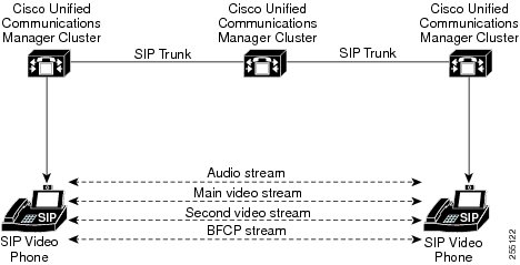
Page 899
enabled by default. You need not perform any additional configuration for the phone to support BFCP.
For more information, see Generate a Phone Feature List, on page 5.
Presentation Sharing using BFCP Configuration Task Flow
Complete the following tasks to enable Presentation sharing using the Binary Floor Control Protocol (BFCP).
Procedure
Purpose
Command or Action
Enables BFCP support on all SIP trunks in the
call flow.
Enable BFCP Support for SIP Trunks, on page
857
Step 1
Enables BFCP support in the third-party phone
configuration, if you are using third-party SIP
endpoints.
Enable Presentation Sharing using BFCP for
Third-Party Phones, on page 858
Step 2
Enable BFCP Support for SIP Trunks
If you are using Presentation sharing with BFCP, the feature must be enabled in the SIP Profile that is used
by all trunks in the messaging or call flow. The BFCP stream will be rejected by any trunk that does not
support presentation sharing.
Procedure
Step 1
Enable BFCP support within the SIP Profile that is used by the SIP trunk:
a)
From the Cisco Unified CM Administration, choose Device > Device Settings > SIP Profile.
b) Perform either of the following steps:
• Click Find to select an existing SIP profile.
• Click Add New to create a new SIP profile.
c)
In the SDP Information section, check the Allow Presentation Sharing using BFCP check box to
enable BFCP in the Unified Communications Manager.
By default, the check box is unchecked. For presentation sharing, BFCP must be enabled for all SIP trunks
between the Unified CM clusters.
d) Complete any other fields in the SIP Profile Configuration window. For more information on the fields
and their configuration options, see the system Online Help.
e)
Click Save.
Step 2
Associate the BFCP enabled SIP Profile to your SIP trunks:
a)
From the Cisco Unified CM Administration, choose Device > Trunks.
b) Click Find and select an existing SIP trunk.
Feature Configuration Guide for Cisco Unified Communications Manager, Release 15 and SUs
857
SIP Interoperability
Presentation Sharing using BFCP Configuration Task Flow
Page 900
c)
In the SIP Information section, choose the SIP Profile for which you enabled BFCP to share the
presentation in the intercluster call from the SIP Profile drop-down list.
d) Click Save.
e)
Repeat this step for all SIP trunks that will be in the call flow of a BFCP session.
Enable Presentation Sharing using BFCP for Third-Party Phones
If you want to use Presentation sharing using BFCP with third-party SIP Phones, you must make sure that
the feature is enabled for the endpoint. This feature is supported by the following third-party phone types:
• Third-party SIP Device (Advanced)
• Third-party AS-SIP Endpoint
Procedure
Step 1
From Cisco Unified CM Administration, choose Device > Phone.
Step 2
Click Find and select an existing third-party SIP phone.
Step 3
Check the Allow Presentation Sharing using BFCP check box.
Step 4
Click Save.
Feature Configuration Guide for Cisco Unified Communications Manager, Release 15 and SUs
858
SIP Interoperability
Enable Presentation Sharing using BFCP for Third-Party Phones
Page 901
C H A P T E R 73
Video Telephony
• Video Telephony Overview, on page 859
• Video Telephony Support, on page 859
• Video Network, on page 863
• Video Telephony Configuration Task Flow, on page 865
• H.323 Video, on page 865
• Video Support, on page 870
• Video Features , on page 873
• QoS for Video Networks , on page 875
Video Telephony Overview
Unified Communications Manager supports video telephony and thus unifies the world of voice and video
calls. Video endpoints use Unified CM call-handling features and access a unified voice and video solution
for dialing and connecting video calls.
The Unified Communications Manager video telephony solution offers these features:
• Supports video and video-related features, such as Far-End Camera Control (FECC)
• Supports multiple logical channels that are needed to allow the transmission of video streams
• Transmits midcall, media-related messages that are needed for video (that is, transmits commands or
indications that are needed for video calls)
• Supports H.323, Skinny Client Control Protocol (SCCP), and Session Initiation Protocol (SIP)
• Enhances locations and regions to provide Bandwidth Management
• Provides serviceability information, such as Call Detail Records (CDRs), about video calls
Video Telephony Support
The following sections discuss the details of video telephony in the Unified Communications Manager
environment.
Feature Configuration Guide for Cisco Unified Communications Manager, Release 15 and SUs
859

Page 902
Video Calls
The typical video call includes two or three Real-Time Protocol (RTP) streams in each direction (that is, four
or six streams). The call can include the following stream types:
• Video (H.261, H.263, H.263+, H.264-SVC, X-H.264UC, H.264-AVC, H.265, AV1 and VT Camera
wideband video codecs)
• Far-End Camera Control (FECC) - Optional
• Binary Floor Control Protocols (BFCP)
Call control for video calls operates the same way as the call control that governs all other calls. For more
information, see the Configure Media Resources chapter in the System Configuration Guide. You can also
see, Configure Conference Bridges chapter in the System Configuration Guide for details on how Unified
Communications Manager can allocate a video conference bridge automatically.
Note
Real-Time Transport Control Protocol Pass-Through in MTP Topologies
An IOS Media Terminate Point (MTP) before 15.2(2)T, cannot pass-through Real-Time Transport Control
Protocol (RTCP) packets and therefore cannot exchange Real-Time Protocol (RTP) feedback data to enhance
the RTP transmission. The primary function of RTCP is to provide feedback on media distribution by
periodically sending statistics to participants in a streaming multimedia session. RTCP gathers statistics for
a media connection and information such as transmitted octet and packet counts, lost packet counts, jitter, and
round-trip delay time. An application may use this information to control the quality of service parameters,
perhaps by limiting flow or using a different codec.
IOS MTP Version 15.2(2)T and later supports RTCP pass-through capability so that the endpoint in a call
with an MTP present can still provide feedback and status on an RTP transmission. RTCP pass-through
capability applies to media channels.
The RTCP pass-through feature is not limited to a specific call signaling protocol. For example, it can be
SIP-SIP, SIP-nonSIP, or nonSIP-nonSIP.
For Unified CM to allocate an RTCP pass-through capable MTP specifically, the call needs to fulfill the
following conditions:
• An MTP is requested for a feature that requires the MTP to be in media pass-through mode. For example,
TRP, DTMF translation, IP address V4/V6 translation, and so on. RTCP pass-through is only applicable
when the media is in pass-through mode.
• The RTCP pass-through MTP needs to be included in the Media Resource Group Lists (MRGL) of the
endpoint that sponsors the MTP. MTP can be inserted by RSVP, TRP, DTMF mismatch reasons.
• When the call is capable of establishing video channels, Unified CM attempts to search for an RTCP
pass-through capable MTP. For example, Unified CM picks an RTCP pass-through capable MTP from
other non-capable ones in the MRGL. If an RTCP pass-through capable MTP is not available, then
Unified CM stills allocate an MTP for the call.
• When the call is capable of establishing an audio channel only, Unified CM does not intentionally request
an RTCPpass-through capable MTP for the non-video calls. However, if the MRGL only contains
RTCPpass-through capable MTP(s), then Unified CM inserts one of those into the audio call.
Feature Configuration Guide for Cisco Unified Communications Manager, Release 15 and SUs
860
SIP Interoperability
Video Calls

Page 903
• The call also needs to fulfill the current CAC bandwidth for video calls to have an RTCP pass-through
capable MTP.
If a call initially establishes with a non-RTCP pass-through capable MTP (before version 15.2(2)T) present
in the call, and the call escalates into a video-capable call, Unified CM does not reallocate to an RTCP
pass-through capable MTP. In that case, even though the call has been escalated to a video call, the existing
MTP does not allow RTCP packets to be passed through.
Note
Video Codecs
Common video codecs include H.261, an older video codec, H.263, a newer codec that gets used to provide
internet protocol (IP) video, and H.264, a high-quality codec. The system supports H.264 for calls that use
the Skinny Client Control Protocol (SCCP), H.323, and SIP on originating and terminating endpoints only.
The system also supports regions and locations.
Unified Communications Manager maintains the offerer's video codec ordering preference when making the
answer, if possible. H.265 is the preferred video codec is available on the endpoints, otherwise, Unified
Communications Manager follows the following codec preference preference order:
Description
Codecs
Preference Order
Provides higher quality video using lower bandwidth.
H.265 (HEVC)
1
Allows rendering of variable quality video from the same media
stream, by disregarding a subset of the packets received.
Note
H. 264 SVC is a new annex to the H.264-AVC video
compression standard; meaning it is an enhancement on top of
H.264-AVC. It provides the ability to encapsulate multiple video
streams at various frame-rates and resolutions in one container.
H.264 (SVC)
2
Microsoft-Proprietary Variant
X-H.264UC (Lync)
3
Advanced Video Coding
H.264 (AVC)
4
Feature Configuration Guide for Cisco Unified Communications Manager, Release 15 and SUs
861
SIP Interoperability
Video Codecs

Page 904
Description
Codecs
Preference Order
H.263 and H.261 codecs exhibit the following parameters and
typical values:
• Bit rates range from 64 kb/s to a few mb/s. These bit rates
can exist in any multiple of 100 b/s. H.261 and H.263 can
function with bit rates lower than 64 kb/s, but video quality
suffers in such cases.
• One-quarter Common Interchange Format (QCIF)
(Resolution equals 176x144.)
• Common Interchange Format (CIF) (Resolution equals
352x288.)
• 4CIF (Resolution equals 704x576.)
• Sub QCIF (SQCIF) (Resolution equals 128x96.)
• 16CIF (Resolution equals 1408x1152.)
• Custom Picture Format
• Resolution:
• Frame Rate: 15 frames per second (fps), 30 fps
• Annexes: F, D, I, J, K, L, P, T, N
H.263
5
H.261
6
The bandwidth of video calls equals the sum of the audio bandwidth and the video bandwidth. The total
bandwidth does not include overhead.
A 384-kb/s video call may comprise G.711 at 64 kb/s (for audio) plus 320 kb/s (for video). This sum
does not include overhead. If the audio codec for a video call is G.729 (at 24 kb/s), the video rate
increases to maintain a total bandwidth of 384 kb/s. If the call involves an H.323 endpoint, the H.323
endpoint may use less than the total available video bandwidth. Regardless of protocol, the endpoint
may always choose to send at less than the max bit rate for the call.
AV1 Codec Support
AV1 is a next-generation video codec developed by the Alliance for Open Media. The benefits of AV1 are:
• Reduced bandwidth consumption and better visual quality by utilizing better compression efficiency
compared to other video encodings
• Enables video for users on very low bandwidth networks
• Significant screen sharing efficiency improvements over other codecs
Unified Communication Manager supports negotiation of AV1 codec to establish media if endpoints support
the AV1 codec.
When both endpoints support Multiple Codecs in Answer, Unified CM negotiates all the matching codecs
including AV1 based on the preference order received. The endpoint will then use one of the codecs from the
Feature Configuration Guide for Cisco Unified Communications Manager, Release 15 and SUs
862
SIP Interoperability
Video Codecs
Page 905
negotiated codec list for media streaming. In a low bandwidth environment, the AV1 codec is preferred by
the endpoint over other codecs in the negotiated list.
When both the endpoints involved in the call do not support the Multiple Codec in Answer, and the AV1 is
the preferred codec over other codecs, Unified CM selects AV1 as the negotiated codec.
AV1 codec is not yet supported on TelePresence endpoints.
Note
Video Network
The following illustration provides an example of a video network that uses a single Unified Communications
Manager cluster. In a successful video network, any endpoint can call any other endpoint. Video availability
only exists if both endpoints are video-enabled. Video capabilities extend across trunks.
Feature Configuration Guide for Cisco Unified Communications Manager, Release 15 and SUs
863
SIP Interoperability
Video Network

Page 906
The Cisco video conference portfolio comprises the following video bridges:
• Cisco TelePresence MCU series
• Webex Meeting Server
The Cisco UC Endpoints portfolio comprises the following endpoints that support video:
For more information on Cisco UC Endpoint portfolio that support vedio, see Compatibility Matrix.
Third-party SIP video endpoints are capable of connecting to Cisco Unified Communications Manager as a
line-side device or as a trunk-side device. For more information, see Third-Party SIP Endpoints.
Note
Feature Configuration Guide for Cisco Unified Communications Manager, Release 15 and SUs
864
SIP Interoperability
Video Network

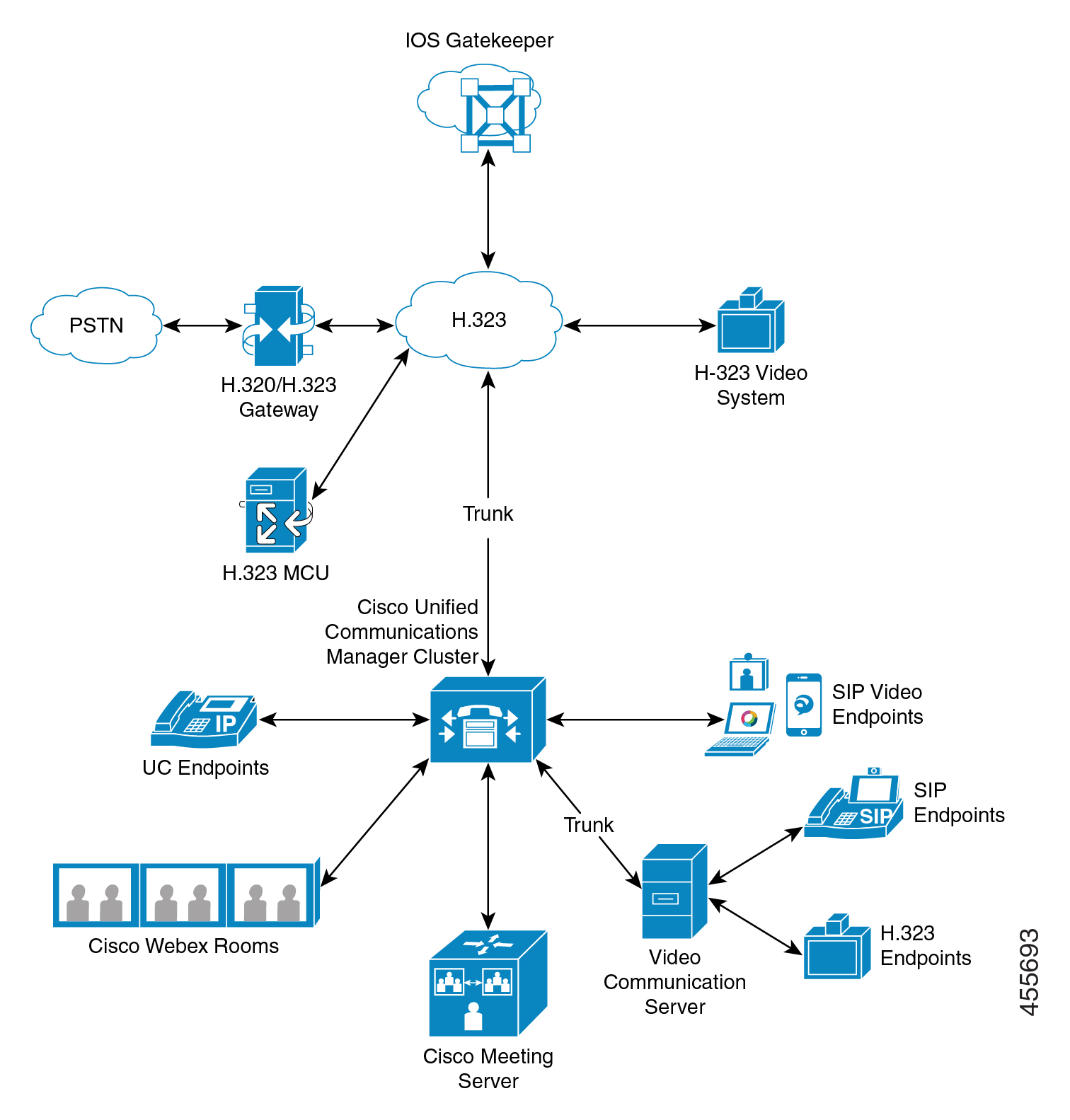
Page 907
Video Telephony Configuration Task Flow
To configure video telephony in Cisco Unified Communications Manager Administration follow these steps.
Procedure
Step 1
Configure regions for video call bandwidth if you use regions for call admission control.
Note
All devices include a default region, which defaults to 384 kb/s for video. You can set the bandwidth setting
in Region configuration high enough for the desired resolution (For example, increase to 2Mb/s for
high-definition video call).
Step 2
Configure locations for video call bandwidth if you use locations for call admission control.
Step 3
(Optional) Configure the RSVP service parameters, or set the RSVP policy in the Location Configuration
window if using RSVP for bandwidth management of SIP video calls.
Step 4
Configure the appropriate conference bridge for your network to use a Cisco video conference bridge.
Step 5
Configure the media resource groups and media resource group lists for the user accordingly to configure a
user to use the video conference bridge instead of using other conference bridges.
Step 6
Configure the H.323 gateways in your system to retry video calls as audio calls (default behavior) or configure
AAR groups and route/hunt lists to use alternate routing for video calls that do not connect.
Step 7
Configure the H.323 phones in your system to retry video calls as audio calls (default behavior) or configure
AAR groups and route/hunt lists to use alternate routing for video calls that do not connect. Choose Enabled
for Video Capabilities.
Step 8
Configure the H.323 trunks in your system to retry video calls as audio calls (default behavior) or configure
AAR groups and route/hunt lists to use alternate routing for video calls that do not connect.
Step 9
Configure the Cisco Unified IP Phones that will support video.
Step 10
Configure the third-party SIP endpoints that will support video.
Step 11
Configure the SIP trunks in your system to retry video calls as audio calls (default behavior).
H.323 Video
H.323 video exhibits the following characteristics:
• H.323 endpoints can be configured as H.323 phones, H.323 gateways, or H.323 trunks.
• Call forwarding, dial plan, and other call-routing-related features work with H.323 endpoints.
• H.323 video endpoints cannot initiate hold, resume, transfer, park, and other similar features.
• If an H.323 endpoint supports the empty capability set (ECS), the endpoint can be held, parked, and so
forth.
Feature Configuration Guide for Cisco Unified Communications Manager, Release 15 and SUs
865
SIP Interoperability
Video Telephony Configuration Task Flow
Page 908
• Some vendors implement call setup in such a way that they cannot increase the bandwidth of a call when
the call gets transferred or redirected. In such cases, if the initial call is audio, users may not receive
video when they are transferred to a video endpoint.
• No video media termination point (MTP) nor video transcoder currently exists. If an audio transcoder
or MTP is inserted into a call, that call will be audio only. This is true when the IPVC audio transcoding
capabilities is not being used. When the IPVC transcoders are used, you can transcode the audio and
send/receive video.
• For H.323 video calls, users must specify video call bandwidth.
H.239-Extended Video Channels in H.323 Call
The extended video channels feature works via H.239 protocol and enables multiple video channel support.
Cisco Unified Communications Manager supports negotiating an extended video channel using the H.239
protocol in direct point-to-point H.323 calls. This also includes calls across the H.323 intercluster trunk.
Cisco Unified Communications Manager supports all H.239 associated support signals and commands that
are specified in the H.239 recommendation.
The following sections describes characteristics which apply to the extended video channels feature.
Support for Third-Party H.323 Devices
The extended video channel feature supports H.239 interoperability among third-party video endpoints and
Cisco Unified Voice Conferencing. Cisco Unified Communications Manager allows an extended video channel
to be used for presentation and live meeting transmission. This feature focuses on multiple video channel
support via H.245 signaling. The following presentation applications provide basis for this multichannel
support:
• Natural Presenter package by the third-party vendor video endpoint
• People + Content by the third-party vendor Polycom
Both Natural Presenter package and People + Content use the H.239 protocol to negotiate capabilities and
define the roles of the additional video channels.
Natural Presenter package by video endpoint and People + Content by Polycom only support H.239 for the
presentation mode.
Be aware that the presentation applications that are offered by video endpoint and Polycom are optional
features. You must have one of these options and H.239 enabled in both caller and callee endpoints to negotiate
second video channels or the call will be limited to a single video channel.
Note
H.323 Devices Invoke Presentation Feature
Cisco and Polycom video endpoints allow the user to share presentation materials from various components
(for example, VCR, Projector, PC, and so on). The components can physically connect with the endpoints,
and the PC can also run presentation applications that are provided by the vendor to transmit the presentation
image. The source of presentation and the component connection with the video endpoint are irrelevant to the
mechanism of establishing video channels by using H.239.
Feature Configuration Guide for Cisco Unified Communications Manager, Release 15 and SUs
866
SIP Interoperability
H.239-Extended Video Channels in H.323 Call

Page 909
For details on setting up presentation sources, see the video endpoint user guide.
Note
When two H.239-enabled endpoints attempt to establish a video call, they declare their video capabilities for
the main video channel for meeting participants and their extended video capabilities (H.239 capabilities) for
the second video channel. The following contents comprise H.239 capability signals:
1.
The endpoints send signals to indicate that the devices support H.239. They also send associated commands
and indication signals for managing the second video channel. This enables both the endpoints to be aware
that the call is capable of opening multiple video channels.
2.
The endpoints sends out one or more extended video codec capabilities to express video codec capabilities
for second channels. The endpoint must specify the role of the second video channel. The defined role
labels can be
• Live-video-This channel gets processed normally and is suitable for live video of people
• Presentation-This channel relays a token-managed presentation that is distributed to the devices
After the capabilities have been exchanged, both endpoints immediately open two-way audio channels and
the main video channels as in the traditional video calls.
Opening Second Video Channels
Depending on the third-party endpoint implementation, the second video channel is handled differently among
vendors.
Natural Presenter Package by Tandberg
Video endpoints initiates the second video channel on demand. A video endpoint device does not open the
second video channel immediately after the main video channel is established. The second channel gets opened
when one of the callers (the presenter) specifies the source of the presentation and invokes a command to start
the presentation.
When a video endpoint user decides to start sharing the presentation, video endpoint requests the other call
party to open an extended video channel for receiving the presentation image; therefore, a video endpoint-video
endpoint call has only one-way second video channel.
People + Content by Polycom
Unlike video endpoint, a Polycom video endpoint initiates the second video endpoint immediately as a part
of the default mechanism, after both parties have confirmed that additional video channels can be supported.
Feature Configuration Guide for Cisco Unified Communications Manager, Release 15 and SUs
867
SIP Interoperability
Opening Second Video Channels

Page 910
The channel established gets automatically if both parties support H.239 and have the extended video channel
feature enabled. However, the additional channel does not show anything until one of the parties start to share
presentation.
Polycom initiates a request for the second video channel to the other call party regardless of the usage of the
second video channel; therefore, in a Polycom-Polycom call, two-way video channels get opened between
the devices even if only one of them sends out presentation image/video.
This implementation ensures that both call parties have the second video channel ready for transmission when
the call parties decide to take the token to present something. Although one of the two video channels remains
idle (not sending anything), the Polycom device controls bandwidth to ensure load efficiency.
This difference in handling second video channels does not affect the implementation of H.239. Unified
Communications Manager does not initiate any receiving channel request in an H.323-H.323 call. Unified
Communications Manager simply relays all channel requests from one terminal to another.
Unified Communications Manager does not enforce two-way transmission for the second set of video channels
because this does not represent a requirement in the H.239 protocol.
Note
Call Admission Control (CAC) on Second Video Channels
The following call admission control policies of Cisco Unified Communications Manager get applied to the
second video channels:
Cisco Unified Communications Manager restricts the bandwidth usage by the second video channels on the
basis of location configuration. When the second video channel is being established, Cisco Unified
Communications Manager makes sure that enough video bandwidth stays available within the location pool
and reserves bandwidth accordingly. If the required bandwidth is not available, Cisco Unified Communications
Manager instructs the channel to reduce the available bandwidth to zero.
No change occurs in the region configuration or policies to support the second video channels.
Traditionally, Cisco Unified Communications Manager region policy has only supported a call with a single
video channel and the total bandwidth usage of this call never gets larger than what the region configuration
specifies.
If the administrator sets a finite region video bandwidth restriction for an H.239 call, Cisco Unified
Communications Manager will violate the region policy because the region value will get used against the
bandwidth that is requested for each video channel independently.
Example
If the region video bandwidth is set to 384Kbps and the audio channel uses 64Kb/s,
the maximum allowed bandwidth for each video channel will be (384Kb/s - 64Kb/s)=
320Kb/s.
i.e. the maximum bandwidth to be used by the H.239 call will be (audio bw + 2*(384
- audio
bw)) = 704Kb/s, which goes beyond the 384Kb/s bandwidth that the region specifies.
Feature Configuration Guide for Cisco Unified Communications Manager, Release 15 and SUs
868
SIP Interoperability
Call Admission Control (CAC) on Second Video Channels

Page 911
You should consider relaxing both region and location bandwidth restrictions for H.239 calls, so the H.239
devices are allowed to readjust and balance load for both the video channels without Cisco Unified
Communications Manager intervention.
Note
Number of Video Channels Allowed
Unified Communications Manager supports only a maximum of two video channels due to the following
reasons:
• Both Cisco and Polycom only support two video channels, one of which is for main video, and the other
is for presentation.
• H.239 only defines an Additional Media Channel (AMC) for H.320-based system to partition the traditional
H.320 video channel for the purpose of presentation.
H.239 Commands and Indication Messages
Command and Indication (C&I) messages get used for H.239 to manage tokens for the Presentation and Live
roles and to permit devices to request release of video flow control to enable the operation of additional media
channels. Cisco Unified Communications Manager supports all the C & I messages. Whenever Cisco Unified
Communications Manager receives C&I messages, it relays them to the call party accordingly.
Be aware that the flow control release request and response messages can be used to request that the far end
release flow control, so it allows an endpoint to send the indicated channel at the indicated bit rate.
Be aware that the call party may or may not honor the request as is indicated by flow control release response.
Note
The Presentation role token messages allow an H.239 device to acquire the token for presentation. The other
call party may accept or reject the request. The presenter device sends out a token release message when it is
no longer needed.
Topology and Protocol Interoperability Limitation
Cisco Unified Communications Manager supports only H.239 in H.323 to H.323 calls. Cisco Unified
Communications Manager allows H.239 calls to be established across H.323 intercluster trunk or multiple
nodes. If an H.239-enabled device attempts to make a call with a non-H323 end, the H.239 capabilities will
get ignored and the call will get conducted like the traditional video calls that are supported by Cisco Unified
Communications Manager.
Cisco Unified Communications Manager does not support a second video channel when a media termination
point or transcoder is inserted into the call. If it happens, the call will fall back to normal video calls.
Midcall Feature Limitation
Cisco Unified Communications Manager supports opening second video channels only in direct H.323 to
H.323 calls.
Feature Configuration Guide for Cisco Unified Communications Manager, Release 15 and SUs
869
SIP Interoperability
Number of Video Channels Allowed

Page 912
Do not attempt to invoke any midcall features such as call transfer or hold/resume operations. Doing so can
lead to problems and the second video channel can get disconnected.
Caution
Video Support
Unified Communications Manager supports video over H.323, SCCP and SIP protocols.
Skinny Client Control Protocol Video
Skinny Client Control Protocol video exhibits the following characteristics:
• If a phone that is running Skinny Client Control Protocol reports video capabilities, Cisco Unified
Communications Manager automatically opens a video channel if the other end supports video.
• For Skinny Client Control Protocol video calls, system administration determines video call bandwidth
by using regions. The system does not ask users for bit rate.
SIP Video
SIP video supports the following video calls by using the SIP Signaling Interface (SSI):
• SIP to SIP
• SIP to H.323
• SIP to SCCP
• SIP intercluster trunk
• H.323 trunk
• Combination of SIP and H.323 trunk
SIP video calls also provide media control functions for video conferencing.
Unified Communications Manager video supports SIP on both SIP trunks and lines support video signaling.
SIP supports the H.261, H.263, H.263+, H.264 (AVC), H.264 (SVC), X-H.264UC (Lync), and AV1 video
codecs (it does not support the wideband video codec that the VTA uses).
Only some of the endpoints supports AV1 codec. For more information, see Compatability Matrix.
Note
Configuring SIP Devices for Video Calls
Perform the following steps to enable video calls on SIP devices:
Feature Configuration Guide for Cisco Unified Communications Manager, Release 15 and SUs
870
SIP Interoperability
Video Support


Page 913
SIP Trunks
• On the Trunk Configuration window in Unified Communications Manager, check the Retry Video Call
as Audio check box if you want the call to use audio when the video connection is not available.
• Reset the trunk.
Third-Party SIP Endpoints
• On the Phone Configuration window in Cisco Unified Communications Manager Administration, check
the Retry Video Call as Audio check box if you want the call to use audio when the video connection
is not available.
• Reset the endpoint.
Cisco Video Conference Bridges
Unified Communications Manager supports a variety of solutions for video conferencing. The following video
conference bridges support ad hoc and meet-me video conferencing:
• Cisco TelePresence MCU
• Cisco TelePresence Conductor
• Cisco Meeting Server
Cisco TelePresence MCU Video Conference Bridge
Cisco TelePresence MCU is a set of hardware conference bridges for Cisco Unified Communications Manager.
The Cisco TelePresence MCU is a high-definition (HD) multipoint video conferencing bridge. It delivers up
to 1080p at 30 frames per second, full continuous presence for all conferences, full transcoding, and is ideal
for mixed HD endpoint environments. The Cisco TelePresence MCU supports SIP as the signaling call control
protocol. It has a built in Web Server that allows for complete configuration, control, and monitoring of the
system and conferences. The Cisco TelePresence MCU provides XML management API over HTTP.
Cisco TelePresence MCU allows both ad hoc and meet-me voice and video conferencing. Each conference
bridge can host several simultaneous, multiparty conferences. Cisco TelePresence MCU must be configured
in Port Reservation mode.
Cisco TelePresence Conductor Video Conference Bridge
Cisco TelePresence Conductor provides intelligent conference administrative controls and is scalable, supporting
device clustering for load balancing across MCUs and multiple device availability. Administrators can
implement the Cisco TelePresence Conductor as either an appliance or a virtualized application on VMware
with support for Cisco Unified Computing System (Cisco UCS) platforms or third-party-based platforms.
Multiway conferencing, that allows for dynamic two-way to three-way conferencing, is also supported.
Cisco TelePresence Conductor supports both ad hoc and meet-me voice and video conferencing. Cisco
TelePresence Conductor dynamically selects the most appropriate Cisco TelePresence resource for each new
conference. Ad hoc, “MeetMe” and scheduled voice and video conferences can dynamically grow and exceed
the capacity of individual MCUs. One Cisco TelePresence Conductor appliance or Cisco TelePresence
Conductor cluster has a system capacity of 30 MCUs or 2400 MCU ports. Up to three Cisco TelePresence
Conductor appliances or virtualized applications may be clustered to provide greater resilience.
Feature Configuration Guide for Cisco Unified Communications Manager, Release 15 and SUs
871
SIP Interoperability
Cisco Video Conference Bridges
Page 914
Cisco Meeting Server
The Cisco Meeting Server conference bridge solution allows Ad Hoc, Meet-Me, Conference Now, and
Rendezvous conferences. This conference bridge offers premises-based audio, video, and web conferencing,
and works with third-party on-premises infrastructure. It scales for small or large deployments. You can add
capacity incrementally as needed, to ensure that you can support the current and future needs of your
organization. This conference bridge provides advanced interoperability. Any number of participants can
create and join meetings from:
• Cisco or third-party room or desktop video systems
• Cisco Jabber Client
• Cisco Meeting App (can be native or with a WebRTC compatible browser)
• Skype for Business
A minimum release of Cisco Meeting Server 2.0 is required to use the Cisco Meeting Server conference
bridge.
The Cisco Meeting Server supports SIP as the signaling call control protocol. It has a built in Web Server that
allows for complete configuration, control, and monitoring of the system and conferences. The Cisco Meeting
Server provides XML management API over HTTP.
Cisco Meeting Server is enhanced to support AV1 codec and does not support H.265 video codec and Far
End Camera Control (FECC).
Note
Video Encryption
Unified Communications Manager supports encryption of audio, video, and other media streams so long as
the individual endpoints involved in the communication also support encryption. Unified CM uses the Secure
Real-Time Transport Protocol (SRTP) to encrypt the media streams. Some of the features include:
• Support for SIP and H.323 endpoints
• Support for encryption of main audio and video line while operating in Media Termination Point (MTP)
passthru mode
• Support for multiple encryption methods
• Support for Session Description Protocol (SDP) crypto-suite session parameters in accordance with RFC
4568
To provide encrypted communications, encryption keys are exchanged between the endpoints and Unified
Communications Manager during the SIP call setup. For this reason, the SIP signaling should be encrypted
using TLS. During the initial call setup, the video endpoints exchange a list of encryption methods they
support, select an encryption suite supported by both endpoints, and exchange encryption keys. If the endpoints
cannot agree on a common encryption suite, the media streams are unencrypted and transported using the
Real-Time Transport Protocol (RTP).
Feature Configuration Guide for Cisco Unified Communications Manager, Release 15 and SUs
872
SIP Interoperability
Cisco Meeting Server

Page 915
If the individual endpoints do not support encryption, the communication will take place using RTP.
Note
Configure Interop with VCS
Perform the following steps on the SIP trunk that connects Unified Communications Manager to Cisco VCS
to enable Unified CM to interoperate with a Cisco VCS.
Procedure
Step 1
From Cisco Unified CM Administration, choose Device > Trunk.
Step 2
Perform one of the following:
• Click Find and select an existing trunk.
• Click Add New to configure a new trunk.
Step 3
In the Trunk Configuration window, choose the Trunk Type, Device Protocol, Trunk Service Type that
connects Unified Communications Manager to the Cisco VCS and click Next.
Step 4
In the SIP Profile drop-down list, choose Standard SIP Profile for VCS.
Step 5
In the Normalization Script drop-down list, choose vcs-interop.
Step 6
In the Normalization Script area, leave the Parameter Name and Parameter Value fields empty. If these
fields are populated with values, delete the contents of the field.
Step 7
Click Save.
Video Features
The following video-related features are supported in SIP video networks:
• Binary Floor Control Protocol (BFCP)
• Encrypted iX Channel
• Far End Camera Control (FECC)
Endpoint Support for the Binary Floor Control Protocol
Unified Communications Manager provides support for the Binary Floor Control Protocol (BFCP) for specific
Cisco and third-party video endpoints. BFCP allows users to share a presentation within an ongoing video
conversation.
For more information, see chapter Configure Presentation Sharing using BFCP in Feature Configuration Guide
for Cisco Unified Communications Manager.
Feature Configuration Guide for Cisco Unified Communications Manager, Release 15 and SUs
873
SIP Interoperability
Configure Interop with VCS

Page 916
Encrypted iX Channel
Unified Communications Manager supports an encrypted iX channel. The iX channel provides a reliable
channel for multiplexing application media between SIP phones in a video conference. Encrypted iX Channel
uses DTLS to add security to your deployment and ensures that the application media is sent over the iX
Channel is private and cannot be viewed by intermediate parties who attempt to intercept media.
IOS MTP and RSVP agents in pass through mode also support encrypted iX Channel.
Configuration
To enable an encrypted iX Channel on Unified Communications Manager, you must:
• Check the Allow iX Application Media check box in the SIP Profile Configuration that is used by any
intermediate SIP trunks. This setting turns on the iX channel negotiation.
• Configure the Secure Call Icon Display Policy service parameter to enable a secure lock icon. By
default, the setting is All media except BFCP and iX transports must be encrypted.
Encryption Modes
There are two types of Session Description Protocol (SDP) offers thatUnified Communications Manager
supports for iX Channel encryption for encrypted phones. This encryption type is driven by what the endpoints
support and is not a configurable item in the Unified Communications Manager.
• Best Effort Encryption—The SDP offer is for an encrypted iX Channel, but falls back to a non-encrypted
iX Channel if the SIP peers do not support it. This approach can be used if encryption is not mandatory
in the solution.
For example, encryption is mandatory within the cloud, and not in a single enterprise.
Best-Effort iX Encryption
m=application 12345 UDP/UDT/IX *
a=setup:actpass
a=fingerprint: SHA-1 <key>
• Forced Encryption—The SDP offer is for an encrypted iX Channel only. This offer is rejected if the
SIP peers do not support iX Channel encryption. This approach can be used in deployments where
encryption is mandatory between endpoints.
For example, encryption is mandatory between the two SIP devices.
Forced iX Encryption
m=application 12345 UDP/DTLS/UDT/IX *
a=setup:actpass
a=fingerprint: SHA-1 <key>
By default, all Cisco IP Phones are set to offer Best Effort iX Encryption. However, you can reset this to
Forced Encryption by setting the Encryption Mode to On within the Product-Specific Configuration of Cisco
TelePresence endpoints, or by reconfiguring settings on the Cisco Meeting Server.
Feature Configuration Guide for Cisco Unified Communications Manager, Release 15 and SUs
874
SIP Interoperability
Encrypted iX Channel
Page 917
Non-Encrypted Modes
Unified Communications Managerenables negotiation of secure active control messages in media path from
endpoints in a meeting when the endpoint may not be deployed in a fully secure mode. For example, if the
endpoint is Off-Net and is registered with Unified CM in Mobile and Remote Access mode.
Prerequisite
Before you start using this feature, make sure that:
• System adheres to the export compliance requirement
• SIP trunk to the conference bridge is secure
Unified CM can negotiate the DTLS information in secure active control messages for non-secure endpoints
or softphones and receive messages in the following ways:
• Best Effort Encryption iX to On-Premise registered endpoints or softphones
• Forced iX Encryption to Off-Premise registered endpoints or softphones
Far End Camera Control Protocol Support
The Far End Camera Control (FECC) protocol allows you to control a remote camera. Within video calls,
FECC allows the party at one end of the call to control the camera at the far end. This control can include
panning the camera from one side to the other, tilting the camera, or zooming in and out. For video conferences
that use multiple cameras, FECC can be used to switch from one camera to another.
Unified Communications Manager supports the FECC protocol for video endpoints that are FECC-capable.
Cisco Unified Communications Manager supports FECC for SIP-SIP calls or H.323-H.323 calls, but does
not support FECC for SIP-H.323 calls. To support FECC, Unified Communications Manager sets the application
media channel through SIP or H.323 signaling. After the media channel is established, the individual endpoints
can communicate the FECC signaling.
QoS for Video Networks
Cisco Unified Communications Manager contains a number of administrative tools for managing Quality of
Service (QoS) for video networks:
• Bandwidth Management—Mange bandwidth allocations for specific Regions and Locations
• Enhanced Locations Call Admission Control
• Session Level Bandwidth Modifiers
• Flexible DSCP Markings
• Alternate Routing
Feature Configuration Guide for Cisco Unified Communications Manager, Release 15 and SUs
875
SIP Interoperability
Non-Encrypted Modes
Page 918
Bandwidth Management
Bandwidth allocations for audio and video calls are managed through regions and locations that you configure
in Cisco Unified Communications Manager Administration.
The amount of bandwidth available for a specific call must be able to manage the combination of all media
streams that are associated with the session, including voice, video, signaling, and any extra media, such as
a BFCP presentation. Cisco Unified Communications Manager contains features able to manage bandwidth.
Enhanced Locations Call Admission Control
Enhanced Locations Call Admission Control (CAC) enables you to control the audio and video quality of
calls over a wide-area (IP WAN) link by limiting the number of calls that are allowed on that link at the same
time. For example, you can use call admission control to regulate the voice quality on a 56-kb/s frame relay
line that connects your main campus and a remote site.
CAC verifies whether there is sufficient bandwidth available to complete a call. CAC can reject calls due to
insufficient bandwidth.
In Unified Communications Manager, locations-based call admission control works in conjunction with
regions to define the characteristics of a network link. Regions and locations work in the following manner:
• Regions allow the bandwidth of video calls to be set. The audio limit on the region may result in filtering
out codecs with higher bit rates. However, for video calls, the video limit constrains the quality (resolution
and transmission rate) of the video.
• Locations define the amount of total bandwidth available for all calls on that link. When a call is made
on a link the regional value for that call must be subtracted from the total bandwidth allowed for that
link.
For more information about call admission control, see chapter 'Configure Enhanced Locations Call Admission
Control' in System Configuration Guide for Cisco Unified Communications Manager
.
Session Level Bandwidth Modifiers
Unified Communications Manager provides location call admission control support for handling session level
bandwidth modifiers. Session level bandwidth modifiers are communicated as part of the parameters in the
SDP portion of the initial SIP signaling. These parameters indicate the maximum amount of bandwidth each
endpoint will support for that type of call. These parameters are used, along with regions and locations settings,
to set the bandwidth for each call.
During the initial call setup, both parties communicate to Unified Communications Manager their maximum
allowed bandwidth for the call. Unified Communications Manager passes this communication to the other
endpoint, but if the bandwidth that is specified by the endpoint is greater than the region setting, Unified
Communications Manager replaces the value with the region bandwidth value.
Unified Communications Manager uses the following rules to determine the amount of bandwidth to allocate
to a specific call:
• When Unified Communications Manager receives an Offer or Answer from an endpoint, it checks whether
there is a session level bandwidth modifier in the SDP:
Feature Configuration Guide for Cisco Unified Communications Manager, Release 15 and SUs
876
SIP Interoperability
Bandwidth Management
Page 919
• If there is a session level bandwidth modifier, Unified Communications Manager retrieves the
bandwidth value from the modifier. If there is more than one modifier type, it retrieves the modifier
in the following order of preference: Transport Independent Application Specific (TIAS), Application
Specific (AS), Conference Total (CT).
• If there is no session level bandwidth modifier, Unified Communications Manager retrieves the
bandwidth value from the sum of the media level bandwidth modifiers.
• The allocated bandwidth is the maximum of what the two endpoints support up to the maximum value
of the Region setting. The allocated bandwidth cannot exceed the region setting.
Unified Communications Manager uses the following logic when communicating with endpoints:
• When generating an Answer, Early Offer or Re-Invite Offer to an endpoint that contains more than one
session level bandwidth modifier type (TIAS, AS, CT), Unified Communications Manager uses the same
bandwidth value for each.
• When generating an answer, Unified Communications Manager uses the same session level bandwidth
modifier type (TIAS, CT, AS) that was received in the initial offer
• For backward compatibility, the older Unified Communications Manager suppresses the Session Level
Bandwidth Modifier when a video call is put on hold and music on hold (MOH) is inserted.
Video Resolution Support for SIP Phones
Cisco Unified Communications Manager supports the imageattr line in the SDP portion of the SIP header for
higher resolution video calls. Cisco SIP phones that support w360p (640 x 360), such as the 9951, 9971, and
8961, automatically select the best resolution for video calls depending on the following criteria:
• If the session level bandwidth is greater than 800Kb/s and the imageattr[640 x 480] line in the SDP exists,
then VGA is used.
• If the session level bandwidth is greater than 800Kb/s and the imageattr[640 x 480] line in the SDP does
not exist, then w360p is used.
• If the session level bandwidth is less than 800Kb/s but greater than 480 bits per second and the
imageattr[640 x 480] line exists, then VGA 15 frames per second is used.
If you currently have a Cisco IP Phone model 9951, 9971, or 8961 that supports w360p (640 x 360) video
resolution and are upgrading to Cisco Unified Communications Manager release 8.5(1) or later, you may
notice changes in the resolution of video calls. The w360p resolution was introduced at phone load 9.2(1).
Note
The following video call flow is between two 9951 phones (Phone A and Phone B) without imageattr line
support (for example, using Cisco Unified Communications Manager releases 8.0(1) and earlier):
1.
Phone A sends a SIP message with an imageattr line in the SDP.
2.
Cisco Unified Communications Manager deletes the imageattr line in the SDP and then sends the modified
SIP message to Phone B.
3.
Phone B attempts to send video with the w360p resolution because there is no imageattr line in the SDP
portion of the SIP header.
Feature Configuration Guide for Cisco Unified Communications Manager, Release 15 and SUs
877
SIP Interoperability
Video Resolution Support for SIP Phones

Page 920
The following video call flow is between two 9951 phones (Phone A and Phone B) with imageattr line support
(for example, using Cisco Unified Communications Manager releases 8.5(1) and later):
1.
Phone A sends a SIP message with the imageattr line in the SDP.
2.
Cisco Unified Communications Manager does not delete the imageattr line and sends the SIP message to
Phone B unchanged.
3.
Phone B attempts to send video with the VGA resolution.
Alternate Routing
If an endpoint cannot obtain the bandwidth that it needs for a video call, a video call retries as an audio call
for the default behavior. To use route/hunt lists or Automated Alternate Routing (AAR) groups to try different
paths for such video calls, uncheck the Retry Video Call as Audio setting in the configuration settings for
applicable gateways, trunks, and phones.
For more information, see Configure AAR Group section under Configure Call Routing chapter in the System
Configuration Guide for Cisco Unified Communications Manager.
Flexible DSCP Markings
Differentiated Services Code Point (DSCP) packet marking, is used to specify the class of service for each
packet. DSCP marking lets you prioritize certain types of calls or media over other types. For example, you
can prioritize audio over video so that, even if you experience network bandwidth issues, audio calls should
not experience bandwidth issues.
You can customize DSCP markings in either of these ways:
• Configure cluster wide service parameters to set the default DSCP settings for the cluster
• (Optional) For a subset of the DSCP categories, you can assign customized DSCP settings to devices via
the SIP Profile. For the devices that use the profile, the customized settings override the service parameter
defaults.
For more information on how to configure DSCP markings, see 'Configure Flexible DSCP Marking and Video
Promotion' chapter in the Feature Configuration Guide for Cisco Unified Communications Manager.
Phone Configuration for Video Calls
The following setting for video-enabled devices affects video calls:
• Retry Video Call as Audio-By default, this check box remains checked. Thus, if an endpoint (phone,
gateway, trunk) cannot obtain the bandwidth that it needs for a video call, call control retries the call as
an audio call. This setting applies to the destination devices of video calls.
• Video Capabilities Enabled/disabled-This drop-down list box turns video capabilities on and off.
Conference Control for Video Conferencing
Unified Communications Manager supports the following conference controls capabilities:
Feature Configuration Guide for Cisco Unified Communications Manager, Release 15 and SUs
878
SIP Interoperability
Alternate Routing
Page 921
• Roster/Attendee List
• Drop Participant
• Terminate Conference
• Show Conference Chairperson/Controller
• Continuous Presence
Unified Communications Manager also supports the following video conference capabilities for Skinny Client
Control Protocol (SCCP) phones:
• Display controls for video conferences. The SCCP phones can choose to use the continuous presence or
voice-activated mode to view the video conference. When a mode is chosen, a message gets sent to the
bridge to indicate which mode to use on the video channel. Switching between modes does not require
renegotiation of media.
• Display participant information such as the user name in the video stream. The system can use the
participant information for other conferencing features such as roster.
For more information, see 'Encrypted iX Channel' chapter in the Security Guide for Cisco Unified
Communications Manager.
Video Telephony and Cisco Unified Serviceability
Cisco Unified Serviceability tracks video calls and conferences by updating performance monitoring counters,
video bridge counters, and call detail records (CDRs).
Performance Counters
Video telephony events cause updates to the following Cisco Unified Serviceability performance monitoring
counters:
Cisco CallManager
• VCBConferenceActive
• VCBConferenceCompleted
• VCBConferenceTotal
• VCBOutOfConferences
• VCBOutOfResources
• VCBResourceActive
• VCBResourceAvailable
• VideoCallsActive
• VideoCallsCompleted
• VideoOutOfResources
Feature Configuration Guide for Cisco Unified Communications Manager, Release 15 and SUs
879
SIP Interoperability
Video Telephony and Cisco Unified Serviceability
Page 922
Gatekeeper
• VideoOutOfResources
CiscoH.323
• VideoCallsActive
• VideoCallsCompleted
Cisco Locations
• RSVP VideoCallsFailed
• RSVP VideoReservationErrorCounts
• VideoBandwidthAvailable
• VideoBandwidthMaximum
• VideoOutOfResources
Cisco SIP
• VideoCallsActive
• VideoCallsCompleted
Cisco Vedio Conference Bridge
• ConferencesActive
• ConferencesAvailable
• ConferencesCompleted
• ConferencesTotal
• OutOfConferences
• OutOfResources
• ResourceActive
• ResourceAvailable
• ResourceTotal
Video Bridge Counters
Video conference events cause updates to these Cisco video conference bridge performance monitoring
counters:
• ConferencesActive
• ConferencesAvailable
Feature Configuration Guide for Cisco Unified Communications Manager, Release 15 and SUs
880
SIP Interoperability
Video Bridge Counters
Page 923
• ConferencesCompleted
• ConferencesTotal
• OutOfConferences
• OutOfResources
• ResourceActive
• ResourceAvailable
• ResourceTotal
These counters also display in the Cisco Unified Communications Manager object with the VCB prefix.
Call Detail Records (CDRs)
Video telephony events cause updates to Call Detail Records (CDRs) in Cisco Unified Serviceability. These
CDRs include the following information:
• origVideoCap_Codec
• origVideoCap_Bandwidth
• origVideoCap_Resolution
• origVideoTransportAddress_IP
• origVideoTransportAddress_Port
• destVideoCap_Codec
• destVideoCap_Bandwidth
• destVideoCap_Resolution
• destVideoTransportAddress_IP
• destVideoTransportAddress_Port
• origRSVPStat
• destRSVPVideoStat
• origVideoCap_Codec_Channel2
• origVideoCap_Bandwidth_Channel2
• origVideoCap_Resolution_Channel2
• origVideoTransportAddress_IP_Channel2
• origVideoTransportAddress_Port_Channel2
• origVideoChannel_Role_Channel2
• destVideoCap_Codec_Channel2
• destVideoCap_Bandwidth_Channel2
• destVideoCap_Resolution_Channel2
Feature Configuration Guide for Cisco Unified Communications Manager, Release 15 and SUs
881
SIP Interoperability
Call Detail Records (CDRs)
Page 924
• destVideoTransportAddress_IP_Channel2
• destVideoTransportAddress_Port_Channel2
• destVideoChannel_Role_Channel2
Call Management Records (CMRs)
Video telephony events cause updates to Call Management Records (CMRs) in Cisco Unified Serviceability.
These CMRs include the following information:
• videoContentType Text String
• videoDuration Integer
• numberVideoPacketsSent Integer
• numberVideoOctetsSent Integer
• numberVideoPacketsReceived Integer
• numberVideoOctetsReceived Integer
• numberVideoPacketsLost Integer
• videoAverageJitter Integer
• videoRoundTripTime
• videoOneWayDelay
• videoTransmissionMetrics
Feature Configuration Guide for Cisco Unified Communications Manager, Release 15 and SUs
882
SIP Interoperability
Call Management Records (CMRs)
Page 925
P A R T XVII
Emergency Call Routing Regulations
• The US Federal Communications Commission (FCC) Emergency Call Routing Regulations, on page 885

Page 926
Page 927
C H A P T E R 74
The US Federal Communications Commission
(FCC) Emergency Call Routing Regulations
• Emergency Call Routing Regulations Overview, on page 885
• Configure Emergency Call Routing Regulations, on page 887
Emergency Call Routing Regulations Overview
Emergency Call Routing Regulation provides us with information in compliance with the US FCC laws on
how the Emergency Calls (911) are configured and routed in the US and non-US time zones.
The US FCC signed the following laws to ease public safety by encouraging and enabling the prompt
deployment of a nationwide, seamless communications infrastructure for emergency services.
The US FCC signed the following laws on Emergency Call (911) routing:
• Kari's Law—This law applies to Multi-Line Telephone Systems (MLTS) that serve users in settings such
as office buildings, campuses, and hotels. The FCC requires MLTS to enable users to dial 911 directly,
without dialing a prefix reach an outside line and notifies the front desk or security office when emergency
calls are made.
• Ray Baum's Act—Under section 506 of Ray Baum’s act, dispatch the location details (a street address,
building number, floor number, room number) with emergency calls regardless of the technological
platform used so that the 911 call centers receive the caller's location automatically and can dispatch
responders more quickly.
For more information on FCC laws, see https://www.fcc.gov/mlts-911-requirements
An Emergency Responder effectively manages calls in the telephony network to respond and handle all
emergency calls in compliance with local ordinances. It also dispatches location details and notifications are
dispatched to the Unified Communications Manager.
The following image shows the connection between the Emergency Responder and Unified Communications
Manager.
Feature Configuration Guide for Cisco Unified Communications Manager, Release 15 and SUs
885

Page 928
For more information on Cisco Emergency Responder, see Cisco Emergency Responder Administration
Guide.
Unified Communications Manager as MLTS
The Cisco Unified Communications Manager Administration is an MLTS that has an inbuilt software to detect
an absence of a direct 911 dial pattern for systems installed in the US time zone.
If the 911 route pattern isn’t enabled, the Cisco Unified CM Administration home page displays an alert
message: You have not configured a direct dial 911 pattern on this system. Federal Communication
Commission rules mandate that most multi-line telephone systems in the US have a direct dial 911
pattern.
If the system installed in a non-US time zone, where FCC laws aren't applicable, Emergency Call Routing
Regulations configuration page disabled in the Unified Communications Manager.
You should consult with their legal counselor on the applicability of FCC laws and acknowledge in the system.
Note
Feature Configuration Guide for Cisco Unified Communications Manager, Release 15 and SUs
886
Emergency Call Routing Regulations
Emergency Call Routing Regulations Overview

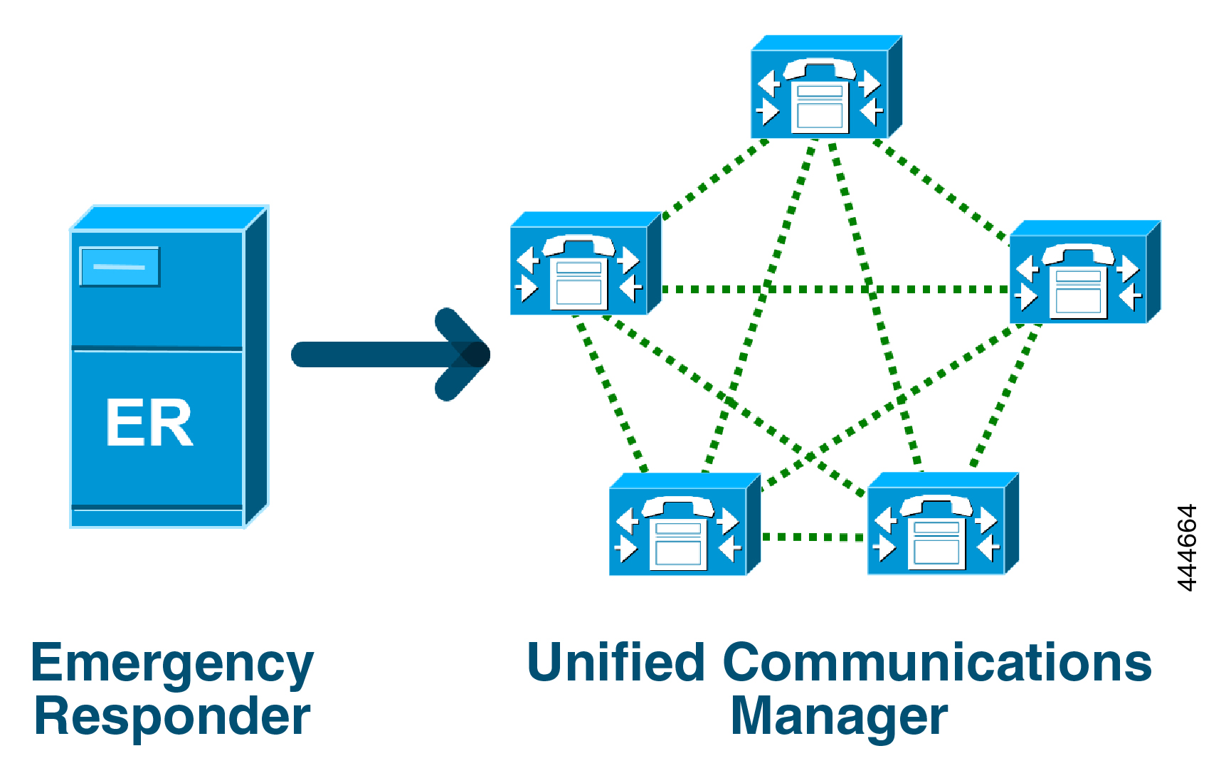

Page 929
Configure Emergency Call Routing Regulations
Emergency Call Routing Regulation configured on Unified Communications Manager to acknowledge and
configure the direct dial 911 route pattern in compliance with the laws.
Before you begin
Ensure to take a backup after you accept and configure FCC Laws for future reference.
Procedure
Step 1
To access the Emergency Call Routing Regulations window, perform either of the following:
• From Cisco Unified CM Administration, chooseAdvanced Features > Emergency Call Routing
Regulations
• Click the link available in the alert notification to configure the 911 route pattern on the home page.
Step 2
Check the I have read the above notification,and I have consulted my legal counsel to determine my
specific obligations check box to acknowledge the notification.
Step 3
Check the Take me to the 911 configuration page check box and click Submit to set up direct 911 notification
if the FCC laws are applicable. You are navigated to the Route Pattern Configuration window and by default,
a 911 pattern is configured in the Pattern Definition section.
Step 4
Choose an appropriate gateway, route, or trunk from the Gateway/Route List drop-down list for the configured
pattern. For more information on the other fields and their configurations, see Online Help.
Step 5
Click Save.
Note
If the system installed in the US time zone where FCC laws aren't applicable, acknowledge the law and check
the Disable any further notification regarding my 911 obligation check box in the Emergency Call Routing
Regulations window and click Submit to disable the 911 notifications.
If the laws aren't applicable, the administrator waives the notifications for future upgrades and new installations
of the 911 route pattern.
The configured settings get preserved for future upgrade. The alert notification disappears on the home page
and the Emergency Call Routing Regulations window gets disabled.
If the system has already created a 911 route pattern during upgrade or the time zone changed from non-US
to US timezone then the acknowledge page is grayed out.
Feature Configuration Guide for Cisco Unified Communications Manager, Release 15 and SUs
887
Emergency Call Routing Regulations
Configure Emergency Call Routing Regulations
Page 930
Feature Configuration Guide for Cisco Unified Communications Manager, Release 15 and SUs
888
Emergency Call Routing Regulations
Configure Emergency Call Routing Regulations