Document Metadata
Format: PDF 1.4
Title: Installation Guide for Cisco Unified Communications Manager and the IM and Presence Service, Release 15 and SUs
Author: Unknown
Creator: DITA Open Toolkit
Producer: XEP 4.30.961; modified using iText 2.1.7 by 1T3XT
Creation Date: D:20260413051229Z
Mod Date: D:20260412221409-07'00'
Page 1
Installation Guide for Cisco Unified Communications Manager and the
IM and Presence Service, Release 15 and SUs
First Published: 2023-12-18
Last Modified: 2026-03-17
Americas Headquarters
Cisco Systems, Inc.
170 West Tasman Drive
San Jose, CA 95134-1706
USA
http://www.cisco.com
Tel: 408 526-4000
800 553-NETS (6387)
Fax: 408 527-0883

Page 2
THE SPECIFICATIONS AND INFORMATION REGARDING THE PRODUCTS IN THIS MANUAL ARE SUBJECT TO CHANGE WITHOUT NOTICE. ALL STATEMENTS,
INFORMATION, AND RECOMMENDATIONS IN THIS MANUAL ARE BELIEVED TO BE ACCURATE BUT ARE PRESENTED WITHOUT WARRANTY OF ANY KIND,
EXPRESS OR IMPLIED. USERS MUST TAKE FULL RESPONSIBILITY FOR THEIR APPLICATION OF ANY PRODUCTS.
THE SOFTWARE LICENSE AND LIMITED WARRANTY FOR THE ACCOMPANYING PRODUCT ARE SET FORTH IN THE INFORMATION PACKET THAT SHIPPED WITH
THE PRODUCT AND ARE INCORPORATED HEREIN BY THIS REFERENCE. IF YOU ARE UNABLE TO LOCATE THE SOFTWARE LICENSE OR LIMITED WARRANTY,
CONTACT YOUR CISCO REPRESENTATIVE FOR A COPY.
The Cisco implementation of TCP header compression is an adaptation of a program developed by the University of California, Berkeley (UCB) as part of UCB's public domain version of
the UNIX operating system. All rights reserved. Copyright © 1981, Regents of the University of California.
NOTWITHSTANDING ANY OTHER WARRANTY HEREIN, ALL DOCUMENT FILES AND SOFTWARE OF THESE SUPPLIERS ARE PROVIDED “AS IS" WITH ALL FAULTS.
CISCO AND THE ABOVE-NAMED SUPPLIERS DISCLAIM ALL WARRANTIES, EXPRESSED OR IMPLIED, INCLUDING, WITHOUT LIMITATION, THOSE OF
MERCHANTABILITY, FITNESS FOR A PARTICULAR PURPOSE AND NONINFRINGEMENT OR ARISING FROM A COURSE OF DEALING, USAGE, OR TRADE PRACTICE.
IN NO EVENT SHALL CISCO OR ITS SUPPLIERS BE LIABLE FOR ANY INDIRECT, SPECIAL, CONSEQUENTIAL, OR INCIDENTAL DAMAGES, INCLUDING, WITHOUT
LIMITATION, LOST PROFITS OR LOSS OR DAMAGE TO DATA ARISING OUT OF THE USE OR INABILITY TO USE THIS MANUAL, EVEN IF CISCO OR ITS SUPPLIERS
HAVE BEEN ADVISED OF THE POSSIBILITY OF SUCH DAMAGES.
Any Internet Protocol (IP) addresses and phone numbers used in this document are not intended to be actual addresses and phone numbers. Any examples, command display output, network
topology diagrams, and other figures included in the document are shown for illustrative purposes only. Any use of actual IP addresses or phone numbers in illustrative content is unintentional
and coincidental.
All printed copies and duplicate soft copies of this document are considered uncontrolled. See the current online version for the latest version.
Cisco has more than 200 offices worldwide. Addresses and phone numbers are listed on the Cisco website at www.cisco.com/go/offices.
Cisco and the Cisco logo are trademarks or registered trademarks of Cisco and/or its affiliates in the U.S. and other countries. To view a list of Cisco trademarks, go to this URL:
https://www.cisco.com/c/en/us/about/legal/trademarks.html. Third-party trademarks mentioned are the property of their respective owners. The use of the word partner does not imply a
partnership relationship between Cisco and any other company. (1721R)
© 2026 Cisco Systems, Inc. All rights reserved.
Page 3
C O N T E N T S
Full Cisco Trademarks with Software License
?
New and Changed Information
1
C H A P T E R 1
New and Changed Information
1
Planning the Installation
3
C H A P T E R 2
Topology Options
3
Installation Methods
6
Requirements and Limitations
14
Virtualization Requirements
14
Subnet Limitations
17
IP Address Requirements
17
Verify DNS Registration
18
DNS requirements
18
Firewall Requirements
19
NTP Status
19
RTT Requirement
19
NTP Status
19
Supported Versions
20
Software Restrictions
20
Username and Password Requirements
20
Password Recommendations
22
Installation Time Requirements
23
Licensing Requirements
23
Smart Software Licensing Overview
23
License Types
25
Installation Guide for Cisco Unified Communications Manager and the IM and Presence Service, Release 15 and SUs
iii

Page 4
Product Instance Evaluation Mode
26
IM and Presence Service License Requirements
26
Required Installation Information
27
Export Restricted and Export Unrestricted Software
32
Preinstallation Tasks
35
C H A P T E R 3
Preinstall Tasks for Unified Communications Manager on VMware vSphere ESXi
35
Preinstall Tasks for Cisco Unified Communications Manager on Cisco NFVIS-for-UC
37
Preinstall Tasks for Cisco Unified Communications Manager on Nutanix AHV
38
Preinstall Tasks for IM and Presence Service on VMware vSphere ESXi
39
Preinstall Tasks for IM and Presence Service on Cisco NFVIS-for-UC
40
Preinstall Tasks for IM and Presence Service on Nutanix AHV
41
Installation Methods
43
C H A P T E R 4
Installation Methods Task Flows For VMware vSphere ESXi
43
Installation Wizard Considerations
44
Installation Methods Task Flows For Cisco NFVIS-for-UC
45
Installation Methods Task Flows For Nutanix AHV
45
Attended Installation Task Flow
46
Install IM and Presence Central Cluster (Attended Installation)
47
Attended Installation
48
Upgrade Install Image from Local Source
50
Upgrade Install Image from Remote Server
51
Configure Attended Installation
53
Configure the Unified Communications Manager Publisher
55
Configure the IM and Presence Publisher
58
Add Subscriber Nodes
58
Install Subscriber Nodes
59
Touchless Installation Task Flow for ESXi
60
Generate Answer Files for Touchless Install
61
Generate ISO Images
62
Upload ISO Image to Datastore
63
Mount ISO Image to VM
63
Run Touchless Install
64
Installation Guide for Cisco Unified Communications Manager and the IM and Presence Service, Release 15 and SUs
iv
Contents
Page 5
Touchless Installation Task Flow For Cisco NFVIS-for-UC
64
Generate Answer Files for Touchless Install Cisco NFVIS-for-UC
65
Generate ISO Images
66
Upload ISO Image to Datastore
66
Deploy VM via NFVIS Portal
68
Touchless Installation Task Flow for Nutanix AHV
69
Generate Answer Files for Touchless Install for Nutanix AHV
70
Generate ISO Images
71
Upload ISO Image to Nutanix Cluster
71
Power On the Virtual Machine
72
Automated Installation using vApp properties and VMware OVF Tool
72
Manual Installation Using vApp Options
73
Touchless Installation Using VM Builder and VMware OVF Tools
74
Install with Data Import
75
Add a New Node to an Existing Cluster
79
Postinstallation Tasks
81
C H A P T E R 5
Postinstall Tasks for VMware vSphere ESXi, Cisco NFVIS-for-UC, and Nutanix AHV
81
Reset Application User Passwords
83
Enable the Kerneldump Utility
84
Install Licenses
84
Configure the Backup
84
Locale Installation
84
Install New Locales
85
Error Messages
86
COP File Installation Guidelines
88
Install a COP File
88
Install a Prebuilt Dial Plan
89
Restart the Cisco CallManager Service
89
Activate Security
90
Configure the Simple Network Management Protocol
90
Change Virtual Machine Configuration Specifications
91
Postinstall tasks for the IM and Presence Service (VMware vSphere ESXi, Cisco NFVIS-for-UC, and
Nutanix AHV)
91
Installation Guide for Cisco Unified Communications Manager and the IM and Presence Service, Release 15 and SUs
v
Contents
Page 6
Activate services
93
Where to Go Next
93
Troubleshooting
95
C H A P T E R 6
Network Errors During Installation
95
Failed Installations
96
Unrecoverable IM and Presence Service Node
96
Installation Guide for Cisco Unified Communications Manager and the IM and Presence Service, Release 15 and SUs
vi
Contents
Page 7
C H A P T E R 1
New and Changed Information
• New and Changed Information, on page 1
New and Changed Information
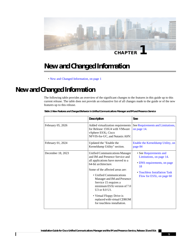
The following table provides an overview of the significant changes to the features in this guide up to this
current release. The table does not provide an exhaustive list of all changes made to the guide or of the new
features up to this release.
Table 1: New Features and Changed Behavior in Unified Communications Manager and IM and Presence Service
See
Description
See Requirements and Limitations,
on page 14.
Added virtualization requirements
for Release 15SU4 with VMware
vSphere ESXi, Cisco
NFVIS-for-UC, and Nutanix AHV.
February 05, 2026
Enable the Kerneldump Utility, on
page 84
Updated the "Enable the
Kerneldump Utility" section.
February 01, 2024
• See Requirements and
Limitations, on page 14.
• DNS requirements, on page
18
• Touchless Installation Task
Flow for ESXi, on page 60
Unified Communications Manager
and IM and Presence Service and
all applications have moved to a
64-bit architecture.
Some of the affected areas are:
• Unified Communications
Manager and IM and Presence
Service 15 requires a
minimum ESXi version of 7.0
U3 or 8.0 U1.
• Virtual Floppy Drive is
replaced with virtual CDROM
for touchless installation.
December 18, 2023
Installation Guide for Cisco Unified Communications Manager and the IM and Presence Service, Release 15 and SUs
1

Page 8
Installation Guide for Cisco Unified Communications Manager and the IM and Presence Service, Release 15 and SUs
2
New and Changed Information
New and Changed Information

Page 9
C H A P T E R 2
Planning the Installation
• Topology Options, on page 3
• Installation Methods, on page 6
• Requirements and Limitations, on page 14
• Licensing Requirements, on page 23
• Required Installation Information, on page 27
• Export Restricted and Export Unrestricted Software, on page 32
Topology Options
This section provides an overview of the system topology and describes the relationship between the types
of nodes in the topology.
Clusters
Clusters provide a mechanism for distributing call processing, presence status, and database replication across
multiple servers for scalability and redundancy. They provide transparent sharing of resources and features,
and enable system scalability.
A cluster comprises a set of Unified Communications Manager nodes and/or IM and Presence nodes that run
compatible software versions.
If you are deploying the IM and Presence Service, you must decide before you begin the installation whether
you want a Standard Deployment (IM and Presence Service on Unified Communications Manager) or an IM
and Presence Centralized Cluster Deployment. Both deployment options require sizing the IM and Presence
Service cluster(s) for all presence users across all telephony clusters in the deployment.
Installation Guide for Cisco Unified Communications Manager and the IM and Presence Service, Release 15 and SUs
3


Page 10
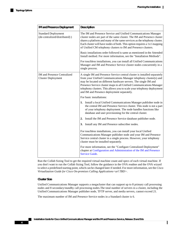
Description
IM and Presence Deployment
The IM and Presence Service and Unified Communications Manager
cluster nodes are part of the same cluster. The IM and Presence cluster
shares a platform and many of the same services as the telephony cluster.
Each cluster will have nodes of both. This option requires a 1x1 mapping
of Unified CM telephony clusters to IM and Presence clusters.
Basic installations order followed is same as mentioned in the Attended
Install method. For more information, see the "Installation Methods".
For touchless installations, you can install all Unified Communications
Manager and IM and Presence Service cluster nodes concurrently in a
single process.
Standard Deployment
(de-centralized/distributed) )
A single IM and Presence Service central cluster is installed separately
from your Unified Communications Manager telephony cluster(s) and
may be located on different hardware servers. The single IM and
Presence Service cluster maps to all Unified Communications Manager
telephony clusters. This allows you to scale your telephony deployment
and IM and Presence deployment separately.
For basic installations:
1.
Install a local Unified Communications Manager publisher node in
the central IM and Presence Service cluster. This node is not a part
of your telephony deployment. The node handles functions like
database and user provisioning for the central cluster.
2.
Install the IM and Presence Service database publisher node.
3.
Install any IM and Presence subscriber nodes.
For touchless installations, you can install your local Unified
Communications Manager publisher node and your IM and Presence
Service central cluster in a single process. However, your telephony
cluster must be installed separately.
For more information, see the "Configure Centralized Deployment"
chapter at Configuration and Administration of the IM and Presence
Service Guide.
IM and Presence Centralized
Cluster Deployment
Run the Collab Sizing Tool to get the required virtual machine count and specs of each virtual machine. If
you don't want to run the Collab Sizing Tool, follow the guidance in the OVA readme and the OVA wizard
to select a predefined starting point, which can be changed later if needed. For more information, see the Cisco
Virtualization Guide for Cisco On-premises Calling Applications<url TBD>.
Cluster Size
Unified Communications Manager supports a megacluster that can support up to 8 primary call processing
nodes and 8 secondary/standby call processing nodes.The total number of servers in a cluster, including the
Unified Communications Manager publisher node, TFTP server, and media servers, cannot exceed 21.
The maximum number of IM and Presence Service nodes in a Standard cluster is 6.
Installation Guide for Cisco Unified Communications Manager and the IM and Presence Service, Release 15 and SUs
4
Planning the Installation
Topology Options
Page 11
For more information, see "Cisco Collaboration Solutions Design Guidance" at http://www.cisco.com/go/
ucsrnd.
Publisher Nodes and Subscriber Nodes
Within a cluster, there is a database publisher for each type of node that you install.
When you install Unified Communications Manager, the installation wizard prompts you to specify whether
the node you are installing is the first node in the cluster. The first Unified Communications Manager node
that you install becomes the publisher node, because it publishes the voice and video database to the other
Unified Communications Manager nodes in the cluster. All subsequent nodes in the cluster are called subscriber
nodes. Each subscriber node must be associated with the publisher node. You must set up all subscriber nodes
in the system topology on the publisher node before you install the software on the subscriber nodes.
When you install IM and Presence nodes, the first node that you install functions as the server for the IM and
Presence database. Because this node publishes the database for all of the IM and Presence nodes in the cluster,
it is referred to as the IM and Presence database publisher; however, you must install this and all other IM
and Presence nodes as subscribers of the Unified Communications Manager publisher node. As with other
subscriber nodes, you must add these in the system topology before you install the software.
Topology Options
When installing your cluster, you must decide on the topology that you want to deploy. For example:
• The number of cluster nodes required.
• Whether you will install all cluster nodes in a single location, or if you will install your nodes in separate
geographic sites connected via a WAN in order to provide geographic redundancy. For more information
on scalability, see Megacluster.
Supported Versions for Intra-cluster versions
Unified Communications Manager and the IM and Presence Service nodes in the same cluster must be running
the supported builds as mentioned in the Release Notes for Cisco Unified Communications Manager and the
IM and Presence Service.
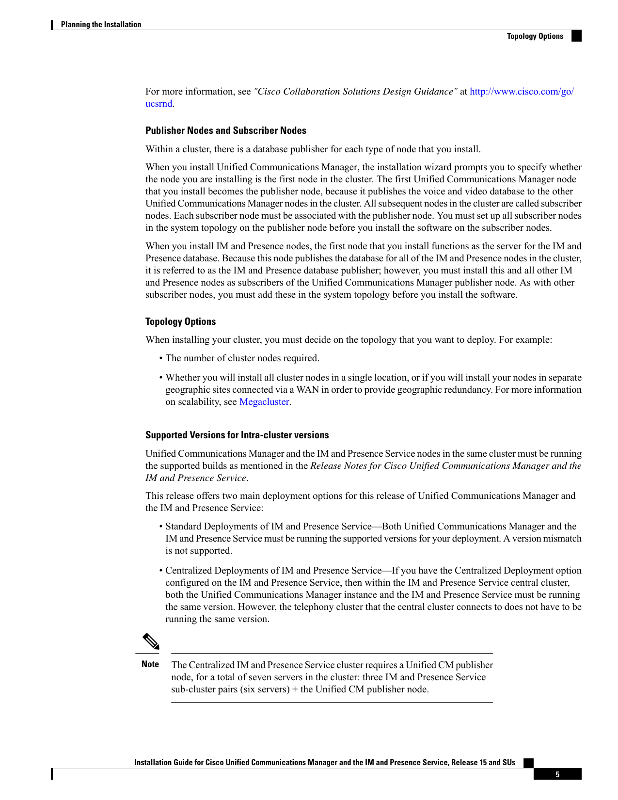
This release offers two main deployment options for this release of Unified Communications Manager and
the IM and Presence Service:
• Standard Deployments of IM and Presence Service—Both Unified Communications Manager and the
IM and Presence Service must be running the supported versions for your deployment. A version mismatch
is not supported.
• Centralized Deployments of IM and Presence Service—If you have the Centralized Deployment option
configured on the IM and Presence Service, then within the IM and Presence Service central cluster,
both the Unified Communications Manager instance and the IM and Presence Service must be running
the same version. However, the telephony cluster that the central cluster connects to does not have to be
running the same version.
The Centralized IM and Presence Service cluster requires a Unified CM publisher
node, for a total of seven servers in the cluster: three IM and Presence Service
sub-cluster pairs (six servers) + the Unified CM publisher node.
Note
Installation Guide for Cisco Unified Communications Manager and the IM and Presence Service, Release 15 and SUs
5
Planning the Installation
Topology Options

Page 12
Installation Methods
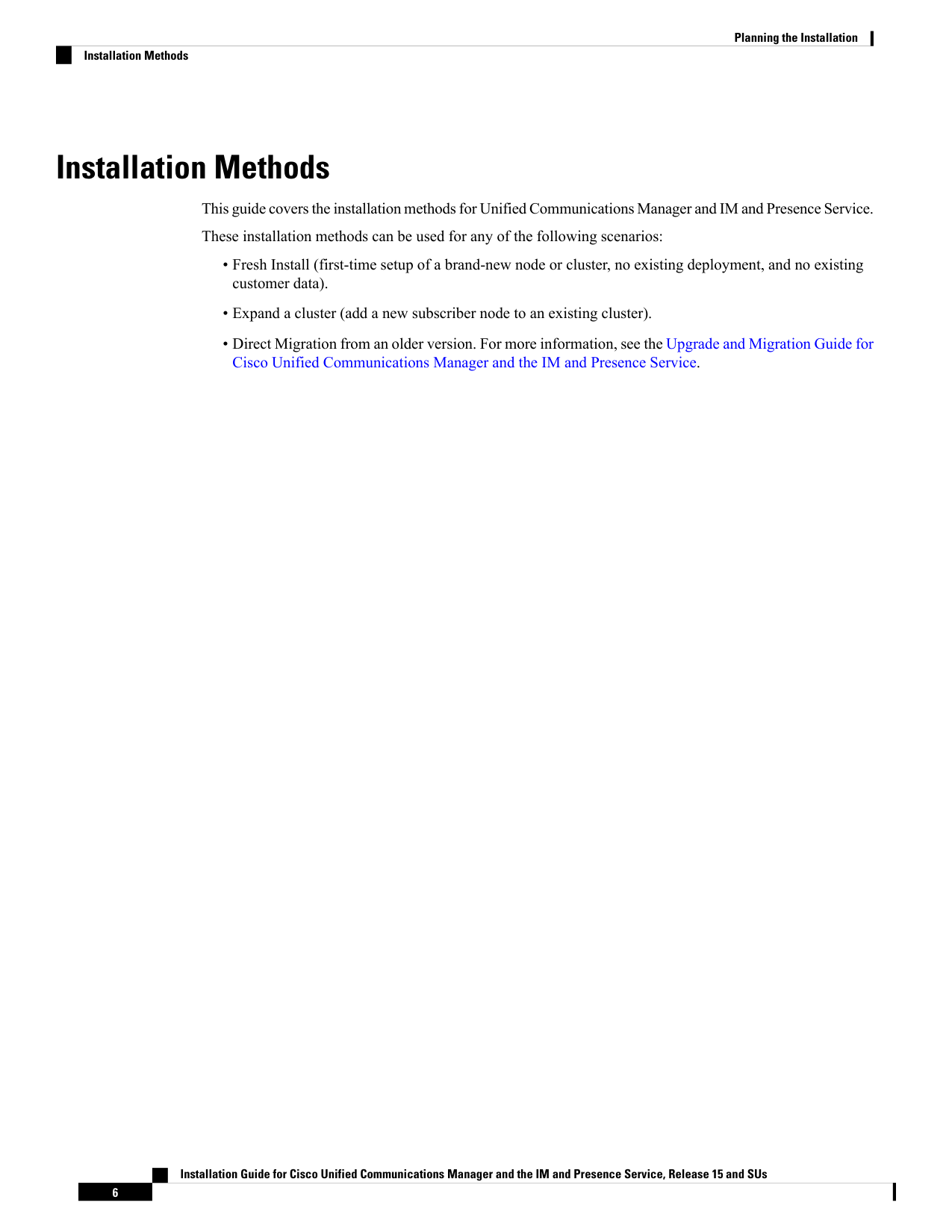
This guide covers the installation methods for Unified Communications Manager and IM and Presence Service.
These installation methods can be used for any of the following scenarios:
• Fresh Install (first-time setup of a brand-new node or cluster, no existing deployment, and no existing
customer data).
• Expand a cluster (add a new subscriber node to an existing cluster).
• Direct Migration from an older version. For more information, see the Upgrade and Migration Guide for
Cisco Unified Communications Manager and the IM and Presence Service.
Installation Guide for Cisco Unified Communications Manager and the IM and Presence Service, Release 15 and SUs
6
Planning the Installation
Installation Methods
Page 13
Description
Installation Method
Attended Install
Installation Guide for Cisco Unified Communications Manager and the IM and Presence Service, Release 15 and SUs
7
Planning the Installation
Installation Methods

Page 14
Description
Installation Method
Note
This installation method is applicable for VMware
vSphere ESXi, Nutanix AHV, and Cisco
NFVIS-for-UC.
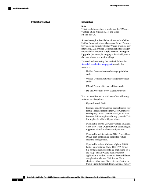
A baseline-typical installation of one node of either
Unified Communications Manager or IM and Presence
Service, using the native Install Wizard graphical user
interface (GUI). Unified Communications Manager
only includes an option Apply a Patch During an
Upgrade (for example, to apply a Service Update to
the base release you are installing).
To install a cluster using this method, follow the
Attended Installation, on page 48 steps in this
sequence:
• Unified Communications Manager publisher
node
• Unified Communications Manager subscriber
nodes
• IM and Presence Service publisher node
• IM and Presence Service subscriber nodes
You can use this method with any of the following
software media options:
• Physical install DVD.
• Bootable installer image for base release in ISO
format (obtained from either Cisco Commerce
Workspace, Cisco License Central, or a Cisco
Business Edition appliance factory preload). This
file applies for all the 3 hypervisors.
• (Applicable only to VMware vSphere ESXi and
Cisco NFVIS for UC) Base OVA containing all
supported virtual machine configurations.
• (Applicable only to Nutanix AHV) A set of base
OVAs, each containing a supported virtual
machine configuration.
• (Applicable only to VMware vSphere ESXi)
Partial skip-installed OVA. This OVA format
file contains partially installed application up to
the "skip" Install Wizard point where the
application is ready to accept an Answer File and
complete installation. OVA format file is
obtained either from Cisco License Central or
from a Cisco Business Edition appliance factory
Installation Guide for Cisco Unified Communications Manager and the IM and Presence Service, Release 15 and SUs
8
Planning the Installation
Installation Methods
Page 15
Description
Installation Method
preload.
Note
Use this method when manual installation without
automation is acceptable, such as labs or small
deployments.
Installation Guide for Cisco Unified Communications Manager and the IM and Presence Service, Release 15 and SUs
9
Planning the Installation
Installation Methods

Page 16
Description
Installation Method
Note
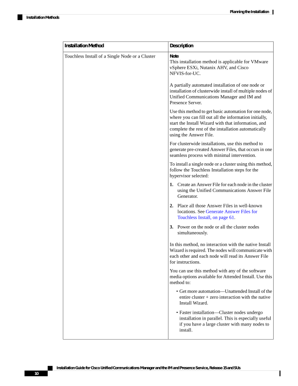
This installation method is applicable for VMware
vSphere ESXi, Nutanix AHV, and Cisco
NFVIS-for-UC.
A partially automated installation of one node or
installation of clusterwide install of multiple nodes of
Unified Communications Manager and IM and
Presence Server.
Use this method to get basic automation for one node,
where you can fill out all the information initially,
start the Install Wizard with that information, and
complete the rest of the installation automatically
using the Answer File.
For clusterwide installations, use this method to
generate pre-created Answer Files, that occurs in one
seamless process with minimal intervention.
To install a single node or a cluster using this method,
follow the Touchless Installation steps for the
hypervisor selected:
1.
Create an Answer File for each node in the cluster
using the Unified Communications Answer File
Generator.
2.
Place all those Answer Files in well-known
locations. See Generate Answer Files for
Touchless Install, on page 61.
3.
Power on the node or all the cluster nodes
simultaneously.
In this method, no interaction with the native Install
Wizard is required. The nodes will communicate with
each other and each node will read its Answer File
for instructions.
You can use this method with any of the software
media options available for Attended Install. Use this
method to:
• Get more automation—Unattended Install of the
entire cluster + zero interaction with the native
Install Wizard.
• Faster installation—Cluster nodes undergo
installation in parallel. This is especially useful
if you have a large cluster with many nodes to
install.
Touchless Install of a Single Node or a Cluster
Installation Guide for Cisco Unified Communications Manager and the IM and Presence Service, Release 15 and SUs
10
Planning the Installation
Installation Methods
Page 17
Description
Installation Method
Note
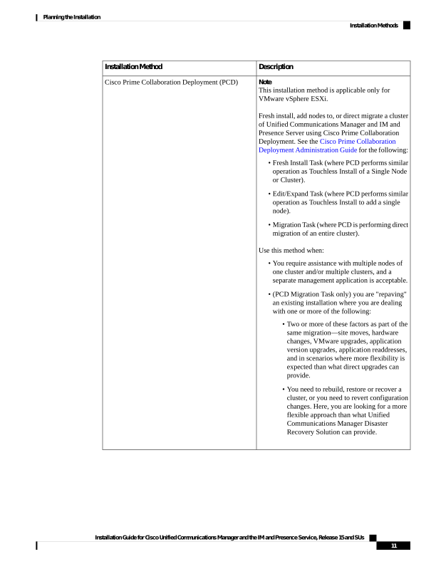
This installation method is applicable only for
VMware vSphere ESXi.
Fresh install, add nodes to, or direct migrate a cluster
of Unified Communications Manager and IM and
Presence Server using Cisco Prime Collaboration
Deployment. See the Cisco Prime Collaboration
Deployment Administration Guide for the following:
• Fresh Install Task (where PCD performs similar
operation as Touchless Install of a Single Node
or Cluster).
• Edit/Expand Task (where PCD performs similar
operation as Touchless Install to add a single
node).
• Migration Task (where PCD is performing direct
migration of an entire cluster).
Use this method when:
• You require assistance with multiple nodes of
one cluster and/or multiple clusters, and a
separate management application is acceptable.
• (PCD Migration Task only) you are "repaving"
an existing installation where you are dealing
with one or more of the following:
• Two or more of these factors as part of the
same migration—site moves, hardware
changes, VMware upgrades, application
version upgrades, application readdresses,
and in scenarios where more flexibility is
expected than what direct upgrades can
provide.
• You need to rebuild, restore or recover a
cluster, or you need to revert configuration
changes. Here, you are looking for a more
flexible approach than what Unified
Communications Manager Disaster
Recovery Solution can provide.
Cisco Prime Collaboration Deployment (PCD)
Installation Guide for Cisco Unified Communications Manager and the IM and Presence Service, Release 15 and SUs
11
Planning the Installation
Installation Methods
Page 18
Description
Installation Method
Note
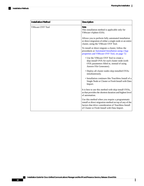
This installation method is applicable only for
VMware vSphere ESXi.
Allows you to perform fully automated installation
or direct migration of either a single node or an entire
cluster, using the VMware OVF Tool.
To install or direct migrate a cluster, follow the
procedures at Automated Installation using vApp
properties and VMware OVF Tool, on page 72:
• Use the VMware OVF Tool to create a
skip-install OVA for each cluster node (with
OVA parameters filled in, instead of using
Answer File Generator).
• Deploy all cluster nodes skip-installed OVAs
simultaneously.
• Installation continues like Touchless Install of a
Single Node or Cluster or Fresh Install with Data
Import.
It is best to use this method with skip-install OVAs,
as that provides the shortest duration and highest level
of automation.
Use this method when you require a programmatic
install or direct migration method on top of any of the
factors that drive consideration of Touchless Install
of Cluster or Fresh Install with Data Import.
VMware OVF Tool
Installation Guide for Cisco Unified Communications Manager and the IM and Presence Service, Release 15 and SUs
12
Planning the Installation
Installation Methods
Page 19
Description
Installation Method
Note
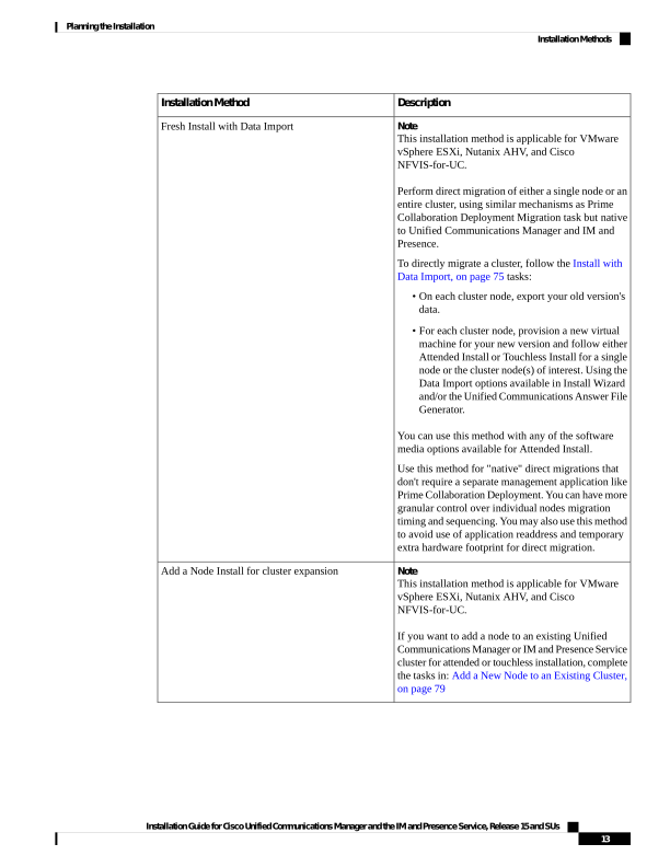
This installation method is applicable for VMware
vSphere ESXi, Nutanix AHV, and Cisco
NFVIS-for-UC.
Perform direct migration of either a single node or an
entire cluster, using similar mechanisms as Prime
Collaboration Deployment Migration task but native
to Unified Communications Manager and IM and
Presence.
To directly migrate a cluster, follow the Install with
Data Import, on page 75 tasks:
• On each cluster node, export your old version's
data.
• For each cluster node, provision a new virtual
machine for your new version and follow either
Attended Install or Touchless Install for a single
node or the cluster node(s) of interest. Using the
Data Import options available in Install Wizard
and/or the Unified Communications Answer File
Generator.
You can use this method with any of the software
media options available for Attended Install.
Use this method for "native" direct migrations that
don't require a separate management application like
Prime Collaboration Deployment. You can have more
granular control over individual nodes migration
timing and sequencing. You may also use this method
to avoid use of application readdress and temporary
extra hardware footprint for direct migration.
Fresh Install with Data Import
Note
This installation method is applicable for VMware
vSphere ESXi, Nutanix AHV, and Cisco
NFVIS-for-UC.
If you want to add a node to an existing Unified
Communications Manager or IM and Presence Service
cluster for attended or touchless installation, complete
the tasks in: Add a New Node to an Existing Cluster,
on page 79
Add a Node Install for cluster expansion
Installation Guide for Cisco Unified Communications Manager and the IM and Presence Service, Release 15 and SUs
13
Planning the Installation
Installation Methods
Page 20
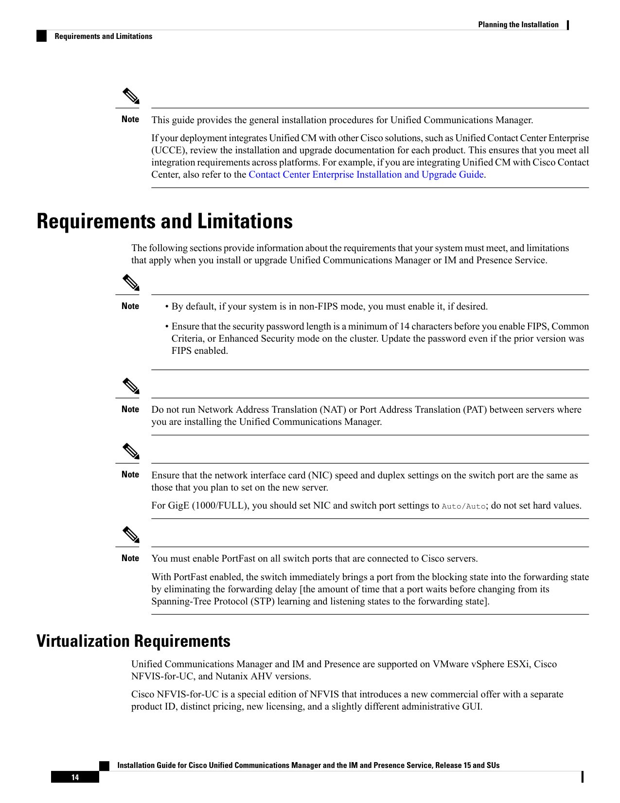
This guide provides the general installation procedures for Unified Communications Manager.
If your deployment integrates Unified CM with other Cisco solutions, such as Unified Contact Center Enterprise
(UCCE), review the installation and upgrade documentation for each product. This ensures that you meet all
integration requirements across platforms. For example, if you are integrating Unified CM with Cisco Contact
Center, also refer to the Contact Center Enterprise Installation and Upgrade Guide.
Note
Requirements and Limitations
The following sections provide information about the requirements that your system must meet, and limitations
that apply when you install or upgrade Unified Communications Manager or IM and Presence Service.
• By default, if your system is in non-FIPS mode, you must enable it, if desired.
• Ensure that the security password length is a minimum of 14 characters before you enable FIPS, Common
Criteria, or Enhanced Security mode on the cluster. Update the password even if the prior version was
FIPS enabled.
Note
Do not run Network Address Translation (NAT) or Port Address Translation (PAT) between servers where
you are installing the Unified Communications Manager.
Note
Ensure that the network interface card (NIC) speed and duplex settings on the switch port are the same as
those that you plan to set on the new server.
For GigE (1000/FULL), you should set NIC and switch port settings to Auto/Auto; do not set hard values.
Note
You must enable PortFast on all switch ports that are connected to Cisco servers.
With PortFast enabled, the switch immediately brings a port from the blocking state into the forwarding state
by eliminating the forwarding delay [the amount of time that a port waits before changing from its
Spanning-Tree Protocol (STP) learning and listening states to the forwarding state].
Note
Virtualization Requirements
Unified Communications Manager and IM and Presence are supported on VMware vSphere ESXi, Cisco
NFVIS-for-UC, and Nutanix AHV versions.
Cisco NFVIS-for-UC is a special edition of NFVIS that introduces a new commercial offer with a separate
product ID, distinct pricing, new licensing, and a slightly different administrative GUI.
Installation Guide for Cisco Unified Communications Manager and the IM and Presence Service, Release 15 and SUs
14
Planning the Installation
Requirements and Limitations

Page 21
• Cisco NFVIS-for-UC supports only select on-premises calling applications.
• Cisco NFVIS-for-UC supports only select Cisco Calling Appliances.
For general virtualization software/hardware requirements, see the Cisco Virtualization Guide for Cisco
On-premises Calling Applications.
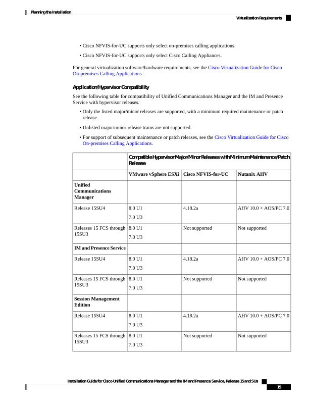
Application/Hypervisor Compatibility
See the following table for compatibility of Unified Communications Manager and the IM and Presence
Service with hypervisor releases.
• Only the listed major/minor releases are supported, with a minimum required maintenance or patch
release.
• Unlisted major/minor release trains are not supported.
• For support of subsequent maintenance or patch releases, see the Cisco Virtualization Guide for Cisco
On-premises Calling Applications.
CompatibleHypervisorMajor/MinorReleaseswithMinimumMaintenance/Patch
Release
Nutanix AHV
Cisco NFVIS-for-UC
VMware vSphere ESXi
Unified
Communications
Manager
AHV 10.0 + AOS/PC 7.0
4.18.2a
8.0 U1
7.0 U3
Release 15SU4
Not supported
Not supported
8.0 U1
7.0 U3
Releases 15 FCS through
15SU3
IM and Presence Service
AHV 10.0 + AOS/PC 7.0
4.18.2a
8.0 U1
7.0 U3
Release 15SU4
Not supported
Not supported
8.0 U1
7.0 U3
Releases 15 FCS through
15SU3
Session Management
Edition
AHV 10.0 + AOS/PC 7.0
4.18.2a
8.0 U1
7.0 U3
Release 15SU4
Not supported
Not supported
8.0 U1
7.0 U3
Releases 15 FCS through
15SU3
Installation Guide for Cisco Unified Communications Manager and the IM and Presence Service, Release 15 and SUs
15
Planning the Installation
Virtualization Requirements
Page 22
Virtual Machine Configurations and CPU Minimum Base Frequencies
Applications are supported only with specific virtual machine (VM) configurations.
You must deploy these VMs using the latest Cisco-provided OVA file (see the Readme file for important
notes.)
• For Unified Communications Manager nodes, the files are available here: https://software.cisco.com/
download/home/286331940/type/283088407/release/15
• For IM and Presence nodes, the files are available here: https://software.cisco.com/download/home/
286331963/type/283757588/release/15
• One base OVA is used for both VMware vSphere ESXi and Cisco NFVIS for UC, while a set of base
OVAs is used for Nutanix AHV.
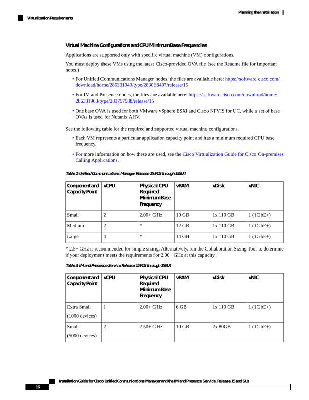
See the following table for the required and supported virtual machine configurations.
• Each VM represents a particular application capacity point and has a minimum required CPU base
frequency.
• For more information on how these are used, see the Cisco Virtualization Guide for Cisco On-premises
Calling Applications.
Table 2: Unified Communications Manager Release 15 FCS through 15SU4
vNIC
vDisk
vRAM
Physical CPU
Required
Minimum Base
Frequency
vCPU
Component and
Capacity Point
1 (1GbE+)
1x 110 GB
10 GB
2.00+ GHz
2
Small
1 (1GbE+)
1x 110 GB
12 GB
*
2
Medium
1 (1GbE+)
1x 110 GB
14 GB
*
4
Large
- 2.5+ GHz is recommended for simple sizing. Alternatively, run the Collaboration Sizing Tool to determine
if your deployment meets the requirements for 2.00+ GHz at this capacity.
Table 3: IM and Presence Service Release 15 FCS through 15SU4
vNIC
vDisk
vRAM
Physical CPU
Required
Minimum Base
Frequency
vCPU
Component and
Capacity Point
1 (1GbE+)
1x 110 GB
6 GB
2.00+ GHz
1
Extra Small
(1000 devices)
1 (1GbE+)
2x 80GB
10 GB
2.50+ GHz
2
Small
(5000 devices)
Installation Guide for Cisco Unified Communications Manager and the IM and Presence Service, Release 15 and SUs
16
Planning the Installation
Virtualization Requirements
Page 23
vNIC
vDisk
vRAM
Physical CPU
Required
Minimum Base
Frequency
vCPU
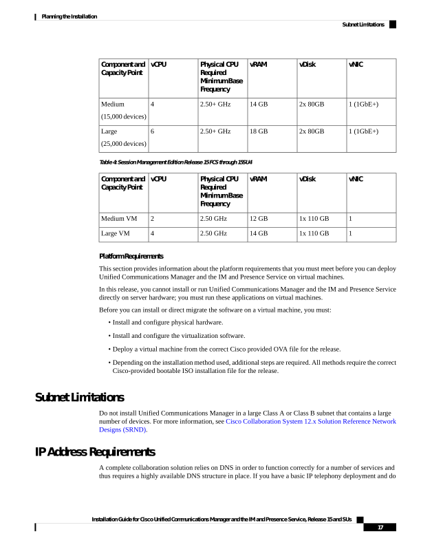
Component and
Capacity Point
1 (1GbE+)
2x 80GB
14 GB
2.50+ GHz
4
Medium
(15,000 devices)
1 (1GbE+)
2x 80GB
18 GB
2.50+ GHz
6
Large
(25,000 devices)
Table 4: Session Management Edition Release 15 FCS through 15SU4
vNIC
vDisk
vRAM
Physical CPU
Required
Minimum Base
Frequency
vCPU
Component and
Capacity Point
1
1x 110 GB
12 GB
2.50 GHz
2
Medium VM
1
1x 110 GB
14 GB
2.50 GHz
4
Large VM
Platform Requirements
This section provides information about the platform requirements that you must meet before you can deploy
Unified Communications Manager and the IM and Presence Service on virtual machines.
In this release, you cannot install or run Unified Communications Manager and the IM and Presence Service
directly on server hardware; you must run these applications on virtual machines.
Before you can install or direct migrate the software on a virtual machine, you must:
• Install and configure physical hardware.
• Install and configure the virtualization software.
• Deploy a virtual machine from the correct Cisco provided OVA file for the release.
• Depending on the installation method used, additional steps are required. All methods require the correct
Cisco-provided bootable ISO installation file for the release.
Subnet Limitations
Do not install Unified Communications Manager in a large Class A or Class B subnet that contains a large
number of devices. For more information, see Cisco Collaboration System 12.x Solution Reference Network
Designs (SRND).
IP Address Requirements
A complete collaboration solution relies on DNS in order to function correctly for a number of services and
thus requires a highly available DNS structure in place. If you have a basic IP telephony deployment and do
Installation Guide for Cisco Unified Communications Manager and the IM and Presence Service, Release 15 and SUs
17
Planning the Installation
Subnet Limitations
Page 24
not want to use DNS, you can configure Unified Communications Manager and IM and Presence Service to
use IP addresses rather than hostnames to communicate with gateways and endpoint devices.
You must configure the server to use static IP addressing to ensure that the server obtains a fixed IP address.
Using a static IP address also ensures that Cisco Unified IP Phones can register with the application when
you plug the phones into the network.
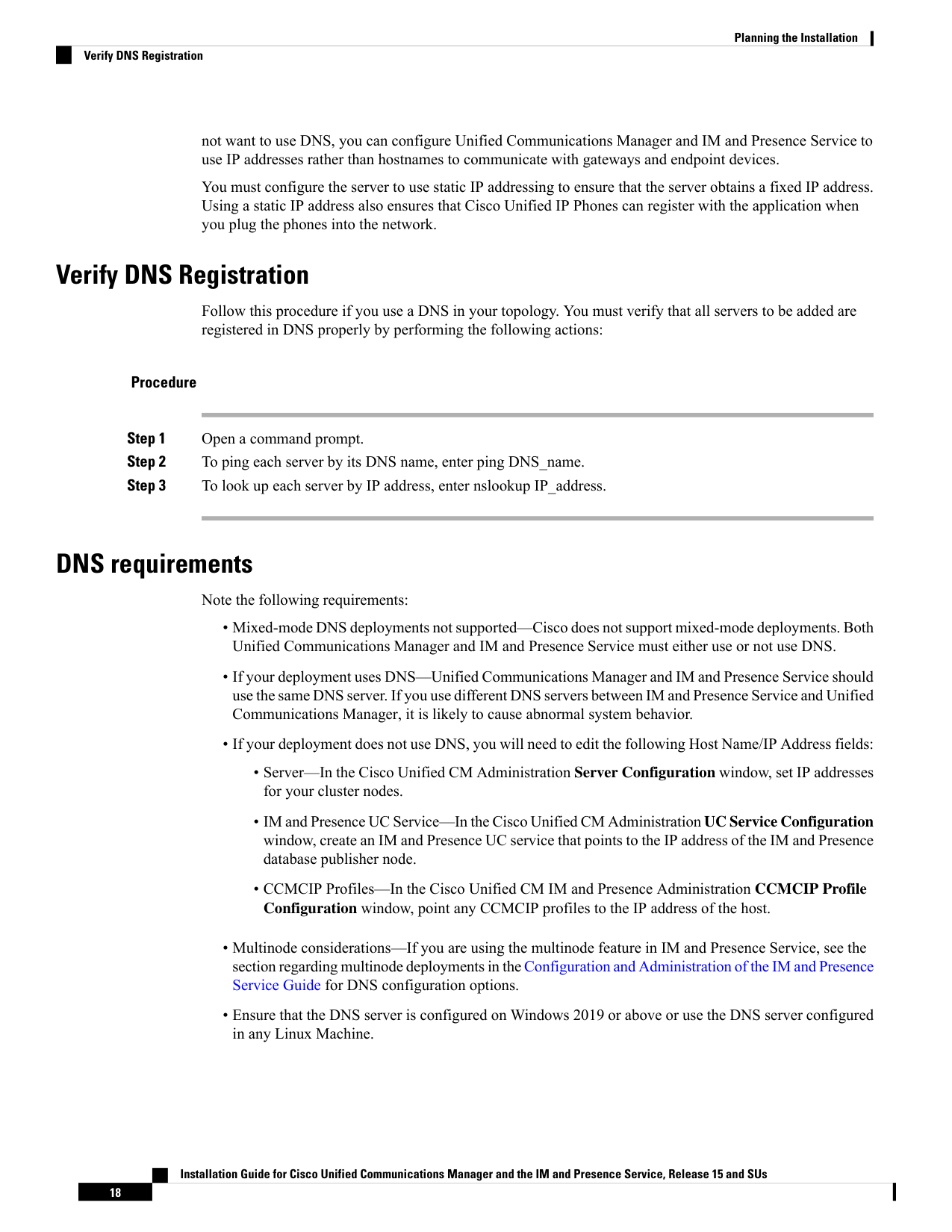
Verify DNS Registration
Follow this procedure if you use a DNS in your topology. You must verify that all servers to be added are
registered in DNS properly by performing the following actions:
Procedure
Step 1
Open a command prompt.
Step 2
To ping each server by its DNS name, enter ping DNS_name.
Step 3
To look up each server by IP address, enter nslookup IP_address.
DNS requirements
Note the following requirements:
• Mixed-mode DNS deployments not supported—Cisco does not support mixed-mode deployments. Both
Unified Communications Manager and IM and Presence Service must either use or not use DNS.
• If your deployment uses DNS—Unified Communications Manager and IM and Presence Service should
use the same DNS server. If you use different DNS servers between IM and Presence Service and Unified
Communications Manager, it is likely to cause abnormal system behavior.
• If your deployment does not use DNS, you will need to edit the following Host Name/IP Address fields:
• Server—In the Cisco Unified CM Administration Server Configuration window, set IP addresses
for your cluster nodes.
• IM and Presence UC Service—In the Cisco Unified CM Administration UC Service Configuration
window, create an IM and Presence UC service that points to the IP address of the IM and Presence
database publisher node.
• CCMCIP Profiles—In the Cisco Unified CM IM and Presence Administration CCMCIP Profile
Configuration window, point any CCMCIP profiles to the IP address of the host.
• Multinode considerations—If you are using the multinode feature in IM and Presence Service, see the
section regarding multinode deployments in the Configuration and Administration of the IM and Presence
Service Guide for DNS configuration options.
• Ensure that the DNS server is configured on Windows 2019 or above or use the DNS server configured
in any Linux Machine.
Installation Guide for Cisco Unified Communications Manager and the IM and Presence Service, Release 15 and SUs
18
Planning the Installation
Verify DNS Registration
Page 25
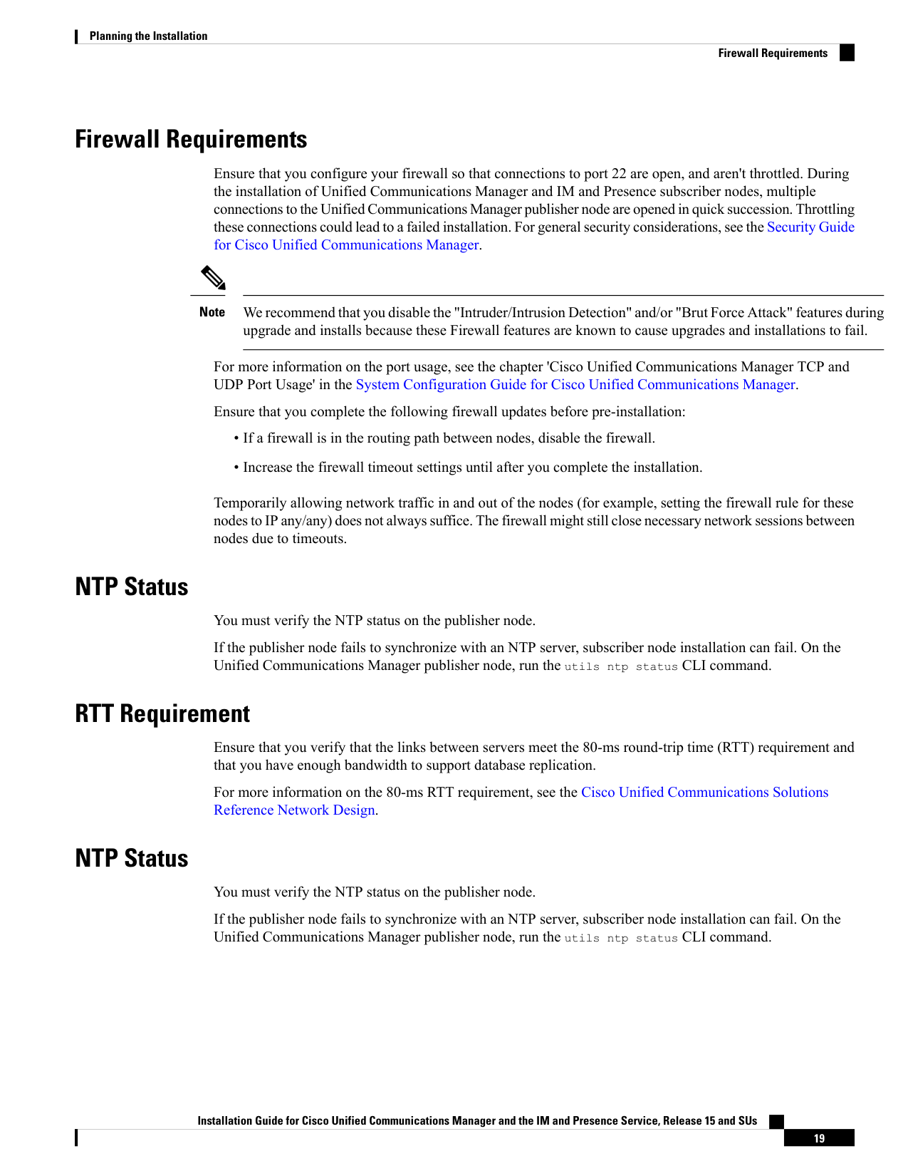
Firewall Requirements
Ensure that you configure your firewall so that connections to port 22 are open, and aren't throttled. During
the installation of Unified Communications Manager and IM and Presence subscriber nodes, multiple
connections to the Unified Communications Manager publisher node are opened in quick succession. Throttling
these connections could lead to a failed installation. For general security considerations, see the Security Guide
for Cisco Unified Communications Manager.
We recommend that you disable the "Intruder/Intrusion Detection" and/or "Brut Force Attack" features during
upgrade and installs because these Firewall features are known to cause upgrades and installations to fail.
Note
For more information on the port usage, see the chapter 'Cisco Unified Communications Manager TCP and
UDP Port Usage' in the System Configuration Guide for Cisco Unified Communications Manager.
Ensure that you complete the following firewall updates before pre-installation:
• If a firewall is in the routing path between nodes, disable the firewall.
• Increase the firewall timeout settings until after you complete the installation.
Temporarily allowing network traffic in and out of the nodes (for example, setting the firewall rule for these
nodes to IP any/any) does not always suffice. The firewall might still close necessary network sessions between
nodes due to timeouts.
NTP Status
You must verify the NTP status on the publisher node.
If the publisher node fails to synchronize with an NTP server, subscriber node installation can fail. On the
Unified Communications Manager publisher node, run the utils ntp status CLI command.
RTT Requirement
Ensure that you verify that the links between servers meet the 80-ms round-trip time (RTT) requirement and
that you have enough bandwidth to support database replication.
For more information on the 80-ms RTT requirement, see the Cisco Unified Communications Solutions
Reference Network Design.
NTP Status
You must verify the NTP status on the publisher node.
If the publisher node fails to synchronize with an NTP server, subscriber node installation can fail. On the
Unified Communications Manager publisher node, run the utils ntp status CLI command.
Installation Guide for Cisco Unified Communications Manager and the IM and Presence Service, Release 15 and SUs
19
Planning the Installation
Firewall Requirements

Page 26
Supported Versions
Unified Communications Manager and the IM and Presence Service nodes in the same cluster must be running
the supported builds as mentioned in the Release Notes for Cisco Unified Communications Manager and the
IM and Presence Service.
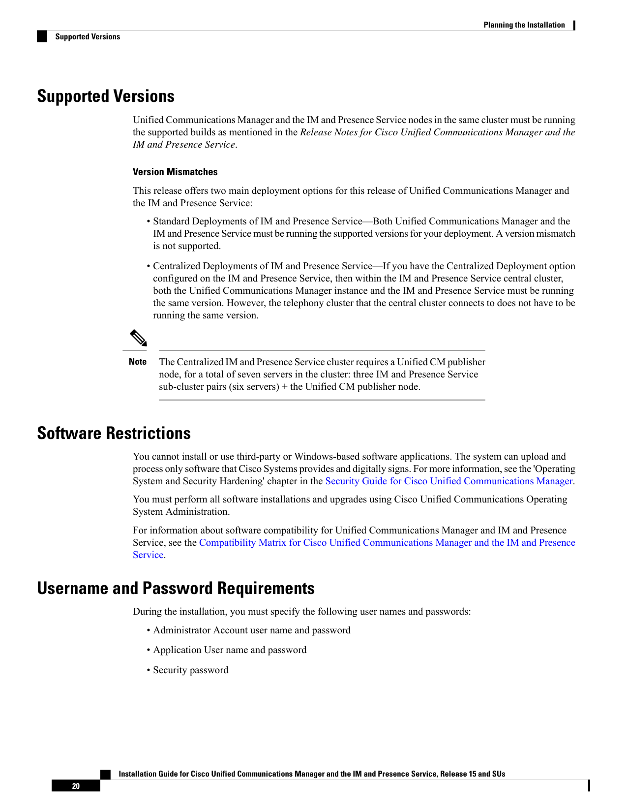
Version Mismatches
This release offers two main deployment options for this release of Unified Communications Manager and
the IM and Presence Service:
• Standard Deployments of IM and Presence Service—Both Unified Communications Manager and the
IM and Presence Service must be running the supported versions for your deployment. A version mismatch
is not supported.
• Centralized Deployments of IM and Presence Service—If you have the Centralized Deployment option
configured on the IM and Presence Service, then within the IM and Presence Service central cluster,
both the Unified Communications Manager instance and the IM and Presence Service must be running
the same version. However, the telephony cluster that the central cluster connects to does not have to be
running the same version.
The Centralized IM and Presence Service cluster requires a Unified CM publisher
node, for a total of seven servers in the cluster: three IM and Presence Service
sub-cluster pairs (six servers) + the Unified CM publisher node.
Note
Software Restrictions
You cannot install or use third-party or Windows-based software applications. The system can upload and
process only software that Cisco Systems provides and digitally signs. For more information, see the 'Operating
System and Security Hardening' chapter in the Security Guide for Cisco Unified Communications Manager.
You must perform all software installations and upgrades using Cisco Unified Communications Operating
System Administration.
For information about software compatibility for Unified Communications Manager and IM and Presence
Service, see the Compatibility Matrix for Cisco Unified Communications Manager and the IM and Presence
Service.
Username and Password Requirements
During the installation, you must specify the following user names and passwords:
• Administrator Account user name and password
• Application User name and password
• Security password
Installation Guide for Cisco Unified Communications Manager and the IM and Presence Service, Release 15 and SUs
20
Planning the Installation
Supported Versions

Page 27
We recommend that you use a different username for the Cisco Unified Communications Operating System
Administration and the Cisco Unified CM Administration interfaces.
Note
Administrator Account
You use the Administrator Account user name and password to log in to the following areas:
• Cisco Unified Communications Operating System Administration
• Disaster Recovery System
• Command Line Interface
To specify the Administrator Account user name and password, follow these guidelines:
• Administrator Account user name—The Administrator Account user name must start with an alphabetic
character and can contain alphanumeric characters, hyphens, and underscores.
• Administrator Account password—The Administrator Account password must be at least eight characters
long and can contain alphanumeric characters, hyphens, and underscores.
You can change the Administrator Account password or add a new Administrator account by using the
command line interface. For more information, see the Command Line Interface Reference Guide for Cisco
Unified Communications Solutions.
Application User
When you install Unified Communications Manager, you must enter an Application User name and password.
You use the Application User name and password to access applications that are installed on the system,
including the following areas:
• Cisco Unified CM Administration
• Cisco Unified Serviceability
• Cisco Real-Time Monitoring Tool
• Cisco Unified Reporting
To specify the Application User name and password, follow these guidelines:
• Application User username—The Application User username must start with an alphabetic character
and can contain alphanumeric characters, hyphens, and underscores.
• Application User password—The Application User password must be at least eight characters long and
can contain alphanumeric characters, hyphens, and underscores.
Installation Guide for Cisco Unified Communications Manager and the IM and Presence Service, Release 15 and SUs
21
Planning the Installation
Username and Password Requirements

Page 28
Do not use the system application name as the Application User name. Using a system application name
causes the installation to fail with an unrecoverable error during the installation of the database.
System application names are:
• CCMSysUser
• WDSysUser
• CCMQRTSysUser
• IPMASysUser
• WDSecureSysUser
• CCMQRTSecureSysUser
• IPMASecureSysUser
• TabSyncSysUser
• CUCService
Caution
You can change the Application User name and password by using the command line interface. For more
information, see the Command Line Interface Reference Guide for Cisco Unified Communications Solutions.
Security Password
During the installation, you must specify a security password. Unified Communications Manager systems
use this password to authorize communications between nodes in the cluster, including IM and Presence
Service nodes. This password must be identical on all nodes in the cluster.
The Security password must be at least eight characters long and can contain alphanumeric characters, hyphens,
and underscores.
Password Recommendations
The installation wizard ensures that you enter a strong password. To create a strong password, follow these
recommendations:
• Password must be at least eight characters long and can contain alphanumeric characters, hyphens, and
underscore.
If you plan to enable FIPS, Common Criteria, or Enhanced Security mode on any
cluster, you must ensure that the security password is at least 14 characters long.
Note
• Should not have the non-printable ASCII characters.
• Contains at least one alphanumeric character.
• Mix uppercase and lowercase letters.
• Mix letters and numbers.
Installation Guide for Cisco Unified Communications Manager and the IM and Presence Service, Release 15 and SUs
22
Planning the Installation
Password Recommendations


Page 29
• Include special symbols.
• Remember that longer passwords are stronger and more secure than shorter ones.
Avoid the following types of passwords:
• Do not use only alphanumeric characters.
• Do not use any non-alphanumeric characters.
• Do not use recognizable words, such as proper names and dictionary words, even when combined with
numbers.
• Do not invert-recognizable words.
• Do not use word or number patterns, such as aaabbb, abc123, qwerty, zyxwvuts, and 123321.
• Do not use recognizable words from other languages.
• Do not use personal information of any kind, including birthdays, postal codes, names of children, or
pets.
Installation Time Requirements
Time Requirements for Unified Communications Manager
The entire installation process, excluding pre- and post-installation tasks, takes 45 to 90 minutes, depending
on your server type.
Time Requirements for IM and Presence Nodes
The entire IM and Presence Service installation process, excluding pre- and post-installation tasks, takes
approximately 45 to 90 minutes per server, depending on your server type.
Licensing Requirements
The following sections provide information about the licensing requirements for Unified Communications
Manager and the IM and Presence Service.
Make sure that your system has adequate licensing.
Smart Software Licensing Overview
Cisco Smart Software Licensing is a new way of thinking about licensing. It adds flexibility to your licensing
and simplifies it across the enterprise. It also delivers visibility into your license ownership and consumption.
Cisco Smart Software Licensing helps you to procure, deploy, and manage licenses easily where devices
self-register and report license consumption, removing the need for product activation keys (PAK). It pools
license entitlements in a single account and allows you to move licenses freely through the network, wherever
you need them. It is enabled across Cisco products and managed by a direct cloud-based or mediated deployment
model.
Installation Guide for Cisco Unified Communications Manager and the IM and Presence Service, Release 15 and SUs
23
Planning the Installation
Installation Time Requirements
Page 30
The Cisco Smart Software Licensing service registers the product instance, reports license usage, and obtains
the necessary authorization from Cisco Smart Software Manager or Cisco Smart Software Manager satellite.
You can use Smart Licensing to:
• See the license usage and count
• See the status of each license type
• See the product licenses available on Cisco Smart Software Manager or Cisco Smart Software Manager
satellite
• Renew License Authorization with Cisco Smart Software Manager or Cisco Smart Software Manager
satellite
• Renew the License Registration
• Deregister with Cisco Smart Software Manager or Cisco Smart Software Manager satellite
The License authorization is valid for 90 days with a renewal at least once in 30 days. The authorization will
expire after 90 days if it is not connected to Cisco Smart Software Manager or Cisco Smart Software Manager
satellite.
If the Cisco Smart Software Manager satellite option is selected, the satellite must have an internet connection
to Cisco Smart Software Manager for the authorization to occur. The Cisco Smart Software Manager satellite
can operate in 2 modes: Connected Mode in which the connection time is configurable, and Disconnected
mode which requires a manual sync.
Note
There are two main deployment options for Smart Licensing:
• Cisco Smart Software Manager
• Cisco Smart Software Manager satellite
Cisco Smart Software Manager
The Cisco Smart Software Manager is a cloud-based service that handles your system licensing. Use this
option if Unified Communications Manager can connect to cisco.com, either directly or via a proxy server.
Cisco Smart Software Manager allows you to:
• Manage and track licenses
• Move licenses across virtual account
• Remove registered product instance
Optionally, if Unified Communications Manager cannot connect directly to Cisco Smart Software Manager,
you can deploy a proxy server to manage the connection.
Installation Guide for Cisco Unified Communications Manager and the IM and Presence Service, Release 15 and SUs
24
Planning the Installation
Smart Software Licensing Overview

Page 31
If you are upgrading Unified Communications Manager registered to Cisco Smart Software Manager from
Pre-15 releases to Release 15 or higher, Cisco Unified Communications Manager will not update the product
version to 15 in the Cisco Smart Software Manager UI for the Product Instance. Refer to CSCwf94088 for
more details.
Note
For additional information about Cisco Smart Software Manager, go to https://software.cisco.com.
Cisco Smart Software Manager Satellite
Cisco Smart Software Manager satellite is an on-premise deployment that can handle your licensing needs if
Unified Communications Manager cannot connect to cisco.com directly, either for security or availability
reasons. When this option is deployed, Unified Communications Manager registers and report license
consumption to the satellite, which synchronizes its database regularly with the backend Cisco Smart Software
Manager that is hosted on cisco.com.
The Cisco Smart Software Manager satellite can be deployed in either Connected or Disconnected mode,
depending on whether the satellite can connect directly to cisco.com.
• Connected—Used when there is connectivity to cisco.com directly from the Smart Software Manager
satellite. Smart account synchronization occurs automatically.
• Disconnected—Used when there is no connectivity to cisco.com from the Smart Software Manager
satellite. Smart Account synchronization must be manually uploaded and downloaded.
If you are upgrading Unified Communications Manager registered to Cisco Smart Software Manager Satellite
from Pre-15 releases to Release 15 or higher, Cisco Unified Communications Manager will not update the
product version to 15 in the Cisco Smart Software Manager UI for the Product Instance. Refer to CSCwf94088
for more details.
Note
For Cisco Smart Software Manager satellite information and documentation, go to https://www.cisco.com/c/
en/us/buy/smart-accounts/software-manager-satellite.html.
License Types
The following licensing types are available to cover your needs:
Cisco Unified Workspace Licensing
Cisco Unified Workspace Licensing (UWL) provides the most popular bundles of Cisco Collaboration
applications and services in a cost-effective, simple package. It includes soft clients, applications server
software, and licensing on a per-user basis.
Cisco User Connect Licensing
User Connect Licensing (UCL) is a per-user based license for individual Cisco Unified Communications
applications, which includes the applications server software, user licensing, and a soft client. Depending
on the type of device and number of devices that you require, UCL is available in Essential, Basic,
Enhanced, and Enhanced Plus versions.
Installation Guide for Cisco Unified Communications Manager and the IM and Presence Service, Release 15 and SUs
25
Planning the Installation
License Types

Page 32
For more information about these license types and the versions in which they are available, see
http://www.cisco.com/c/en/us/products/unified-communications/unified-communications-licensing/
index.html.
Session Management Edition
Session Management Edition can be registered to either Cisco Smart Software Manager or Cisco Smart
Software Manager satellite. You can register Session Management Edition using the same processes as
for Unified Communications Manager, register to a virtual account that Cisco Unified Communications
Manager is registered or a separate virtual account, and fulfill a minimal set of licenses requirement.
The SME registered in Specific License Reservation (SLR) requires a minimum set of licenses reserved
in CSSM while generating an SLR authorization code.
Note
Product Instance Evaluation Mode
After installation, Unified Communications Manager runs under the 90-day evaluation period. At the end of
the evaluation period, Unified Communications Manager stops allowing addition of new users or devices
until registered with Cisco Smart Software Manager or Cisco Smart Software Manager satellite.
Evaluation period is before the product is registered.
Note
IM and Presence Service License Requirements
The IM and Presence Service does not require a server license or software version license. However, you
must assign users and enable the IM and Presence Service for each assigned user.
With the Jabber for Everyone offer, no end user licenses are required to enable IM and Presence Service
functionality. For more information, see Jabber for Everyone Quick Start Guide.
Note
You can assign IM and Presence Service on a per user basis, regardless of the number of clients you associate
with each user. When you assign IM and Presence Service to a user, this enables the user to send and receive
IMs and availability updates. If users are not enabled for IM and Presence Service, they will not be able to
log in to the IM and Presence Service server to view the availability of other users, send or receive IMs, and
other users will not see their availability status.
You can enable a user for IM and Presence Service using any of the following options:
• The End User Configuration window in Unified Communications Manager. For more information, see
the Administration Guide for Cisco Unified Communications Manager.
• The Bulk Administration Tool (BAT)
• Assign IM and Presence Service to a feature group template which you can reference from the Quick
User/Phone Add window in Unified Communications Manager.
For more information, see the System Configuration Guide for Cisco Unified Communications Manager.
Installation Guide for Cisco Unified Communications Manager and the IM and Presence Service, Release 15 and SUs
26
Planning the Installation
Product Instance Evaluation Mode

Page 33
IM and Presence Service capabilities are included within both User Connect Licensing (UCL) and Cisco
Unified Workspace Licensing (CUWL). IM and Presence Service capabilities can also be acquired for users
that are not Unified Communications Manager IP Telephony users through the Jabber for Everyone Offer.
For more information, see Jabber for Everyone Quick Start Guide.
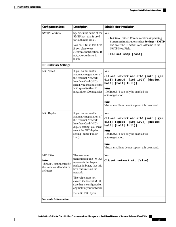
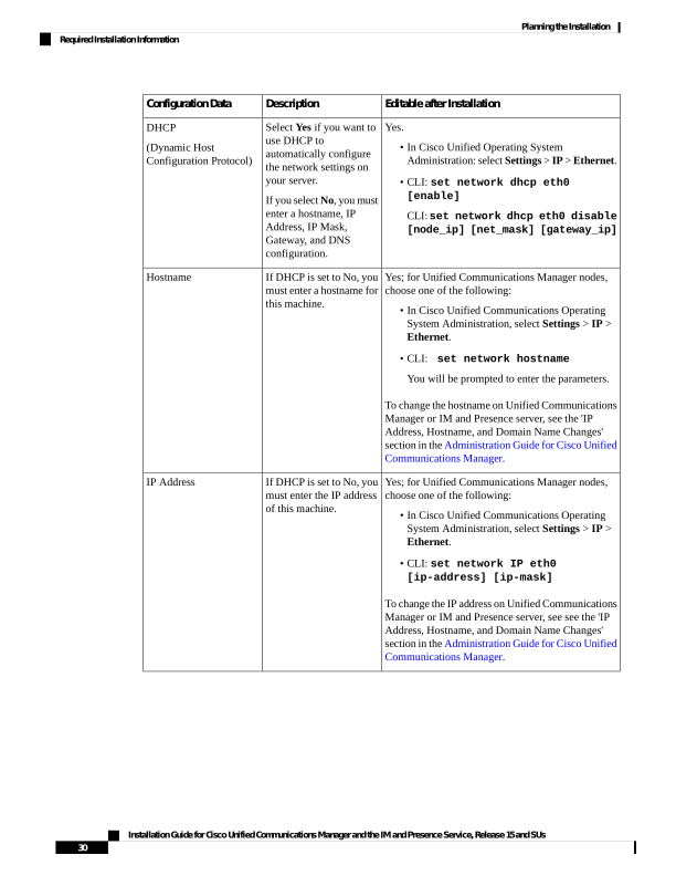
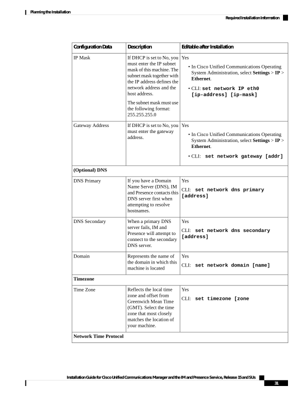
Required Installation Information
When you install either Unified Communications Manager or the IM and Presence Service on a server, the
installation process requires you to provide specific information. You can provide this information manually
during the installation process or you can provide it using an answer file. For each server that you install in
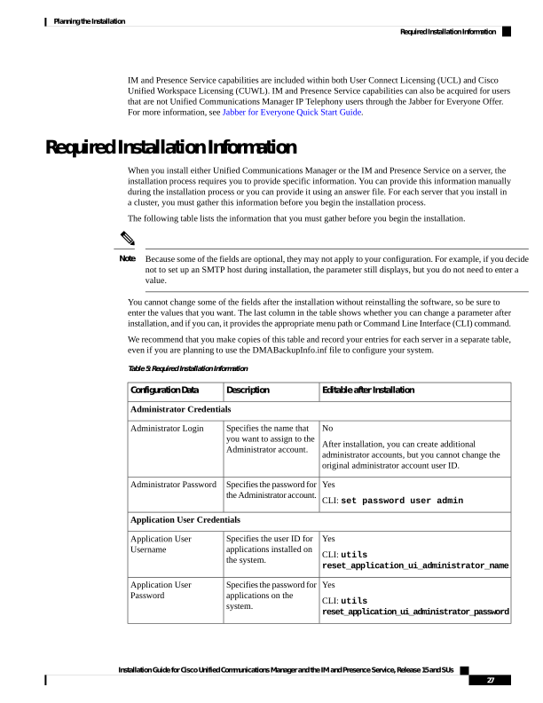
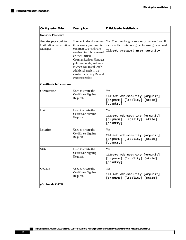
a cluster, you must gather this information before you begin the installation process.
The following table lists the information that you must gather before you begin the installation.
Because some of the fields are optional, they may not apply to your configuration. For example, if you decide
not to set up an SMTP host during installation, the parameter still displays, but you do not need to enter a
value.
Note
You cannot change some of the fields after the installation without reinstalling the software, so be sure to
enter the values that you want. The last column in the table shows whether you can change a parameter after
installation, and if you can, it provides the appropriate menu path or Command Line Interface (CLI) command.
We recommend that you make copies of this table and record your entries for each server in a separate table,
even if you are planning to use the DMABackupInfo.inf file to configure your system.
Table 5: Required Installation Information
Editable after Installation
Description
Configuration Data
Administrator Credentials
No
After installation, you can create additional
administrator accounts, but you cannot change the
original administrator account user ID.
Specifies the name that
you want to assign to the
Administrator account.
Administrator Login
Yes
CLI: set password user admin
Specifies the password for
the Administrator account.
Administrator Password
Application User Credentials
Yes
CLI: utils
reset_application_ui_administrator_name
Specifies the user ID for
applications installed on
the system.
Application User
Username
Yes
CLI: utils
reset_application_ui_administrator_password
Specifies the password for
applications on the
system.
Application User
Password
Installation Guide for Cisco Unified Communications Manager and the IM and Presence Service, Release 15 and SUs
27
Planning the Installation
Required Installation Information

Page 34
Editable after Installation
Description
Configuration Data
Security Password
Yes. You can change the security password on all
nodes in the cluster using the following command:
CLI: set password user security
Servers in the cluster use
the security password to
communicate with one
another. Set this password
on the Unified
CommunicationsManager
publisher node, and enter
it when you install each
additional node in the
cluster, including IM and
Presence nodes.
Security password for
Unified Communications
Manager
Certificate Information
Yes
CLI: set web-security [orgunit]
[orgname] [locality] [state]
[country]
Used to create the
Certificate Signing
Request.
Organization
Yes
CLI: set web-security [orgunit]
[orgname] [locality] [state]
[country]
Used to create the
Certificate Signing
Request.
Unit
Yes
CLI: set web-security [orgunit]
[orgname] [locality] [state]
[country]
Used to create the
Certificate Signing
Request.
Location
Yes
CLI: set web-security [orgunit]
[orgname] [locality] [state]
[country]
Used to create the
Certificate Signing
Request.
State
Yes
CLI: set web-security [orgunit]
[orgname] [locality] [state]
Used to create the
Certificate Signing
Request.
Country
(Optional) SMTP
Installation Guide for Cisco Unified Communications Manager and the IM and Presence Service, Release 15 and SUs
28
Planning the Installation
Required Installation Information
Page 35
Editable after Installation
Description
Configuration Data
Yes
• In Cisco Unified Communications Operating
System Administration: select Settings > SMTP
and enter the IP address or Hostname in the
SMTP Host Field.
• CLI: set smtp [host]
Specifies the name of the
SMTP host that is used
for outbound email.
You must fill in this field
if you plan to use
electronic notification. If
not, you can leave it
blank.
SMTP Location
NIC Interface Settings
Yes
CLI: set network nic eth0 {auto | {en|
dis}} {speed| {10| 100}} {duplex
half| {half| full}}
Note
1000BASE-T can only be enabled via
auto-negotiation.
Note
Virtual machines do not support this command.
If you do not enable
automatic negotiation of
the ethernet Network
Interface Card (NIC)
speed, you must select the
NIC speed (either 10
megabit or 100 megabit).
NIC Speed
Yes
CLI: set network nic eth0 {auto | {en|
dis}} {speed| {10| 100}} {duplex
half| {half| full}}
Note
1000BASE-T can only be enabled via
auto-negotiation.
Note
Virtual machines do not support this command.
If you do not enable
automatic negotiation of
the ethernet Network
Interface Card (NIC)
duplex setting, you must
select the NIC duplex
setting (either Full or
Half).
NIC Duplex
Yes
CLI: set network mtu [size]
The maximum
transmission unit (MTU)
represents the largest
packet, in bytes, that this
host transmits on the
network.
The value must not
exceed the lowest MTU
size that is configured on
any link in your network.
Default: 1500 bytes
MTU Size
Note
The MTU setting must be
the same on all nodes in
a cluster.
Network Information
Installation Guide for Cisco Unified Communications Manager and the IM and Presence Service, Release 15 and SUs
29
Planning the Installation
Required Installation Information
Page 36
Editable after Installation
Description
Configuration Data
Yes.
• In Cisco Unified Operating System
Administration: select Settings > IP > Ethernet.
• CLI: set network dhcp eth0
[enable]
CLI: set network dhcp eth0 disable
[node_ip] [net_mask] [gateway_ip]
Select Yes if you want to
use DHCP to
automatically configure
the network settings on
your server.
If you select No, you must
enter a hostname, IP
Address, IP Mask,
Gateway, and DNS
configuration.
DHCP
(Dynamic Host
Configuration Protocol)
Yes; for Unified Communications Manager nodes,
choose one of the following:
• In Cisco Unified Communications Operating
System Administration, select Settings > IP >
Ethernet.
• CLI:
set network hostname
You will be prompted to enter the parameters.
To change the hostname on Unified Communications
Manager or IM and Presence server, see the 'IP
Address, Hostname, and Domain Name Changes'
section in the Administration Guide for Cisco Unified
Communications Manager.
If DHCP is set to No, you
must enter a hostname for
this machine.
Hostname
Yes; for Unified Communications Manager nodes,
choose one of the following:
• In Cisco Unified Communications Operating
System Administration, select Settings > IP >
Ethernet.
• CLI: set network IP eth0
[ip-address] [ip-mask]
To change the IP address on Unified Communications
Manager or IM and Presence server, see see the 'IP
Address, Hostname, and Domain Name Changes'
section in the Administration Guide for Cisco Unified
Communications Manager.
If DHCP is set to No, you
must enter the IP address
of this machine.
IP Address
Installation Guide for Cisco Unified Communications Manager and the IM and Presence Service, Release 15 and SUs
30
Planning the Installation
Required Installation Information
Page 37
Editable after Installation
Description
Configuration Data
Yes
• In Cisco Unified Communications Operating
System Administration, select Settings > IP >
Ethernet.
• CLI: set network IP eth0
[ip-address] [ip-mask]
If DHCP is set to No, you
must enter the IP subnet
mask of this machine. The
subnet mask together with
the IP address defines the
network address and the
host address.
The subnet mask must use
the following format:
255.255.255.0
IP Mask
Yes
• In Cisco Unified Communications Operating
System Administration, select Settings > IP >
Ethernet.
• CLI:
set network gateway [addr]
If DHCP is set to No, you
must enter the gateway
address.
Gateway Address
(Optional) DNS
Yes
CLI:
set network dns primary
[address]
If you have a Domain
Name Server (DNS), IM
and Presence contacts this
DNS server first when
attempting to resolve
hostnames.
DNS Primary
Yes
CLI:
set network dns secondary
[address]
When a primary DNS
server fails, IM and
Presence will attempt to
connect to the secondary
DNS server.
DNS Secondary
Yes
CLI:
set network domain [name]
Represents the name of
the domain in which this
machine is located
Domain
Timezone
Yes
CLI:
set timezone [zone
Reflects the local time
zone and offset from
Greenwich Mean Time
(GMT). Select the time
zone that most closely
matches the location of
your machine.
Time Zone
Network Time Protocol
Installation Guide for Cisco Unified Communications Manager and the IM and Presence Service, Release 15 and SUs
31
Planning the Installation
Required Installation Information
Page 38
Editable after Installation
Description
Configuration Data
Yes
In Cisco Unified Communications Operating System
Administration, select Settings > NTP Servers.
During installation of the
IM and Presence
publisher node, you must
specify the IP address of
an external Network Time
Protocol (NTP) server.
We recommend that you
use the Unified
CommunicationsManager
publisher node as the NTP
server.
NTP Server IP Address
Export Restricted and Export Unrestricted Software
This release of Unified Communications Manager and IM and Presence Service supports an export unrestricted
(XU) version, in addition to the export restricted (K9) version.
Unrestricted versions of software are intended only for a specific set of customers who do not want various
security capabilities; unrestricted versions are not intended for general deployments.
Note
Export unrestricted versions differs from restricted versions as follows:
• Encryption of user payload (information exchange) is not supported.
• External SIP interdomain federation with Microsoft OCS/Lync or AOL is not supported.
• After you install an unrestricted release, you can never upgrade to a restricted version. A fresh install of
a restricted version on a system that contains an unrestricted version is also not supported.
• All nodes within a single cluster must be in the same mode. For example, Unified Communications
Manager and IM and Presence Service in the same cluster must either all be in unrestricted mode or all
be in restricted mode.
• IP Phone security configurations are modified to disable signaling and media encryption (including
encryption provided by the VPN phone feature).
Be aware that after you install an unrestricted release, you can never upgrade to a restricted version. You are
not allowed to perform a fresh installation of a restricted version on a system that contains an unrestricted
version.
Note
For all Graphical User Interfaces (GUIs) and Command Line Interfaces (CLIs), the Administrator can view
the product version (restricted or export unrestricted).
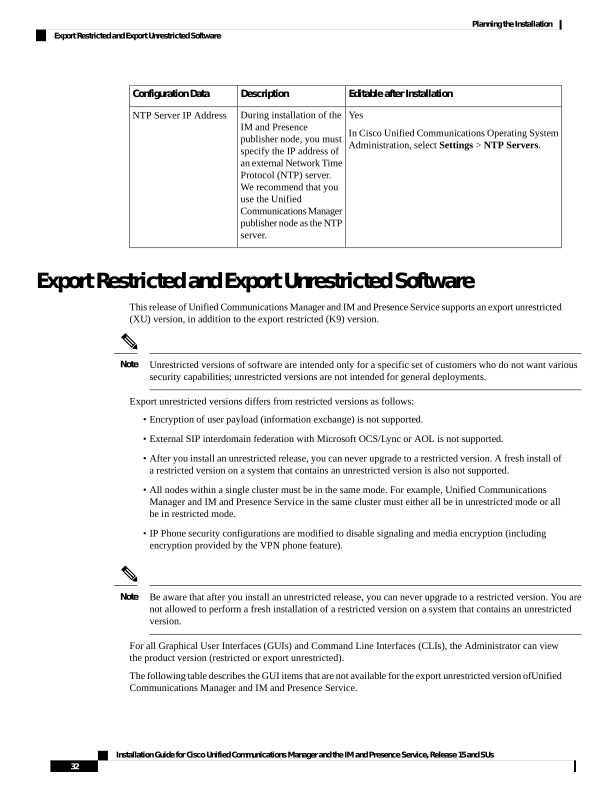
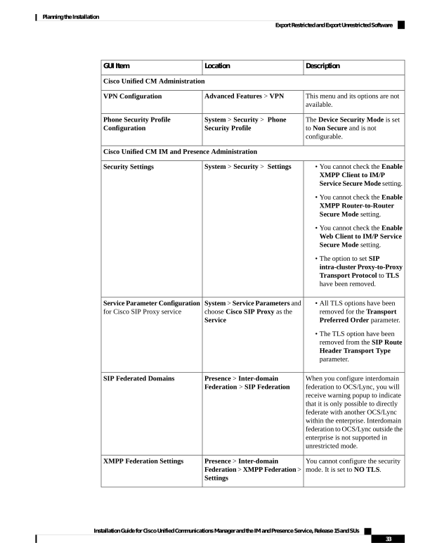
The following table describes the GUI items that are not available for the export unrestricted version ofUnified
Communications Manager and IM and Presence Service.
Installation Guide for Cisco Unified Communications Manager and the IM and Presence Service, Release 15 and SUs
32
Planning the Installation
Export Restricted and Export Unrestricted Software

Page 39
Description
Location
GUI Item
Cisco Unified CM Administration
This menu and its options are not
available.
Advanced Features > VPN
VPN Configuration
The Device Security Mode is set
to Non Secure and is not
configurable.
System > Security > Phone
Security Profile
Phone Security Profile
Configuration
Cisco Unified CM IM and Presence Administration
• You cannot check the Enable
XMPP Client to IM/P
Service Secure Mode setting.
• You cannot check the Enable
XMPP Router-to-Router
Secure Mode setting.
• You cannot check the Enable
Web Client to IM/P Service
Secure Mode setting.
• The option to set SIP
intra-cluster Proxy-to-Proxy
Transport Protocol to TLS
have been removed.
System > Security > Settings
Security Settings
• All TLS options have been
removed for the Transport
Preferred Order parameter.
• The TLS option have been
removed from the SIP Route
Header Transport Type
parameter.
System > Service Parameters and
choose Cisco SIP Proxy as the
Service
Service Parameter Configuration
for Cisco SIP Proxy service
When you configure interdomain
federation to OCS/Lync, you will
receive warning popup to indicate
that it is only possible to directly
federate with another OCS/Lync
within the enterprise. Interdomain
federation to OCS/Lync outside the
enterprise is not supported in
unrestricted mode.
Presence > Inter-domain
Federation > SIP Federation
SIP Federated Domains
You cannot configure the security
mode. It is set to NO TLS.
Presence > Inter-domain
Federation > XMPP Federation >
Settings
XMPP Federation Settings
Installation Guide for Cisco Unified Communications Manager and the IM and Presence Service, Release 15 and SUs
33
Planning the Installation
Export Restricted and Export Unrestricted Software
Page 40
Description
Location
GUI Item
You cannot set any TLS or HTTPS
listeners as the preferred proxy
listener.
Presence > Routing > Settings
Proxy Configuration Settings
Installation Guide for Cisco Unified Communications Manager and the IM and Presence Service, Release 15 and SUs
34
Planning the Installation
Export Restricted and Export Unrestricted Software

Page 41
C H A P T E R 3
Preinstallation Tasks
• Preinstall Tasks for Unified Communications Manager on VMware vSphere ESXi, on page 35
• Preinstall Tasks for Cisco Unified Communications Manager on Cisco NFVIS-for-UC, on page 37
• Preinstall Tasks for Cisco Unified Communications Manager on Nutanix AHV, on page 38
• Preinstall Tasks for IM and Presence Service on VMware vSphere ESXi, on page 39
• Preinstall Tasks for IM and Presence Service on Cisco NFVIS-for-UC, on page 40
• Preinstall Tasks for IM and Presence Service on Nutanix AHV, on page 41
Preinstall Tasks for Unified Communications Manager on
VMware vSphere ESXi
Procedure
Purpose
Command or Action
Review the Planning chapter. Make sure to
review the following:
Planning the Installation, on page 3
Step 1
• Decide on your Unified CM and IM and
Presence Service cluster Topology.
• Decide on the Hypervisor version that you
want and its supported hardware.
• Pick an installation method supported by
Hypervisor.
Review the installation requirements and record
the configuration settings for each server that
you plan to install.
Required Installation Information, on page 27
Step 2
Create virtual machines.
Step 3
• Get base OVA. An example OVA file
name is:
cucm_15_all_esxi_vmv17_or_nfvis_v1.0.sha512.ova.
Note
Installation Guide for Cisco Unified Communications Manager and the IM and Presence Service, Release 15 and SUs
35


Page 42
Purpose
Command or Action
From Release 15 onwards, the OVA
template is signed with sha512 using
Cisco authenticated certificates to ensure
that there is no tampering of the OVA file.
To avoid seeing the "The certificate is not
trusted" warning when using the OVA to
create a new Virtual Machine, use the
following steps:
a.
Navigate to https://www.cisco.com/
security/pki/codesign/.
b.
Download the Issuer Chain PKCS7
(PEM) file (right-click and choose
Save link as) for the selected
certificate that is used to sign the
OVA file. The signing certificate used
is documented in the File
Information of the downloaded OVA
page.
c.
Add these certificates to vCenter by
following the steps in the 'Resolution'
section at: https://kb.vmware.com/s/
article/84240.
For more information, refer to the technical
documentation on Broadcom.com.
Select a VM configuration from the Base OVA
and deploy using the OVA.
Step 4
Place the installation ISO file in a location
where the virtual machine can access it and edit
Mount the installation ISO file.
Step 5
the virtual machine's DVD drive to map to the
file. Select the option to mount the DVD drive
when you power on the virtual machine.
When you power on the virtual machine, it
mounts the ISO file and start the installation
process. Do not begin the installation process
until you have completed all the steps in this
procedure.
For more information, refer to the technical
documentation on Broadcom.com.
Installation Guide for Cisco Unified Communications Manager and the IM and Presence Service, Release 15 and SUs
36
Preinstallation Tasks
Preinstall Tasks for Unified Communications Manager on VMware vSphere ESXi
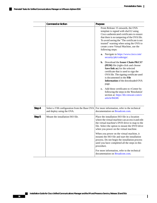
Page 43
Preinstall Tasks for Cisco Unified Communications Manager
on Cisco NFVIS-for-UC
Procedure
Purpose
Command or Action
Planning the Installation, on page 3
Step 1
• Decide on your Unified CM and IM and
Presence Service cluster Topology.
• Decide on the Hypervisor version that you
want and its supported hardware.
• Pick an installation method supported by
Hypervisor.
Review the installation requirements and record
the configuration settings for each server that
you plan to install.
Required Installation Information, on page 27
Step 2
An example OVA file name is:
cucm_15_all_esxi_vmv17_or_nfvis_v1.0.sha512.ova.
Upload the ISO image and OVA.
Step 3
Upload the OVA as a profile and the ISO as an
image together. This process creates a separate
profile for each VM configuration and a single
image for the bootable ISO. For more
information, refer to the 'Image Registration for
CUCM Applications' section in the Cisco
Enterprise Network Function Virtualization
Infrastructure Software Configuration Guide.
Deploy a VM.
Step 4
a.
Ensure that an OVA and ISO image is
already uploaded.
b.
Navigate to Configuration > Deploy.
c.
Select OTHER as the option when creating
virtual machines for your application type.
d. Connect to the virtual network and assign
the Image/Profile (depending on the
deployment size that you prefer), and click
Deploy.
e.
Open the VM console via Configuration
Virtual Machine > Manage.
f.
Use the console to complete the ISO
installation process.
Installation Guide for Cisco Unified Communications Manager and the IM and Presence Service, Release 15 and SUs
37
Preinstallation Tasks
Preinstall Tasks for Cisco Unified Communications Manager on Cisco NFVIS-for-UC
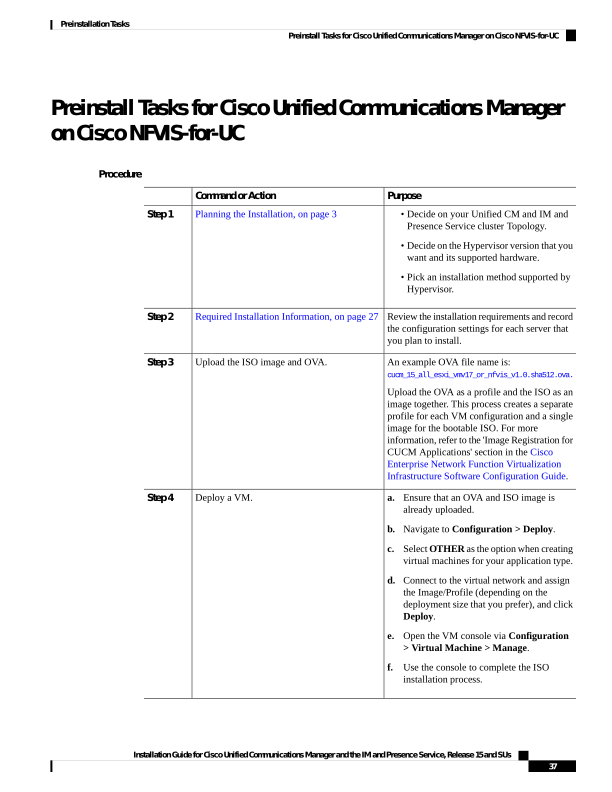
Page 44
Preinstall Tasks for Cisco Unified Communications Manager
on Nutanix AHV
Procedure
Purpose
Command or Action
Plan the installation
Step 1
• Decide on the Unified CM and IM and
Presence Service cluster Topology.
• Decide on the Hypervisor version that you
want and its supported hardware and
hyperconvergence software version.
• Pick an installation method supported by
Hypervisor.
Review the installation requirements and record
the configuration settings for each server that
you plan to install.
Required Installation Information, on page 27
Step 2
An example OVA file name for a large size
deployment is:
cucm_15_large_ahv_v1.0.sha512.ova.
Create virtual machines in Nutanix AHV and
select an OVA per each VM configuration from
the Base OVA and deploy using the OVA.
Step 3
a.
Download the Unified CM .ova files based
on the required configuration from the
Software Download page .
b.
Upload the Unified CM .ova files
(downloaded) onto the Nutanix cluster
using Prism Central.
c.
Download the desired Unified CM bootable
.iso image version from the Software
Download page and upload the image to
the Nutanix cluster.
d. Creating Unified CM Publisher and
Subscriber VMs using the .ova files.
e.
Update Unified CM VMs to mount
CD-ROM with the Unified CM image.
Installation Guide for Cisco Unified Communications Manager and the IM and Presence Service, Release 15 and SUs
38
Preinstallation Tasks
Preinstall Tasks for Cisco Unified Communications Manager on Nutanix AHV
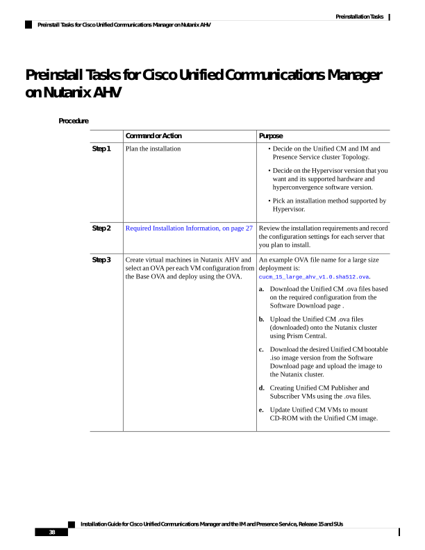
Page 45
Preinstall Tasks for IM and Presence Service on VMware
vSphere ESXi
Procedure
Purpose
Command or Action
Review the Planning chapter. Make sure to
review the following:
Planning the Installation, on page 3
Step 1
• Decide on your IM and Presence Service
and Unified CM cluster Topology.
• Decide on the Hypervisor that you want
and its supported hardware.
• Pick an installation method supported by
Hypervisor.
Make sure that the Unified Communications
Manager and IM and Presence Service software
versions are compatible.
Supported Version
Step 2
Gather all the information you need to complete
the installation and configuration of the IM and
Presence Service.
Required Installation Information, on page 27
Step 3
For every node in your cluster, create virtual
machines using the Virtual Server Template
Create your virtual machines.
Step 4
(OVA file) that is recommended for your
release. An example OVA file name is:
imp_15_all_esxi_vmv17_or_nfvis_v1.0.sha512.ova.
Note
From Release 15 onwards, the OVA template
is signed with sha512 using Cisco authenticated
certificates to ensure that there is no tampering
of the OVA file. To avoid seeing the "The
certificate is not trusted" warning when using
the OVA to create a new Virtual Machine, use
the following steps:
a.
Navigate to https://www.cisco.com/
security/pki/codesign/.
b.
Download the Issuer Chain PKCS7
(PEM) file (right-click and choose Save
link as) for the selected certificate that is
used to sign the OVA file. The signing
certificate used is documented in the File
Installation Guide for Cisco Unified Communications Manager and the IM and Presence Service, Release 15 and SUs
39
Preinstallation Tasks
Preinstall Tasks for IM and Presence Service on VMware vSphere ESXi
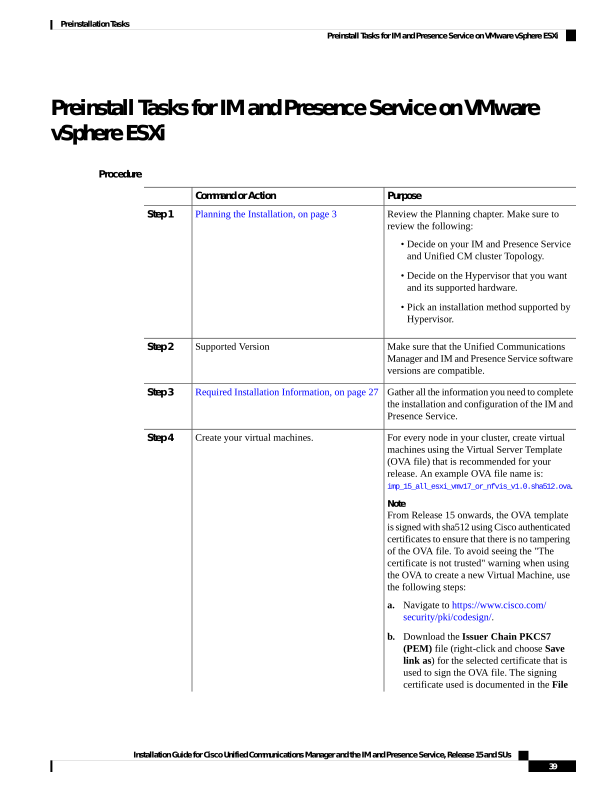
Page 46
Purpose
Command or Action
Information of the downloaded OVA
page.
c.
Add these certificates to vCenter by
following the steps in the 'Resolution'
section at: https://kb.vmware.com/s/article/
84240.
Different OVA files are available; choose the
correct OVA file based on the environment in
which you are deploying Unified
Communications Manager. See Virtualization
Requirements, on page 14.
Make sure that each IM and Presence Service
server has network access to the Unified
Verify network connectivity.
Step 5
Communications Manager publisher server.
Ping the Unified Communications Manager
publisher node from the other IM and Presence
Service servers.
Preinstall Tasks for IM and Presence Service on Cisco
NFVIS-for-UC
Procedure
Purpose
Command or Action
Planning the Installation, on page 3
Step 1
• Decide on your IM and Presence Service
and Unified CM cluster Topology.
• Decide on the Hypervisor version that you
want and its supported hardware.
• Pick an installation method supported by
Hypervisor.
Review the installation requirements and record
the configuration settings for each server that
you plan to install.
Required Installation Information, on page 27
Step 2
Upload the OVA (an example OVA file name
is:
Upload the OVA and ISO image.
Step 3
imp_15_all_esxi_vmv17_or_nfvis_v1.0.sha512.ova)
as a profile and the ISO as an image together.
This process creates a separate profile for each
VM configuration and a single image for the
Installation Guide for Cisco Unified Communications Manager and the IM and Presence Service, Release 15 and SUs
40
Preinstallation Tasks
Preinstall Tasks for IM and Presence Service on Cisco NFVIS-for-UC
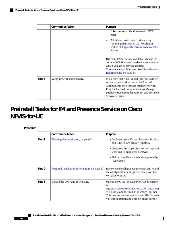
Page 47
Purpose
Command or Action
bootable ISO. For more information, refer to
the Cisco Enterprise Network Function
Virtualization Infrastructure Software
Configuration Guide.
Deploy a VM.
Step 4
a.
Ensure that an OVA and ISO image is
already uploaded.
b.
Navigate to Configuration > Deploy.
c.
Select OTHER as the option when creating
virtual machines for your application type.
d. Connect to the virtual network and assign
the Image/Profile (depending on the
deployment size that you prefer), and click
Deploy.
e.
Open the VM console via Configuration
Virtual Machine > Manage.
f.
Use the console to complete the ISO
installation process.
Preinstall Tasks for IM and Presence Service on Nutanix AHV
Procedure
Purpose
Command or Action
Plan the installation
Step 1
• Decide on the IM and Presence Service
and Unified CM cluster Topology.
• Decide on the Hypervisor version that you
want and its supported hardware and
hyperconvergence software version.
• Pick an installation method supported by
Hypervisor.
Review the installation requirements and record
the configuration settings for each server that
you plan to install.
Required Installation Information, on page 27
Step 2
An example OVA file name for a medium sized
deployment is:
imp_15_medium_ahv_v1.0.sha512.ova.
Create virtual machines in Nutanix AHV and
select an OVA per each VM configuration from
the Base OVA and deploy using the OVA.
Step 3
Installation Guide for Cisco Unified Communications Manager and the IM and Presence Service, Release 15 and SUs
41
Preinstallation Tasks
Preinstall Tasks for IM and Presence Service on Nutanix AHV
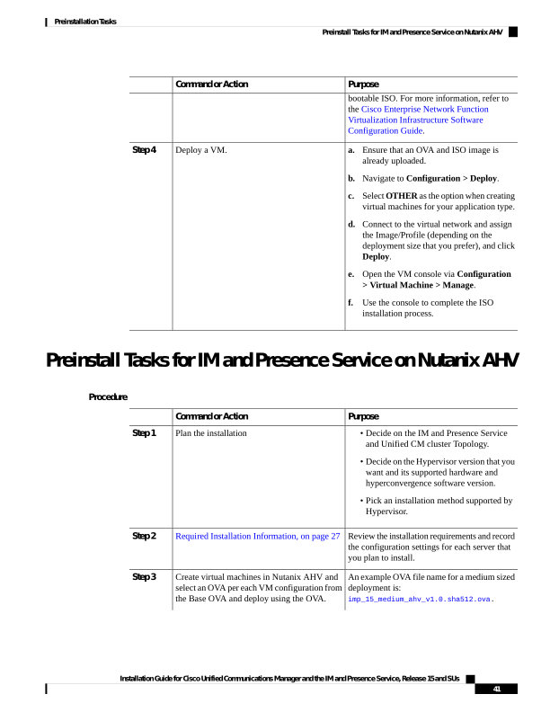
Page 48
Purpose
Command or Action
a.
Download the IMP.ova files based on the
required configuration from the Software
Download page.
b.
Upload the IMP.ova files (downloaded)
onto the Nutanix cluster using Prism
Central.
c.
Download the desired IMP bootable .iso
image version from the Software Download
page and upload the image to the Nutanix
cluster.
d. Creating IM and Presence Service Publisher
and Subscriber VMs using the .ova files.
e.
UpdateIM and Presence Service VMs to
mount CD-ROM with the IM and Presence
Service image.
Installation Guide for Cisco Unified Communications Manager and the IM and Presence Service, Release 15 and SUs
42
Preinstallation Tasks
Preinstall Tasks for IM and Presence Service on Nutanix AHV

Page 49
C H A P T E R 4
Installation Methods
• Installation Methods Task Flows For VMware vSphere ESXi, on page 43
• Installation Methods Task Flows For Cisco NFVIS-for-UC, on page 45
• Installation Methods Task Flows For Nutanix AHV, on page 45
• Attended Installation Task Flow, on page 46
• Touchless Installation Task Flow for ESXi, on page 60
• Touchless Installation Task Flow For Cisco NFVIS-for-UC, on page 64
• Touchless Installation Task Flow for Nutanix AHV, on page 69
• Automated Installation using vApp properties and VMware OVF Tool, on page 72
• Install with Data Import, on page 75
• Add a New Node to an Existing Cluster, on page 79
Installation Methods Task Flows For VMware vSphere ESXi
Choose one of the following installation methods task flows:
Description
Task Flow
Use this method for basic installs of any of the following deployments:
• Unified Communications Manager telephony cluster installs
• Standard Deployments (Decentralized) for IM and Presence
Attended Installation Task Flow,
on page 46
Use this task flow to install a Unified Communications Manager or IM
and Presence Service cluster dynamically without the need for manual
intervention. Applies to either Centralized or Standard (Decentralized)
IM and Presence deployments.
Touchless Installation Task Flow
for ESXi, on page 60
(Applicable only to VMware vSphere ESXi) Use this method to install
a Unified Communications Manager or IM and Presence Service cluster
using skip-install OVAs.
Automated Installation using vApp
properties and VMware OVF Tool,
on page 72
Complete this task to install a Unified Communications Manager or IM
and Presence Service cluster using the Install with Data Import.
Install with Data Import, on page
75
Complete these tasks if you want to add a node to an existing Unified
Communications Manager or IM and Presence Service cluster.
Add a New Node to an Existing
Cluster, on page 79
Installation Guide for Cisco Unified Communications Manager and the IM and Presence Service, Release 15 and SUs
43

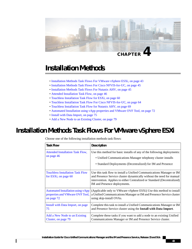
Page 50
Installation Wizard Considerations
Before you begin the installation, review the following information:
• Make sure that the subscriber nodes that you are installing can connect to the publisher node
server during the installation.
• Make sure that all Unified Communications Manager servers in a cluster have the same software
version. Make sure that all IM and Presence Service servers in a cluster have the same version
of the released software. The only exception is during a cluster software upgrade, during which
a temporary mismatch is allowed. If you are installing IM and Presence Service nodes, Unified
Communications Manager and IM and Presence Service software versions must have the same
major and minor release number.
• If you are installing on an existing cluster, do not attempt to perform any configuration tasks
during the installation.
• Note that directory names and filenames that you enter while you are running the installation
program are case-sensitive.
• For IM and Presence Service installations, make sure that you know whether you are installing
IM and Presence Service in a Centralized Cluster Deployment or in a Standard Deployment
(de-centralized/distributed).
Installation Wizard
The following table provides instructions on how to navigate within the installation wizard.
Table 6: Installation Wizard Navigation
Press This
To Do This
Tab
Move to the next field
Alt-Tab
Move to the previous field
Space bar or Enter
Choose an option
Up or down arrow
Scroll up or down in a list
Space bar or Enter to choose Back (when available)
Go to the previous window
Space bar or Enter to choose Help (when available)
Get help information on a window
Installation Guide for Cisco Unified Communications Manager and the IM and Presence Service, Release 15 and SUs
44
Installation Methods
Installation Wizard Considerations
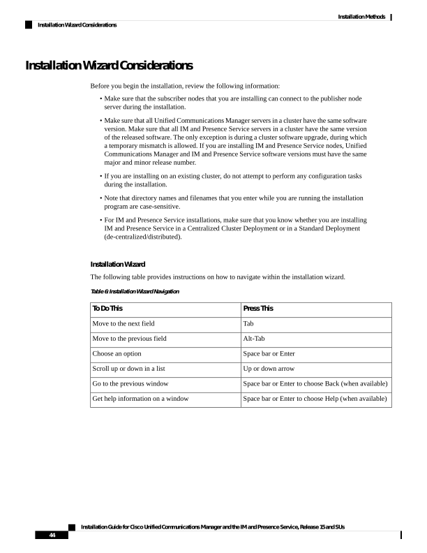
Page 51
The installation wizard supports the following characters:
• alphanumeric: A-Z, a-z, and 0-9- spaces
• spaces and # (except as the first character)
• only the following special characters: .,-_:;{}()[]
All other characters are not supported.
Note
Installation Methods Task Flows For Cisco NFVIS-for-UC
Choose one of the following installation methods task flows:
Description
Task Flow
Use this method for basic installs of any of the following deployments:
• Unified Communications Manager telephony cluster installs
• Standard Deployments (Decentralized) for IM and Presence
Attended Installation Task Flow,
on page 46
Use this task flow to install a Unified Communications Manager or IM
and Presence Service cluster dynamically without the need for manual
intervention. Applies to either Centralized or Standard (Decentralized)
IM and Presence deployments.
Touchless Installation Task Flow
For Cisco NFVIS-for-UC, on page
64
Complete this task to install a Unified Communications Manager or IM
and Presence Service cluster using the Install with Data Import.
Install with Data Import, on page
75
Complete these tasks if you want to add a node to an existing Unified
Communications Manager or IM and Presence Service cluster.
Add a New Node to an Existing
Cluster, on page 79
Installation Methods Task Flows For Nutanix AHV
Choose one of the following installation methods task flows:
Description
Task Flow
Use this method for basic installs of any of the following deployments:
• Unified Communications Manager telephony cluster installs
• Standard Deployments (Decentralized) for IM and Presence
Attended Installation Task Flow,
on page 46
Use this task flow to install a Unified Communications Manager or IM
and Presence Service cluster dynamically without the need for manual
intervention. Applies to either Centralized or Standard (Decentralized)
IM and Presence deployments.
Touchless Installation Task Flow
for Nutanix AHV, on page 69
Installation Guide for Cisco Unified Communications Manager and the IM and Presence Service, Release 15 and SUs
45
Installation Methods
Installation Methods Task Flows For Cisco NFVIS-for-UC

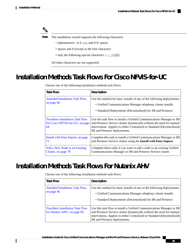
Page 52
Description
Task Flow
Complete this task to install a Unified Communications Manager or IM
and Presence Service cluster using the Install with Data Import.
Install with Data Import, on page
75
Complete these tasks if you want to add a node to an existing Unified
Communications Manager or IM and Presence Service cluster.
Add a New Node to an Existing
Cluster, on page 79
Attended Installation Task Flow
Complete the following tasks to install Unified Communications Manager and IM and Presence Service cluster
using the basic attended installation process:
• Installs of a Unified Communications Manager telephony cluster
• Installs of the IM and Presence Service in a Standard Deployment (de-centralized/distributed).
Depending on your installation scenario, you may not need to perform all the tasks. For example, if you are
installing the IM and Presence Service on an existing Unified Communications Manager cluster that is already
in use, you only need to complete the tasks for installing the IM and Presence Service.
Note
Before You Begin
Preinstall Tasks for Unified Communications Manager on VMware vSphere ESXi, on page 35
Preinstall Tasks for Cisco Unified Communications Manager on Cisco NFVIS-for-UC, on page 37
Preinstall Tasks for Cisco Unified Communications Manager on Nutanix AHV, on page 38
Preinstall Tasks for IM and Presence Service on VMware vSphere ESXi, on page 39
Description
IM and Presence Service
Unified Communications
Manager
Begin the install process for
Unified Communications
Manager.
—
Attended Installation, on page
48
Step 1
Upgrade your install image to
a newer version. This optional
task is available for Unified
Communications Manager
installs only.
—
(Optional) Complete either of
the following tasks:
• Upgrade Install Image
from Local Source, on
page 50
• Upgrade Install Image
from Remote Server, on
page 51
Step 3
Installation Guide for Cisco Unified Communications Manager and the IM and Presence Service, Release 15 and SUs
46
Installation Methods
Attended Installation Task Flow

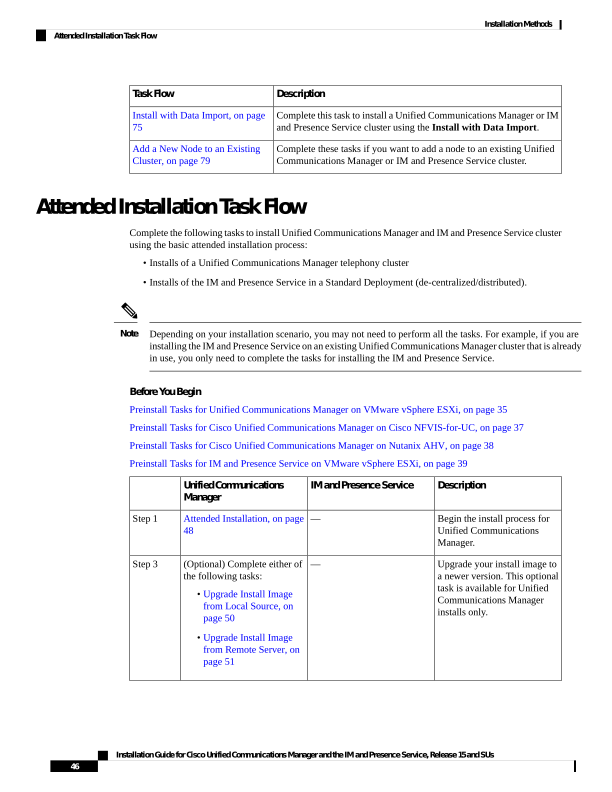
Page 53
Description
IM and Presence Service
Unified Communications
Manager
Continue with the Attended
Installation process by
configuring your installation.
—
Configure Attended
Installation, on page 53
Step 4
Configure and install software
on the publisher node.
—
Configure the Unified
Communications Manager
Publisher, on page 55
Step 5
Add subscriber nodes to the
publisher node.
—
Add Subscriber Nodes, on
page 58
Step 6
Install software on your
Unified Communications
Manager subscriber nodes.
—
Install Subscriber Nodes, on
page 59
Step 7
Begin the install process for the
IM and Presence Service.
Attended Installation, on page
48
—
Step 8
Continue Attended Install
process for IM and Presence
Service by configuring the
installation.
Configure Attended
Installation, on page 53
—
Step 10
Configure and complete the
installation for the IM and
Presence Service database
publisher node.
Configure the IM and Presence
Publisher, on page 58
—
Step 11
On the Unified
Communications Manager
publisher node, add the IM and
Presence Service subscribers.
—
Add Subscriber Nodes, on
page 58
Step 12
Install software on your IM and
Presence Service subscriber
nodes.
Install Subscriber Nodes, on
page 59
—
Step 13
Install IM and Presence Central Cluster (Attended Installation)
Complete these tasks to install an IM and Presence Service Centralized Deployment using basic attended
Installation.
• Unified CM Publisher (non-telephony)—The IM and Presence central cluster requires a local Unified
Communications Manager publisher node within the central cluster for database and user provisioning.
This node does not handle telephony. There is no need to install subscriber nodes.
• IM and Presence Service Central Cluster
Installation Guide for Cisco Unified Communications Manager and the IM and Presence Service, Release 15 and SUs
47
Installation Methods
Install IM and Presence Central Cluster (Attended Installation)
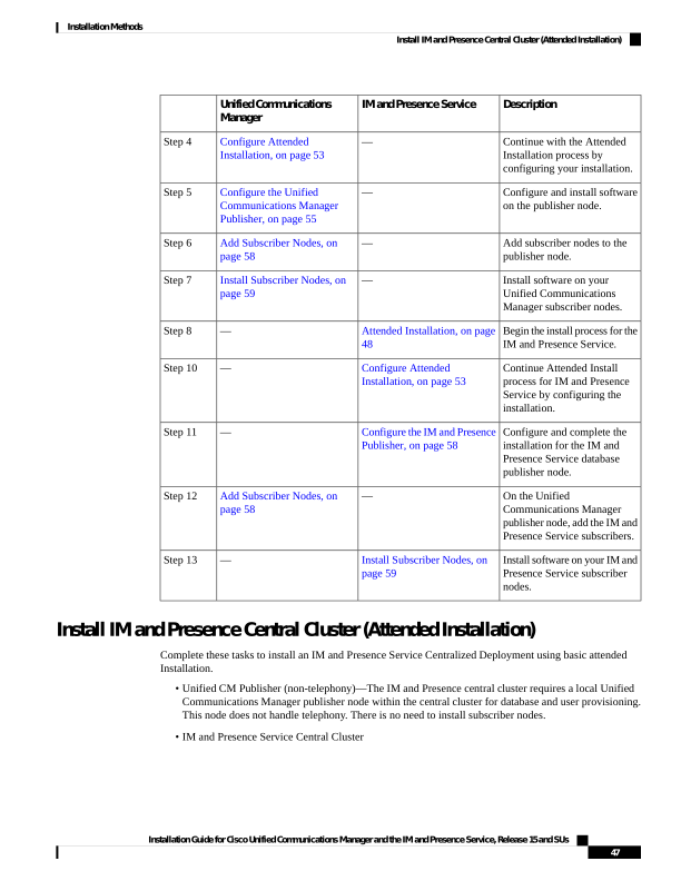
Page 54
For basic installation of IM and Presence Service in a de-centralized/distributed (Standard) deployment, follow
the Installation Methods Task Flows For VMware vSphere ESXi, on page 43 to install both the telephony
and IM and Presence Service clusters.
Note
Description
IM and Presence Service
Central Cluster
Unified CM Publisher
(non-telephony)
Begin the install process for the
Unified CM publisher node.
—
Attended Installation, on page
48
Step 1
Configure the Basic
Installation.
—
Configure Attended
Installation, on page 53
Step 2
Configure the Unified CM
publisher node.
—
Configure the Unified
Communications Manager
Publisher, on page 55
Step 3
Begin the install process for the
IM and Presence central cluster.
Attended Installation, on page
48
—
Step 4
Continue with the Basic Install
process for IM and Presence
Service by continuing the
installation.
Configure Attended
Installation, on page 53
—
Step 5
Configure the IM and Presence
Service database publisher
node.
Configure the IM and Presence
Publisher, on page 58
—
Step 6
On the Unified CM publisher,
add IM and Presence Service
subscriber nodes.
—
Add Subscriber Nodes, on page
58
Step 7
Complete the installation on the
IM and Presence Service
subscribers.
Install Subscriber Nodes, on
page 59
—
Step 8
Attended Installation
Use this procedure for Unified Communications Manager and IM and Presence Service installations to begin
the basic install process. You can use this procedure if you are installing a cluster or adding a node to an
existing cluster.
Procedure
Step 1
Perform one of the following:
• If you are installing from a DVD drive located on a VMware ESXi server host, insert the installation
DVD into the tray and restart the virtual machine, so that it boots from the DVD.
Installation Guide for Cisco Unified Communications Manager and the IM and Presence Service, Release 15 and SUs
48
Installation Methods
Attended Installation

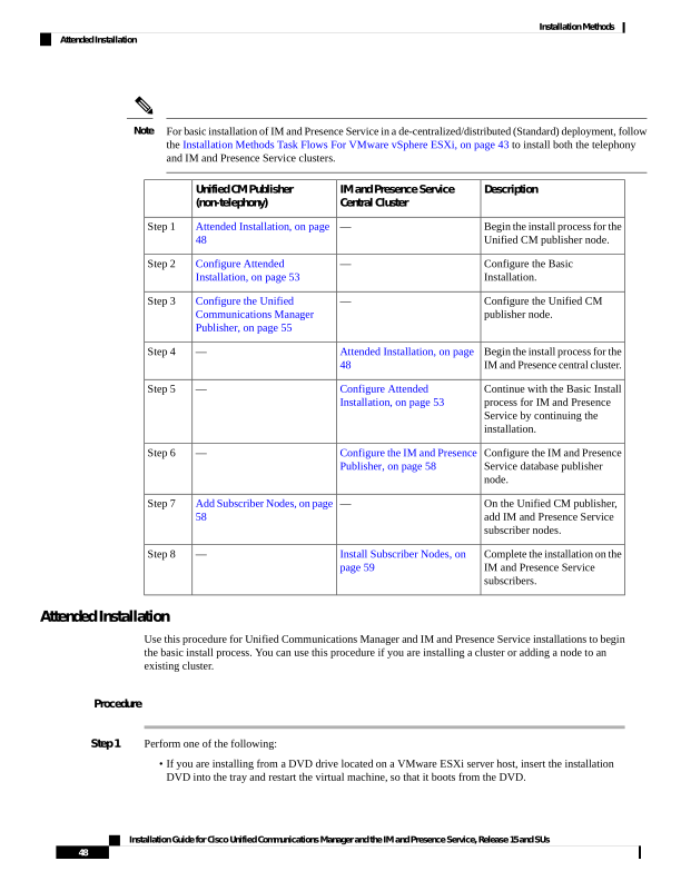
Page 55
• If you are installing from a data store ISO file located on the local ESXi host or on a storage area network
(SAN), edit the CD or DVD drive on the virtual machine to select the data store ISO file. Select the
option to connect at power on, and restart the virtual machine. If you have configured the virtual machine
to use the ISO at the same time that you created the virtual machine using the OVA file, skip this step
and complete the rest of the procedure.
Note
If you are installing Unified CM or IM and Presence Service from a Cisco Business Edition 6000/7000
appliance with the software pre-installed, go directly to the Installation Guide for Cisco Business Edition
6000 and 7000 for more information.
After the server completes the boot sequence, the DVD Found window displays.
Step 2
Click Yes to perform the media check. Or click No to skip the media check.
The media check verifies the integrity of the DVD or ISO. If the DVD or ISO has passed the media check
previously, choose to skip the media check.
Step 3
If you click Yes to perform the media check, the Media Check Result window displays.
a)
If the Media Check Result displays Pass, click OK to continue the installation.
b) If the media check fails, either download another copy from cisco.com or obtain another DVD or ISO
directly from Cisco.
Step 4
In the Product Deployment Selection window, specify which product you want to install:
• Unified Communications Manager—Choose the product and click OK.
• IM and Presence Service—Select OK.
Note
The window displays the products that are supported and not supported by your hardware. If only one product
is supported, you do not choose which product to install.
Step 5
If the Unified CM or IM and Presence Service software is pre-installed on the server, the Overwrite Hard
Drive window opens and displays the current software version on your hard drive, DVD or ISO file. Click
Yes to continue with the installation or No to cancel.
Caution
If you choose to continue with the installation, all existing data on your hard drive gets overwritten and
destroyed.
The Platform Installation Wizard window displays.
Step 6
In the Platform Installation Wizard window, choose one of the following options:
• To continue with the basic installation process, choose Proceed and continue. Allows you to configure
the basic installation process. Use this installation method first-time setup or during restore from backup.
• To continue with Install with Data Import, choose Import. Use this installation method for direct
migrations (Fresh Install with Data Import) from the older versions of Unified Communications Manager
or IM and Presence Service.
• If you want to install the software first and then configure it later, click Skip. The installation process
installs the software and then prompts you to configure it after the installation is complete. This method
may increase the total time for the installation.
Step 7
In the Apply Additional Release window, if you have a newer Unified Communications Manager SU version
on the same major release than your install image, you can elect to upgrade the installation to the newer release.
This option is not available for the IM and Presence Service.
Installation Guide for Cisco Unified Communications Manager and the IM and Presence Service, Release 15 and SUs
49
Installation Methods
Attended Installation

Page 56
• Yes—Choose this option to upgrade the Unified Communications Manager install image to a newer
Service Release. Go to one of the following procedures:
• Upgrade Install Image from Local Source, on page 50
• Upgrade Install Image from Remote Server, on page 51
• No—Choose this option if you are installing the IM and Presence Service or if you are installing Unified
Communications Manager and you do not want to upgrade the installed image.
Step 8
In the Basic Install window, click Continue to install the software or configure the pre-installed software.
What to do next
To upgrade the Unified Communications Manager install image to a later release, perform any of the following
procedures:
• Upgrade Install Image from Local Source, on page 50
• Upgrade Install Image from Remote Server, on page 51
To continue the basic install process, Configure Attended Installation, on page 53.
Upgrade Install Image from Local Source
Use this optional procedure for Unified Communications Manager installations if you have a newer version
than your installation image and you want to upgrade your installation file to a newer version. This option is
available for Unified Communications Manager installs only.
If you have placed your upgrade file on an FTP or SFTP server, see Upgrade Install Image from Remote
Server, on page 51.
Note
Before you begin
Make sure to do the following:
To complete this procedure, you must have completed the Attended Installation, on page 48 procedure and
have chosen to apply a patch via a LOCAL source.
Note
• Start a basic installation. Choose the option to apply a patch via a LOCAL source. For details, see Attended
Installation, on page 48.
• Download the appropriate patch file from Cisco.com. You must create an ISO image from the upgrade
file and then either place it on a DVD or in the DVD drive of a virtual machine.
Installation Guide for Cisco Unified Communications Manager and the IM and Presence Service, Release 15 and SUs
50
Installation Methods
Upgrade Install Image from Local Source

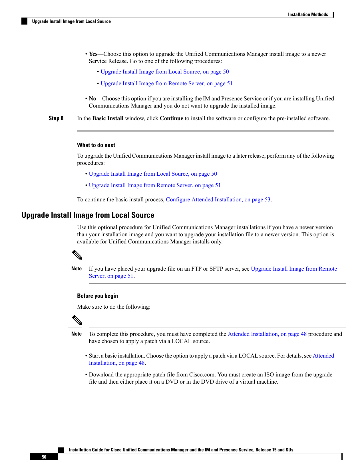
Page 57
Procedure
Step 1
When the Local Patch Configuration window displays, enter the patch directory and patch name, if required,
and choose OK.
The Install Upgrade Patch Selection Validation window displays.
Step 2
The window displays the patch file. To update the system with this patch, click Continue.
Step 3
Choose the upgrade patch to install. The system installs the patch, then restarts the system with the upgraded
software version running.
After the system restarts, the Preexisting Configuration Information window displays.
Step 4
To continue the installation, choose Proceed .
The Platform Installation Wizard window displays.
Step 5
To continue the installation, click Proceed or click Cancel to stop the installation.
If you click Proceed, the Apply Patch window displays. Continue with the next step.
If you click Cancel, the system halts, and you can safely power down the server.
Step 6
When the Apply Patch window displays, choose No.
Step 7
The Upgrade window displays.
Step 8
Click No and perform the procedure to configure the basic installation.
What to do next
Configure Attended Installation, on page 53
Upgrade Install Image from Remote Server
Use this optional procedure for Unified Communications Manager installations if you have a newer version
than your installation image on an FTP or SFTP server and you want to upgrade your installation file to a
newer version. This option is available for Unified Communications Manager installs only.
If you have placed your upgrade file on an FTP or SFTP server, see Upgrade Install Image from Local Source,
on page 50.
Note
Procedure
Step 1
Configure the auto negotiation setting.
• To enable automatic negotiation, choose Yes. This option sets the speed and duplex settings of the
Ethernet network interface card (NIC) by using automatic negotiation. The MTU Configuration window
displays. Skip the next step and then continue.
Installation Guide for Cisco Unified Communications Manager and the IM and Presence Service, Release 15 and SUs
51
Installation Methods
Upgrade Install Image from Remote Server

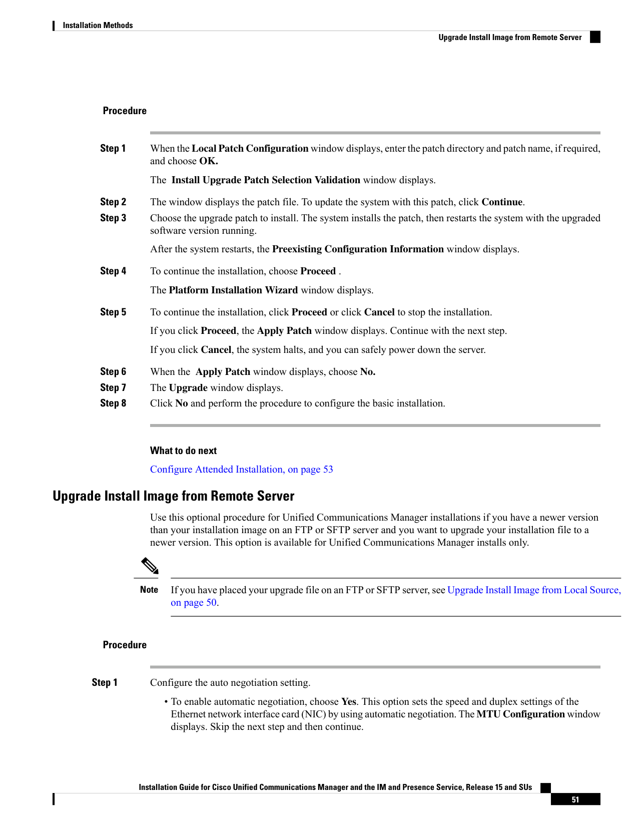
Page 58
Note
To use this option, your hub or the Ethernet switch must support automatic negotiation.
• To disable automatic negotiation, choose No. The NIC Speed and Duplex Configuration window displays.
Continue with the next step.
Step 2
If you chose to disable automatic negotiation, manually choose the appropriate NIC speed and duplex settings
now and choose OK to continue.
The MTU Configuration window displays.
Step 3
In the MTU Configuration window, you can change the MTU size from the operating system default.
The maximum transmission unit (MTU) represents the largest packet, in bytes, that this host transmits on the
network. If you are unsure of the MTU setting for your network, use the default value.
Caution
If you configure the MTU size incorrectly, your network performance can be affected.
• To accept the default value (1500 bytes), choose No.
• To change the MTU size from the operating system default, choose Yes, enter the new MTU size, and
choose OK.
The DHCP Configuration window displays.
Step 4
For network configuration, you can choose to either set up static network IP addresses for the node and gateway
or to use Dynamic Host Configuration Protocol (DHCP). Static IP addresses are recommended. If you use
DHCP, use static DHCP.
• If you have a DHCP server that is configured in your network and want to use DHCP, choose Yes. The
installation process attempts to verify network connectivity.
• If you want to configure static IP addresses for the node, choose No. The Static Network Configuration
window displays.
Step 5
If you chose not to use DHCP, enter your static network configuration values and choose OK.
The DNS Client Configuration window displays.
Step 6
To enable DNS, choose Yes, enter your DNS client information, and choose OK.
After the system configures the network and checks for connectivity, the Remote Patch Configuration window
displays.
Step 7
Enter the location and login information for the remote file server. The system connects to the remote server
and retrieves a list of available upgrade patches.
If the upgrade file is located on a Linux or Unix server, you must enter a forward slash at the beginning of
the directory path. For example, if the upgrade file is in the patches directory, you must enter /patches.
If the upgrade file is located on a Windows server, remember that you are connecting to an FTP or SFTP
server, so use the appropriate syntax, including:
• Begin the path with a forward slash (/) and use forward slashes throughout the path.
• The path must start from the FTP or SFTP root directory on the server, so you cannot enter a Windows
absolute path, which starts with a drive letter (for example, C:).
Installation Guide for Cisco Unified Communications Manager and the IM and Presence Service, Release 15 and SUs
52
Installation Methods
Upgrade Install Image from Remote Server
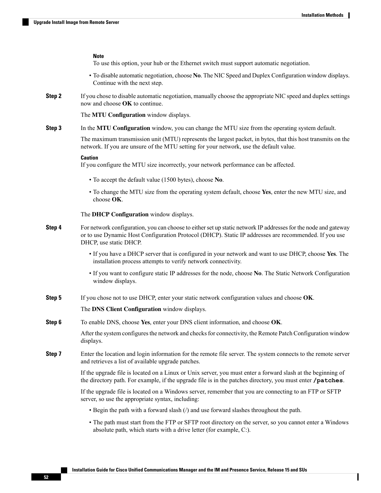
Page 59
The Install Upgrade Patch Selection window displays.
Step 8
Choose the upgrade patch to install. The system downloads, unpacks, and installs the patch and then restarts
the system with the upgraded software version running.
After the system restarts, the Preexisting Configuration Information window displays.
Step 9
To continue the installation, choose Proceed.
The Platform Installation Wizard window displays.
Step 10
Choose Proceed or choose Cancel to stop the installation.
If you choose Proceed, the Apply Patch window displays. Continue with the next step.
If you choose Cancel, the system halts, and you can safely power down the server.
Step 11
In the Apply Patch window displays, choose No.
The Windows Upgrade window displays.
Step 12
Choose No and perform the Configure Attended Installation, on page 53 procedure to configure the basic
installation.
What to do next
Configure Attended Installation, on page 53
Configure Attended Installation
Use this procedure to configure Unified Communications Manager and IM and Presence Service basic
installation.
Before you begin
Attended Installation, on page 48
Procedure
Step 1
In the Timezone Configuration window, choose the appropriate time zone for the server and then choose
OK.
The Auto Negotiation Configuration window is displayed.
Step 2
The installation process allows you to automatically set the speed and duplex settings of the Ethernet network
interface card (NIC) by using automatic negotiation. You can change this setting after installation.
• To enable automatic negotiation, choose Yes.
The MTU Configuration window is displayed.
Note
To use this option, your hub or Ethernet switch must support automatic negotiation.
Installation Guide for Cisco Unified Communications Manager and the IM and Presence Service, Release 15 and SUs
53
Installation Methods
Configure Attended Installation
Page 60
• To disable automatic negotiation, choose No and continue with the next step.
The NIC Speed and Duplex Configuration window is displayed.
Step 3
If you chose to disable automatic negotiation, manually choose the appropriate NIC speed and duplex settings
now and choose OK to continue.
The MTU Configuration window displays.
Step 4
In the MTU Configuration window, you can change the MTU size from the operating system default.
The maximum transmission unit (MTU) represents the largest packet, in bytes, that this host will transmit on
the network. If you are unsure of the MTU setting for your network, use the default value, which is 1500
bytes.
Caution
If you configure the MTU size incorrectly, your network performance can be affected.
• To accept the default value (1500 bytes), choose No.
• To change the MTU size from the operating system default, choose Yes, enter the new MTU size, and
choose OK.
The DHCP Configuration window displays.
Step 5
For network configuration, you can choose to either set up a static network IP address for the node or to use
Dynamic Host Configuration Protocol (DHCP). Static IP addresses are recommended. If you use DHCP, use
static DHCP.
• If you have a DHCP server that is configured in your network and want to use DHCP, choose Yes. The
network restarts, and the Administrator Login Configuration window is displayed.
• If you want to configure a static IP address for the node, choose No. The Static Network Configuration
window displays.
Step 6
If you chose not to use DHCP, enter your static network configuration values and choose OK.
The DNS Client Configuration window is displayed.
Step 7
In the DNS Client Configuration window, click Yes to enable DNS and enter the DNS client information.
Step 8
Click OK and choose one of the following in the Basic Installation procedure:
• Proceed:
• Click Proceed to restart the network using the new configuration. The Administrator Login
Configuration window is displayed.
• Enter Administrator login User Name and Password
Note
Make sure that the User Name contians alphanumeric characters. Use the same login cerdentials to Cisco
Unified Communications Operating System Administration, the Command Line Interface, and the Disaster
Recovery System.
• Software Location of Data to Import
Installation Guide for Cisco Unified Communications Manager and the IM and Presence Service, Release 15 and SUs
54
Installation Methods
Configure Attended Installation
Page 61
• Enter Remote Server Name or IP, Export Data Directory, Remote Login ID, Remote Password, and
Confirm Password. Click OK to restart the network using the new configuration.
Step 9
The Certificate Information window is displayed.
Step 10
In Certificate Information window, enter your certificate signing request information and click OK.
Step 11
In the First Node Configuration window, choose how you want to assign this node:
• Yes—Choose this option to assign this node as the Cisco Unified Communications Manager publisher
node.
• No—Choose this option to assign this node as a Cisco Unified Communications Manager subscriber
node, or as an IM and Presence Service node.
What to do next
If you are installing the first node in the cluster, go to one of the following procedures, depending on whether
you are installing Unified Communications Manager or the IM and Presence Service:
• Configure the Unified Communications Manager Publisher, on page 55
• Configure the IM and Presence Publisher, on page 58
Otherwise, for subscriber node installs Add Subscriber Nodes, on page 58.
Configure the Unified Communications Manager Publisher
Follow this procedure to configure the first server where you install Unified Communications Manager software
as the publisher node for the cluster. Perform this procedure after you have completed the attended installation
and configured the attended installation.
You can configure Smart Call Home on the publisher node only.
Note
Procedure
Step 1
The Network Time Protocol Client Configuration window appears.
We recommend that you use an external NTP server to ensure accurate system time on the publisher node.
Subscriber nodes in the cluster will get their time from the first node.
Step 2
Choose whether you want to configure an external NTP server or manually configure the system time.
• To set up an external NTP server, choose Yes and enter the IP address, NTP server name, or NTP server
pool name for at least one NTP server. You can configure up to five NTP servers, and we recommend
that you use at least three. Choose Proceed to continue with the installation.
The system contacts an NTP server and automatically sets the time on the hardware clock.
Note
If the Test button appears, you can choose Test to check whether the NTP servers are accessible.
Installation Guide for Cisco Unified Communications Manager and the IM and Presence Service, Release 15 and SUs
55
Installation Methods
Configure the Unified Communications Manager Publisher

Page 62
• To manually configure the system time, choose No and enter the appropriate date and time to set the
hardware clock. Choose OK to continue with the installation.
The Database Access Security Configuration window appears.
Step 3
Enter the Security password from Required Installation Information.
Note
The Security password must start with an alphanumeric character, be at least eight characters long, and can
contain alphanumeric characters, hyphens, and underscores. The system uses this password to authorize
communications between nodes, and you must ensure this password is identical on all nodes in the cluster.
The SMTP Host Configuration window appears.
Step 4
If you want to configure an SMTP server, choose Yes and enter the SMTP server name. If you do not want
to configure the SMTP server, choose No, which redirects to Smart Call Home page. To go to previous page,
choose Back and to see the information about the SMTP configuration, choose Help.
Note
You must configure an SMTP server to use certain platform features; however, you can also configure an
SMTP server later by using the platform GUI or the command line interface.
Step 5
Choose OK.
Step 6
In the SMART Call Home Enable window, choose one of the following and click OK:
• Enable Smart Call Home on System Start
• Enable Anonymous Call Home on System Start
• Remind me Later to configure Smart Call Home—Select this option to configure the Smart Call
Home feature service after installation using the Cisco Unified Serviceability interface.
• Disable All Call Home on System Start—Select this option to deactivate the Smart Call Home feature
service. Please note that you can reactivate it after installation using the Cisco Unified Serviceability
interface.
Step 7
If you have selected Smart Call Home on System Start, do the following:
a)
Select the method for sending data to the Cisco Technical Assistance Center.
• Secure Web (HTTPS)
• Secure Web (HTTPS) through Proxy—If you select this option, enter the Hostname or IP address
of the proxy server where the Call Home info gets sent as well as the port number on which the server
is enabled.
• Email—If you select this option, you must have configured SMTP for any emails to be sent
successfully.
b) To send a copy of the Call Home messages to multiple email recipients, enter the email addresses separated
with a comma. You can enter up to a maximum of 1024 characters.
c)
In the Customer Contact Details field, enter the customer's email address.
d) Click Continue to proceed, or select Back to return to the previous menu.
If you click Continue, a message appears as Cisco Call Home includes reporting
capabilities that allow Cisco to receive diagnostic and system
information from your Unified Communications Manager cluster. Cisco
may use this information for proactive debugging, product development
Installation Guide for Cisco Unified Communications Manager and the IM and Presence Service, Release 15 and SUs
56
Installation Methods
Configure the Unified Communications Manager Publisher

Page 63
or marketing purposes. To learn more about this feature, please visit:
http://www.cisco.com/en/US/products/ps7334/serv\_home.html.
Note
If you have selected Secure Web (HTTPS) through Proxy and click Continue, the Smart Call Home
Proxy Configuration window appears.
e)
Click Confirm to proceed with normal installation or select Back to return to the Smart Call Home Enable
Page.
Step 8
If you have selected Enable Anonymous Call Home on System Start, do the following:
a)
Select the method for sending data to the Cisco Technical Assistance Center.
• Secure Web (HTTPS)
• Secure Web (HTTPS) through Proxy—If you select this option, enter the Hostname or IP address
of the proxy server where the Call Home info gets sent as well as the port number on which the server
is enabled.
• Email—If you select this option, you must have configured SMTP for any emails to be sent
successfully.
b) To send a copy of the Call Home messages to multiple email recipients, enter the email addresses separated
with a comma. You can enter up to a maximum of 1024 characters.
c)
Click Continue to proceed, or click Back to return to the previous menu.
When you click Continue, the following message appears.
To help improve the Unified Communications Manager experience, click
Confirm to allow Cisco Systems to securely receive usage statistics
from the server. This information will be used by Cisco to help
understand how customers are using our product and ultimately drive
product direction. If you prefer not to participate, you may choose to
opt-out.
Note
If you have selected Secure Web (HTTPS) through Proxy and clicked Continue, the Anonymous Call
Home Proxy Configuration window appears.
d) Click Confirm to proceed with normal installation or click Back to return to the Smart Call Home Enable
Page.
Note
If you choose Install with Data Import during basic installation the Application User Configuration window
does not appear. Proceed to step 11 to complete the installation.
Step 9
Click OK. The Application User Configuration window appears.
Step 10
Enter the Application User name and password from and confirm the password by entering it again.
Step 11
Choose OK.
The Platform Configuration Confirmation window appears.
Step 12
Choose OK to continue with the installation or choose Back to modify the platform configuration.
The system installs and configures the software. The server reboots.
Installation Guide for Cisco Unified Communications Manager and the IM and Presence Service, Release 15 and SUs
57
Installation Methods
Configure the Unified Communications Manager Publisher
Page 64
When the installation process completes, you are prompted to log in by using the Administrator account and
password.
What to do next
If you want to install subscriber nodes, Add Subscriber Nodes, on page 58.
Configure the IM and Presence Publisher
Follow this procedure to configure the first server where you install IM and Presence Service software as the
database publisher node for the IM and Presence cluster.
Procedure
Step 1
Install and configure the IM and Presence database publisher node.
Step 2
Verify that the following services are running:
• Cisco SIP Proxy
• Cisco Presence Engine
• Cisco XCP Connection Manager
• Cisco XCP Authentication Service
If you need to activate services, you can do it in Cisco Unified Serviceability at Tools > Service Activation.
What to do next
Add Subscriber Nodes, on page 58
Add Subscriber Nodes
Before you install software on your subscriber nodes, you must add the subscriber nodes to the Unified
Communications Manager publisher node. You must complete this task before installing subscriber nodes
for either Unified Communications Manager or the IM and Presence Service.
Procedure
Step 1
Log in to the Unified Communications Manager publisher node.
Step 2
From Cisco Unified CM Administration choose System > Server.
Step 3
Add your subscriber nodes:
a)
Click Add New.
b) From the Server Type drop-down list, choose the node type that corresponds to the install that you are
completing: Unified Communications Manager Voice/Video node, or IM and Presence Service node.
c)
Enter the Fully Qualified Domain Name/IP Address field with a FQDN or IPv4 Address.
Installation Guide for Cisco Unified Communications Manager and the IM and Presence Service, Release 15 and SUs
58
Installation Methods
Configure the IM and Presence Publisher
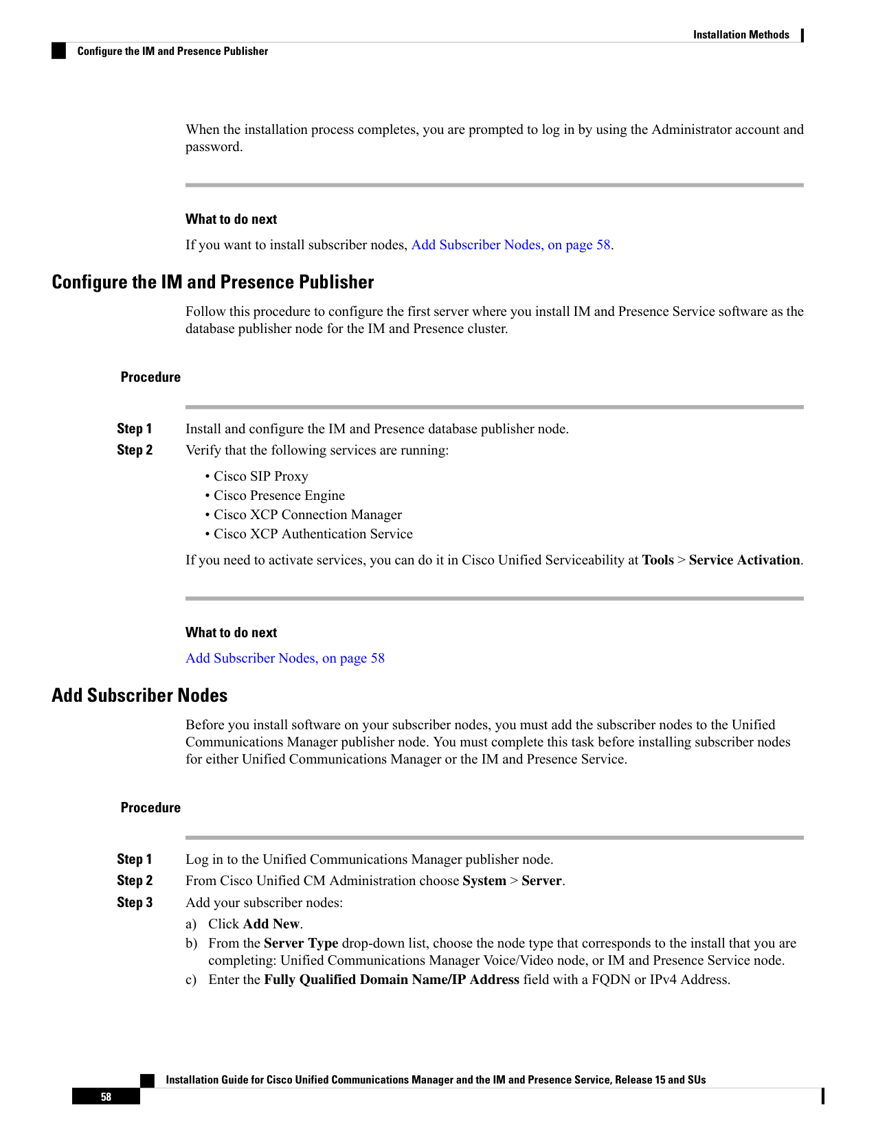
Page 65
Note
Do not use single quotes (' ') in the Description field while adding the node details.
d) Optional. If you are deploying IPv6, enter an IPv6 Address.
e)
Click Save.
f)
Repeat these steps for each subscriber node that you want to add.
Step 4
(IM and Presence Service only) Add your Presence Redundancy Groups in order to define your subclusters.
a)
From Cisco Unified CM Administration, choose System > Presence Redundancy Groups.
b) Click Add New.
c)
Enter a Name and Description for the group.
d) From the Server drop-down list, choose the IM and Presence Service nodes that you want to add to this
group.
e)
Click Save.
f)
Repeat this procedure until you've created your groups. You can have up to three Presence Redundancy
Groups in a cluster, with each group consisting of two IM and Presence Service nodes.
What to do next
Install Subscriber Nodes
Install Subscriber Nodes
Use this procedure if you want to install subscriber nodes for Unified Communications Manager or the IM
and Presence Service.
Before you begin
Before you install software for either Unified Communications Manager or IM and Presence Service subscriber
nodes, you must add the node to the Cisco Unified Communications Manager publisher node. For details,
Add Subscriber Nodes, on page 58.
Procedure
Step 1
If you have configured Network Time Protocol on the publisher node, ensure that it is synchronized with an
NTP server before you install a subscriber node. From the Command Line Interface on the publisher node,
enter utils ntp status. Ensure that the output indicates that the node is synchronized with an NTP
server.
Note
If the publisher node is not synchronized with an NTP server, installation of the subscriber node will fail.
Step 2
On the First Node Configuration window, read the Warning and make sure that you have correctly configured
the first node as the publisher node. To continue with the installation of the subscriber node, click OK.
The Network Connectivity Test Configuration window displays.
Step 3
During installation of a subscriber node, the system checks to ensure that the subscriber node can connect to
the publisher node.
Installation Guide for Cisco Unified Communications Manager and the IM and Presence Service, Release 15 and SUs
59
Installation Methods
Install Subscriber Nodes
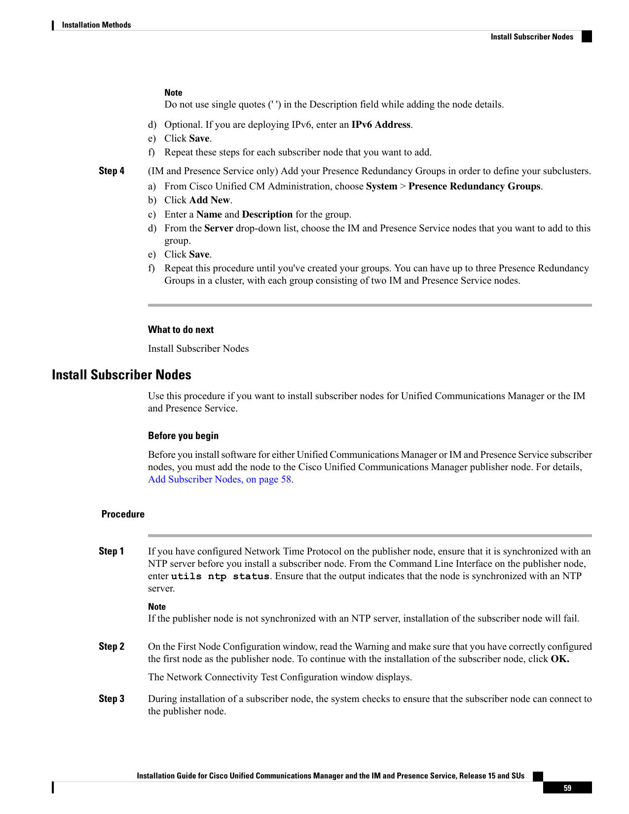
Page 66
• To pause the installation after the system successfully verifies network connectivity, choose Yes.
• To continue the installation with a pause, choose No.
The First Node Access Configuration window displays.
Step 4
Enter the publisher node connectivity information and choose OK.
The system checks for network connectivity.
If you chose to pause the system after the system successfully verifies network connectivity, the Successful
Connection to First Node window displays. Choose Continue.
Note
If the network connectivity test fails, the system always stops and allows you to go back and reenter the
parameter information.
The SMTP Host Configuration window displays.
Step 5
If you want to configure an SMTP server, choose Yes and enter the SMTP server name.
Note
To use certain operating system features, you must configure an SMTP server; however, you can also configure
an SMTP server later by using the operating system GUI or the command line interface.
The Platform Configuration Confirmation window displays.
Step 6
Choose OK to start installing the software or choose Back to change the configuration.
Step 7
When the installation process completes, you get prompted to log in by using the Administrator account and
password.
What to do next
If you have just installed a Unified Communications Manager cluster and you want to install the IM and
Presence Service on the same cluster in a standard IM and Presence deployment (as opposed to a central IM
and Presence cluster deployment), return to Attended Installation, on page 48 in order to install the IM and
Presence Service cluster.
Otherwise, proceed to the postinstallation tasks:
• Postinstall Tasks for VMware vSphere ESXi, Cisco NFVIS-for-UC, and Nutanix AHV, on page 81
• Postinstall tasks for the IM and Presence Service (VMware vSphere ESXi, Cisco NFVIS-for-UC, and
Nutanix AHV), on page 91
Touchless Installation Task Flow for ESXi
Complete these tasks to install your Unified Communications Manager and IM and Presence Service node or
clusters in a single process via the touchless installation method.
Before you begin
Preinstall Tasks for Unified Communications Manager on VMware vSphere ESXi, on page 35
Installation Guide for Cisco Unified Communications Manager and the IM and Presence Service, Release 15 and SUs
60
Installation Methods
Touchless Installation Task Flow for ESXi
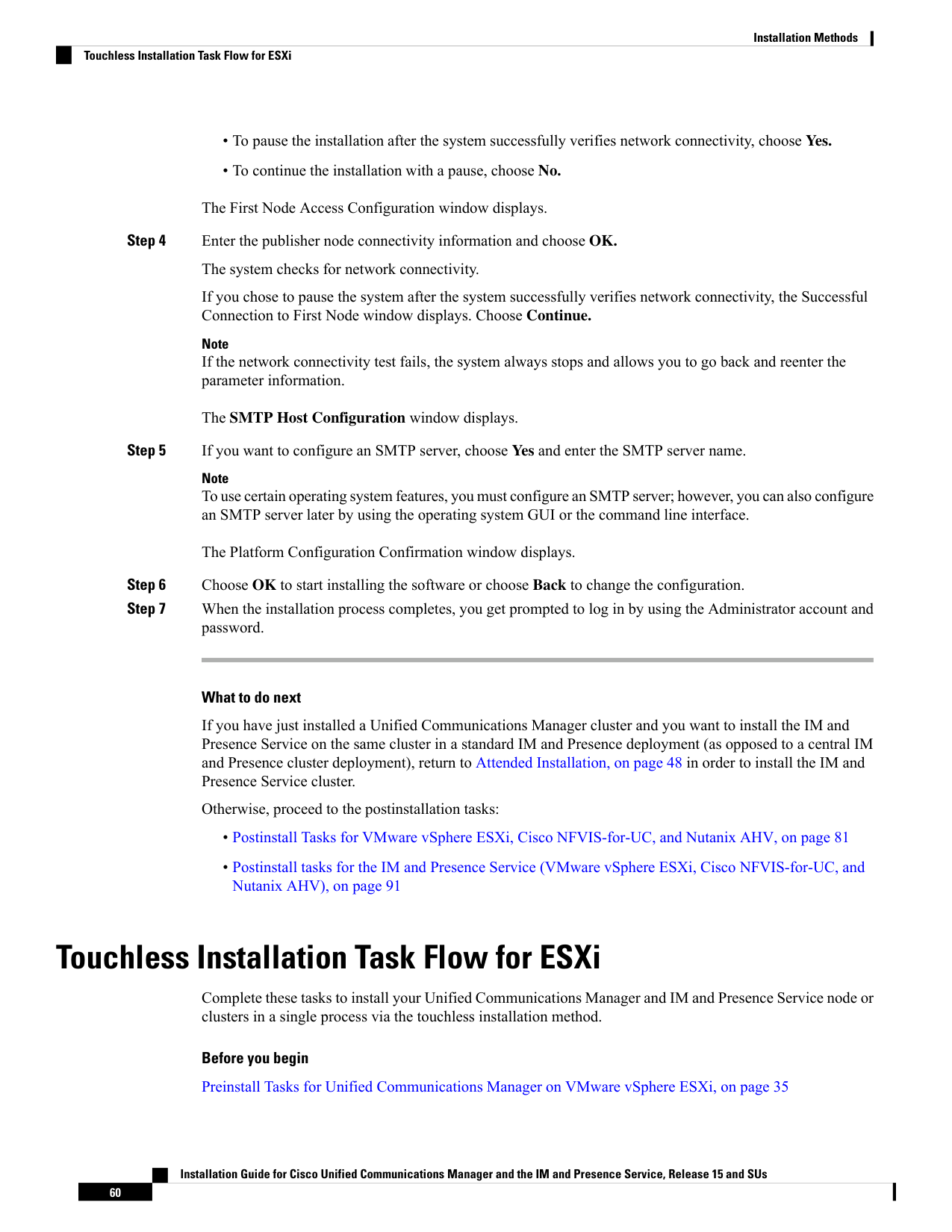
Page 67
Preinstall Tasks for IM and Presence Service on VMware vSphere ESXi, on page 39
Procedure
Purpose
Command or Action
Use this procedure to generate the configuration
files (clusterconfig.xml and platformconfig.xml)
Generate Answer Files for Touchless Install,
on page 61
Step 1
with your network settings. The touchless install
process uses these files to install and configure
a single node or the various cluster nodes.
Use this procedure to create ISO images from
the answer files. You use this ISO image in your
touchless installation.
Generate ISO Images, on page 62
Step 2
Use this procedure to upload the ISO images to
the datastore.
Upload ISO Image to Datastore, on page 63
Step 3
Use this procedure to mount the UC application
ISO images on their corresponding VM.
Mount ISO Image to VM, on page 63
Step 4
Begin the single node or cluster installation.
You can kick off all node installations
simultaneously.
Run Touchless Install, on page 64
Step 5
Generate Answer Files for Touchless Install
Use this procedure to generate answer files for your touchless installation of your cluster. The answer files
(clusterconfig.xml and platformconfig.xml) contain the configuration information that the install process
installs and configures on each cluster node.
Before you begin
You must have already planned your network topology, including addresses for your Unified Communications
Manager and IM and Presence Service cluster nodes.
Procedure
Step 1
Log in to the Cisco Unified Communications Answer File Generator application at https://www.cisco.com/c/
en/us/applicat/content/cuc-afg/index.html.
Step 2
In the Hardware section, choose Virtual Machine.
Step 3
From the Product section, select the product and version that you want to install.
Step 4
In the Software Location of Data to Import section, check the Configure Software Location of Data to
Import check box to configure Remote SFTP server details only if you choose to install using the Fresh Install
with Data Import. Else ignore this step and proceed to step 5. For more details, see Install with Data Import,
on page 75.
Installation Guide for Cisco Unified Communications Manager and the IM and Presence Service, Release 15 and SUs
61
Installation Methods
Generate Answer Files for Touchless Install
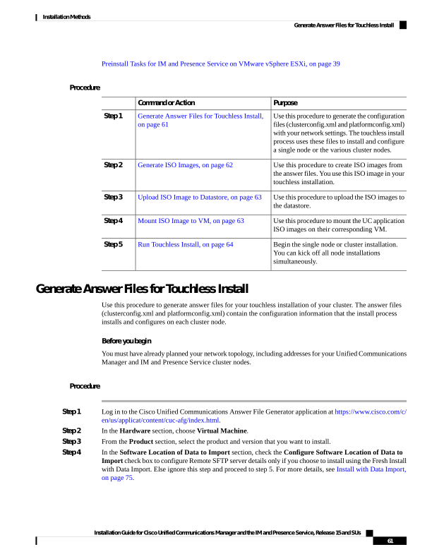
Page 68
By checking the Configure Software Location of Data to Import check box it disables, Administrator
Credentials, Security Password, Application User Credentials fields. These details are imported from source
node data during installation. Enter the following fields:
• Remote Server Name or IP—The Secure FTP (SFTP) server that stores the source cluster's exported
data.
• Export Data Directory—Directory path of the server containing export data.
• Remote Server Login ID—Allows data retrieval of the remote SFTP server.
• Remote Server Password—Can contain alphanumeric characters, hyphens, and underscores.
Step 5
Complete the remaining fields under Clusterwide Configuration with your cluster configuration details.
Step 6
Complete the fields in the Primary Node Configuration with configuration details for the publisher node.
Step 7
Check the Dynamic Cluster Config Enable check box and enter a value, in hours, for the Dynamic cluster
Config Timer.
Note
This check box must be checked if you want to install your full cluster in a single process. Otherwise, you
will need to either configure this option later through the CLI, or add your subscriber nodes manually after
the publisher node installs.
Step 8
Under Secondary Node Configuration, enter the node details for your first subscriber node and click Add
Secondary Node.
Step 9
Add all your subscriber nodes.
Step 10
Add all your cluster nodes and click Generate Answer files.
Step 11
Download the answer files to your computer.
Step 12
Repeat this procedure to generate answer files for the IM and Presence Service cluster.
Generate ISO Images
Use this procedure to create ISO images from the answer files. You will use the ISO images in your touchless
installation.
This procedure describes how to use WinImage to create ISO images. You can download WinImage from
https://www.winimage.com/download.htm.
Note
Procedure
Step 1
From WinImage, choose File > New.
Step 2
From the Standard format, choose 1.44 MB and click OK.
Step 3
Navigate to the Menu Image, choose Inject and select the platformConfig.xml file.
Step 4
When prompted to inject the file into WinImage, click Yes.
Step 5
Choose File > Save As.
Installation Guide for Cisco Unified Communications Manager and the IM and Presence Service, Release 15 and SUs
62
Installation Methods
Generate ISO Images


Page 69
Step 6
Save the file as an ISO image (.iso file) using the following naming conventions:
• Unified Communications Manager—ucm.iso
• IM and Presence Service—imp.iso
Step 7
Repeat these steps for both the Unified Communications Manager cluster and the IM and Presence Service
cluster.
Upload ISO Image to Datastore
Use this procedure to upload the ISO image to the datastore.
Procedure
Step 1
Start the vSphere client.
Step 2
Select the Configuration tab.
Step 3
Select Storage.
Step 4
Right-click on a datastore and Browse the datastore.
Step 5
Navigate to the destination directory and click the Upload files to this datastore icon.
Step 6
Upload the ISO images to your local folder.
Step 7
At the Upload/Download warning, click Yes.
Step 8
Close the Datastore Browser window.
Mount ISO Image to VM
Use this procedure to mount the UC application ISO images on their corresponding VM.
Procedure
Step 1
In the vSphere client, choose the virtual machine.
Step 2
Open VMware Remote Console (VMRC), and click the CD/DVD Drive 2.
Step 3
Browse to the datastore and locate the ISO image.
Step 4
Select the file and click OK.
Step 5
Under Device Status, enable the Connected and Connect at power on option.
Step 6
Click the Options tab. Under Boot Options, check Force entry to BIOS and click OK.
Step 7
Repeat this procedure for each VM on which you want to install a node.
Installation Guide for Cisco Unified Communications Manager and the IM and Presence Service, Release 15 and SUs
63
Installation Methods
Upload ISO Image to Datastore
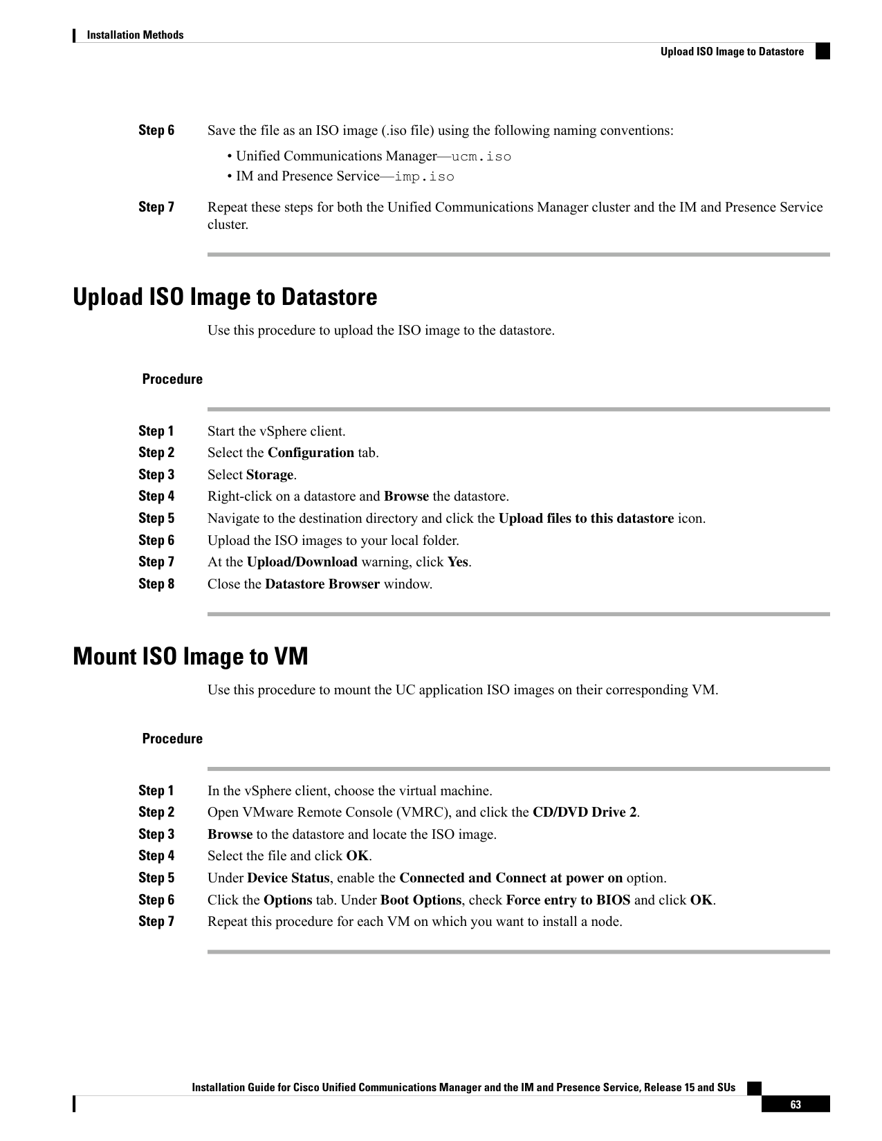
Page 70
Run Touchless Install
After you have mounted your ISO image to your application VMs, run the touchless installation process. You
can install all nodes simultaneously.
Procedure
Step 1
In vSphere client, right-click the VM and select Open Console. A console window opens.
Step 2
Click the Power On icon in the console tool bar to power on the virtual machine.
Step 3
When the BIOS screen appears, configure the following boot order:
a)
CD-Rom
b) Hard Drive
c)
Removable Devices
d) Network
Step 4
Save the settings and exit from the console. The installation commences immediately.
Step 5
Repeat these steps for each cluster node. All cluster nodes may install in parallel; you don't have to install
them serially.
Step 6
After to emphasize the completion of an activity, remove the ISO configurations from the virtual machines.
Touchless Installation Task Flow For Cisco NFVIS-for-UC
Complete these tasks to install your Unified Communications Manager and IM and Presence Service node or
clusters in a single process via the touchless installation method.
Before you begin
Preinstall Tasks for Cisco Unified Communications Manager on Cisco NFVIS-for-UC, on page 37
Preinstall Tasks for IM and Presence Service on Cisco NFVIS-for-UC, on page 40
Procedure
Purpose
Command or Action
Use this procedure to generate the configuration
files (clusterconfig.xml and platformconfig.xml)
Generate Answer Files for Touchless Install
Cisco NFVIS-for-UC, on page 65
Step 1
with your network settings. The touchless install
process uses these files to install and configure
a single node or the various cluster nodes.
Use this procedure to create ISO images from
the answer files. You use this ISO image in your
touchless installation.
Generate ISO Images, on page 66
Step 2
Installation Guide for Cisco Unified Communications Manager and the IM and Presence Service, Release 15 and SUs
64
Installation Methods
Run Touchless Install
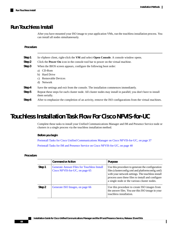
Page 71
Purpose
Command or Action
Use this procedure to upload the ISO images to
the datastore.
Upload ISO Image to Datastore, on page 66
Step 3
Use this procedure to deploy the VM. After
deployment, the installation starts automatically.
Deploy VM via NFVIS Portal, on page 68
Step 4
Generate Answer Files for Touchless Install Cisco NFVIS-for-UC
Use this procedure to generate answer files for your touchless installation of your cluster. The answer files
(clusterconfig.xml and platformconfig.xml) contain the configuration information that the install process
installs and configures on each cluster node.
Before you begin
You must have already planned your network topology, including addresses for your Unified Communications
Manager and IM and Presence Service cluster nodes.
Procedure
Step 1
Log in to the Cisco Unified Communications Answer File Generator application at https://www.cisco.com/c/
en/us/applicat/content/cuc-afg/index.html.
Step 2
In the Hardware section, choose Virtual Machine.
Step 3
From the Product section, select the product and version that you want to install.
Step 4
In the Software Location of Data to Import section, check the Configure Software Location of Data to
Import check box to configure Remote SFTP server details only if you choose to install using the Fresh Install
with Data Import. Else ignore this step and proceed to step 5. For more details, see Install with Data Import,
on page 75.
By checking the Configure Software Location of Data to Import check box it disables, Administrator
Credentials, Security Password, Application User Credentials fields. These details are imported from source
node data during installation. Enter the following fields:
• Remote Server Name or IP—The Secure FTP (SFTP) server that stores the source cluster's exported
data.
• Export Data Directory—Directory path of the server containing export data.
• Remote Server Login ID—Allows data retrieval of the remote SFTP server.
• Remote Server Password—Can contain alphanumeric characters, hyphens, and underscores.
Step 5
Complete the remaining fields under Clusterwide Configuration with your cluster configuration details.
Step 6
Complete the fields in the Primary Node Configuration with configuration details for the publisher node.
Step 7
Check the Dynamic Cluster Config Enable check box and enter a value, in hours, for the Dynamic cluster
Config Timer.
Note
Installation Guide for Cisco Unified Communications Manager and the IM and Presence Service, Release 15 and SUs
65
Installation Methods
Generate Answer Files for Touchless Install Cisco NFVIS-for-UC
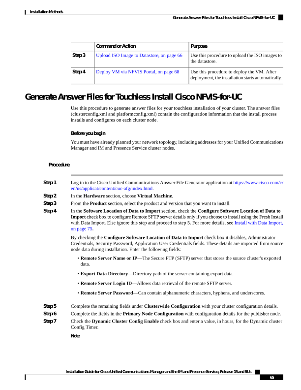
Page 72
This check box must be checked if you want to install your full cluster in a single process. Otherwise, you
will need to either configure this option later through the CLI, or add your subscriber nodes manually after
the publisher node installs.
Step 8
Under Secondary Node Configuration, enter the node details for your first subscriber node and click Add
Secondary Node.
Step 9
Add all your subscriber nodes.
Step 10
Add all your cluster nodes and click Generate Answer files.
Step 11
Download the answer files to your computer.
Step 12
Repeat this procedure to generate answer files for the IM and Presence Service cluster.
Generate ISO Images
Use this procedure to create ISO images. You will use the ISO images in your touchless installation.
This procedure describes how to use AnyBurn Tool to create ISO images. You can download any free version
from https://www.anyburn.com/download.php.
Note
NFVIS does not support ISO images created with the WinImage tool because WinImage does not generate
ISO files in the true ISO 9660 format required by NFVIS.
Note
Procedure
Step 1
Open any AnyBurn tool.
Step 2
From the options, select Create image file from files/folders.
Step 3
Click Add and include all the files that you want to include in the ISO.
Step 4
To create a destination and image name, select the path where you want to save the new ISO file and enter
the required file name.
Step 5
Click Create Now to generate the ISO file.
Upload ISO Image to Datastore
Collaboration applications require registration of both the ISO image (installation media) and the OVA file
(metadata). You must upload both the files at the same time. NFVIS supports two registration methods:
• Local Registration: Upload files directly from your computer.
• Remote Registration: Download files from a remote server using HTTP, HTTPS, FTP, or SCP.
Use this procedure to upload the ISO image to the datastore.
Installation Guide for Cisco Unified Communications Manager and the IM and Presence Service, Release 15 and SUs
66
Installation Methods
Generate ISO Images

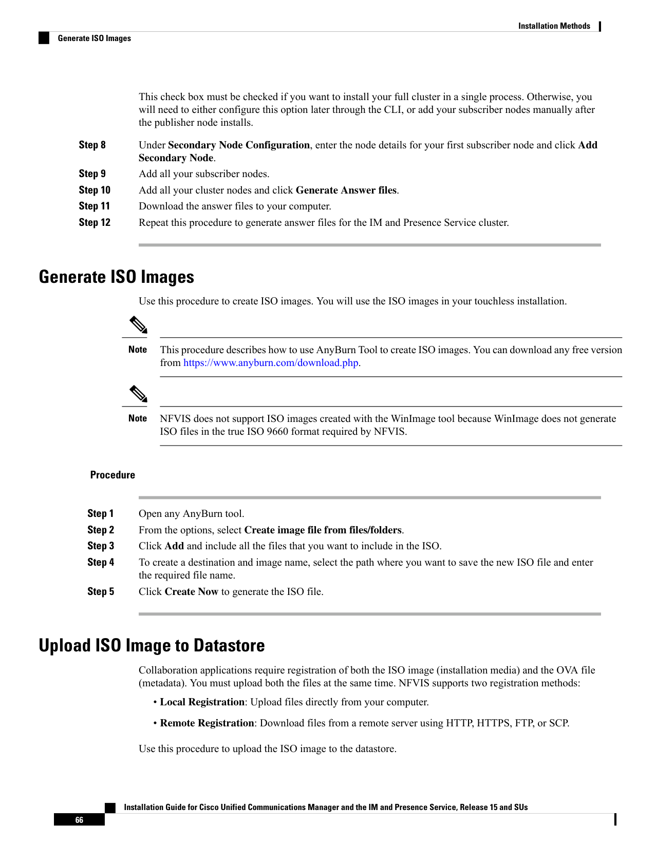
Page 73
Procedure
Step 1
Use this method when the ISO and OVA files are available on your local computer. To upload an image using
the local registration method, perform the following:
a)
Navigate to Configuration > Virtual Machine > Images > Image Repository.
b) To upload the ISO image, click Upload and select the ISO file from your local file system. For example:
Bootable_UCSInstall_UCOS_15.0.1.iso.
c)
To configure the Image Properties, enter a pre-populated name in the Image Name to a descriptive name.
For example, cucm-15.0.1. Also, select a VM Type from the drop-down list. If your application type is
not listed, select OTHER.
d) To upload an OVA Metadata, select the Metadata checkbox, click Upload OVA, and select the OVA
file. For example, cucm_15.0_vmv17_v1.2.sha512.ova.
e)
To configure additional options, select the Dedicated Cores check box (recommended for production
environments). This allocates dedicated CPU cores to the VM for improved performance.
f)
To submit the registration, click the Upload File button.
NFVIS performs the following:
• Upload the ISO image
• Upload and parse the OVA file
• Register the image
• Automatically create profiles/flavors from OVA metadata
g) To verify registration, wait for the process to complete. The image should appear in the Image Repository
with the status Active. Verify that flavors are populated from the OVA file.
Step 2
Use this method when files are hosted on a remote server (HTTP, HTTPS, FTP, or SCP). To upload an image
using the remote registration method, perform the following:
a)
Navigate to Configuration > Virtual Machine > Images > Image Repository.
b) To select the Remote Registration, click Register Image and select Remote Image Registration option.
c)
To configure the Image Details, enter a descriptive name in the Image Name field. For example,
cucm-15.0.1.
d) To configure the Remote Server Connection Protocol, enter the following details:
• Protocol: Select from the drop-down list (HTTP/HTTPS/FTP/SCP).
• IP Address: Enter the server hostname or IP address.
• Image File Path: Enter the directory path to the ISO file with the image name. For example:
/home/user/images/Bootable_UCSInstall_UCOS_15.0.1.14900-42.sha512.iso
e)
Enter the Configure Authentication details for FTP/SCP (only).
• Username: Enter the username for the remote server.
• Password: Enter the password.
f)
To upload an OVA Metadata, select the Metadata checkbox, and enter the OVA File Path name. For
example, /home/user/images/cucm_15.0_vmv17_v1.2.sha512.ova.
Installation Guide for Cisco Unified Communications Manager and the IM and Presence Service, Release 15 and SUs
67
Installation Methods
Upload ISO Image to Datastore

Page 74
Note
The OVA file must be on the same server as the ISO file. Different remote servers for the ISO and OVA
files are not supported.
g) To configure additional options, select the Dedicated Cores check box if necessary.
h) To submit the registration, click the Submit button.
NFVIS performs the following:
• Download the ISO image from the remote server
• Upload and parse the OVA file
• Register the image
• Automatically create profiles/flavors from OVA metadata
i)
To verify registration, wait for the process to complete. The image should appear in the Image Repository
with the status Active. Verify that flavors are populated from the OVA file.
Note
Downloading large files may take several minutes.
Deploy VM via NFVIS Portal
Use this procedure to deploy the VM instance.
Procedure
Step 1
Navigate to Configuration > Deploy to deploy a new virtual machine.
Step 2
Select an option from the VM. If your application type is not listed, select OTHER. If necessary, you can
change the name of the VM Type created.
Step 3
Choose the required image from the drop-down list. Images are populated based on the VM type selected.
For example, cucm-15.0.1.
Step 4
Select the appropriate flavor (with the image name) based on your sizing requirements.
Flavors are populated based on the selected image and are automatically created from the OVA file during
image registration.
Step 5
(Optional) Enter the Group Name, VNC Password, Deployment Disk, and Low Latency (TRUE).
Step 6
To configure Network Connections, perform the following in the Network Design section:
• Locate the VM icon on the canvas.
• Drag a line from the VM to the desired network.
• Connect to the appropriate network(s) for your deployment. Enter the directory path to the ISO file.
• Add additional networks as required.
Installation Guide for Cisco Unified Communications Manager and the IM and Presence Service, Release 15 and SUs
68
Installation Methods
Deploy VM via NFVIS Portal
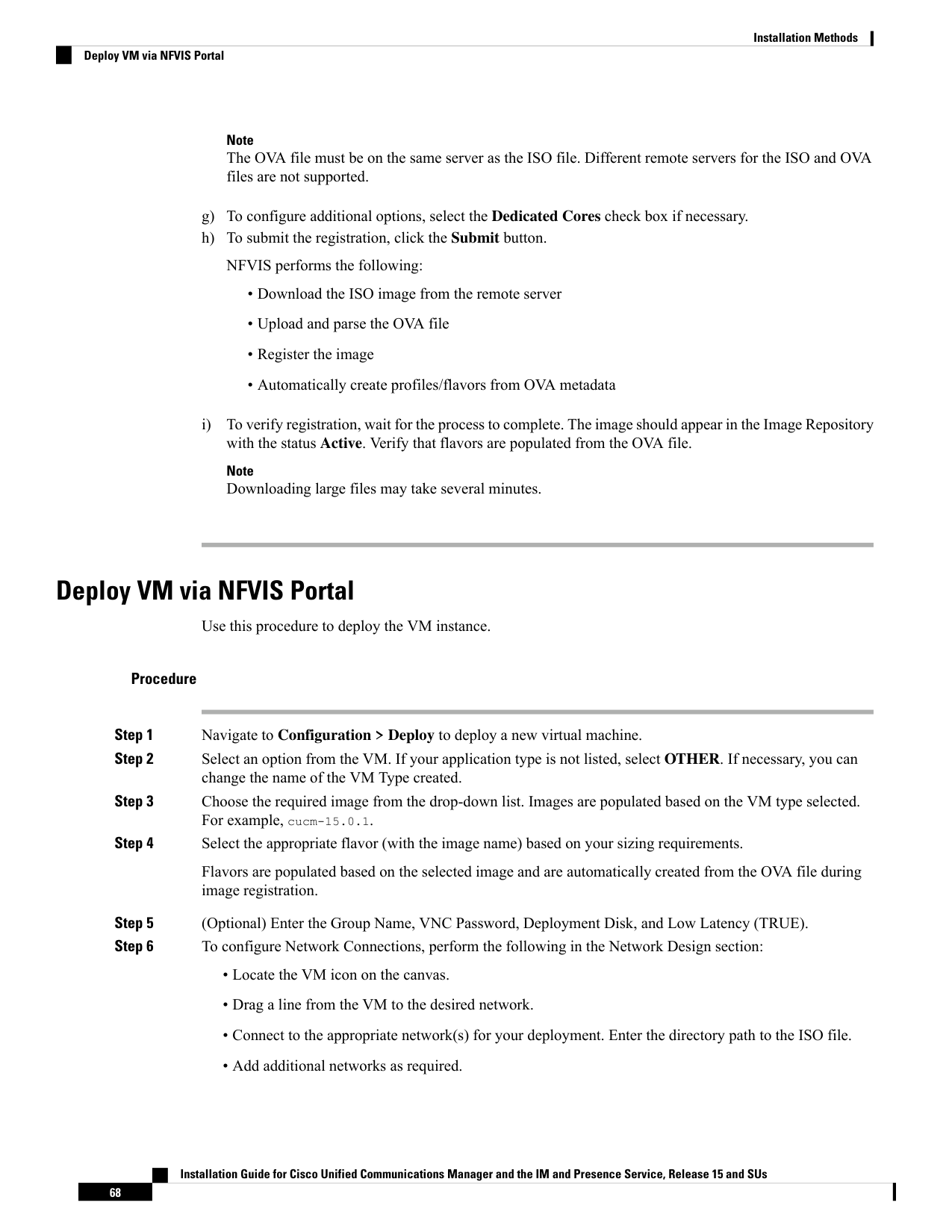
Page 75
Step 7
To attach the bootstrap ISO, select the Bootstrap ISO check box, click Upload, and select your Day 0
configuration ISO.
Step 8
To deploy the VM, click the Deploy button.
The system will validate the configuration. If validation errors occur, they will be displayed for correction.
Step 9
Navigate to Configuration > Virtual Machine > Manage to monitor the deployment.
Step 10
To access the VM console, once the VM is in ACTIVE state, click the Terminal button in the VM row.
Monitor the installation progress via the console.
Follow the application-specific installation prompts.
Touchless Installation Task Flow for Nutanix AHV
Complete these tasks to install your Unified Communications Manager and IM and Presence Service node or
clusters in a single process via the touchless installation method.
Before you begin
Preinstall Tasks for Cisco Unified Communications Manager on Nutanix AHV, on page 38
Preinstall Tasks for IM and Presence Service on Nutanix AHV, on page 41
Procedure
Purpose
Command or Action
Use this procedure to generate the configuration
files (clusterconfig.xml and platformconfig.xml)
Generate Answer Files for Touchless Install for
Nutanix AHV, on page 70
Step 1
with your network settings. The touchless install
process uses these files to install and configure
a single node or the various cluster nodes.
Use this procedure to create ISO images from
the answer files. You use this ISO image in your
touchless installation.
Generate ISO Images, on page 71
Step 2
Use this procedure to upload the ISO images to
the datastore.
Upload ISO Image to Nutanix Cluster, on page
71
Step 3
Begin the single node or cluster installation.
You can kick off all node installations
simultaneously.
Power On the Virtual Machine, on page 72
Step 4
Installation Guide for Cisco Unified Communications Manager and the IM and Presence Service, Release 15 and SUs
69
Installation Methods
Touchless Installation Task Flow for Nutanix AHV
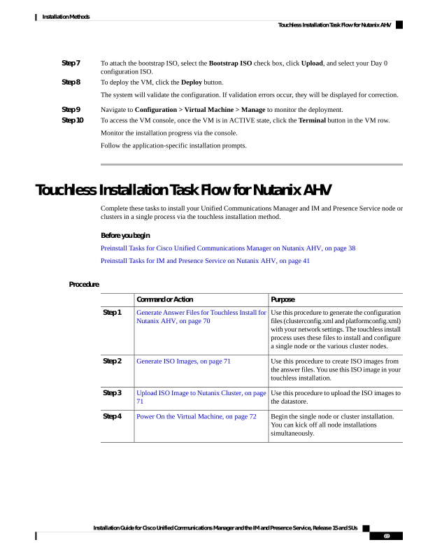
Page 76
Generate Answer Files for Touchless Install for Nutanix AHV
Use this procedure to generate answer files for your touchless installation of your cluster. The answer files
(clusterconfig.xml and platformconfig.xml) contain the configuration information that the install process
installs and configures on each cluster node.
Before you begin
You must have already planned your network topology, including addresses for your Unified Communications
Manager and IM and Presence Service cluster nodes.
Procedure
Step 1
Log in to the Cisco Unified Communications Answer File Generator application at https://www.cisco.com/c/
en/us/applicat/content/cuc-afg/index.html.
Step 2
In the Hardware section, choose Virtual Machine.
Step 3
From the Product section, select the product and version that you want to install.
Step 4
In the Software Location of Data to Import section, check the Configure Software Location of Data to
Import check box to configure Remote SFTP server details only if you choose to install using the Fresh Install
with Data Import. Else ignore this step and proceed to step 5. For more details, see Install with Data Import,
on page 75.
By checking the Configure Software Location of Data to Import check box it disables, Administrator
Credentials, Security Password, Application User Credentials fields. These details are imported from source
node data during installation. Enter the following fields:
• Remote Server Name or IP—The Secure FTP (SFTP) server that stores the source cluster's exported
data.
• Export Data Directory—Directory path of the server containing export data.
• Remote Server Login ID—Allows data retrieval of the remote SFTP server.
• Remote Server Password—Can contain alphanumeric characters, hyphens, and underscores.
Step 5
Complete the remaining fields under Clusterwide Configuration with your cluster configuration details.
Step 6
Complete the fields in the Primary Node Configuration with configuration details for the publisher node.
Step 7
Check the Dynamic Cluster Config Enable check box and enter a value, in hours, for the Dynamic cluster
Config Timer.
Note
This check box must be checked if you want to install your full cluster in a single process. Otherwise, you
will need to either configure this option later through the CLI, or add your subscriber nodes manually after
the publisher node installs.
Step 8
Under Secondary Node Configuration, enter the node details for your first subscriber node and click Add
Secondary Node.
Step 9
Add all your subscriber nodes.
Step 10
Add all your cluster nodes and click Generate Answer files.
Step 11
Download the answer files to your computer.
Installation Guide for Cisco Unified Communications Manager and the IM and Presence Service, Release 15 and SUs
70
Installation Methods
Generate Answer Files for Touchless Install for Nutanix AHV
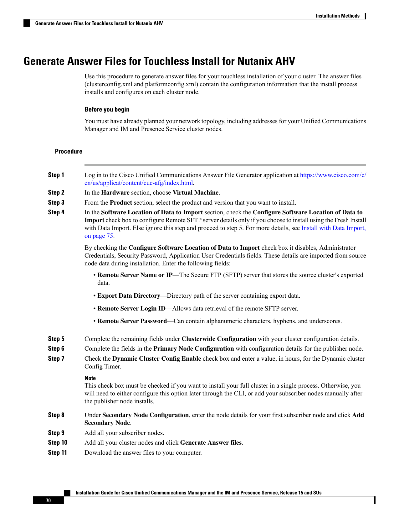
Page 77
Step 12
Repeat this procedure to generate answer files for the IM and Presence Service cluster.
Generate ISO Images
Use this procedure to create ISO images from the answer files. You will use the ISO images in your touchless
installation.
This procedure describes how to use WinImage to create ISO images. You can download WinImage from
https://www.winimage.com/download.htm.
Note
Procedure
Step 1
From WinImage, choose File > New.
Step 2
From the Standard format, choose 1.44 MB and click OK.
Step 3
Navigate to the Menu Image, choose Inject, and select the platformConfig.xml and the
clusterConfig.xml file for the Unified CM Publisher node. For Unified CM Subscriber, IM and Presence
Publisher and Subscriber, choose Inject, and select the platformConfig.xml file only.
Step 4
When prompted to inject the file into WinImage, click Yes.
Step 5
Choose File > Save As.
Step 6
Choose All files from the drop-down for the Save as type and specify the file name as an ISO image (with
.iso file extension, for example imagename.iso) using the following naming conventions:
• Unified Communications Manager—ucm.iso
• IM and Presence Service—imp.iso
Step 7
Repeat these steps for both the Unified Communications Manager cluster and the IM and Presence Service
cluster.
Upload ISO Image to Nutanix Cluster
Create ISO images for the Unified CM publisher and subscribers based on the generated answer file, and
upload the <cucm_answer_file>.iso for the publisher and subscribers to the Nutanix clusters. In case of manual
installation of Unified CM, the second CD-ROM does not need to be mounted with the <cucm_answer_file>.iso
file.
Procedure
Step 1
Download the desired version of the Unified CM bootable .iso image from the Cisco.com to your local machine.
Step 2
Log in to Nutanix Prism Central or Prism Element with your credentials.
Step 3
In the top-right corner of the Nutanix Prism Central page, click the three-line menu icon.
Installation Guide for Cisco Unified Communications Manager and the IM and Presence Service, Release 15 and SUs
71
Installation Methods
Generate ISO Images

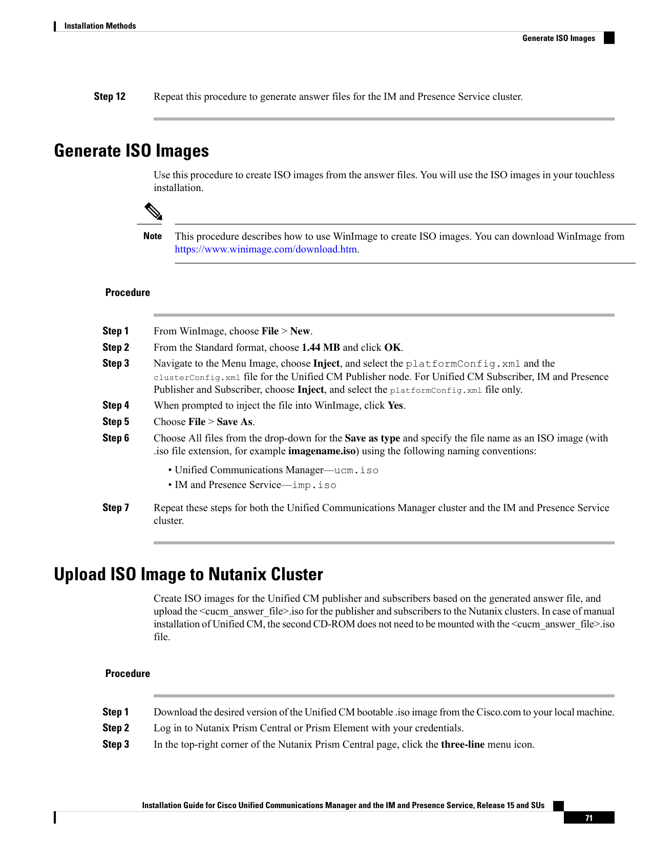
Page 78
Step 4
Click Images in the left pane, then select Add Image.
Step 5
On the Add Images page, you can either choose the Image File and click + Add File to select the locally
downloaded file to upload to the Nutanix cluster, or select the URL radio button to upload the bootable .iso
image from a remote server by providing the NFS path in the Image URL field.
Step 6
Click + Add URL and provide the authentication credentials to connect to the remote server.
Step 7
Click Next and save the changes.
Step 8
Check the status of the image upload on the Tasks page to confirm the successful upload of the .iso image to
the Nutanix cluster. For example, a URL is the following: nfs://<Host
IP>/<path>/Bootable_UCSInstall_UCOS_15.0.1.xxxxx-xx.sha512.iso.
Power On the Virtual Machine
After you have mounted your ISO image to your application VMs, run the touchless installation process. You
can install all nodes simultaneously.
Automated Installation using vApp properties and VMware OVF
Tool
This feature uses a skip-install Open Virtual Archive (OVA) file containing an application that is installed up
to the “skip” configuration point, where the application is ready to accept the configuration and complete
installation. The VMware OVF Tool is used to deploy and inject the Unified CM and IM and Presence Service
configuration parameters into the virtual machines using skip-install OVA and vApp properties without using
Answer File Generator or vFloppy images.
Deployment vApp options are available for virtual machines that are deployed from VMware Open
Virtualization Format Tool (OVF) Tool to the desktop or to the web server (Application available only on
vcenter). For a virtual machine with vApp options enabled, the vApp options are preserved when you export
the virtual machine as an OVF template. Without manual intervention from the administrators, you just need
the skip-install OVA image to install the entire Unified CM clusters. Using the vApp parameters, you simply
need to define a template and set the values of vApp Properties and inject all the details during deployment
of the skip-install OVA using the VMware OVF Tool that results in automated installation.
Fresh Install and Fresh Install with Data Import is supported using this method. You can deploy this installation
in two ways:
• Manual Installation Using vApp Options—Deploy the skip-install OVA on each node in the cluster
manually by logging into the respective VMware Embedded Host Client or vCenter Server, where the
Unified CM server configurations can be entered.
• Touchless Installation Using VM Builder and VMware OVF Tools—Run the VM Builder tool (which
is a VMware wrapper tool that is provided as part of the platform skip-install-ova rpm/tar) by passing
the Unified CM configuration parameters, skip-install OVA, and VMware Embedded Host Client or
vCenter Server details of each node in the cluster, which would perform the complete cluster installation
without manual intervention.
Installation Guide for Cisco Unified Communications Manager and the IM and Presence Service, Release 15 and SUs
72
Installation Methods
Power On the Virtual Machine
Page 79
Manual Installation Using vApp Options
This option allows you to deploy OVA manually in the VMware Embedded Host Client or vCenter Server
where OVA needs to be placed either in the desktop or to the web server.
The OVA deployment from a web server is applicable only for vCenter.
Note
While deploying skip-install OVA through vCenter, you will see additional terminologies in the First Node
Access Configuration (Set ONLY on SUBSCRIBERS) field on the customization template. For example,
First Node Access Configuration (Set ONLY on 2 settings SUBSCRIBERS). We recommend that you ignore
the term 2 settings in this field as this term is parsed from the vCenter configuration settings.
Note
This task is only supported with the VMware Embedded Host Client or vCenter Server version 7.0 U3 or 8.0
U1.
Note
Procedure
Step 1
Deploy skip-install OVA after obtaining it from Cisco License Central.
Step 2
From VMware Embedded Host Client or vCenter Server, deploy OVA from the desktop using the Browse
button or enter a URL to download and install the OVA package from the Internet.
Step 3
If the OVA is placed in a web server, enter the respective URL while deploying the OVA. For example,
http://10.xx.xx.xx/UCSInstall\_UCOS\_14.xxx.ova.
Step 4
Enter the required Unified CM configurations, skip-install OVA, VMware Embedded Host Client, or vCenter
for each node in the cluster.
The configuration is different for publisher and subscriber nodes. See the Required Installation Information
help page to fill the mandatory configuration details.
Note
With this installation method, you can add up to 5 Unified Communication Manager subscriber nodes and 5
IM and Presence Service nodes in the user interface of Unified CM publisher. If we need to add more subscribers
(Unified CM or IM and Presence Service), follow step 5 or step 6 depending on the deployment.
Step 5
To perform touchless install on entire cluster including publisher, make sure to check the Dynamic Cluster
Config Enable check box in user interface of the Unified Communication Manager publisher, and enter a
value between 1-24 in the Dynamic cluster Config Timer field.
Step 6
To install subscriber nodes in the cluster after the Unified CM publisher installation completes, perform any
one of the following:
• Enable the Dynamic Cluster Config Timer option in Unified Communication Manager publisher using
the CLI set network cluster subscriber dynamic-cluster-configuration no-of-hours|default. (OR)
Installation Guide for Cisco Unified Communications Manager and the IM and Presence Service, Release 15 and SUs
73
Installation Methods
Manual Installation Using vApp Options

Page 80
• Add your subscriber nodes manually from the user interface of the Unified CM publisher, after the
Unified CM publisher node installation completes.
Step 7
For installation using Fresh Install with Data Import, follow the instructions as described in Attended Installation
Task Flow, on page 46 from step 1 through 6 to export data from source node. See Install with Data Import,
on page 75.
Step 8
Once the OVA image is deployed successfully into the virtual machine, power on the Virtual Machine.
You will observe that the installation is in process. Repeat step 4 for each subscriber node in the cluster by
providing the IP Address and Host Name of the Unified CM publisher nodes. Subscriber nodes can be
installed parallelly by opening multiple VMware Embedded Host Clients.
Note
If DHCP is enabled for OVA deployment, ensure that you go to the edit settings of the virtual machine and
change the MAC option to manual (by default, this option is automatic) before powering-on the virtual
machine. Enter the static MAC address mapped with the IP Address and Host Name for the Unified
Communications Manager and IM and Presence Service nodes.
Touchless Installation Using VM Builder and VMware OVF Tools
This task allows to deploy skip-install OVA using the Cisco VM Builder tool, which is a wrapper tool to inject
the configurations parameters.
This task is only supported with VMware Embedded Host Client or vCenter Server version 7.0 U3 or 8.0 U1.
Note
Before you begin
• Requires a Linux server to run Cisco VM Builder and VMware OVF Tool.
The Cisco VM Builder tool (VMware wrapper tool) and the dependent tool will be bundled and provided as
.rpm file (platform-skip-install-ovftool-1.0.0.0-1.x86_64.rpm) or as a g-zipped tar file/tarball
(platform-skip-install-ovftool_v1.0.tar.gz.) See the ReadMe guide for instructions on how to install .rpm/tar.
Procedure
Step 1
Install the Cisco VM Builder tool on any Linux server. It can be an SFTP server as well.
Step 2
Copy the Unified Communications Manager and IM and Presence Service OVA image to the same server.
Step 3
Using the Cisco VM Builder tool, pass the required Unified CM configurations, skip-install OVA, and VMware
Embedded Host Client or vCenter for each node in the cluster based on the type of Install. Install can be Fresh
Install or Fresh Install with Data Import.
Configurations differ for the publisher and subscriber nodes. Use the “vmbuilder--help” option to know more
about the parameters to be used.
Note
Installation Guide for Cisco Unified Communications Manager and the IM and Presence Service, Release 15 and SUs
74
Installation Methods
Touchless Installation Using VM Builder and VMware OVF Tools

Page 81
With this installation method, you can add up to 5 Unified Communication Manager subscriber nodes and 5
IM and Presence Service subscriber nodes in the Cisco VM Builder tool of the Unified CM publisher. If we
need to add more subscribers (Unified CM or IM and Presence Service), follow step 4 or step 5 depending
on the deployment.
Step 4
To perform touchless install on entire cluster including publisher, make sure to pass the Dynamic Cluster
Config Enable parameter as True and enter a value between 1-24, in the Dynamic cluster Config Timer in
the Cisco VM Builder tool of the Unified CM publisher. For example, set the values of these parameters as:
guest.dynamic_cluster_config=True and guest.cluster_config_timer=24.
Step 5
To install subscriber nodes in the cluster after the Unified CM publisher installation completes, perform any
one of the following:
• Enable the Dynamic Cluster Config Enable option in the user interface of the Unified Communication
Manager publisher using the CLI set network cluster subscriber dynamic-cluster-configuration
no-of-hours|default. (OR)
• Add your subscriber nodes manually from the Unified CM user interface of the publisher, after the
Unified CM publisher node installation completes.
Step 6
The Cisco VM Builder tool validates the configuration values, deploys the OVA in the VMware Embedded
Host Client or vCenter Server, automatically powers on the node, and starts the installation.
See the “vmbuilder--help” option to know more about the mandatory parameters and other restrictions.
Step 7
Repeat step 3 for each subscriber node in the cluster. Subscriber nodes can be installed parallelly by opening
multiple SSH connections.
Note
DHCP is not supported for touchless installation as the automated MAC can assign any IP Address and Host
Name for the nodes.
Install with Data Import
Use the following procedure to configure Unified Communications Manager and IM and Presence Service
installation with data import from an older version of Unified CM.
See the Upgrade and Migration Guide for Cisco Unified Communications Manager and the IM and Presence
Service to refer to the supported source releases for direct migration to the 15 destination versions.
Installation Guide for Cisco Unified Communications Manager and the IM and Presence Service, Release 15 and SUs
75
Installation Methods
Install with Data Import
Page 82
• Fresh Install with Data Import does not support domain name changes. If DNS is enabled on the publisher
node of the destination cluster, the domain name must match the source cluster. If the domain name
needs to change, install the destination cluster on the publisher without the DNS enabled and then enable
DNS via the CLI after the installation is complete. The subscribers can be installed with the DNS enabled,
but ensure that the System > Server entries on the publisher node are correct before installing the
subscribers.
If you plan to change the hostname and/or IP address during the migration, the System > Server entries
must be updated on the publisher node of the destination cluster prior to installing the subscribers.
• Fresh Install with Data Import does not support installation with DHCP configuration. If DHCP is enabled
on the source cluster, install the destination cluster with Static configuration data and then configure the
DHCP later post migration.
Important
Ensure that all nodes in the cluster are exported to the SFTP server before proceeding with Fresh Install with
Data Import.
Note
Before you begin
Ensure that your source version must be Release 10.5 or higher. If your source version is not Release 12.5(1)
SU5 or higher, you need to install the latest version of the "ciscocm.DataExport" COP file on each node of
the source system.
We recommend that you have a single reliable NTP server configured for time synchronization for fresh
installations. If you configure multiple NTP servers, configure at least four to ensure that Unified CM can
determine a tie breaker when servers provide different time sources.
Note
Procedure
Step 1
Export data from the source cluster publisher node.
a)
Run the utils system upgrade dataexport initiate CLI command on each node of the desired source
system to export the data which can be imported using this procedure.
b) Enter the SFTP server information to export the data.
c)
Enter the node Hostname and IP Address (it is possible to change them at this stage.)
d) Run the utils system upgrade dataexport status to track the export status.
A new folder is created at the SFTP server with the cluster name: Publisher IP Address.
Step 2
Export data from the source cluster subscriber node.
a)
Run the utils system upgrade dataexport initiate CLI command on each node of the desired source
system to export the data which can be imported using this procedure.
b) Enter the SFTP server information to export data.
c)
Enter the node Hostname and IP Address (it is possible to change them at this stage).
Installation Guide for Cisco Unified Communications Manager and the IM and Presence Service, Release 15 and SUs
76
Installation Methods
Install with Data Import

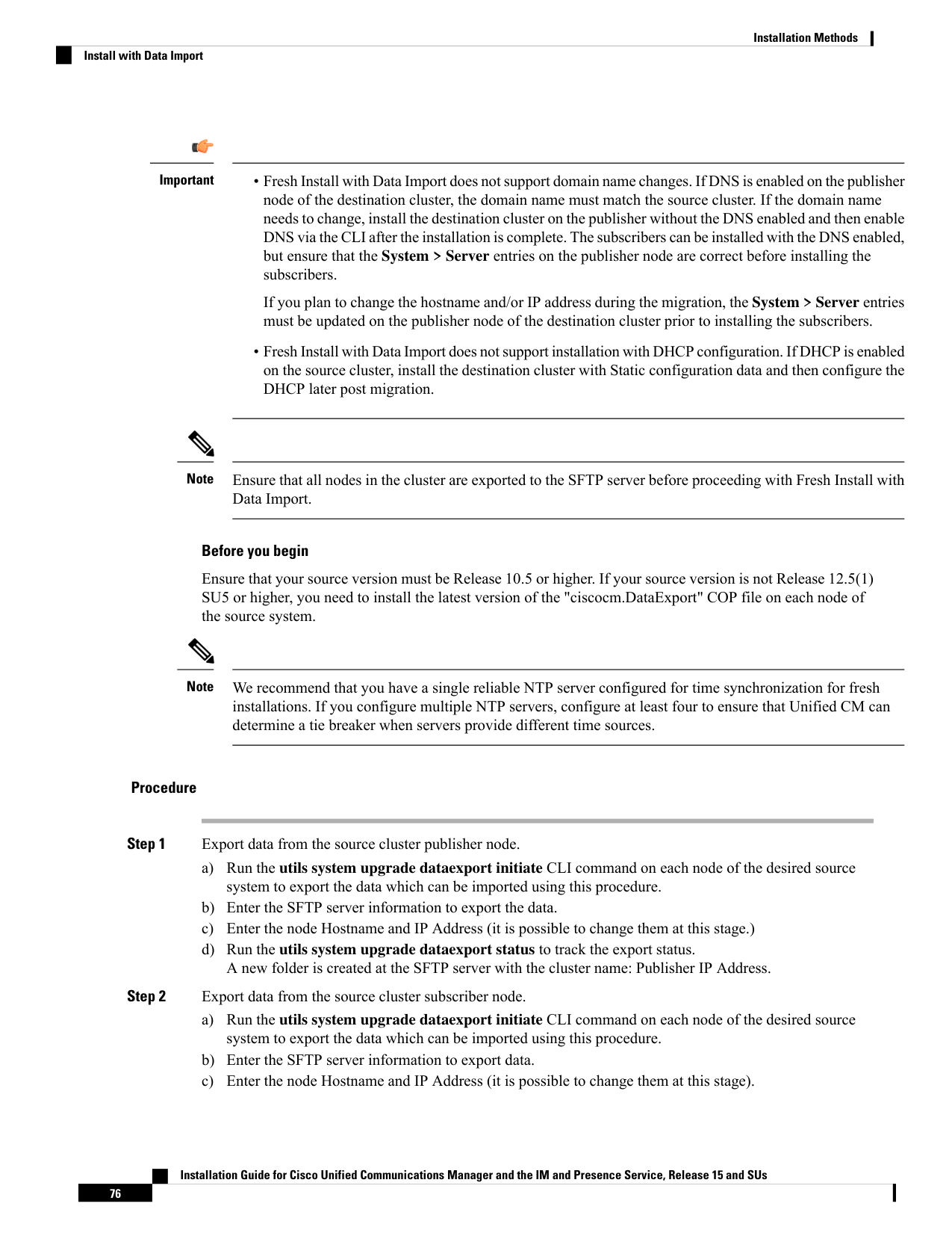
Page 83
d) Run the utils system upgrade dataexport status to track the export status.
The exported subscriber data is stored in the same cluster folder: Publisher IP Address.
Step 3
Repeat Step 2 for the remaining subscriber nodes.
Step 4
Then proceed with one of the following methods to complete installation/import.
Note
During the configuration of an IP address, if the source and destination clusters are using DHCP, ensure that
you configure a static IP address for the destination cluster. For example, the current IP address of the source
cluster.
Installation Guide for Cisco Unified Communications Manager and the IM and Presence Service, Release 15 and SUs
77
Installation Methods
Install with Data Import

Page 84
See
Installation Method
a.
Install a new publisher and import the data. To
configure Unified Communications Manager and
IM and Presence Service with Install with Data
Import follow the instructions as described in
Attended Installation, on page 48 from step 1
through 6.
b.
In the Platform Installation Wizard window,
choose Import from the various options that are
provided to import data from the SFTP server
during the Unified Communications Manager and
IM and Presence Service installation.
c.
In the import wizard, provide details for the
following information:
• Hostname, IP Address, Subnet mask, and
Gateway. This must be the same information
provided in the destination node for which
you exported the data.
• SFTP—In the export data directory, enter
the exported data folder name or cluster
information: <Publisher IP Address>.
• Confirm whether this is the First Node.
• Enter one or more NTP servers.
Note
If you are planning to use the same Hostname/IP
Address, ensure that the older publisher node is
shut down before installing a new publisher node.
d. Install a new Subscriber and import the data.
Repeat step 4 except for the First Node question.
Respond to this query with a 'No' and provide the
new publisher IP Address and hostname
information.
Note
If you are planning to use the same Hostname/IP
Address, ensure that the older publisher node is
shut down before installing a new publisher node.
Attended Install
Follow the instructions as described in Touchless
Installation Task Flow for ESXi, on page 60 from
step 1 through 5.
Touchless Install of a Single Node or a Cluster
Installation Guide for Cisco Unified Communications Manager and the IM and Presence Service, Release 15 and SUs
78
Installation Methods
Install with Data Import
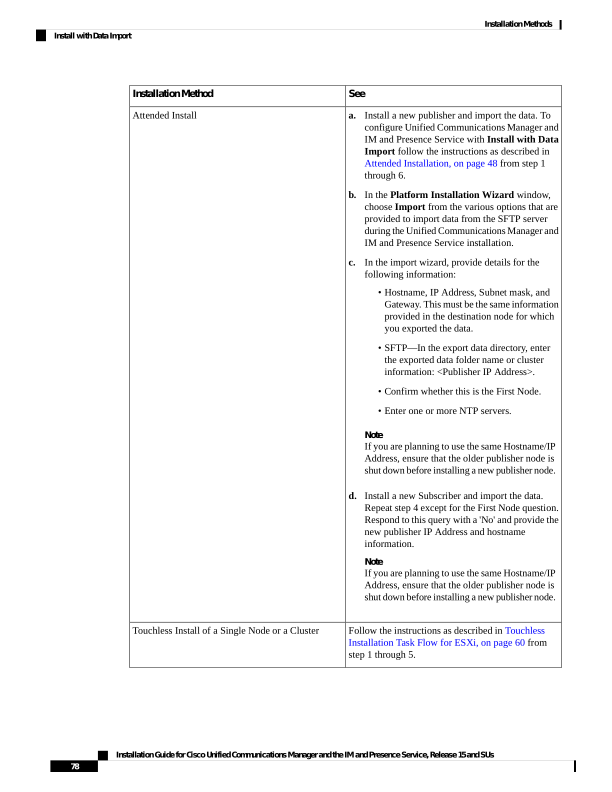
Page 85
See
Installation Method
Follow the instructions as described in Touchless
Installation Using VM Builder and VMware OVF
Tools, on page 74 from step 1 through 7.
VMware OVF Tool
Note
If you are planning to use DHCP for the cluster node IP addresses, enable this configuration using the set
network dhcp eth0 command.
Add a New Node to an Existing Cluster
To add a new Unified Communications Manager or IM and Presence Service subscriber node to an existing
cluster, you can use either the basic attended Installation or Installation Using VM Builder and VMware OVF
Tools methods to add and install the node. Any new nodes that you add must be configured as subscriber
nodes.
Attended Installation
For attended installations of additional Unified Communications Manager or IM and Presence Service cluster
nodes, complete the following tasks:
Description
Procedure
For details, see the "Manage Backups" chapter
of the Administration Guide for Cisco Unified
Communications Manager.
Run a full backup of the cluster.
Step 1
Begin the installation process.
Attended Installation, on page 48
Step 2
Continue with the Attended Installation
process by configuring your installation.
Configure Attended Installation, on page 53
Step 3
Add subscriber nodes to Unified
Communications Manager publisher.
Add Subscriber Nodes, on page 58
Step 4
Install software on your subscriber nodes.
Install Subscriber Nodes, on page 59
Step 5
Touchless Installation
For Touchless installations of additional Unified Communications Manager or IM and Presence Service cluster
nodes or a single node, complete the Touchless Installation tasks for the respective hypervisor selected. See
Installation Methods, on page 43.
Installation Guide for Cisco Unified Communications Manager and the IM and Presence Service, Release 15 and SUs
79
Installation Methods
Add a New Node to an Existing Cluster
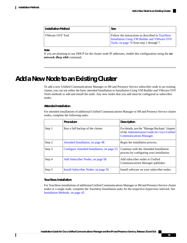
Page 86
Notes for Basic and Touchless Installs
After you install a new node on an existing cluster, if you plan to utilize Cisco CallManager or Cisco TFTP
services, we recommend that you restart all the phones in your cluster to get the latest ITL file. If you are
using a Certificate Trust List (CTL), you will also need to update this file manually by running the utils ctl
update CTLFile CLI command (using Tokenless CTL) or by updating the file via the CTL Client (Legacy
USB tokens). After you update the CTL file, you must restart the phones so that they can download the latest
CTL file. For additional details on the CTL File, see the “Cisco CTL Client Setup” chapter of the Security
Guide for Cisco Unified Communications Manager.
Important
• You can collect the logs from RTMT of a new node added to the existing FQDN cluster, only when you
restart the trace collection service. When you sign in to Unified RTMT without restarting the trace
collection, the following error message is displayed:
Could not connect to 'Server' <new node name>.
• If you install a new node to an existing cluster where the IM and Presence server is not upgraded to the
supported version or if the IM and Presence server has been decommissioned, the following error message
is displayed:
"Add failed. Upgrade and migration for Cisco Unified IM & Presence
Servers that are associated with this cluster appears to be pending
(not complete). Please make sure upgrade and migration of all IM &
Presence servers is completed successfully before adding servers to
this cluster. Please check for any unused IM & Presence Application
Servers and delete them”.
Note
A touchless install cannot be used to simultaneously install multiple Unified Communications Managers and
multiple IM and Presence Service nodes. The following scenarios are supported:
• Installing only multiple Unified Communications Manager nodes
• Installing only one Unified Communications Manager node (publisher) and multiple and IM and Presence
Service nodes
If you need to simultaneously install multiple Unified Communications Manager and IM and Presence Service
nodes, you must use one of the above scenarios and install additional nodes manually.
Note
Installation Guide for Cisco Unified Communications Manager and the IM and Presence Service, Release 15 and SUs
80
Installation Methods
Add a New Node to an Existing Cluster

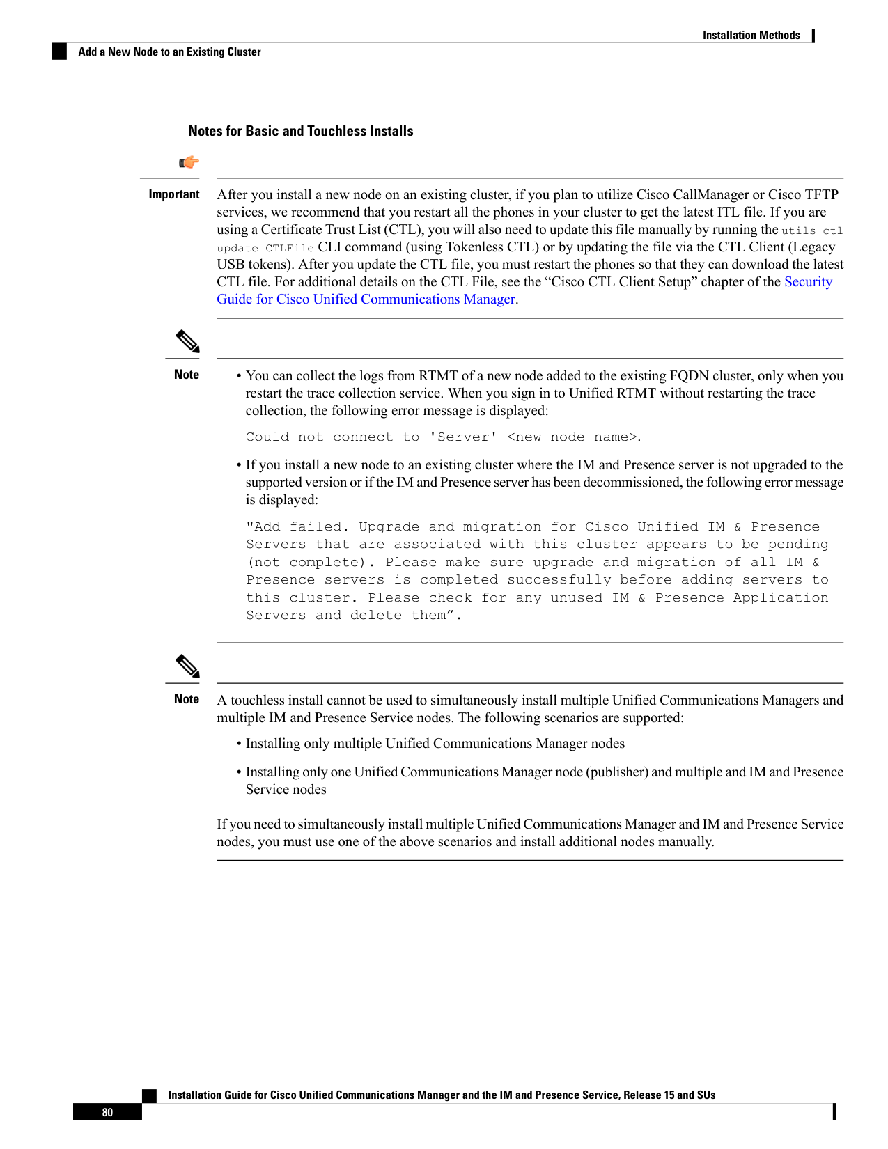
Page 87
C H A P T E R 5
Postinstallation Tasks
• Postinstall Tasks for VMware vSphere ESXi, Cisco NFVIS-for-UC, and Nutanix AHV, on page 81
• Postinstall tasks for the IM and Presence Service (VMware vSphere ESXi, Cisco NFVIS-for-UC, and
Nutanix AHV), on page 91
• Where to Go Next, on page 93
PostinstallTasksforVMwarevSphereESXi,CiscoNFVIS-for-UC,
and Nutanix AHV
Procedure
Purpose
Command or Action
You can download the Release Notes from the
below URL. Make sure that you understand
Read the Release Notes and any Readme files
that come with your release.
Step 1
the features for your release and any COP file
requirements.
https://www.cisco.com/c/en/us/support/
unified-communications/
unified-communications-manager-callmanager/
products-release-notes-list.html
Before you attempt to upgrade any cluster
nodes or install any COP files on the cluster
Configure Software Location on cluster nodes
that will be used for future upgrades and COP
Installs.
Step 2
nodes, all cluster nodes need to have their
Software Location fields configured. For more
information on configuring software location
details, see the 'Configure Cluster Software
Location' section in the Upgrade and Migration
Guide for Cisco Unified Communications
Manager and the IM and Presence Service
from Releases 12.5(1)SU6 and 14SU2
onwards.
Installation Guide for Cisco Unified Communications Manager and the IM and Presence Service, Release 15 and SUs
81

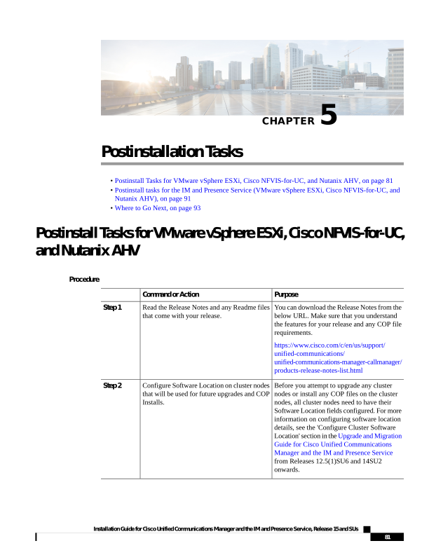
Page 88
Purpose
Command or Action
We recommend that you reset your application
user passwords post installation.
Reset Application User Passwords, on page
83
Step 3
You can use the Cisco Unified Real-Time
Monitoring Tool (RTMT) to monitor Unified
Install Unified RTMT
Step 4
Communications Manager and the IM and
Presence Service in real time. See the "Install
Unified RTMT" section in the Cisco Unified
Real-Time Monitoring Tool Administration
Guide.
If you have a kernel crash, the kerneldump
utility provides a mechanism for collecting and
dumping the crash.
Enable the Kerneldump Utility, on page 84
Step 5
Verify that you have the required licenses for
your system and devices.
Install Licenses, on page 84
Step 6
We recommend performing regular backups.
You can set up automatic backups or invoke
a backup at any time.
Configure the Backup, on page 84
Step 7
Optional. The default locale is US - English.
If you want to use a different locale, download
and install it.
Install New Locales, on page 85
Step 8
You may need to install a COP file after the
installation to fix a known defect, or to enable
COP File Installation Guidelines, on page 88
Step 9
support for a custom device type that you want
to use that does not ship with Unified
Communications Manager.
If you want to use a dial plan other than the
North American Numbering Plan (the default),
you must download and install it.
Install a dial plan by completing these tasks:
Step 10
• Install a COP File, on page 88
• Install a Prebuilt Dial Plan, on page 89
• Restart the Cisco CallManager Service,
on page 89
Optional. If you want to enable security on
your system, install the Cisco CTL Client and
enable mixed mode.
Activate Security, on page 90
Step 11
Optional. If you are using a Network
Management System such as Cisco Prime
Configure the Simple Network Management
Protocol, on page 90
Step 12
Collaboration Assurance, enable the Simple
Network Management Protocol.
To change to the Guest OS version in the Cisco
Unified Communications Manager virtual
machine (VM) settings.
Change Virtual Machine Configuration
Specifications, on page 91
Step 13
Installation Guide for Cisco Unified Communications Manager and the IM and Presence Service, Release 15 and SUs
82
Postinstallation Tasks
Postinstall Tasks for VMware vSphere ESXi, Cisco NFVIS-for-UC, and Nutanix AHV
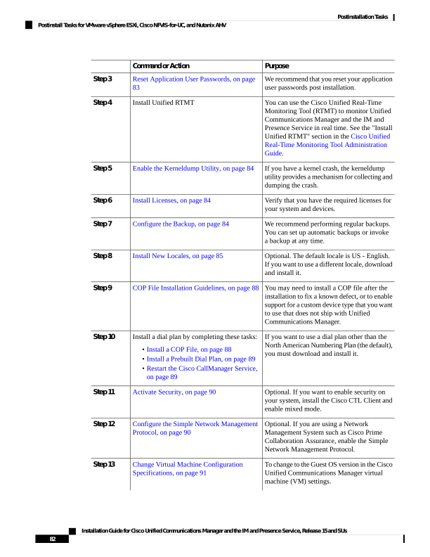
Page 89
Purpose
Command or Action
Note
This step is not applicable for Cisco
NFVIS-for-UC and Nutanix AHV.
This configuration is necessary if your network
topology has a public IP address configured
Ensure that you configure the Trusted List of
Hosts in HTTP Referer/Host Header and
Step 14
for external interfaces along with private IP
add the public IP address or DNS alias in the
address for the individual nodes in the cluster.
Cisco Unified CM Administration Enterprise
Parameters page.
Unified CM will now validate the IP address
or hostname present in the Host header with
the servers configured in the Unified CM
cluster first before allowing access to Unified
CM. You must also configure the DNS alias
used to access the Unified CM under the
Trusted List of Hosts configuration. For
example, if your server is cm1.example.local,
and you use phone.example.local to access the
server, you must add phone.example.local to
the Trusted List of Hosts configuration.
From the private network using a private IP
address, navigate to the Cisco Unified CM
Administration user interface and select
System > Enterprise Parameters to configure
the external IP addresses or DNS alias used.
You must restart the Cisco Tomcat service
after performing this activity for all the web
pages to load correctly.
Reset Application User Passwords
The install process sets all Application User passwords to the same default Application User password that
you entered during installation. We recommend that you reset all these passwords post installation.
Procedure
Step 1
From Cisco Unified CM Administration, choose User Management > Application User.
Step 2
Click Find.
Step 3
Click an application user.
The details of the application user appear in the Application User Configuration window.
Step 4
Enter the new password in both the Password and Confirm Password fields.
Step 5
Click Save.
Step 6
Repeat this procedure for each application user.
Installation Guide for Cisco Unified Communications Manager and the IM and Presence Service, Release 15 and SUs
83
Postinstallation Tasks
Reset Application User Passwords
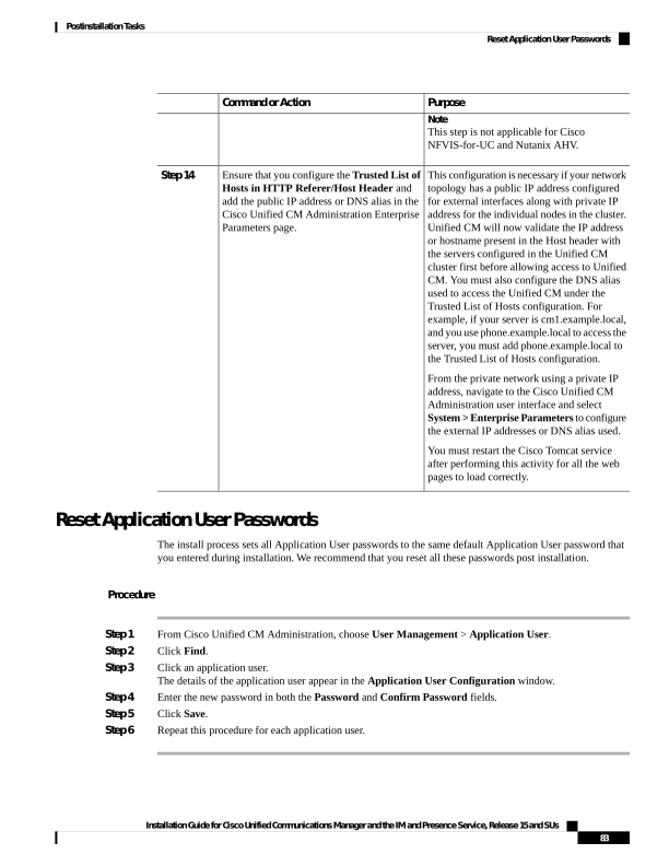
Page 90
Enable the Kerneldump Utility
Use this procedure to enable the kerneldump utility. In the event of a kernel crash, the utility provides a
mechanism for collecting and dumping the crash. You can configure the utility to dump the core to either the
local server, or to an external server.
Procedure
Step 1
Log in to the Command Line Interface.
Step 2
Complete either of the following:
• To dump kernel crashes on the local server, run the utils os kerneldump enable CLI command.
• To dump kernel crashes to an external server, run the utils os kerneldump ssh enable <ip_address>
CLI command with the IP address of the external server.
Step 3
Reboot the server.
Install Licenses
Make sure that you acquire the necessary licenses.
Unified Communications Manager Requirements
Use Cisco Smart Software Manager or Cisco Smart Software Manager satellite to manage licenses for Unified
Communications Manager. For details on how to acquire licenses, see the "Smart Software Licensing" chapter
of the System Configuration Guide for Cisco Unified Communications Manager.
IM and Presence Service Requirements
The IM and Presence Service does not require a server license or software version license.
Configure the Backup
We recommend performing regular backups. You can use the Disaster Recovery System (DRS) to do a full
data backup for all servers in a cluster. You can set up automatic backups or invoke a backup at any time.
You can initiate a manual backup or configure a backup schedule. For more details, see the "Backup the
System" chapter of the Administration Guide for Cisco Unified Communications Manager.
Locale Installation
You can configure Unified Communications Manager and IM and Presence Service to support multiple
languages. There is no limit to the number of supported languages you can install.
Cisco provides locale-specific versions of the Unified Communications Manager Locale Installer and the IM
and Presence Service Locale Installer on www.cisco.com. Installed by the system administrator, the locale
installer allows the user to view/receive the chosen translated text or tones, if applicable, when a user works
with supported interfaces.
Installation Guide for Cisco Unified Communications Manager and the IM and Presence Service, Release 15 and SUs
84
Postinstallation Tasks
Enable the Kerneldump Utility
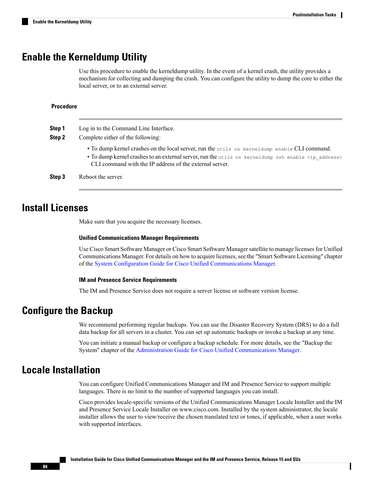
Page 91
For upgrades of Unified Communications Manager or the IM & Presence Service, you must install locales
after you have completed all your upgrades and migrations. For upgrades, you must reinstall any locales that
you are using, except for US-English, which is installed by default. Install the latest version of the locales that
match the major.minor version number of your Unified Communications Manager node or IM and Presence
Service node.
Install locales after you have installed Unified Communications Manager on every node in the cluster and
have set up the database. If you want to install specific locales on IM and Presence Service nodes, you must
first install the Unified Communications Manager locale file for the same country on the Unified
Communications Manager cluster.
Use the information in the following sections to install locales on Unified Communications Manager nodes
and on IM and Presence Service nodes after you complete the software upgrade.
User Locales
User locale files contain language information for a specific language and country. They provide translated
text and voice prompts, if available, for phone displays, user applications, and user web pages in the locale
that the user chooses. These files use the following naming convention:
• cm-locale-language-country-version.cop (Unified Communications Manager)
• ps- locale-language_country-version.cop (IM and Presence Service)
Network Locales
Network locale files provide country-specific files for various network items, including phone tones,
annunciators, and gateway tones. The combined network locale file uses the following naming convention:
• cm-locale-combinednetworklocale-version.cop (Unified Communications Manager)
Cisco may combine multiple network locales in a single locale installer.
You can install locale files from either a local or a remote source by using the same process for installing
software upgrades. You can install more than one locale file on each node in the cluster. Changes do not take
effect until you reboot every node in the cluster. We strongly recommend that you do not reboot the nodes
until you have installed all locales on all nodes in the cluster. Minimize call-processing interruptions by
rebooting the nodes after regular business hours.
Install New Locales
Use this procedure to install a new locale on Unified Communications Manager or IM and Presence Service.
If you are installing a locale for both products, install the locale on all cluster nodes in the following order:
1.
Unified Communications Manager publisher node
2.
Unified Communications Manager subscriber nodes
3.
IM and Presence database publisher node
4.
IM and Presence subscriber nodes
Before you begin
Make sure that you have completed your installation or upgrade of Unified Communications Manager or IM
and Presence Service on all cluster nodes before you attempt to install a new locale.
Installation Guide for Cisco Unified Communications Manager and the IM and Presence Service, Release 15 and SUs
85
Postinstallation Tasks
Install New Locales
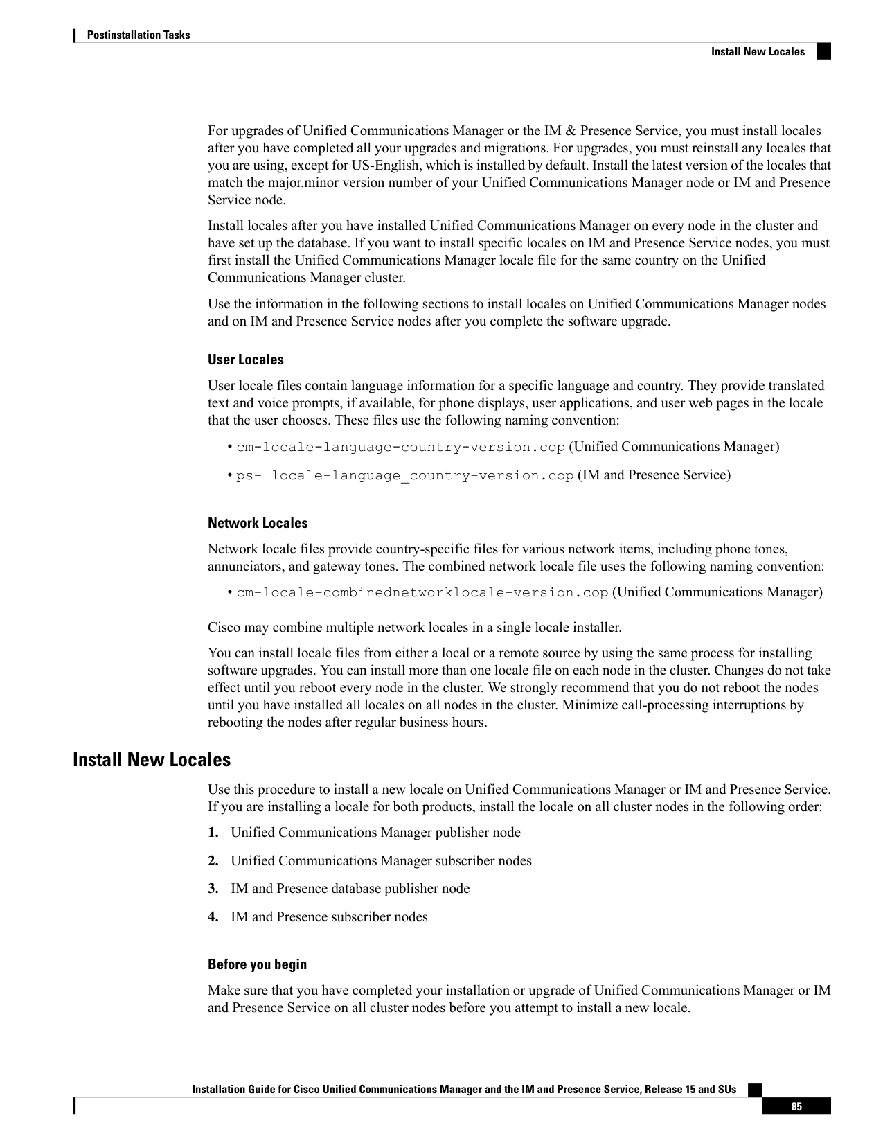
Page 92
Procedure
Step 1
Find the locale installer for your release on cisco.com:
• For Unified Communications Manager, go to https://software.cisco.com/download/
navigator.html?mdfid=268439621&i=rm
• For IM and Presence Service, go to https://software.cisco.com/download/
navigator.html?mdfid=280448682&i=rm
Step 2
Download your release's locale installer to a server that supports SFTP.
Step 3
Log in to Cisco Unified OS Administration using the administrator account.
Step 4
Choose Software Upgrades > Install/Upgrade.
Step 5
Complete the following fields in the Software Installation/Upgrade window:
• For the Source, choose Remote file System.
• From the Directory, enter the path to the directory where you saved the locale installer.
• From the Server field, enter the server name for the remote file system.
• Enter the credentials for the remote file system.
• From the Transfer Protocol drop-down list, choose SFTP. You must use SFTP for the transfer protocol.
Step 6
Click Next.
Step 7
Download and install the locale on the server.
Step 8
Restart the server. The updates take effect after the server restarts.
Step 9
Repeat this procedure on all Unified Communications Manager and IM and Presence Service cluster nodes
in the prescribed order.
Do not reset user locales for your end users until the new locale is installed on all cluster nodes. If you are
installing the locale for both Unified Communications Manager and IM and Presence Service, you must install
the locale for both products before you reset user locales. If you run into any issues, such as could occur if an
end user resets a phone language before the locale installation is complete for IM and Presence Service, have
your users reset their phone language in the Self-Care Portal to English. After the locale installation is complete,
users can reset their phone language, or you use Bulk Administration to synchronize locales to the appropriate
language by bulk.
Note
What to do next
After the locale installation is complete for all cluster nodes, your end users can begin using the new user
locale.
Error Messages
See the following table for a description of the messages that can occur during Locale Installer activation. If
an error occurs, you can view the messages in the installation log.
Installation Guide for Cisco Unified Communications Manager and the IM and Presence Service, Release 15 and SUs
86
Postinstallation Tasks
Error Messages

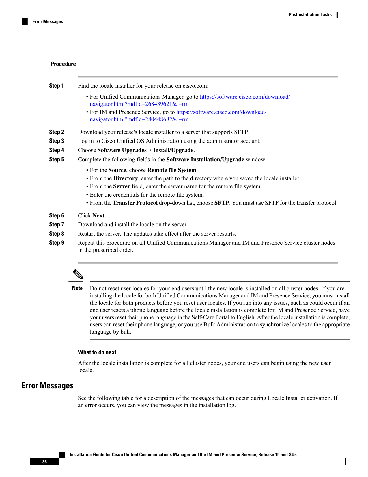
Page 93
Table 7: Locale Installer Error Messages and Descriptions
Description
Message
This error occurs when the system cannot
locate the CSV file, which contains user
locale information to add to the database.
This indicates an error with the build
process.
[LOCALE] File not found:
<language>_<country>_user_locale.csv, the user locale has not
been added to the database.
This error occurs when the system cannot
locate the CSV file, which contains
network locale information to add to the
database. This indicates an error with the
build process.
[LOCALE] File not found: <country>_network_locale.csv, the
network locale has not been added to the database.
This error occurs because a Unified
Communications Manager application
called installdb must be present; it reads
information that is contained in a CSV
file and applies it correctly to the Unified
Communications Manager database. If
this application is not found, it either was
not installed with Unified
Communications Manager (very unlikely),
has been deleted (more likely), or the node
does not have Unified Communications
Manager installed (most likely).
Installation of the locale terminates
because locales do not work without the
correct records that are held in the
database.
[LOCALE] Communications Manager CSV file installer installdb
is not present or not executable.
These errors could occur when the system
fails to create a checksum file; causes can
include an absent Java executable,
/usr/local/thirdparty/java/j2sdk/
jre/bin/java, an absent or damaged
Java archive file,
/usr/local/cm/jar/cmutil.jar,
or an absent or damaged Java class,
com.cisco.ccm.util.Zipper. Even if these
errors occur, the locale will continue to
work correctly, with the exception of
Unified Communications Manager
Assistant, which cannot detect a change
in localized Unified Communications
Manager Assistant files.
[LOCALE] Could not create /usr/local/cm/application_locale
/cmservices/ipma/com/cisco/ipma
/client/locales/maDialogs_<ll>_<CC>.properties.Checksum.
[LOCALE] Could not create
/usr/local/cm/application_locale/cmservices/ipma/com/cisco/
ipma/client/locales/maMessages_<ll>_<CC>.properties.Checksum.
[LOCALE] Could not create /usr/local/cm/
application_locale/cmservices/ipma/com/cisco/
ipma/client/locales/maGlobalUI_<ll>_<CC>.properties.Checksum.
[LOCALE] Could not create /usr/local/cm/
application_locale/cmservices/ipma/
LocaleMasterVersion.txt.Checksum.
Installation Guide for Cisco Unified Communications Manager and the IM and Presence Service, Release 15 and SUs
87
Postinstallation Tasks
Error Messages
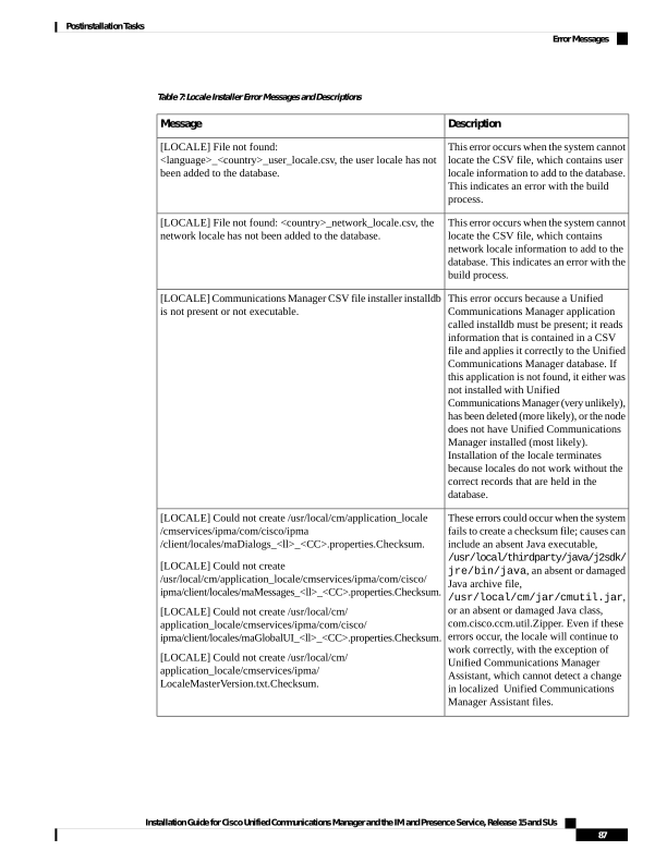
Page 94
Description
Message
This error occurs when the file does not
get found in the correct location, which
is most likely due to an error in the build
process.
[LOCALE] Could not find
/usr/local/cm/application_locale/cmservices/ipma/LocaleMaster
Version.txt in order to update UnifiedCMAssistant locale
information.
This error occurs because of the collective
result of any failure that occurs when a
locale is being installed; it indicates a
terminal condition.
[LOCALE] Addition of <RPM-file-name> to the Unified
Communications Manager database has failed!
COP File Installation Guidelines
Depending on your installation, you may need to install a COP file after the installation to fix a known defect,
or to enable support for a custom device type that you want to use that does not ship with Unified
Communications Manager.
If you need to install a COP file, follow these guidelines:
• Install the appropriate COP file on every node in a cluster. Perform this task before you install new
software on each node in the cluster and after set up the database.
• After you install a COP file, you must restart the node.
• Restart Unified Communications Manager and/or the IM and Presence Service to ensure that configuration
changes that are made during the COP file installation get written into the database.
Install a COP File
If you want to use a prebuilt Dial Plan other than the North American Numbering Plan (the system default),
you must install a COP file with your dial plan.
Procedure
Step 1
Begin this procedure on the Unified Communications Manager publisher node. From Cisco Unified
Communications OS Administration, choose Software Upgrades > Install.
The Software Installation/Upgrade window appears.
Step 2
In the Source field, choose Remote File System.
Step 3
Configure the fields on the Software Installation/Upgrade window. See the Related Topics for more
information about the fields and their configuration options.
Step 4
Click Next.
The window refreshes with a list of available software options and upgrades.
Step 5
From the Options/Upgrades drop-down list, choose the DP COP file and click Next.
The Installation File window opens and downloads the file from the FTP server. The window displays the
progress of the download.
Step 6
When the Checksum window appears, verify the checksum value against the checksum for the file that you
downloaded.
Installation Guide for Cisco Unified Communications Manager and the IM and Presence Service, Release 15 and SUs
88
Postinstallation Tasks
COP File Installation Guidelines
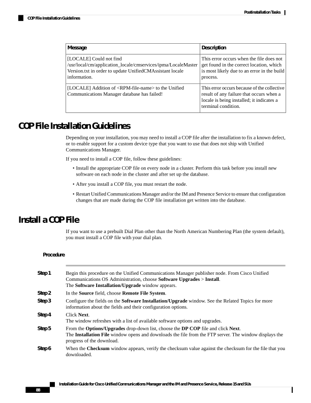
Page 95
Step 7
Click Next to proceed with the software upgrade.
A warning message displays the DP COP file that you selected to install.
Step 8
Click Install.
The Install Status window appears.
Step 9
Click Finish.
Step 10
Repeat this procedure on the Unified Communications Manager subscriber nodes. You must install the COP
file on all the nodes in the cluster.
What to do next
To apply the dial plan to the system, Install a Prebuilt Dial Plan, on page 89.
Install a Prebuilt Dial Plan
Install the national numbering plan on each Unified Communications Manager node in the cluster beginning.
Begin with the Unified Communications Manager publisher node.
Complete this procedure only if you are installing a national numbering plan for countries outside of North
America (the system default).
Note
Before you begin
Install a COP file with your prebuilt dial plan. For details, see Install a COP File, on page 88.
Procedure
Step 1
From Cisco Unified Communications Manager Administration, choose Call Routing > Dial Plan Installer.
Step 2
Enter search criteria and click Find.
Step 3
Choose the dial plan version that you want to install from the Available Version drop-down list.
Step 4
Click Install.
The Status displays that the dial plan has been installed.
Step 5
Repeat this procedure for every subscriber node in the cluster.
What to do next
Restart the Cisco CallManager Service, on page 89
Restart the Cisco CallManager Service
If you have installed a new dial plan, you must restart the Cisco CallManager service.
Installation Guide for Cisco Unified Communications Manager and the IM and Presence Service, Release 15 and SUs
89
Postinstallation Tasks
Install a Prebuilt Dial Plan

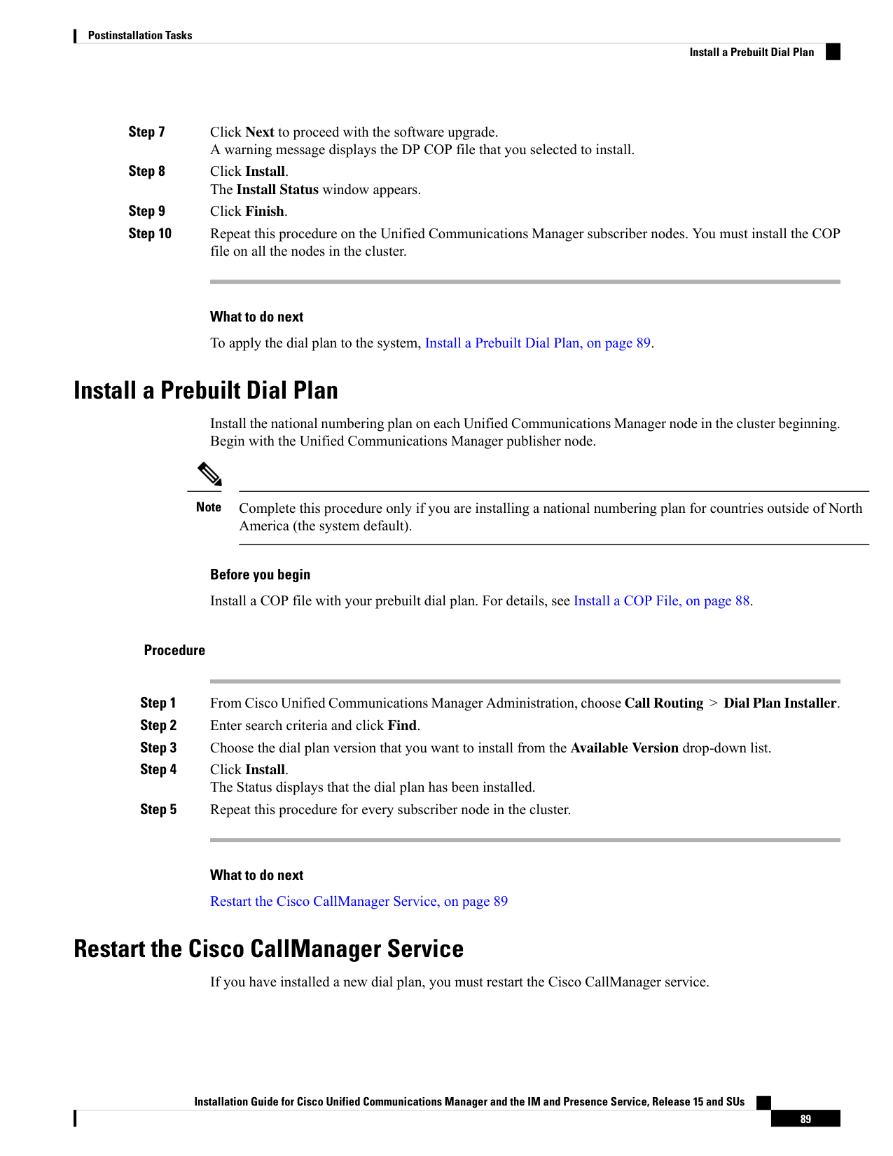
Page 96
Procedure
Step 1
From the Cisco Unified Serviceability interface, choose Tools > Control Center - Feature Services.
Step 2
Choose the Unified Communications Manager server from the Servers drop-down list.
In the CM Services area, Cisco CallManager displays in the Service Name column.
Step 3
Click the radio button that corresponds to the Cisco CallManager service.
Step 4
Click Restart.
The service restarts and displays the message, Service Successfully Restarted.
Activate Security
If you want to enable security on your system, you must install the Cisco CTL Client and enable mixed mode.
You can download the CTL installation file in Cisco Unified CM Administration from the Applications >
Plugins window.
When mixed mode is enabled, the system uses the Certificate Trust List (CTL) file for authentication. The
CTL file contains a server certificate, public key, serial number, signature, issuer name, subject name, server
function, DNS name, and IP address for each server.
For details on how to install the CTL client and enable mixed mode on your system, see the Security Guide
for Cisco Unified Communications Manager.
Configure the Simple Network Management Protocol
If you are using a Network Management System, such as Cisco Prime Collaboration Assurance, enable the
Simple Network Management Protocol.
Before you begin
Your system does not allow more than ten concurrent polling queries. We recommend a maximum of eight
trap destinations; anything higher will affect CPU performance. This requirement applies to all installations
regardless of the OVA template that you use.
Procedure
Step 1
Install and configure the SNMP NMS.
Step 2
In the Control Center - Network Services window, verify that the system started the SNMP services.
Step 3
Unified Communications Manager: In the Service Activation window, activate the Cisco CallManager SNMP
service. Cisco Unity Connection only: The Connection SNMP Agent service automatically activates.
Step 4
If you are using SNMP V1/V2c, configure the community string.
Step 5
If you are using SNMP V3, configure the SNMP user.
Step 6
Configure the notification destination for traps or informs.
Step 7
Configure the system contact and location for the MIB2 system group.
Installation Guide for Cisco Unified Communications Manager and the IM and Presence Service, Release 15 and SUs
90
Postinstallation Tasks
Activate Security
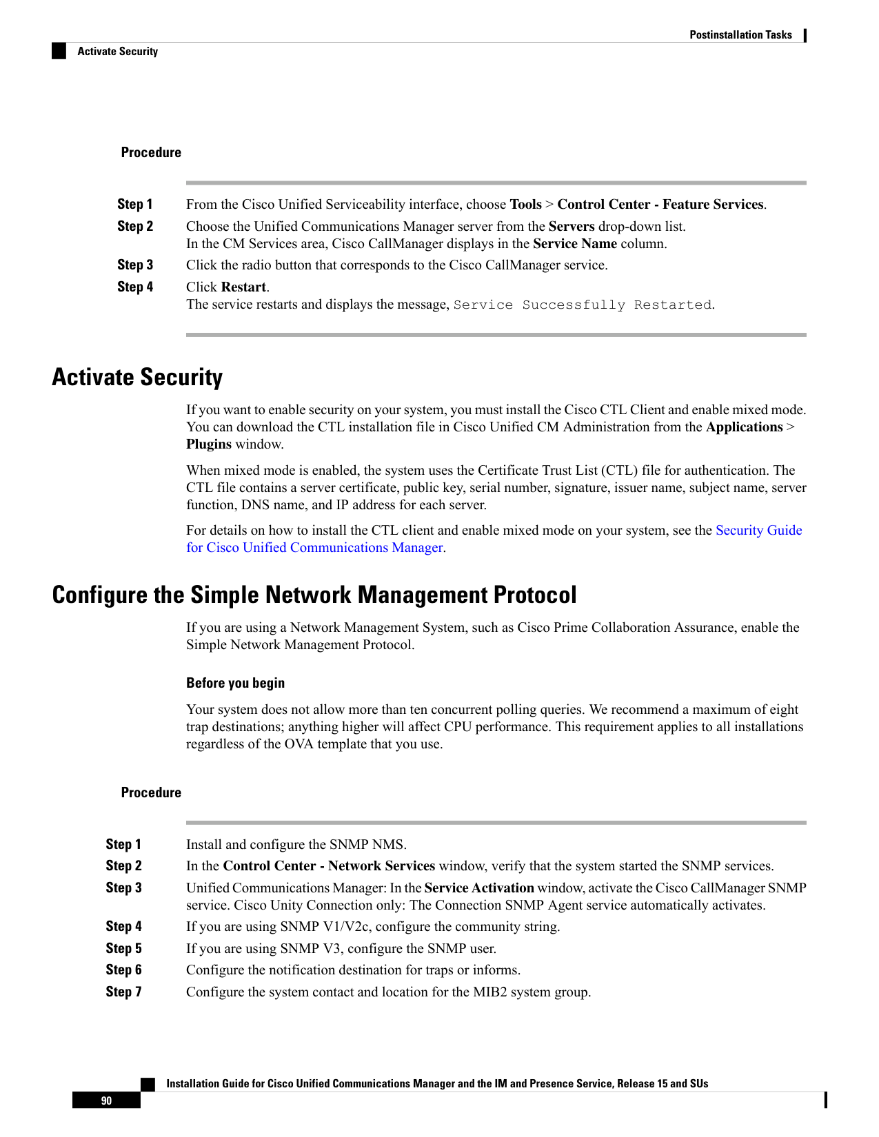
Page 97
Step 8
Configure trap settings for CISCO-SYSLOG-MIB.
Step 9
Unified Communications Manager only: Configure trap settings for CISCO-CCM-MIB.
Step 10
Restart the Primary Agent service.
Step 11
On the NMS, configure the Unified Communications Manager trap parameters.
Change Virtual Machine Configuration Specifications
Use the following procedure to change to the Guest OS version in the Unified Communications Manager
virtual machine (VM) settings.
Procedure
Step 1
Shut down the virtual machine.
Step 2
Change the configuration of the virtual machine as needed through vSphere. You can update the Guest OS
and VM Hardware Compatibly.
a.
Update VM Hardware Compatibly—Left click Virtual Machine. Check for Updates. Click Update
Note
If you are not aware of the host click Check statuts and click Upgrade to match host.
b.
Update Guest OS—Right click the Virtual Machine > Edit Settings > Virtual Machine Option >
General Option > Guest OS Version.
Step 3
Power on the Virtual Machine.
Note
Following warning messages appears in ESXi while opening the Virtual Machine settings while running when
there is a mismatch.
Warning
The configured guest OS (CentOS 4/5 or later (64 bit)) for this virtual machine does not match the guest that
is currently running (CentOS 7 (64 bit)). You should specify the correct guest OS to allow for guest-specific
optimizations.
Postinstall tasks for the IM and Presence Service (VMware
vSphere ESXi, Cisco NFVIS-for-UC, and Nutanix AHV)
If you have installed a new cluster or new node for the IM and Presence Service, complete these tasks after
your installation.
Installation Guide for Cisco Unified Communications Manager and the IM and Presence Service, Release 15 and SUs
91
Postinstallation Tasks
Change Virtual Machine Configuration Specifications
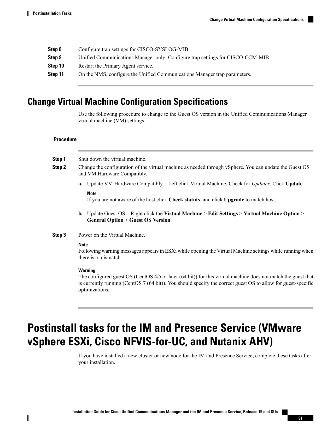
Page 98
Many of these tasks are documented in more detail in the Configuration and Administration of the IM and
Presence Service Guide. Where indicated, see that guide for detail on how to complete these tasks.
Note
Procedure
Purpose
Command or Action
You can download Release Notes from the
below URL. Make sure that you understand
Read the Release Notes and any Readme files
that come with your release.
Step 1
the features for your release and any COP file
requirements.
https://www.cisco.com/c/en/us/support/
unified-communications/
unified-communications-manager-callmanager/
products-release-notes-list.html
You can download software from
https://software.cisco.com/download/
navigator.html?mdfid=280448682&i=rm
Check for software and firmware updates for
IM and Presence Service on Cisco.com.
Step 2
For details, see the Configuration and
Administration of the IM and Presence Service
Guide.
Configure Presence Redundancy Groups.
Step 3
For details, see the Configuration and
Administration of the IM and Presence Service
Guide.
Assign users to servers.
Step 4
Turn on essential IM and Presence Service
services.
Activate services, on page 93
Step 5
For details, see the Configuration and
Administration of the IM and Presence Service
Guide.
(Optional) Change the default domain.
Step 6
For details, see the Configuration and
Administration of the IM and Presence Service
Guide.
(Optional) Change the IM and Presence
Service IM address scheme.
Step 7
For details, see the Configuration and
Administration of the IM and Presence Service
Guide.
(Optional) Change the IM and Presence
Service node name.
Step 8
For details, see the Configuration and
Administration of the IM and Presence Service
Guide.
(Optional) Configure Unified Communications
Manager as a Presence Gateway.
Step 9
For details, see the Configuration and
Administration of the IM and Presence Service
Guide.
(Optional) Configure a SIP Publish trunk on
Unified Communications Manager.
Step 10
Installation Guide for Cisco Unified Communications Manager and the IM and Presence Service, Release 15 and SUs
92
Postinstallation Tasks
Postinstall tasks for the IM and Presence Service (VMware vSphere ESXi, Cisco NFVIS-for-UC, and Nutanix AHV)

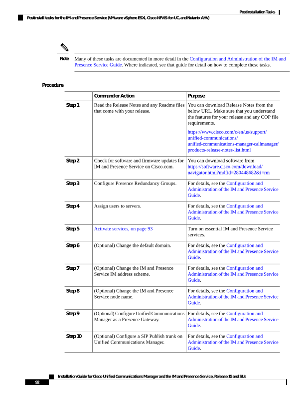
Page 99
Activate services
You must activate the following services:
• Cisco SIP Proxy
• Cisco Presence Engine
• Cisco XCP Connection Manager
• Cisco XCP Authentication Service
To activate the services, select Tools > Service Activation in Cisco Unified Serviceability.
You must complete this task on each server that you install in an IM and Presence cluster.
Note
Where to Go Next
You have now installed your system. You are now ready to proceed with configuring your system, including
tasks such as configuring the dial plan, provisioning users, registering devices, and setting up instant messaging
and presence. See the following guide for details on how to configure your system:
• System Configuration Guide for Cisco Unified Communications Manager
Installation Guide for Cisco Unified Communications Manager and the IM and Presence Service, Release 15 and SUs
93
Postinstallation Tasks
Activate services

Page 100
Installation Guide for Cisco Unified Communications Manager and the IM and Presence Service, Release 15 and SUs
94
Postinstallation Tasks
Where to Go Next

Page 101
C H A P T E R 6
Troubleshooting
• Network Errors During Installation, on page 95
• Failed Installations, on page 96
• Unrecoverable IM and Presence Service Node, on page 96
Network Errors During Installation
During the installation process, the installation program verifies that the server can successfully connect to
the network by using the network configuration that you enter. If it cannot connect, a message displays, and
you get prompted to select one of the following options:
• —RETRY - The installation program tries to validate networking again. If validation fails again, the
error dialog box displays again.
• —REVIEW (Check Install) - This option allows you to review and modify the networking configuration.
When detected, the installation program returns to the network configuration windows.
• Networking gets validated after you complete each networking window, so the message might display
multiple times.
• —HALT - The installation halts. You should use the Recovery CD to recover the logs to access the
diagnostic information. For more details, see Obtain and Run Recovery Software on the CUCM VM.
We no longer support the collection of logs by dumping them to serial port due
to CentOS limitations.
Note
• —IGNORE - The installation continues. The networking error gets logged. Sometimes, the installation
program validates networking multiple times, so this error dialog box might display multiple times. If
you choose to ignore network errors, the installation may fail.
Steps to Recover Logs using Recovery CD
You should use the Recovery CD to recover the logs to access the diagnostic information. Follow the steps
mentioned:
1.
Insert the recovery CD.
Installation Guide for Cisco Unified Communications Manager and the IM and Presence Service, Release 15 and SUs
95


Page 102
Reboot the system.
3.
Once the recovery CD menu comes up, press Alt + F2 to get to the command prompt.
4.
Find the largest partition by performing a "df -h". (/mnt/part6).
5.
Locate the install logs at: /mnt/part6/log/install/ directory.
6.
Collect the logs.
Failed Installations
If your installation fails, check the configuration and confirm the following:
• Parse the passwords from the platformconfig.xml file to verify security password.
• Complete a packet capture from Unified Communications Manager to confirm that the IM and Presence
Service IP address is reaching Unified Communications Manager during the install.
• Verify that NTP is synchronized on Unified Communications Manager.
• If you get a message that install has failed and you want to recover the logs to access the diagnostic
information, see Obtain and Run Recovery Software on the CUCM VM.
We no longer support the collection of logs by dumping them to serial port due
to CentOS limitations.
Note
• Confirm that the version of the IM and Presence Service and Unified Communications Manager are
compatible.
• If you are installing a subscriber, verify that the subscriber node is the same version as the publisher
node. The subscriber OVA should be the same OVA that is used for the publisher.
Unrecoverable IM and Presence Service Node
If a node is in a state that cannot be recovered you must reinstall the node.
If you reinstall a node in an intercluster deployment, you must delete and re-add the intercluster peer connections
between the reinstalled node and the other nodes in the cluster.
Note
IM and Presence Service Database Publisher Node
Complete the following high-level procedure to reinstall an IM and Presence Service database publisher node.
Installation Guide for Cisco Unified Communications Manager and the IM and Presence Service, Release 15 and SUs
96
Troubleshooting
Failed Installations

Page 103
If you do not complete all of these steps in the order shown, recovery of the IM and Presence Service database
publisher node will fail.
Note
1.
Power down all the IM and Presence Service subscriber nodes.
2.
Delete the subscriber nodes as follows:
a.
Unassign all users that are assigned to each of the IM and Presence Service subscriber nodes. (Select
Cisco Unified CM Administration > User Management > Assign Presence Users).
b.
Remove the subscriber nodes from their presence redundancy groups. (Select Cisco Unified CM
Administration > System > Presence Redundancy Groups).
c.
Delete the subscriber nodes from the Unified Communications Manager server list. (Select Cisco
Unified CM Administration > System > Server).
3.
Power down the IM and Presence Service database publisher node.
4.
Delete the IM and Presence Service database publisher node as follows:
a.
Unassign the users that are assigned to the IM and Presence Service database publisher node. (Select
Cisco Unified CM Administration > User Management > Assign Presence Users).
b.
Remove the node from the presence redundancy group. (Select Cisco Unified CM Administration >
System > Presence Redundancy Groups).
c.
Delete the IM and Presence Service database publisher node from the Unified Communications
Manager server list. (Select Cisco Unified CM Administration > System > Server).
5.
Readd the IM and Presence Service database publisher node to the Unified Communications Manager
server list.
6.
Perform a fresh install of the IM and Presence Service database publisher node.
7.
Readd the IM and Presence Service subscriber nodes to the Unified Communications Manager server list.
8.
Perform a fresh install of each subscriber node.
IM and Presence Service Subscriber Node
Complete the following high-level procedure to reinstall an IM and Presence Service subscriber node.
If you do not complete all of these steps in the order shown, recovery of the IM and Presence Service subscriber
node will fail.
Note
1.
Power down the IM and Presence Service node.
2.
Delete the subscriber node as follows:
a.
Unassign the users that are assigned to the node. (Select Cisco Unified CM Administration > User
Management > Assign Presence Users).
Installation Guide for Cisco Unified Communications Manager and the IM and Presence Service, Release 15 and SUs
97
Troubleshooting
Unrecoverable IM and Presence Service Node


Page 104
b.
Remove the node from the presence redundancy group. (Select Cisco Unified CM Administration >
System > Presence Redundancy Groups).
c.
Delete the node from the Unified Communications Manager server list. (Select Cisco Unified CM
Administration > System > Server)
3.
Readd the IM and Presence Service node to the Unified Communications Manager server list.
4.
Perform a fresh install of the node.
Installation Guide for Cisco Unified Communications Manager and the IM and Presence Service, Release 15 and SUs
98
Troubleshooting
Unrecoverable IM and Presence Service Node