Document Metadata
Format: PDF 1.4
Title: Call Reporting and Billing Administration Guide for Cisco Unified Communications Manager, Release 15 and SUs
Author: Jayasree N
Creator: DITA Open Toolkit
Producer: XEP 4.30.961; modified using iText 2.1.7 by 1T3XT
Creation Date: D:20260409035928Z
Mod Date: D:20260408210327-07'00'
Page 1
Call Reporting and Billing Administration Guide for Cisco Unified
Communications Manager, Release 15 and SUs
First Published: 2023-12-18
Last Modified: 2026-04-09
Americas Headquarters
Cisco Systems, Inc.
170 West Tasman Drive
San Jose, CA 95134-1706
USA
http://www.cisco.com
Tel: 408 526-4000
800 553-NETS (6387)
Fax: 408 527-0883

Page 2
THE SPECIFICATIONS AND INFORMATION REGARDING THE PRODUCTS IN THIS MANUAL ARE SUBJECT TO CHANGE WITHOUT NOTICE. ALL STATEMENTS,
INFORMATION, AND RECOMMENDATIONS IN THIS MANUAL ARE BELIEVED TO BE ACCURATE BUT ARE PRESENTED WITHOUT WARRANTY OF ANY KIND,
EXPRESS OR IMPLIED. USERS MUST TAKE FULL RESPONSIBILITY FOR THEIR APPLICATION OF ANY PRODUCTS.
THE SOFTWARE LICENSE AND LIMITED WARRANTY FOR THE ACCOMPANYING PRODUCT ARE SET FORTH IN THE INFORMATION PACKET THAT SHIPPED WITH
THE PRODUCT AND ARE INCORPORATED HEREIN BY THIS REFERENCE. IF YOU ARE UNABLE TO LOCATE THE SOFTWARE LICENSE OR LIMITED WARRANTY,
CONTACT YOUR CISCO REPRESENTATIVE FOR A COPY.
The Cisco implementation of TCP header compression is an adaptation of a program developed by the University of California, Berkeley (UCB) as part of UCB's public domain version of
the UNIX operating system. All rights reserved. Copyright © 1981, Regents of the University of California.
NOTWITHSTANDING ANY OTHER WARRANTY HEREIN, ALL DOCUMENT FILES AND SOFTWARE OF THESE SUPPLIERS ARE PROVIDED “AS IS" WITH ALL FAULTS.
CISCO AND THE ABOVE-NAMED SUPPLIERS DISCLAIM ALL WARRANTIES, EXPRESSED OR IMPLIED, INCLUDING, WITHOUT LIMITATION, THOSE OF
MERCHANTABILITY, FITNESS FOR A PARTICULAR PURPOSE AND NONINFRINGEMENT OR ARISING FROM A COURSE OF DEALING, USAGE, OR TRADE PRACTICE.
IN NO EVENT SHALL CISCO OR ITS SUPPLIERS BE LIABLE FOR ANY INDIRECT, SPECIAL, CONSEQUENTIAL, OR INCIDENTAL DAMAGES, INCLUDING, WITHOUT
LIMITATION, LOST PROFITS OR LOSS OR DAMAGE TO DATA ARISING OUT OF THE USE OR INABILITY TO USE THIS MANUAL, EVEN IF CISCO OR ITS SUPPLIERS
HAVE BEEN ADVISED OF THE POSSIBILITY OF SUCH DAMAGES.
Any Internet Protocol (IP) addresses and phone numbers used in this document are not intended to be actual addresses and phone numbers. Any examples, command display output, network
topology diagrams, and other figures included in the document are shown for illustrative purposes only. Any use of actual IP addresses or phone numbers in illustrative content is unintentional
and coincidental.
All printed copies and duplicate soft copies of this document are considered uncontrolled. See the current online version for the latest version.
Cisco has more than 200 offices worldwide. Addresses and phone numbers are listed on the Cisco website at www.cisco.com/go/offices.
Cisco and the Cisco logo are trademarks or registered trademarks of Cisco and/or its affiliates in the U.S. and other countries. To view a list of Cisco trademarks, go to this URL:
https://www.cisco.com/c/en/us/about/legal/trademarks.html. Third-party trademarks mentioned are the property of their respective owners. The use of the word partner does not imply a
partnership relationship between Cisco and any other company. (1721R)
© 2023–2026 Cisco Systems, Inc. All rights reserved.
Page 3
C O N T E N T S
New and Changed Information
1
C H A P T E R 1
New and Changed Information
1
CDR Analysis and Reporting
3
P A R T I
Overview
5
C H A P T E R 2
CDR Analysis and Reporting Overview
5
CDR Management
8
Roles
11
Reports
11
Report Information
11
Generated Report Schedule
12
Audit Logging
12
Log-On Message
13
Internationalization
13
Online Help
14
Backup Database
14
CPU Utilization
15
Initial Setup
17
C H A P T E R 3
CDR Analysis and Reporting Configuration Overview
17
CDR Analysis and Reporting Initial Setup
18
Activate CAR
20
Configure CDR Repository Manager File Preservation Settings
21
Set Up Application Billing Servers
22
Billing Server Authentication Issue
23
Call Reporting and Billing Administration Guide for Cisco Unified Communications Manager, Release 15 and SUs
iii

Page 4
Configure CDR Enterprise Parameters
23
Configure CDR Service Parameters
24
Generate CAR Users
25
CAR System Settings
26
Log On to CAR
27
Log Out of CAR
30
CAR System Parameters
30
Set Up Mail Server Parameters
31
Set Up Dial Plan
31
Restore Default Values
32
Set Up Gateway
34
Set Up Trunk
35
Set Up System Preferences
36
Set Up CDR Load Schedule
36
Schedule Daily Reports
39
Schedule Weekly Reports
39
Schedule Monthly Reports
40
Alarms
42
CAR System Database
43
Purge CAR Database
43
Set Up Automatic Database Purge
45
CAR System Event Log
46
Generate Event Log
46
Output of Event Log Report
49
CAR Reports Configuration
50
CAR Rating Engine
51
Set Base Rate
51
Factor Time of Day
52
Factor Voice Quality
53
Define QoS Values
54
Automatic Generation of CAR Reports and Alerts
55
Enable Automatic Generation Reports
57
Enable Email Alerts
58
CAR Reports Notification Limits
59
Call Reporting and Billing Administration Guide for Cisco Unified Communications Manager, Release 15 and SUs
iv
Contents
Page 5
Set Notification Limits
59
User Reports
61
C H A P T E R 4
User Reports Overview
61
User Reports Description
61
Mail Reports
63
View CSV Reports
64
Search Users
64
Bills User Reports
65
Bills Reports
65
Generate Individual Bills Reports
66
Generate Department Bills Reports
67
Top N User Reports
68
Top N Reports
69
Generate Top N by Charge Reports
69
Generate Top N by Duration Reports
71
Generate Top N by Number of Calls Reports
73
Assistant User Reports
74
Assistant Usage Reports
74
Generate Manager Call Usage Assistant Reports
75
Generate Assistant Call Usage Assistant Reports
76
IP Phone Service User Reports
76
Generate IP Phone Services Reports
77
Review User Reports Results
77
Bill Summary Report Results
78
Bill Detail Report Results
80
Top N by Charge or Duration Report Results
82
Top N by Number of Calls Report Results
84
Call Usage for Assistant Detail Report Results
85
Call Usage for Assistant Summary Report Results
87
Call Usage for Manager Detail Report Results
88
Call Usage for Manager Summary Report Results
89
IP Phone Services Report Results
90
Call Reporting and Billing Administration Guide for Cisco Unified Communications Manager, Release 15 and SUs
v
Contents
Page 6
System Reports
93
C H A P T E R 5
CAR System Reports
93
System Reports Summary Description
93
User Search
95
QoS System Reports
96
Generate QoS Detail Reports
97
Generate QoS Summary Reports
99
Generate QoS by Gateway Reports
100
Generate QoS by Call Types Reports
102
Traffic System Reports
104
Generate Traffic Summary Reports
105
Generate Traffic Summary by Phone Number Reports
107
FAC/CMC System Reports
110
Generate Client Matter Code Reports
110
Generate Authorization Code Name Reports
111
Generate Authorization Level Reports
112
Malicious Call Details System Reports
112
Generate Malicious Call Details Reports
113
Precedence Call Summary System Reports
113
Generate Precedence Call Summary Reports
113
System Reports
115
Generate System Reports
115
CDR Error System Reports
116
Generate CDR Error Reports
117
System Reports Results
119
QoS Detail Report Results
119
QoS Summary Report Results
121
QoS by Gateways Report Results
122
QoS by Call Types Report Results
123
Traffic Summary Report Results
125
Authorization Code Name Call Details Report Results
128
Authorization Level Call Details Report Results
129
Client Matter Code Details Report Results
130
Call Reporting and Billing Administration Guide for Cisco Unified Communications Manager, Release 15 and SUs
vi
Contents
Page 7
Malicious Call Details Report Results
131
Precedence Call Summary Report Results
132
System Report Results
133
CDR Error Report Results
135
Device Reports
137
C H A P T E R 6
CAR Device Reports
137
Device Reports Summary Descriptions
137
Gateway Device Reports
139
Generate Gateway Detail Reports
139
Generate Gateway Summary Reports
142
Generate Gateway Utilization Reports
143
Route Pattern and Hunt Pilot Device Reports
145
Generate Route and Line Group Utilization Reports
146
Generate Route and Hunt List Utilization Reports
147
Generate Route Pattern and Hunt Pilot Utilization Reports
149
Generate Hunt Pilot Summary Report
150
Generate Hunt Pilot Detail Report
151
Conference Bridge Device Reports
152
Generate Conference Call Details
152
Generate Conference Bridge Utilization Reports
153
Voice Messaging Utilization Device Reports
154
Generate Voice Messaging Utilization Reports
155
Trunk Device Reports
157
Generate Trunk Utilization Reports
157
CAR Device Reports Results
159
Gateway Detail Report Results
159
Gateway Summary Report Results
160
Gateway and Route Utilization Report Results
162
Hunt Pilot Summary Report Results
166
Hunt Pilot Detail Report Results
168
Conference Call Detail Report Results
170
Conference Bridge Utilization Report Results
171
Voice Messaging Utilization Report Results
172
Call Reporting and Billing Administration Guide for Cisco Unified Communications Manager, Release 15 and SUs
vii
Contents

Page 8
Trunk Utilization Report Results
174
Export CDRs and CMRs
179
C H A P T E R 7
CDR and CMR Records
179
Export CDR and CMR Records
179
View CDR and CMR Records Results
179
CDR Data
180
CDR Search
182
Generate CDR Search by User
183
Generate CDR Search by Gateway
185
Generate CDR Search by Cause for Call Termination
186
View Call Termination Details
192
Generate CDR Search by Call Precedence
192
Generate CDR Search for Malicious Calls
194
Generate CDR Search for Call Types
195
CDR Search Results
196
Media Information
197
CDR and CMR Dump Tables
198
CDR Records
201
P A R T I I
Call Details Records Overview
203
C H A P T E R 8
CDR Management
203
CDR Agent
204
CDR Repository Manager
204
CDR onDemand Service
205
CDR Database Backup and Recovery
205
Record Processing
205
Call Information Record Types
207
Global Call Identifier
207
Number Translations
208
Partitions and Numbers
208
Timestamps
210
Call Clearing Causes
210
Call Reporting and Billing Administration Guide for Cisco Unified Communications Manager, Release 15 and SUs
viii
Contents
Page 9
Convert Signed Decimal Value to IP Address
211
CDR Field Descriptions
213
C H A P T E R 9
CDR Field Descriptions
213
Routing Reason Values for External Call Control
236
Cisco Call Detail Records Codes
237
Codec Types
237
Call Termination Cause Codes
240
Redirect Reason Codes
246
OnBehalfof Codes
249
CDR Examples
251
C H A P T E R 1 0
AAC Calls
252
Abandoned Calls
254
Ad Hoc Conference Linking
256
Conference Linking Using Join
256
Conference Linking Using Transfer or Direct Transfer
258
Linked Conference Party Removal
260
Linked Conference Party (Controller) Removal
262
Linked Conference Removal
264
Agent Greeting Calls
266
Barge
267
Call Monitoring
269
Call Park
271
Call Park Pickup
271
Call Park Reversion
272
Call Pickup
273
Pickup
273
Auto Pickup
274
Call Recording
275
Call Secured Status
277
Calling Party Normalization
278
Calls with Busy or Bad Destinations
279
cBarge
280
Call Reporting and Billing Administration Guide for Cisco Unified Communications Manager, Release 15 and SUs
ix
Contents
Page 10
Client Matter Code (CMC)
282
Conference Calls
283
Operational Factors
286
Conference Now Calls
287
Conference Drop Any Party
289
Original Calling Party on Transfer
290
DTMF Method
290
End-to-End Call Trace
291
Forced Authorization Code (FAC)
295
Forwarded or Redirected Calls
297
Hunt List Support
299
H.239
302
iLBC Calls
303
Intercompany Media Engine
306
Immediate Divert (to Voice-Messaging System)
310
IMS Application Server
312
Intercom Calls
313
IPv6 Calls
314
Legacy Call Pickup
319
Local Route Groups and Called Party Transformation
320
Logical Partitioning Calls
321
Malicious Calls
323
Meet-Me Conferences
323
Mobility
324
Native Call Queuing
337
Normal Calls (Cisco Unified IP Phone to Cisco Unified IP Phone)
338
Original Calling Party on Transfer
339
Personal Assistant Calls
340
Personal Assistant Direct Call
340
Personal Assistant Interceptor Going to Media Port and Transferring Call
340
Personal Assistant Interceptor Going Directly to Destination
341
Example Personal Assistant Interceptor Going Directly to Destination with No Rules CDR
341
Example Personal Assistant Going Directly to Destination with Rule to Forward Calls to Different
Destination CDR
341
Call Reporting and Billing Administration Guide for Cisco Unified Communications Manager, Release 15 and SUs
x
Contents
Page 11
Personal Assistant Interceptor Going to Multiple Destinations
342
Personal Assistant Conferencing
345
Precedence Calls (MLPP)
346
Redirection (3xx) Calls
347
Redirecting Number Transformation
348
Refer Calls
349
Replaces Calls
349
RSVP
351
Secure Conference Meet-Me
352
Short Calls
353
SIP Call with URL in CallingPartyNumber Field
353
Successful on Net Calls
354
Transferred Calls
354
Video Calls
357
Video Conference Calls
358
CMR Records
363
P A R T I I I
Call Management Records
365
C H A P T E R 1 1
Call Management Records Overview
365
CMR Processing
365
CMRs for SIP Trunks
366
CMRs for Headsets
368
CMRs for Headsets
369
Set Up CMRs
369
CPU Utilization
370
CMR Field Descriptions
371
C H A P T E R 1 2
CMR Field Descriptions
371
K-Factor Data
380
CMR Examples
383
C H A P T E R 1 3
CMR Examples
383
Call Reporting and Billing Administration Guide for Cisco Unified Communications Manager, Release 15 and SUs
xi
Contents
Page 12
Call Reporting and Billing Administration Guide for Cisco Unified Communications Manager, Release 15 and SUs
xii
Contents

Page 13
C H A P T E R 1
New and Changed Information
• New and Changed Information, on page 1
New and Changed Information
The following table provides an overview of the significant changes to the features in this guide up to this
current release. The table does not provide an exhaustive list of all changes made to the guide or of the new
features up to this release.
Table 1: New Features and Changed Behavior in Unified Communications Manager
See
Description
—
No new technical features were
introduced for this release.
December 18, 2023
Call Reporting and Billing Administration Guide for Cisco Unified Communications Manager, Release 15 and SUs
1

Page 14
Call Reporting and Billing Administration Guide for Cisco Unified Communications Manager, Release 15 and SUs
2
New and Changed Information
New and Changed Information

Page 15
P A R T I
CDR Analysis and Reporting
• Overview, on page 5
• Initial Setup, on page 17
• User Reports, on page 61
• System Reports, on page 93
• Device Reports, on page 137
• Export CDRs and CMRs, on page 179

Page 16
Page 17
C H A P T E R 2
Overview
The Cisco CDR Analysis and Reporting (CAR) tool generates reports for quality of service, traffic, user call
volume, billing, and gateways. CAR uses data from Call Detail Records (CDRs), Call Management Records
(CMRs), and the Unified Communications Manager database in order to generate reports. The CAR interface
can be accessed under the Tools menu of Cisco Unified Serviceability.
CAR is not intended to replace call accounting and billing solutions that third-party companies provide. You
can find the companies that provide these solutions and that are members of the Cisco Technology Developer
Program by searching the home page of the Cisco Developer Community.
CAR does not handle iDivert calls (a feature that diverts calls to a voice-messaging system) and treats them
as normal calls. The part of the call after the iDivert feature gets activated may not get charged to the correct
party.
Note
• CDR Analysis and Reporting Overview, on page 5
CDR Analysis and Reporting Overview
As its primary function, CAR generates reports about the users of Unified Communications Manager and
generates reports on the system status about call processing. CAR also performs CAR database management
activities. You can perform these tasks in one of the following ways:
• Automatically configure the required tasks to take place.
• Manually perform the tasks by using the web interface.
You access CAR from the Tools menu of Cisco Unified Serviceability after you activate the appropriate
services as described in the Activate CAR, on page 20.
All CAR reports use CDR data. CAR processes the CDRs from flat files that the CDR Repository service
places in the CDR repository folder structure. CAR processes CDRs at a scheduled time and frequency. By
default, CDR data loads continuously 24 hours per day and seven days per week; however, you can set the
loading time, interval, and duration as needed. In addition, the default setting loads only CDR records. CMR
records do not get loaded by default.
Call Reporting and Billing Administration Guide for Cisco Unified Communications Manager, Release 15 and SUs
5


Page 18
An option allows you to uncheck the “Load CDR Only” check box in the CAR System Scheduler window to
allow CMR records to load. See Set Up CDR Load Schedule, on page 36 for additional information.
Note
CAR retrieves information that requires for various reports from CDRs, CMRs, and the Unified Communications
Manager database.
Scheduling Reports
After CAR is activated on your system, you can schedule CAR reports to generate automatically at a regular
time. Each report that can be scheduled has its own report generation interval. You can make the report
generation interval be daily, weekly, or monthly. Scheduling Daily reports schedules all the reports that have
report generation intervals of daily. Similarly, scheduling Weekly or Monthly reports would schedule the
reports that have report generation intervals of weekly or monthly. You can also specify the time to keep a
report before it gets automatically deleted.
By default, CAR uses the following report generation and deletion schedule:
• Daily reports run at 1 a.m. every day. These reports get purged after two days.
• Weekly reports run at 4 a.m. every Sunday. These reports get purged after four weeks.
• Monthly bill reports run at 3 a.m. on the first day of every month. These reports get purged after two
months.
• Other monthly reports run at 2 a.m. on the first day of every month. These reports get purged after two
months.
If you upgrade your system to a new version of Unified Communications Manager, you must disable the CAR
reports that generate automatically, so you conserve system resources during the upgrade process.
Note
For a list of reports and the default generation schedule, see the Enable Automatic Generation Reports, on
page 57.
For system monitoring, automatically generate various reports, such as QoS reports, and review them at regular
intervals, perhaps every day if you have a large system, or every week or every two weeks for smaller systems.
QoS reports helping you determine the quality of calls that run on your network and judge whether you need
additional hardware to improve performance. You can use utilization reports for gateways, voice messaging,
conference bridge, route groups, route lists, and route patterns to provide a picture of the usage to help with
system handling.
You can also customize the report parameters and enable a mailing option, so reports get emailed when they
are created. The Customize Parameters option allows you to customize the report parameters for particular
reports in the Customize Parameters window. For each individual report, you can customize the parameters
for that report.
Setting Up Alerts
CAR provides email alerts for various events, including the following events:
• Charge Limit Notification indicates when the daily charge limit for a user exceeds the specified maximum.
You can set the maximum in the Report Config > Notification Limits window.
Call Reporting and Billing Administration Guide for Cisco Unified Communications Manager, Release 15 and SUs
6
CDR Analysis and Reporting
CDR Analysis and Reporting Overview

Page 19
• QoS Notification indicates when the percentage of good calls drops below a specified range or the
percentage of poor calls exceeds a specified limit. You can set the range in the Report Config >
Notification Limits window.
Enabling the system for email alerts comprises a two-step process. First, you must specify the mail server
configuration information (System > System Parameters > Mail Parameters). CAR uses the configuration
information to successfully connect to the email server. Next, you must enable the email alerts on the Automatic
Report Generation/Alert window (Report Config > Automatic Generation/Alert). By default, CAR enables
email alerts for some, but not all, reports.
Be sure to disable the automatic email alerts to conserve system resources while you upgrade your system to
a later version of Unified Communications Manager.
The system does not provide email alerts to application users because no mail ID exists for an application
user.
Note
Purging CAR Data
This section contains information on the following topics:
• Automatic purging
• Manual purging
• Event log purging
CAR provides automatic and manual purging of the CAR database. By default, the system enables automatic
purging. Before and after loading CDRs/CMRs, CAR checks the size of the CAR database and invokes
automatic purging, if necessary, to control the CAR database size.
With automatic purging, CAR continuously monitors the number of days that the CDRs are kept in the CAR
database; when the CDR age exceeds the maximum number of days as configured in the maximum age setting
in the Configure Automatic Database Purge window, CAR deletes all CDRs that are older than the number
of days that you configured.
In the Configure Automatic Database Purge window, you specify the percentages of the CAR database that
you want to allot for CAR data; the system maintains the CAR database size between the high water mark
and low water mark that you specify. When the CAR database size exceeds the low water mark, CAR sends
an email to CAR administrators. When the CAR database size exceeds the high water mark, CAR begins to
delete the partitions from billing data and billing error tables, starting from the oldest date partitions until
under the specified limit, allowing the system to continue loading the latest records. In cases where there are
many CDRs present in the CAR database and deleting the partitions does not lower the limit, CAR keeps at
least two days worth of data and send an email to CAR administrators.
Table 2: Maximum Size of CDR Database
Maximum Aggreg
Busy Hour Call At
(BHCA)
Maximum Size of
Database
Maximum Number of CDR
Records
Version
10,000
6 GB
2 million records
Unified Communications Manager
Call Reporting and Billing Administration Guide for Cisco Unified Communications Manager, Release 15 and SUs
7
CDR Analysis and Reporting
CDR Analysis and Reporting Overview

Page 20
Maximum Aggregate
Busy Hour Call Attem
(BHCA)
Maximum Size of
Database
Maximum Number of CDR
Records
Version
5,000
3 GB
1 million records
Cisco Unified Communications Manager
Business Edition 5000
Configure a manual database purge when you want to delete records that are older than a particular date or
that fall in a specific date range, but you do not want to change the automatic purging schedule. You can also
reload the CAR database with CDR records by clicking the Reload button in the Manual Purge window. You
may want to reload the database to reclassify calls after dial-plan updates, user-device association changes,
call rate changes, and so on. After the system loads the new records, the system loads the records according
to the schedule in the configured CDR load schedule. By default, CDR data loads 24 hours per day, 7 days
per week.
Event log purging, which is a daily scheduled job that monitors the tbl_event_log table, automatically deletes
the tbl_event_ log records to keep the latest 3 days of daily jobs, the latest 3 weeks of weekly jobs, and the
latest 3 months of monthly jobs; that is, if more than 1500 rows exist in the tbl_event_log table, CAR
automatically enables event log purging and does not send an email when event log purging occurs.
Call Costs
You can use CAR to set a base monetary rate for the cost of calls on the basis of a time increment. Then, you
can further qualify the cost by applying the time-of-day and voice-quality factors. Service providers who must
account for service to subscribers use this feature. Some organizations also use this information to establish
billing costs for users and departments in the organization for accounting or budgeting purposes.
Reports that use these rating parameters include Individual Bill, Department Bill, Top N by Charge, Top N
by Number, and Top N by Duration.
If you do not change the default value for charge base/block, the cost will always remain zero because the
default base charge per block equals zero.
Note
If you do not want to increase, call cost by voice quality, you can use the default values. The default
multiplication factor specifies 1.00, so no increase in call cost for voice quality occurs.
Note
For more information on setting call rates, see CAR Rating Engine, on page 51.
Tracking Activity
CAR provides logs that can track the status of the various activities. The event log tracks events that the CAR
Scheduler triggers, such as automatically generated reports, loading of CDRs, notifications, report deletions,
database purging, and monitoring, and event tracking.
CDR Management
The CDR Management window can be accessed from Cisco Unified Serviceability by choosing Tools > CDR
Management. CDR Management services manage CDR and CMR storage within the cluster, as well as file
Call Reporting and Billing Administration Guide for Cisco Unified Communications Manager, Release 15 and SUs
8
CDR Analysis and Reporting
CDR Management

Page 21
transfers to an application billing server. From Release 14 onwards, CDR/CMR files sends upto eight customer
billing servers via FTP/SFTP.
CDR Management uses the following services:
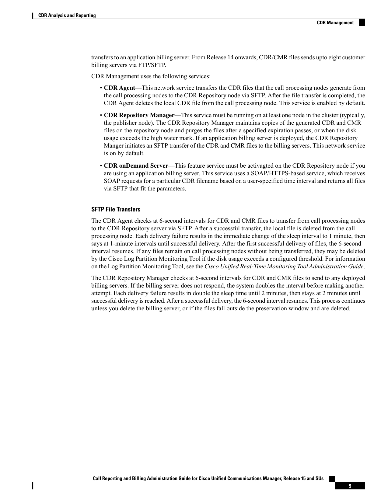
• CDR Agent—This network service transfers the CDR files that the call processing nodes generate from
the call processing nodes to the CDR Repository node via SFTP. After the file transfer is completed, the
CDR Agent deletes the local CDR file from the call processing node. This service is enabled by default.
• CDR Repository Manager—This service must be running on at least one node in the cluster (typically,
the publisher node). The CDR Repository Manager maintains copies of the generated CDR and CMR
files on the repository node and purges the files after a specified expiration passes, or when the disk
usage exceeds the high water mark. If an application billing server is deployed, the CDR Repository
Manger initiates an SFTP transfer of the CDR and CMR files to the billing servers. This network service
is on by default.
• CDR onDemand Server—This feature service must be activagted on the CDR Repository node if you
are using an application billing server. This service uses a SOAP/HTTPS-based service, which receives
SOAP requests for a particular CDR filename based on a user-specified time interval and returns all files
via SFTP that fit the parameters.
SFTP File Transfers
The CDR Agent checks at 6-second intervals for CDR and CMR files to transfer from call processing nodes
to the CDR Repository server via SFTP. After a successful transfer, the local file is deleted from the call
processing node. Each delivery failure results in the immediate change of the sleep interval to 1 minute, then
says at 1-minute intervals until successful delivery. After the first successful delivery of files, the 6-second
interval resumes. If any files remain on call processing nodes without being transferred, they may be deleted
by the Cisco Log Partition Monitoring Tool if the disk usage exceeds a configured threshold. For information
on the Log Partition Monitoring Tool, see the Cisco Unified Real-Time Monitoring Tool Administration Guide.
The CDR Repository Manager checks at 6-second intervals for CDR and CMR files to send to any deployed
billing servers. If the billing server does not respond, the system doubles the interval before making another
attempt. Each delivery failure results in double the sleep time until 2 minutes, then stays at 2 minutes until
successful delivery is reached. After a successful delivery, the 6-second interval resumes. This process continues
unless you delete the billing server, or if the files fall outside the preservation window and are deleted.
Call Reporting and Billing Administration Guide for Cisco Unified Communications Manager, Release 15 and SUs
9
CDR Analysis and Reporting
CDR Management
Page 22
Supported SFTP Servers
For internal testing, Cisco uses the SFTP Server on Cisco Prime Collaboration Deployment (PCD) which is
provided by Cisco, and which is supported by Cisco TAC. Refer to the following table for a summary of SFTP
server options:
Use the information in the following table to determine which SFTP server solution to use in your system.
Table 3: SFTP Server Information
Information
SFTP Server
This server is the only SFTP server that is provided and tested by Cisco, and fully
supported by Cisco TAC.
Version compatibility depends on your version of Unified Communications
Manager and Cisco Prime Collaboration Deployment. See the Cisco Prime
Collaboration Deployment Administration Guide before you upgrade its version
(SFTP) or Unified Communications Manager to ensure that the versions are
compatible.
SFTP Server on Cisco
Prime Collaboration
Deployment
These SFTP servers from a technology partner are third-party provided and
third-party tested. Version compatibility depends on the third party test. See the
Technology Partner page if you upgrade their SFTP product and/or upgrade
Unified Communications Manager for which versions are compatible.
SFTP Server from a
Technology Partner
Call Reporting and Billing Administration Guide for Cisco Unified Communications Manager, Release 15 and SUs
10
CDR Analysis and Reporting
CDR Management
Page 23
Information
SFTP Server
These SFTP servers are provided by a third party and are not officially supported
by Cisco TAC.
Version compatibility is on a best effort basis to establish compatible SFTP
versions and Unified Communications Manager versions.
Note
These products have not been tested by Cisco and we cannot guarantee
functionality. Cisco TAC does not support these products. For a fully tested and
supported SFTP solution, use Cisco Prime Collaboration Deployment or a
Technology Partner.
SFTP Server from another
Third Party
Roles
CAR provides reporting capabilities for three levels of users:
• Administrators use all the features of CDR Analysis and Reporting; for example, they can generate
system reports to help with load balancing, system performance, and troubleshooting.
• Managers can generate reports for users, departments, and QoS to help with call monitoring for budgeting
or security purposes and for determining the voice quality of the calls.
• Individual users can generate a billing report for calls.
Any user can act as a CAR administrator. Users who have been identified as CAR administrators have full
control over the CAR system. The administrator can modify all the parameters that relate to the system and
the reports.
CAR requires a minimum of one administrator.
You set up administrators, managers, and users in Cisco Unified CM Administration. For more information,
see the Generate CAR Users, on page 25.
Reports
From CAR, you can generate reports on demand, or if you are an administrator, you can schedule reports for
an automatic generation. You can view reports in Comma Separated Values (CSV) format or Portable Document
Format (PDF). If you choose PDF, you must have Adobe Acrobat Reader that installed on your PC.
Report Information
For all CAR reports that show the pattern for Hour of Day, Day of Week, and Day of Month, the charts and
tables get shown according to the following conditions:
• When no records match the time range that is specified (hour of the day, day of the week, or day of the
month) in the search criteria, the report displays a value of 0.00 for all the days/hours.
• If all records that are returned have a value of 0.00, CAR does not display the charts. CAR displays the
charts if any record contains a non-zero value.
• When records get generated (for at least one day in the chosen date range) and the number of days that
is chosen is more than the number of days that the report can show (more than seven for weekly and
Call Reporting and Billing Administration Guide for Cisco Unified Communications Manager, Release 15 and SUs
11
CDR Analysis and Reporting
Roles
Page 24
more than 31 for monthly), the chart displays all the days (with 0 value for the days that do not generate
records). A table displays for all the days with relevant value and 0.00 for the days that do not contain
data.
• When records generate (for at least one day in the chosen date range) and the number of days that is
chosen is less than the number of days that the report can show (less than 7 for weekly and less than 31
for monthly), the chart displays all the days (with 0 value for the days that do not generate records). A
table displays all the days with relevant value and 0.00 for the days that do not contain data.
In all the CAR reports that display the username, userid displays if CAR cannot retrieve the username. This
situation can occur when the report gets generated for prior data where the user that was involved in a call
then no longer exists in the system (Unified Communications Manager database).
Generated Report Schedule
Automatically generating reports comprises a two-step process. First, you must enable the reports that you
want to have generated. Second, you must schedule the reports for the day and time that you want them to
generate. CAR provides a default schedule, so if the default schedule is acceptable, you need only enable the
reports that you want to automatically generate.
Reports and email alerts do not automatically get enabled on a new installation. You must enable the reports
that you want to automatically generate. To enable or disable a report generation, see the Enable Automatic
Generation Reports, on page 57 for instructions on how to generate reports and emails automatically.
To change the specific time each day, week, or month that reports get generated and get purged from the
system, see Set Up CDR Load Schedule, on page 36.
Audit Logging
With audit logging, any configuration change to the Unified Communications Manager system gets logged
in separate log files for auditing. An audit event is any event that is required to be logged. Cisco Unified CDR
Analysis and Reporting create audit logs for these events:
• Scheduling the CDR Loader.
• Scheduling the daily, weekly, and monthly user reports, system reports, and device reports.
• Mail parameters configurations.
• Dial plan configurations.
• Gateway configurations.
• System preferences configurations.
• Autopurge configurations.
• Rating engine configurations for the duration, time of day, and voice quality.
• QoS configurations.
• Automatic generation/alert of pre-generated reports configurations.
• Notification limits configurations.
Call Reporting and Billing Administration Guide for Cisco Unified Communications Manager, Release 15 and SUs
12
CDR Analysis and Reporting
Generated Report Schedule
Page 25
Log-On Message
You can upload a text file that contains a customized log-on message that appears on the initial Cisco Unified
Communications Manager CDR Analysis and Reporting window.
For more information and the procedure for uploading your customized log-on message, see the Administration
Guide for Cisco Unified Communications Manager.
Internationalization
CAR, designed to be internationalized to handle any locale (or language), includes a database that can also
handle any locale.
CAR supports all Latin-1 language and Unicode language locales as Unified Communications Manager the
help specifies. Latin-1 languages include English and Western European languages. Unicode languages include
Japanese and Chinese.
Note
Two types of locale exist: user and network. Each locale comprises a set of locale files. The following definitions
describe the two types of files:
• User - Files that relate to user-related functions, such as phone display text, user applications, and user
web pages.
• Network - Files that relate to network-related functions, such as phone and gateway tones. Country names
designate network locales.
CAR supports the locales only if the Locale Installer has installed locales.
For Unified Communications Manager, make sure that you have first installed the Unified Communications
Manager Locale Installer on every server in the cluster. Installing the Locale Installer ensures that you have
the latest translated text available for CAR.
For more information about the Unified Communications Manager Locale Installer, see the Administration
Guide for Cisco Unified Communications Manager.
Note
Only User and Manager windows support multiple locales. Administrator windows display in English.
In the Cisco Unified CM Administration, set the user-preferred locale in the Unified Communications Manager
database. You do this when you create a user from the End User Configuration window. Specify the preferred
locale along with the username, user ID, and so on. The Unified Communications Manager database stores
this information.
For more detailed information, see the Cisco Unified Communications Manager Online Help.
These sections describe the elements that make up the internationalization of CAR.
Logon Page
When the client (browser) requests the logon information, the logon window header includes the most preferred
locale of the client. The CAR system checks whether the CAR UI supports this locale. If the CAR UI does
Call Reporting and Billing Administration Guide for Cisco Unified Communications Manager, Release 15 and SUs
13
CDR Analysis and Reporting
Log-On Message

Page 26
not support the locale, or if the locale is not installed in the system, the logon window displays in the Unified
Communications Manager system default locale that is set in the CiscoCommunications Manager Enterprise
parameter. If CAR does not also support this locale, or the locale is not installed in the system, the locale gets
set to English_United_States.
Authenticate and Show CAR Pages for Post Logon Windows
User credentials (in any language) get authenticated through the Unified Communications Manager database,
and then CAR windows for non-administrative users (users or managers) display the user preferred locale. If
the CAR UI does not support this locale, or if the locale is not installed in the system, the Unified
Communications Manager system default locale gets used. If this locale is not supported by CAR or is not
installed in the system, windows display in the most preferred locale of the browser. When the browser-preferred
locale is also not supported or not installed, the locale gets set to English_United_States. All information on
the UI windows, including labels, number formats, and so on, displays based on the locale. The administrator
windows always display in English.
Reports
Reports, which are generated in both CSV and PDF formats, display in the user preferred locale for
non-administrative users (users or managers). However, the dynamic data (like the Company Name shown
in the report header) displays in the same language as was used to enter it in the database. The locale provides
the basis for the header, footers, number formats, and some static data (like call classification). Reports for
administrators display in English.
Online Help
To access CAR documentation online help, choose Help > Contents and Index (for a list of contents) or
Help > For this page (for information that is specific to the page that displays.)
Backup Database
The CAR and CDR Disaster Recovery Service (DRS) now integrates into the Unified Communications
Manager DRS. The DRS includes the backup of the CAR database, pre-generated reports, and the CDR
preserved flat files.
The CAR Web Service and CAR Scheduler automatically stop before the backup and restore process begin,
and automatically restart after the backup and restore process is complete.
The table displays the features and components that the Disaster Recovery System can back up and restore.
For each feature that you choose, the system backs up all its components automatically.
Call Reporting and Billing Administration Guide for Cisco Unified Communications Manager, Release 15 and SUs
14
CDR Analysis and Reporting
Online Help
Page 27
Table 4: Cisco Unified CM Features and Components
Components
Feature
Unified Communications Manager database
CCM - Unified Communications Manager
Platform
Serviceability
Music On Hold (MOH)
Cisco Emergency Responder
Bulk Tool (BAT)
Preference
Phone device files (TFTP)
syslogagt (SNMP syslog agent)
cdpagent (SNMP cdp agent)
tct (trace collection tool)
Call Detail Records (CDRs)
CDR Reporting and Analysis (CAR)
For more detailed information, see the Administration Guide for Cisco Unified Communications Manager.
CPU Utilization
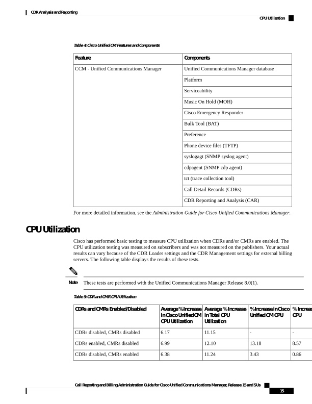
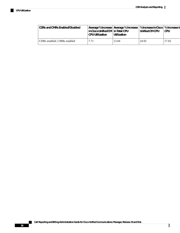
Cisco has performed basic testing to measure CPU utilization when CDRs and/or CMRs are enabled. The
CPU utilization testing was measured on subscribers and was not measured on the publishers. Your actual
results can vary because of the CDR Loader settings and the CDR Management settings for external billing
servers. The following table displays the results of these tests.
These tests are performed with the Unified Communications Manager Release 8.0(1).
Note
Table 5: CDR and CMR CPU Utilization
% Increas
CPU
% Increase in Cisco
Unified CM CPU
Average % Increase
in Total CPU
Utilization
Average % Increase
in Cisco Unified CM
CPU Utilization
CDRs and CMRs Enabled/Disabled
11.15
6.17
CDRs disabled, CMRs disabled
8.57
13.18
12.10
6.99
CDRs enabled, CMRs disabled
0.86
3.43
11.24
6.38
CDRs disabled, CMRs enabled
Call Reporting and Billing Administration Guide for Cisco Unified Communications Manager, Release 15 and SUs
15
CDR Analysis and Reporting
CPU Utilization

Page 28
% Increase in
CPU
% Increase in Cisco
Unified CM CPU
Average % Increase
in Total CPU
Utilization
Average % Increase
in Cisco Unified CM
CPU Utilization
CDRs and CMRs Enabled/Disabled
17.02
24.92
13.04
7.71
CDRs enabled, CMRs enabled
Call Reporting and Billing Administration Guide for Cisco Unified Communications Manager, Release 15 and SUs
16
CDR Analysis and Reporting
CPU Utilization
Page 29
C H A P T E R 3
Initial Setup
• CDR Analysis and Reporting Configuration Overview, on page 17
• CDR Analysis and Reporting Initial Setup, on page 18
CDR Analysis and Reporting Configuration Overview
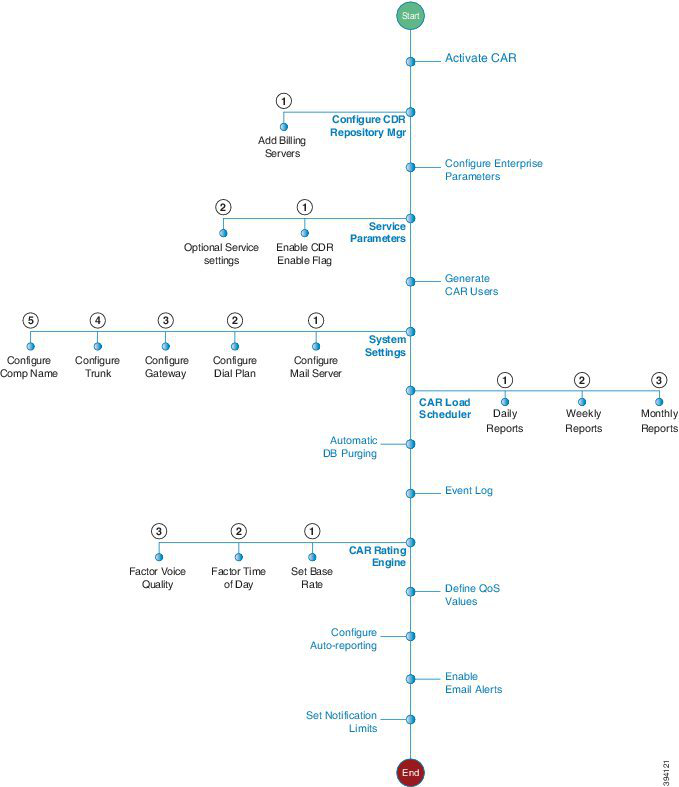
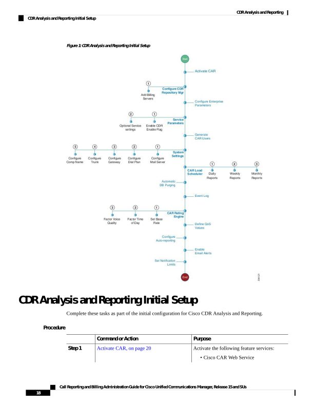
The following diagram illustrates the initial system configuration for Cisco CDR Analysis and Reporting.
Call Reporting and Billing Administration Guide for Cisco Unified Communications Manager, Release 15 and SUs
17

Page 30
Figure 1: CDR Analysis and Reporting Initial Setup
CDR Analysis and Reporting Initial Setup
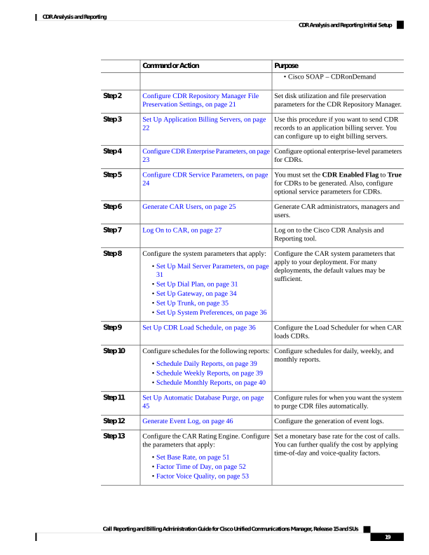
Complete these tasks as part of the initial configuration for Cisco CDR Analysis and Reporting.
Procedure
Purpose
Command or Action
Activate the following feature services:
Activate CAR, on page 20
Step 1
• Cisco CAR Web Service
Call Reporting and Billing Administration Guide for Cisco Unified Communications Manager, Release 15 and SUs
18
CDR Analysis and Reporting
CDR Analysis and Reporting Initial Setup
Page 31
Purpose
Command or Action
• Cisco SOAP – CDRonDemand
Set disk utilization and file preservation
parameters for the CDR Repository Manager.
Configure CDR Repository Manager File
Preservation Settings, on page 21
Step 2
Use this procedure if you want to send CDR
records to an application billing server. You
can configure up to eight billing servers.
Set Up Application Billing Servers, on page
22
Step 3
Configure optional enterprise-level parameters
for CDRs.
Configure CDR Enterprise Parameters, on page
23
Step 4
You must set the CDR Enabled Flag to True
for CDRs to be generated. Also, configure
optional service parameters for CDRs.
Configure CDR Service Parameters, on page
24
Step 5
Generate CAR administrators, managers and
users.
Generate CAR Users, on page 25
Step 6
Log on to the Cisco CDR Analysis and
Reporting tool.
Log On to CAR, on page 27
Step 7
Configure the CAR system parameters that
apply to your deployment. For many
Configure the system parameters that apply:
Step 8
• Set Up Mail Server Parameters, on page
31
deployments, the default values may be
sufficient.
• Set Up Dial Plan, on page 31
• Set Up Gateway, on page 34
• Set Up Trunk, on page 35
• Set Up System Preferences, on page 36
Configure the Load Scheduler for when CAR
loads CDRs.
Set Up CDR Load Schedule, on page 36
Step 9
Configure schedules for daily, weekly, and
monthly reports.
Configure schedules for the following reports:
Step 10
• Schedule Daily Reports, on page 39
• Schedule Weekly Reports, on page 39
• Schedule Monthly Reports, on page 40
Configure rules for when you want the system
to purge CDR files automatically.
Set Up Automatic Database Purge, on page
45
Step 11
Configure the generation of event logs.
Generate Event Log, on page 46
Step 12
Set a monetary base rate for the cost of calls.
You can further qualify the cost by applying
time-of-day and voice-quality factors.
Configure the CAR Rating Engine. Configure
the parameters that apply:
Step 13
• Set Base Rate, on page 51
• Factor Time of Day, on page 52
• Factor Voice Quality, on page 53
Call Reporting and Billing Administration Guide for Cisco Unified Communications Manager, Release 15 and SUs
19
CDR Analysis and Reporting
CDR Analysis and Reporting Initial Setup
Page 32
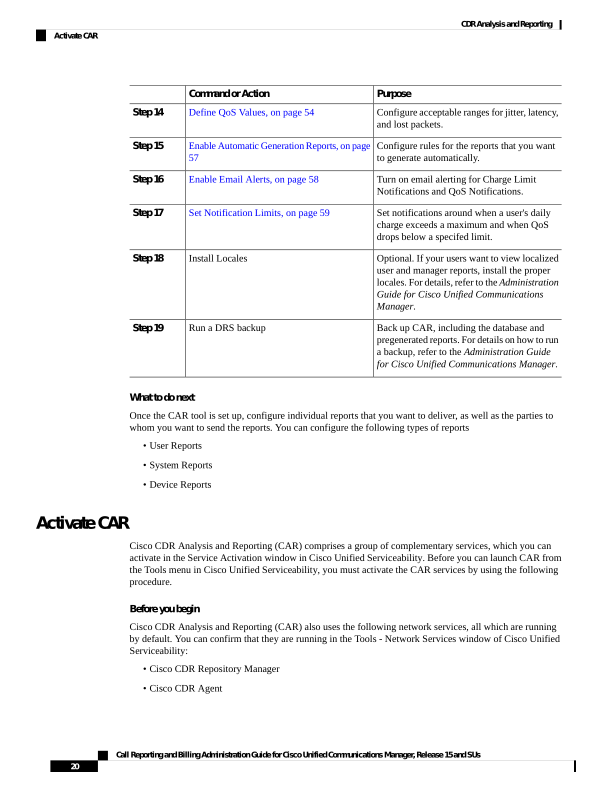
Purpose
Command or Action
Configure acceptable ranges for jitter, latency,
and lost packets.
Define QoS Values, on page 54
Step 14
Configure rules for the reports that you want
to generate automatically.
Enable Automatic Generation Reports, on page
57
Step 15
Turn on email alerting for Charge Limit
Notifications and QoS Notifications.
Enable Email Alerts, on page 58
Step 16
Set notifications around when a user's daily
charge exceeds a maximum and when QoS
drops below a specifed limit.
Set Notification Limits, on page 59
Step 17
Optional. If your users want to view localized
user and manager reports, install the proper
Install Locales
Step 18
locales. For details, refer to the Administration
Guide for Cisco Unified Communications
Manager.
Back up CAR, including the database and
pregenerated reports. For details on how to run
Run a DRS backup
Step 19
a backup, refer to the Administration Guide
for Cisco Unified Communications Manager.
What to do next
Once the CAR tool is set up, configure individual reports that you want to deliver, as well as the parties to
whom you want to send the reports. You can configure the following types of reports
• User Reports
• System Reports
• Device Reports
Activate CAR
Cisco CDR Analysis and Reporting (CAR) comprises a group of complementary services, which you can
activate in the Service Activation window in Cisco Unified Serviceability. Before you can launch CAR from
the Tools menu in Cisco Unified Serviceability, you must activate the CAR services by using the following
procedure.
Before you begin
Cisco CDR Analysis and Reporting (CAR) also uses the following network services, all which are running
by default. You can confirm that they are running in the Tools - Network Services window of Cisco Unified
Serviceability:
• Cisco CDR Repository Manager
• Cisco CDR Agent
Call Reporting and Billing Administration Guide for Cisco Unified Communications Manager, Release 15 and SUs
20
CDR Analysis and Reporting
Activate CAR
Page 33
• Cisco CAR Scheduler
• Cisco SOAP - CallRecord Service
• Cisco CAR DB
Procedure
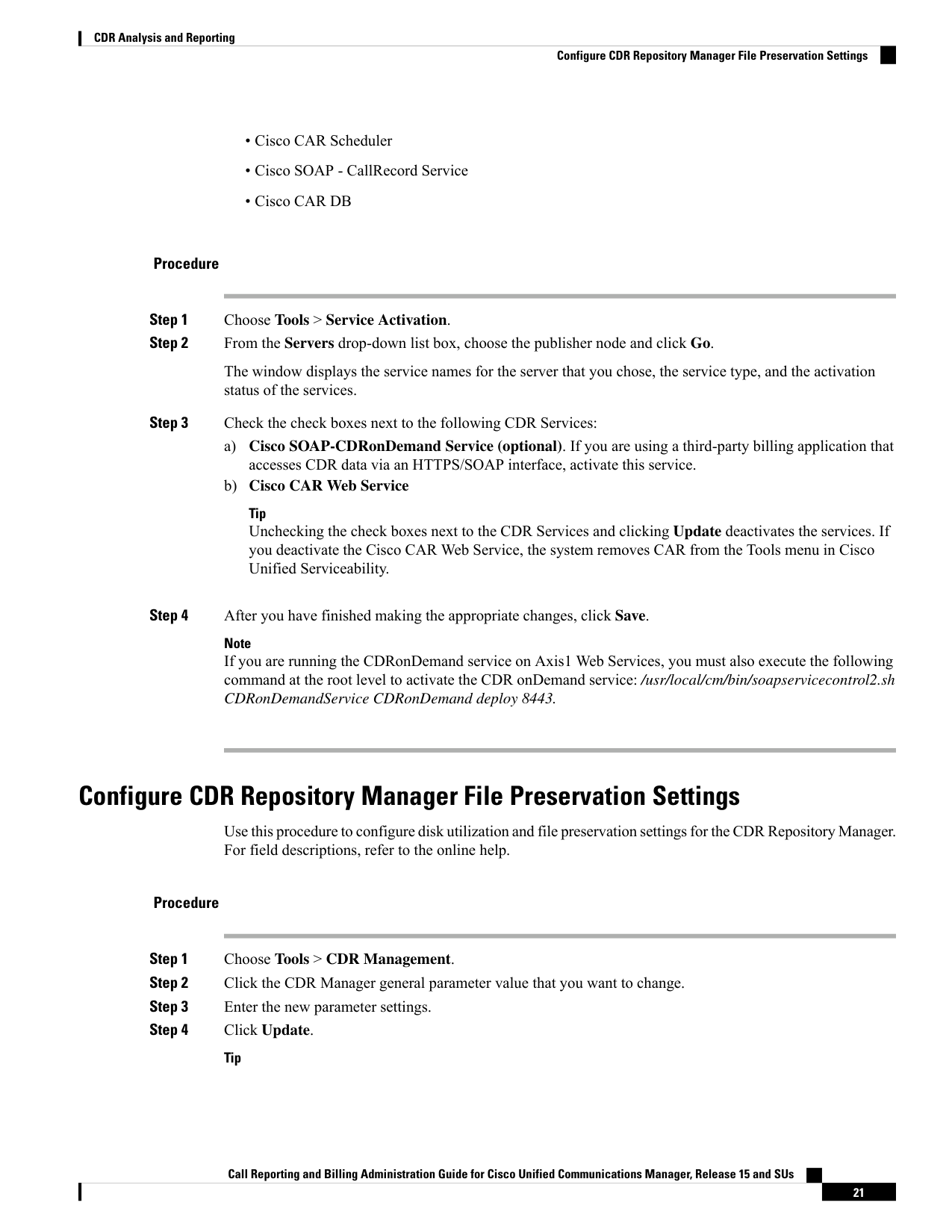
Step 1
Choose Tools > Service Activation.
Step 2
From the Servers drop-down list box, choose the publisher node and click Go.
The window displays the service names for the server that you chose, the service type, and the activation
status of the services.
Step 3
Check the check boxes next to the following CDR Services:
a)
Cisco SOAP-CDRonDemand Service (optional). If you are using a third-party billing application that
accesses CDR data via an HTTPS/SOAP interface, activate this service.
b) Cisco CAR Web Service
Tip
Unchecking the check boxes next to the CDR Services and clicking Update deactivates the services. If
you deactivate the Cisco CAR Web Service, the system removes CAR from the Tools menu in Cisco
Unified Serviceability.
Step 4
After you have finished making the appropriate changes, click Save.
Note
If you are running the CDRonDemand service on Axis1 Web Services, you must also execute the following
command at the root level to activate the CDR onDemand service: /usr/local/cm/bin/soapservicecontrol2.sh
CDRonDemandService CDRonDemand deploy 8443.
Configure CDR Repository Manager File Preservation Settings
Use this procedure to configure disk utilization and file preservation settings for the CDR Repository Manager.
For field descriptions, refer to the online help.
Procedure
Step 1
Choose Tools > CDR Management.
Step 2
Click the CDR Manager general parameter value that you want to change.
Step 3
Enter the new parameter settings.
Step 4
Click Update.
Tip
Call Reporting and Billing Administration Guide for Cisco Unified Communications Manager, Release 15 and SUs
21
CDR Analysis and Reporting
Configure CDR Repository Manager File Preservation Settings
Page 34
At any time, you can click Set Default to specify the default values. After you set the defaults, click Update
to save the default values.
Set Up Application Billing Servers
Use the following procedure if you want to deploy application billing servers to which you will send CDRs.
You can configure up to eight billing servers.
Cipher Support
For Unified Communications Manager 11.5, Unified Communications Manager advertises the following CBC
and CTR ciphers for SFTP connections:
• aes128-cbc
• 3des-cbc
• aes128-ctr
• aes192-ctr
• aes256-ctr
Make sure that the backup SFTP Server supports one of these ciphers to communicate with Unified
Communications Manager.
Note
From Unified Communications Manager 12.0 release onwards, CBC ciphers are not supported. Unified
Communications Manager supports and advertises only the following CTR ciphers:
• aes256-ctr
• aes128-ctr
• aes192-ctr
Make sure that the backup SFTP Server supports one of these CTR ciphers to communicate with Unified
Communications Manager.
Note
Procedure
Step 1
Choose Tools > CDR Management Configuration.
The CDR Management Configuration window displays.
Step 2
Perform one of the following tasks:
• To add a new application billing server, click the Add New button.
Call Reporting and Billing Administration Guide for Cisco Unified Communications Manager, Release 15 and SUs
22
CDR Analysis and Reporting
Set Up Application Billing Servers

Page 35
• To update an existing application billing server, click the server hostname/IP address.
Step 3
Enter the application billing server parameter settings.
Step 4
Click Add or Update.
Billing Server Authentication Issue
If you have a billing server that is deployed with SFTP, and you are using a non-default cipher that you
configured on both Unified Communications Manager and on the billing server, a connection issue may result
if you restart a Unified Communications Manager server, or if you restart the Cisco CallManager service. If
this occurs, the billing server is unable to authenticate and the connection are broken.
After the restart, Unified Communications Manager advertises only the default ciphers and will not advertise
any new ciphers that you installed, which will result in an authentication issue if you are using a non-default
cipher. If you run into this issue, generate a new key and reset the connection:
Procedure
Step 1
Choose Tools > CDR Management.
The CDR Management Configuration window displays.
Step 2
Under Billing Application Server Parameters, locate your billing server.
Step 3
Click Reset to generate a new key that corresponds to your billing server.
After the reset, Unified Communications Manager advertises the default ciphers, and some additional ciphers.
The billing server must have one of these ciphers that are installed to restore the communication.
Configure CDR Enterprise Parameters
Use this procedure to configure optional enterprise parameters for CDRs. For detailed field descriptions, click
the parameter name in the GUI to access enterprise parameter help.
Procedure
Step 1
From Cisco Unified CM Administration, choose System > Enterprise Parameters.
Step 2
Under CDR Parameters, configure values for the following parameters. For detailed field descriptions, click
the parameter name in the GUI:
• CDR File Time Interval—The time interval for collecting CDR data. For example, a value of 1 means
each CDR file contains 1 minute of CDR data.
• Cluster ID—Assign a unique identifier for the cluster.
Step 3
Under CCM Web Service Parameters, configure values for the following parameters:
Call Reporting and Billing Administration Guide for Cisco Unified Communications Manager, Release 15 and SUs
23
CDR Analysis and Reporting
Billing Server Authentication Issue
Page 36
• Allowed CDRonDemand get_file Queries Per Minute—The maximum number of CDRonDemand
get_file queries per minute
• Allowed CDRonDemand get_file_list Queries Per Minute—The maximum number of CDRonDemand
get_list queries per minute.
Step 4
Click Save.
Configure CDR Service Parameters
Use this procedure to configure service parameters for CDR Analysis and Reporting. For example, the CDR
Enabled Flag must be set to True for CDRs to be generated.
Procedure
Step 1
From Cisco Unified CM Administration, choose System > Service Parameters.
Step 2
From the Server drop-down, choose a Unified Communications Manager node.
Step 3
From the Service drop-down, choose Cisco CallManager.
Step 4
Click Advanced.
Step 5
Under System, configure values for the following parameters:.
• CDR Enabled Flag—This parameter must be set to True for CDRs to be generated. By default, this
parameter is disabled.
• CDR Log Calls with Zero Duration Flag—Set this parameter to True if you want to log call detail
records (CDRs) for calls that never connected or that lasted less than 1 second.
Step 6
Under Clusterwide Parameters (Device - General), set the following optional parameters:
• Display FAC in CDR—Determines whether the FAC associated with a call displays in the CDR record.
• Show Line Group Member DN in finalCalled PartyNumber CDR Field—Determines whether the
the finalCalledPartyNumber field in the CDR shows the directory number (DN) of the line group member
who answered the call or the hunt pilot DN.
• Show Line Group Member Non Masked DN in finalCalledPartyNumber CDR Field—Determines
whether the finalCalledPartyNumber field in the CDR shows the directory number (DN) or the DN
applied with external phone number mask of the line group member who answered the call or the hunt
pilot DN.
Step 7
Under Clusterwide Parameters (Device - Phone), set the Add Incoming Number Prefix to CDR parameter
to True if you want the system to add the incoming number prefix (for example, a National Number Prefix
or Subscriber Number Prefix) to the CDR record. The default setting is False.
Example
Following is an example of how the Add Incoming Number Prefix to CDR parameter works on
the inbound and outbound side of the call.
If the parameter is set to False, the CDR will contain the prefix that is added to the call when the
type of number is a National number or Subscriber number.
Call Reporting and Billing Administration Guide for Cisco Unified Communications Manager, Release 15 and SUs
24
CDR Analysis and Reporting
Configure CDR Service Parameters
Page 37
If the parameter is set to True, the CDR contains the prefix that is added to the calling party number
when the type of number is a:
• National number
• International number only when the destination is not a gateway
• Subscriber number
• Unknown number only when the destination is not a gateway
Outbound Side of Call
Inbound Side of Call
1214
National Number Prefix
011
International Number Prefix
214
Subscriber Number Prefix
972
Unknown Number Prefix
Generate CAR Users
Any user can act as a CAR administrator (including application users). However, you must add the end user
to an access control group that provides access to the CAR tool (such as Standard CAR Admin Users or
Standard CCM Super Users). End users who have been identified as CAR administrators have full control
over the CAR system. The administrator can modify all the parameters that relate to the system and the reports.
End users who have not been identified as CAR administrators can access only designated CAR reports.
If you decide to create a customized access control group, rather than the predefined default groups, your
customized group must include the Standard Admin Rep Tool Admin role. For details on how to configure
user access, refer to the Administration Guide for Cisco Unified Communications Manager.
Note
To use CAR, ensure that at least one CAR administrator exists in the Unified Communications Manager
database.
Tip
Before you log in to CAR, you must configure at least one CAR user that has administrative privileges in
CAR. To configure CAR administrators, managers, and users, perform the following procedure:
Procedure
Step 1
In Cisco Unified CM Administration, add an end user by choosing User Management > End User. For
additional information on how to perform this task, see the Cisco Unified Communications Manager
Administration Guide. To create a manager, make sure that you enter a value in the Manager User ID field.
Note
Call Reporting and Billing Administration Guide for Cisco Unified Communications Manager, Release 15 and SUs
25
CDR Analysis and Reporting
Generate CAR Users


Page 38
After creating the End User, edit the user password credentials by clicking the button Edit Credentials near
the password text box. Uncheck the User Must Change at Next Login check box. If this action is not taken,
you will get IMS_ERROR_CODE_5 (See Log On to CAR, on page 27) and will not be allowed to log in to
CAR. Then, you must log in to Cisco Unified CM Administration to manually reset the password.
Tip
Cisco recommends that you configure at least one CAR user that has administrative privileges in CAR before
you start using CAR. If you have not configured a CAR administrator or want to configure another CAR
administrator, continue with this procedure.
Step 2
Choose User Management > Access Control Group.
Step 3
Click Find to view the list of access control groups.
Step 4
Select an access control group that provides CAR access. For example, Standard CAR Admin Users or
Standard CCM Super Users.
Step 5
Click Add End Users to Group.
Step 6
Check the check boxes for the users that you want to add to the group and click Add Selected.
The user displays in the Users in Group group box.
Tip
To revoke CAR administrative privileges, check the check box of the user in Users in Group group box and
click Delete Selected. When the warning message displays, click OK. The system revokes the privileges
immediately.
An application user that acts as a CAR administrator can configure all reports except the Individual Bill report.
An application user that acts as a CAR administrator cannot access end user (CCM user) windows. CAR
notifications do not get sent to the application user because no mail ID exists for the application user.
Note
CAR System Settings
CDR Analysis and Reporting set default values for all system parameters. Before you generate any reports in
CAR, Cisco recommends that you customize several system parameters. Because default values are provided
for all system parameters, Cisco recommends customizing but does not require it.
The following system parameters refer to the CAR system parameters. Be aware that they are separate and
distinct from the Unified Communications Manager enterprise and service parameters that are discussed in
the previous sections.
Note
CAR allows you to set the following parameters:
• Mail server criteria - CAR uses this information to successfully connect to the email server to send alerts
and reports by email. If you do not want to send alerts or reports by email, you do not need to specify
this information.
Call Reporting and Billing Administration Guide for Cisco Unified Communications Manager, Release 15 and SUs
26
CDR Analysis and Reporting
CAR System Settings

Page 39
• Dial plan - The default dial plan in CAR specifies the North American numbering plan (NANP). Ensure
that the dial plan is properly configured, so call classifications are correct in the reports. If you have
modified the default NANP that Cisco Unified CM Administration provides, or if you are outside the
NANP, be sure to configure the dial plan according to your Unified Communications Manager dial plan.
• Gateways - To utilize the gateway reports, you need to configure gateways in CAR. You should do this
after installation of any existing gateways in your Cisco IP telephony system and when you add gateways
to the system. If the system deletes any gateways, CAR gets the latest list of gateways, and any
configuration that is specified in CAR for the deleted gateways gets deleted. CAR uses the area code
information to determine whether calls are local or long distance. You must provide the Number of Ports
information for each gateway to enable CAR to generate the Utilization reports.
• System preferences - You can set CAR system preferences for the Company Name parameter.
Log On to CAR
Only CAR administrators and normal end users can log on to the CAR web interface. Users do not need to
be a member of a standard CAR administrator group to be a CAR administrator. Any user who has the role
“Standard Admin Rep Tool Admin” associated with the user ID can access CAR as a CAR administrator.
The user ID role association gets done by adding the user to a user group that has the role that is associated
with it. “Standard CAR Admin Group” and “Standard CCM Super Users” comprise two groups that have the
role “Standard Admin Rep Tool Admin” associated with them. The default application user that gets created
at installation, who is a member of the “Standard CCM Super Users” group, can log in to CAR as a CAR
administrator but only as an application user. This user cannot access the Individual Bills report.
CAR supports custom CAR Admin groups. Any custom group that has the role “Standard CAR Admin Group”
associated with it can add users who are considered to be CAR administrators when logging into the CAR
web interface.
End users who are not CAR administrators can log in to CAR only if they have the role “Standard CCM End
Users” associated with them. You can do this user ID - role association by adding the end user to the “Standard
CCM End Users” group or any other group that has the specified role associated. Any end user without the
“Standard CCM End Users” group association cannot log in to the CAR web interface.
Any user without the “Standard CCM End Users” or “Standard Admin Rep Tool Admin” role cannot log in
to CAR. An attempt by this user to log in to CAR generates a 403 error, and the user gets redirected to the
login window with no error message. CAR Web Service traces will log the username of the user who tried to
access the application.
CAR facilitates users to change their password by using a Change Password window if the user password has
expired. When users with an expired password try to log into CAR, they receive IMS_Error_Code 5, 6, or 8.
CAR uses the ChangePasswordFilter of ccmadmin to redirect the user to change-password.jsp when any of
the preceding error codes are received.
The database throttle limits the concurrent users to 100; because of this limit, IMS also supports only 100
users with a login rate of approximately 112 ms.
Note
If an error occurs while you are resetting the user password, the following message displays on the
Change-Password window: “System error while changing password for user. Please contact system
administrator.”
Call Reporting and Billing Administration Guide for Cisco Unified Communications Manager, Release 15 and SUs
27
CDR Analysis and Reporting
Log On to CAR

Page 40
Even though the CAR Administrator status extends to any user with the role “Standard Admin Rep Tool
Admin,” CAR notifications, alerts, and pregen reports only get sent to users who are members of the group
“Standard CAR Admin Group” and not all CAR administrators.
To log on to CAR, perform the following procedure:
Before you begin
Perform the following tasks:
• Before you can log in to CAR, verify that the Cisco CAR Web Service and the CiscoCAR Scheduler
service that is run on the first server. After you activate the services, the option CDR Analysis and
Reporting displays under the Tools menu in Cisco Unified Serviceability. For information on how to
activate services, see the Activate CAR, on page 20.
• Configure CAR administrators, managers, and users as described in Generate CAR Users, on page 25.
Procedure
Step 1
To log on to CAR, perform one of the following tasks:
a)
For CAR system administrators only - From Cisco Unified Serviceability, choose Tools > CDR Analysis
and Reporting.
b) For CAR users or administrators - From the web browser, enter https://<Server-ip/name>:8443/car/
Step 2
After the CAR logon window displays, enter your user ID in the User Name field.
Step 3
In the Password field, enter your password. Click Login.
The CAR window displays.
If the user ID or password is invalid, CAR displays one of the Identity Management System (IMS) messages
that are listed in the following table.
Table 6: CAR Invalid Logon Messages
Message
Error Code
Either the User Name or the Password entered is
invalid. Ensure that you are logging into CAR as a
CAR administrator or a regular End User.
IMS_ERROR_CODE 1
The account has been locked by System
Administrator. Please contact the administrator.
IMS_ERROR_CODE 2
The account has been temporarily locked. Please
contact the System Administrator or try after
sometime.
IMS_ERROR_CODE 3
The account has been deactivated due to lack of
activity. Please contact the System Administrator.
IMS_ERROR_CODE 4
The account has been locked as the password has
expired. Please reset the password or contact the
System Administrator.
IMS_ERROR_CODE 5
Call Reporting and Billing Administration Guide for Cisco Unified Communications Manager, Release 15 and SUs
28
CDR Analysis and Reporting
Log On to CAR
Page 41
Message
Error Code
The account has been locked as the password has
expired. Please contact the System Administrator.
IMS_ERROR_CODE 6
The system has changed over to using LDAP
authentication and the user is still in the old database.
Please contact the System Administrator. This error
code is not used for Cisco Unified Communications
Manager Business Edition 5000.
IMS_ERROR_CODE 7 = ERROR:
LDAP_INACTIVE
The account has been locked as the user needs to log
in manually and change the credential first. Please
reset the password from the Cisco Unified
Communications Manager Administrationpage or
contact the System Administrator.
IMS_ERROR_CODE 8
System error. Please contact the System
Administrator.
IMS_ERROR_CODE UNKNOWN
Unable to Authenticate User due to System Error.
Please contact System Administrator.
IMS_EXCEPTION (any exception returned by IMS)
= AUTHENTICATION FAILURE
After you log on to CAR, the following warning messages are displayed on a dashboard, if any:
• Displays a list of nodes where CallManager service is activated but CDR Enabled flag is not enabled.
Also, specifies that the CDRs will not be generated on the listed nodes.
• If cluster wide parameter Call Diagnostics Enabled flag is disabled, it displays that the flag is disabled
and states that the QoS information will not be generated on calls.
• Displays the status of CAR Scheduler service and Cisco Repository Manager Service, if they are stopped
on publisher.
• Displays the breach status, if either the limit 2M or HWM is breached.
• Displays the status of CDR loader.
• Last run of CAR Loader is interrupted, please check the CAR Scheduler Logs for more information.
a)
If the loader is disabled, it states that the loader is disabled.
b) If the loader is enabled, it checks for the last load status of CDR loader. If the last load status of CDR
loader is failed, it displays that the loading of CDR loader is failed and informs you to check the CAR
scheduler logs. If the CDR loader is interrupted by DRS backup or restore activity, or if the Cisco CAR
Scheduler service restarts, it displays the message: Last run of CAR Loader is interrupted,
please check the CAR Scheduler Logs for more information.
1.
If any of the Tbl_System_Preferences table columns does not have expected values, the dashboard
displays the exceptions along with a Restore Defaults button. You can click the Restore Defaults
button, to populate the Tbl_System_Preferences table with default values required for the smooth
functioning of CAR loader and reports.
The following list of notice messages are displayed on the dashboard, if any:
Call Reporting and Billing Administration Guide for Cisco Unified Communications Manager, Release 15 and SUs
29
CDR Analysis and Reporting
Log On to CAR

Page 42
If CDR Log Calls with Zero Duration flag is activated, the dashboard displays that the flag is
activated, and states that large number of CDRs of zero duration may be generated. Due to this, the
billing tables may be filled quickly which in turn cause the 2M or HWM limit to be breached soon.
3.
Displays whether the loader schedule is continuous or intermittent.
4.
If CDR Load Only option is selected in the CDR Load page, the dashboard states that CMRs are not
loaded into CAR database.
5.
If the mail parameters are not configured, the dashboard displays that you have not configured the
mail parameters and provides the path for configuring the mail parameters.
6.
If the mail ID of CAR Administrator is not configured, the dashboard displays that you have not
configured the mail ID of CAR Administrator.
7.
Displays the following status of Billing tables:
• Number of records present in Tbl_Billing_Data.
• Number of records present in Tbl_Billing_Error.
• Maximum and minimum date of Tbl_Billing_Data and Tbl_Billing_Error tables.
Log Out of CAR
This section describes how to log out of CAR.
Procedure
Step 1
At the CAR window, choose Logout.
Step 2
A prompt message “For security reasons, it is advisable to close the browser window on Logout. Do you want
to close the browser window?” displays. To close the CAR window (browser), click OK; clicking Cancel
displays the CAR Logon window.
CAR System Parameters
Unless you want to use the default values, you should customize several system parameters before you generate
any reports. This section describes the system parameters that affect CAR. Because default values are provided
for all system parameters, Cisco recommends customizing, but does not require it. You can customize
parameters for the following:
• Mail server
• Dial Plan
• Gateway
Call Reporting and Billing Administration Guide for Cisco Unified Communications Manager, Release 15 and SUs
30
CDR Analysis and Reporting
Log Out of CAR
Page 43
• Trunk
• Company Name
Set Up Mail Server Parameters
To send email alerts and reports by email, you must specify the mail server configuration information. CAR
uses the configuration information to successfully connect to the email server.
This section describes how to specify email server information.
Procedure
Step 1
Choose System > System Parameters > Mail Parameters.
The Mail Parameters window displays.
Step 2
In the Mail ID field, only enter the email identifier that will be used in the From field when emails are sent
(for example, smith1@abc.com, enter smith1 in the Mail ID field.
Note
CAR does not support SMTP authentication. You must disable authentication on the SMTP mail server.
Step 3
In the Mail Server Name field, enter the domain name for the server that runs the email system (that is, abc.com
from the previous example.
Step 4
Click Update .
Set Up Dial Plan
The default dial plan in CAR specifies the North American numbering plan (NANP). Make sure that the dial
plan is properly configured, so call classifications display correctly in the reports.
If you have modified the default NANP that is provided in Cisco Unified CM Administration, or if you are
outside the NANP, be sure to configure the dial plan in CAR according to your Unified Communications
Manager dial plan. At least one condition must exist to configure the Dial Plan.
For more information about dial plan, see the Cisco Unified Communications Manager Online Help and the
Cisco Unified Communications Manager System Guide.
Note
To configure the dial plan, define the parameters for the outgoing call classifications. Call classifications
include International, Local, Long Distance, On Net, and so on. For example, if local calls in your area equal
six digits in length, you would specify a row in the dial plan as follows:
Call Type
Pattern
No of Digits
Condition
Local
!
6
This section describes how to update the CAR dial plan configuration.
Call Reporting and Billing Administration Guide for Cisco Unified Communications Manager, Release 15 and SUs
31
CDR Analysis and Reporting
Set Up Mail Server Parameters

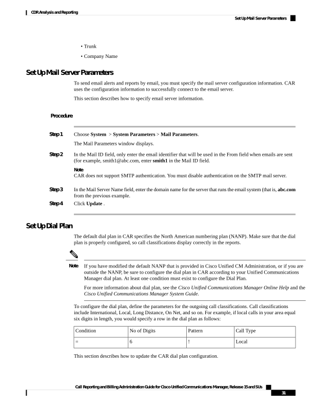
Page 44
Procedure
Step 1
Choose System > System Parameters > Dial Plan Configuration.
The Dial Plan Configuration window displays.
Step 2
In the Toll Free Numbers field, enter the numbers in your dial plan that can be placed without a charge.
Step 3
Update the values in the table by using the following fields:
a)
Condition - Select the condition of the rule where > represents greater than, < represents less than, and =
represents a value that is equal to the specified value in the No of Digits field.
b) No of Digits - Choose the number of digits in the directory number to which this rule should be applied.
If the number of digits does not impact the rule, specify NA.
c)
Pattern - Enter the pattern that is used for the call classification, where
• G - Signifies classified as specified in the rule (G equals a wildcard for the gateway area code that
is specified.
• K - Signifies classified as specified in the rule (K equals a wildcard for the trunk area code that is
specified).
• T - Retrieves the toll-free numbers that are configured in CAR.
• ! - Signifies multiple digits (any number that is more than 1 digit in length, such as 1234 or 5551234).
• X - Signifies a single-digit number (such as 0, 1, or 9).
d) Call Type - Choose the call type if the condition is satisfied.
Step 4
To add more rows, check the check box in the row below where you want to add rows and click Add Rows
link. The system adds a row above the row that you chose. To delete a row, check the check box by the row
that you want to delete and click Delete Rows.
Note
CAR classifies calls on the basis of the dialed number as stored in the CDRs. If the dialed digits differ from
the digits that are written in CDRs (due to number transformations), configure the Dial Plan in CAR on the
basis of how the digits show up in CDRs.
Step 5
Click Update.
Restore Default Values
If you have modified the default dial plan in CAR, you can restore the default values that are based on the
North American numbering plan (NANP).
The following table provides the default NANP values.
Table 7: Default Values for CAR Dial Plan
Call Type
Pattern
No of Digits
Condition
Row
OnNet
!
5
1
Call Reporting and Billing Administration Guide for Cisco Unified Communications Manager, Release 15 and SUs
32
CDR Analysis and Reporting
Restore Default Values
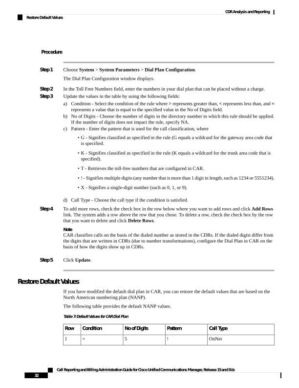
Page 45
Call Type
Pattern
No of Digits
Condition
Row
Local
!
7
2
Others
T!
10
3
Local
G!
10
4
Local
K!
10
5
Long Distance
!
10
6
Others
T!
11
7
Local
XG!
11
8
Local
XK!
11
9
Long Distance
!
11
10
International
011!
3
11
The following information explains the default table values.
• Row 1 - If the number of digits that are dialed equals 5 and the pattern is! (more than one digit, in this
case, 5 digits), the call gets classified as On Net.
• Row 2 - If the number of digits that are dialed equals 7 and the pattern is! (more than one digit, in this
case, 7 digits), the call gets classified as Local.
• Row 3 - If the number of digits that are dialed equals 10 and the pattern is T! (more than one digit, in
this case a 10-digit number that starts with a Toll Free number code), the call gets classified as Others.
• Row 4 - If the number of digits that are dialed equals 10 and the pattern is G! (more than one digit, in
this case a 10-digit number that starts with a gateway code), the call gets classified as Local.
• Row 5 - If the number of digits that are dialed equals 10 and the pattern is K! (more than one digit, in
this case a 10-digit number that starts with a trunk code), the call gets classified as Local.
• Row 6 - If the number of digits hat is that are dialed equals 10 and the pattern is! (more than one digit,
in this case a 10-digit number), the call gets classified as Long Distance.
• Row 7 - If the number of digits that are dialed equals 11 and the pattern is T! (more than one digit, in
this case an 11-digit number that starts with a toll-free number code), the call gets classified as Others.
• Row 8 - If the number of digits that are dialed equals 11 and the pattern is XG! (more than one digit, in
this case an 11-digit number that starts with any single digit followed by a gateway code), the call gets
classified as Local.
• Row 9 - If the number of digits that are dialed equals 11 and the pattern is XK! (more than one digit, in
this case an 11-digit number that starts with any single digit followed by a trunk code), the call gets
classified as Local.
• Row 10 - If the number of digits that are dialed equals 11 and the pattern is! (more than one digit, in this
case an 11-digit number), the call gets classified as Long Distance.
Call Reporting and Billing Administration Guide for Cisco Unified Communications Manager, Release 15 and SUs
33
CDR Analysis and Reporting
Restore Default Values
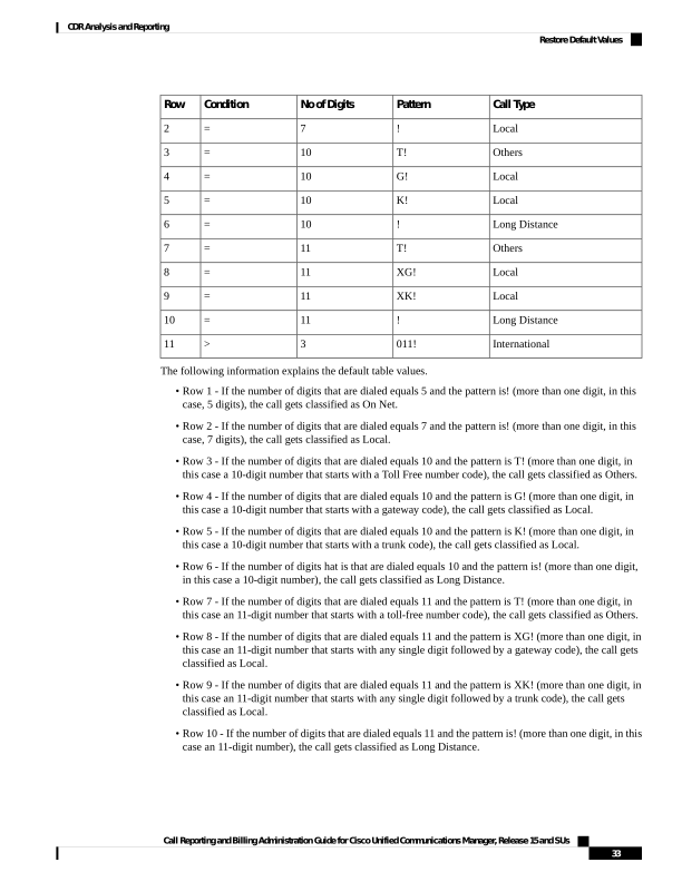
Page 46
• Row 11 - If the number of digits dialed is greater than 3 and starts with 011, the call gets classified as
International.
If none of the condition gets satisfied, the call gets classified as Others. This section describes how to restore
the NANP dial plan values in CAR.
The combination of characters, such as '!!', 'GG', 'KK', 'TT', 'GK', 'KG' is not allowed in dial plan configuration.
Note
Procedure
Step 1
Choose System > System Parameters > Dial Plan Configuration.
The Dial Plan Configuration window displays.
Step 2
Click Restore Defaults.
The restoration takes effect at midnight. To make changes take effect immediately, restart the Cisco CAR
Scheduler service.
Set Up Gateway
Configure the gateways in CAR for existing Unified Communications Manager system gateways. After you
add gateways to Cisco Unified CM Administration, configure the new gateways in CAR. When gateway is
deleted from the Unified Communications Manager system, the system automatically removes the gateways
(and any configuration settings that you specified) from CAR
Tip
CAR uses the area code information to determine whether calls are local or long distance. You must provide
the Number of Ports information for each gateway to enable CAR to generate the Utilization reports.
“G” acts as a wildcard for the gateway area codes that is used in a Dial Plan configuration.
Note
This section describes how to configure gateways in CAR.
Procedure
Step 1
Choose System > System Parameters > Gateway Configuration.
The Gateway Configuration window displays.
Note
If you have not configured gateways in Cisco Unified CM Administration, a message displays that indicates
that you have not configured gateways for the system.
Call Reporting and Billing Administration Guide for Cisco Unified Communications Manager, Release 15 and SUs
34
CDR Analysis and Reporting
Set Up Gateway


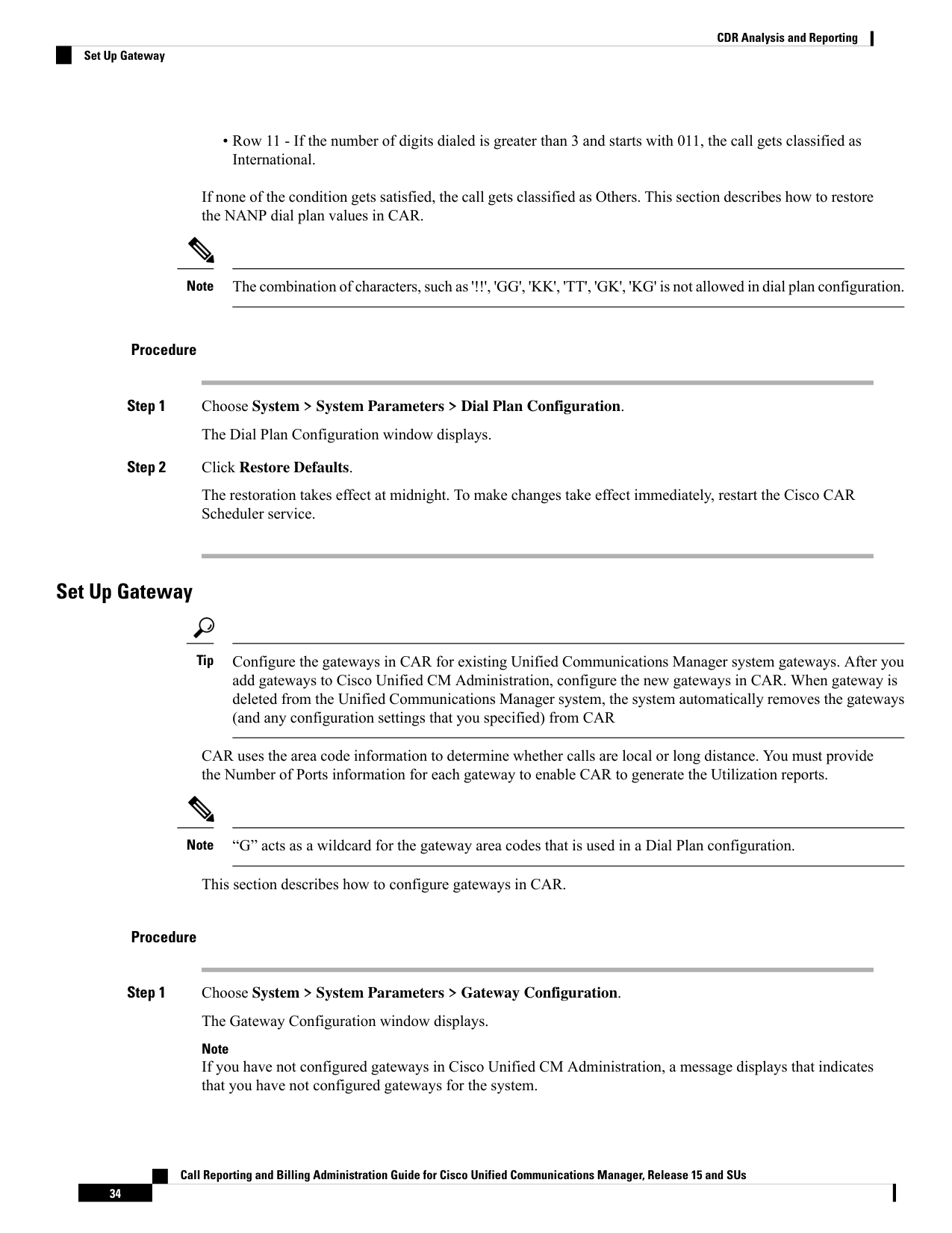
Page 47
Step 2
Perform one of the following tasks:
a)
To update the area code for all gateways, enter the area code in the Area Code field and click Set Area
Code .
A message displays that indicates that you must click Update to save changes. Click OK.
b) To update the area code for specific gateways, enter the area code for each gateway that you want to
configure in the area code field for that gateway.
Step 3
In the Max No. of Ports field, enter the number of ports for each gateway that you want to configure. The
maximum number of ports range goes from 1 to 999.
Note
CAR uses the values that were provided for the gateway when it was added in Cisco Unified CM
Administration. Therefore, some gateways will already have an area code setting or have a zero for maximum
number of ports, depending on the details that were specified when the gateway was added in Cisco Unified
CM Administration. CAR does not accept 0 as a value for the maximum number of ports; you may be prompted
to change the maximum number of ports for all gateways with a value of zero.
Step 4
Click Update.
You can run reports in CAR on any or all the configured gateways.
Set Up Trunk
Configure the trunks in CAR for existing Unified Communications Manager system trunks. After you add
trunks to Cisco Unified CM Administration, configure the new trunks in CAR. When trunks are deleted from
the Unified Communications Manager system, the system automatically removes the trunks (and any
configuration settings that you specified) from CAR.
Tip
CAR uses the area code information to determine whether calls are local or long distance. You must provide
the Number of Ports information for each trunk to enable CAR to generate the Utilization reports.
This section describes how to configure trunks in CAR.
Procedure
Step 1
Choose System > System Parameters > Trunk Configuration.
The Trunk Configuration window displays.
Note
If you have not configured trunks in Cisco Unified CM Administration, a message displays that indicates that
you have not configured trunks for the system.
Step 2
Perform one of the following tasks:
a)
To update the area code for all trunks, enter the area code in the Area Code field and click Set Area Code.
A message displays that indicates that you must click Update to save changes. Click OK.
Call Reporting and Billing Administration Guide for Cisco Unified Communications Manager, Release 15 and SUs
35
CDR Analysis and Reporting
Set Up Trunk

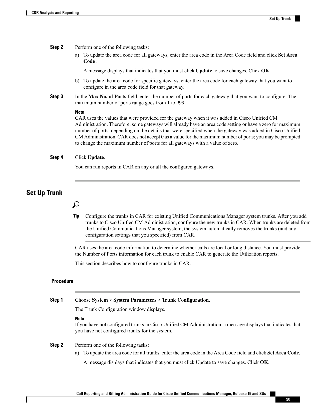
Page 48
b) To update the area code for specific trunks, enter the area code for each trunk that you want to configure
in the area code field for that trunk.
Step 3
In the Max No. of Ports field, enter the number of ports for each trunk that you want to configure. The
maximum number of ports range goes from 1 to 999.
Note
CAR uses the values that were provided for the trunk when it was added in Cisco Unified CM Administration.
Therefore, some trunks will already have a zero for maximum number of ports, depending on the details that
were specified when the trunk was added in Cisco Unified CM Administration. CAR does not accept zero as
a value for the maximum number of ports; you may be prompted to change the maximum number of ports
for all trunks with a value of zero.
Step 4
Click Update.
You can run reports in CAR on any or all the configured trunks.
Set Up System Preferences
CAR provides default system preferences; however, you can customize the system by specifying values for
the system parameters.
This section describes how to specify values for system preferences.
Procedure
Step 1
Choose System > System Parameters > System Preferences.
The System Preferences window displays. The list of available system parameters displays in the Parameter
Name list.
Step 2
In the Parameter Value field, enter the desired value for the parameter as described in the following table.
Table 8: System Preferences Parameter
Description
Parameter
Enter the company name that is used as header
information in reports. The company name cannot
exceed 64 characters in length.
COMPANY_NAME
Step 3
Click Update.
Set Up CDR Load Schedule
By default, CDR data loads continuously 24 hours a day, 7 days a week, and loads only CDR records.
Call Reporting and Billing Administration Guide for Cisco Unified Communications Manager, Release 15 and SUs
36
CDR Analysis and Reporting
Set Up System Preferences
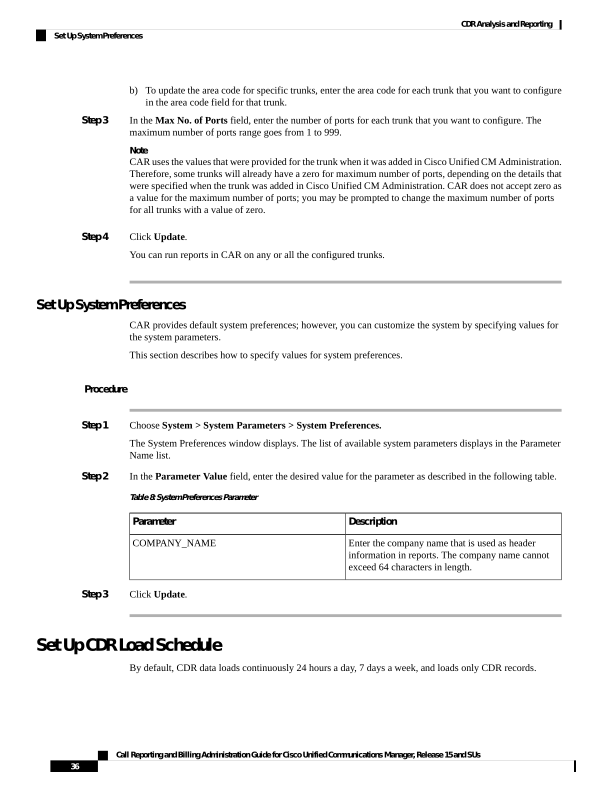
Page 49
The default batch size equals 600 CDR or CMR records. The default sleep time between each CDR batch
equals 2500 and 3000ms for each CMR batch. However you can, configure the batch size from the
tbl_system_preferences table “LOADER_BATCH” column to have any value 50-2000.
Note
This section describes how to customize the loading schedule, how to restore the default loading schedule if
it is customized, and how to disable CDR loading.
Disable CDR loading when you are installing or upgrading the system. The CDR data does not get updated
when CDR loading is disabled. Be sure to enable CDR loading again as soon as possible. The CAR tool does
not affect the CDR generation in Unified Communications Manager.
To manually delete the CAR data and reload the database with CDRs.
Tip
Procedure
Step 1
Choose System > Scheduler > CDR Load.
The CDR Load window displays.
Step 2
Choose one of the following options:
a)
Disable Loader - To disable CDR data loading, check the Disable Loader check box and click Update.
CDR data will not load into CAR until you enable CDR loading. Changes take effect at midnight. You
can force the change to take effect immediately by stopping and restarting the CAR Scheduler service.
To enable CDR data loading, uncheck the Disable Loader check box and continue with the next step to
configure the load parameters.
b) Continuous Loading 24/7 - To enable the CDR Loader to run continuously 24 hours a day, 7 days a week
to load CDRs into the CAR database, check the Continuous Loading 24/7 check box and click Update.
This choice represents the default setting for the CDR Load Scheduler.
Note
Under the default setting, only CDR records continuously load. The CMR records do not load. You must
manually uncheck the Load CDR only check box to force the CMR records to continuously load with
the CDR records.
The CAR Scheduler service stops, and the CAR Loader, as configured, runs immediately
(Within1-2minutes). The CAR Scheduler service restarts. If no new files for processing exist, the CDR
Loader sleeps and then checks periodically for new files to be loaded.
Note
If this option is chosen, it takes over precedence and ignores the other CDR and CMR load parameters
on the screen, such as Time, Loading Interval, Duration, and Uninhibited Loading.
c)
Load CDR Only - To load only CDR records into the CAR database, check the Load CDR only check
box and click Update. Continue to the next step to configure the load parameters. With this option, CMR
Call Reporting and Billing Administration Guide for Cisco Unified Communications Manager, Release 15 and SUs
37
CDR Analysis and Reporting
Set Up CDR Load Schedule


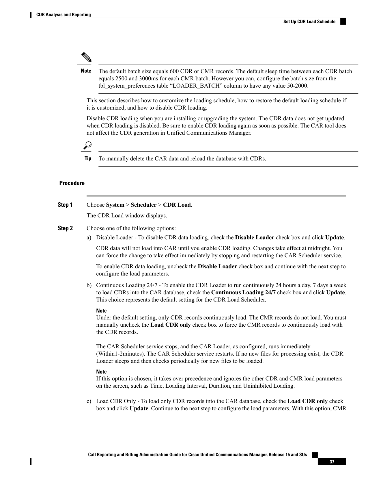
Page 50
records do not load into the CAR database. This choice represents the default setting for the CDR Load
Scheduler.
Step 3
In the Load CDR & CMR area, complete the fields as described in the following table.
Table 9: Load CDR and CMR Values
Value
Field
Choose the hour and minute that you want CAR to
begin loading CDR data from the CDR flat files.
Time
Choose the interval at which you want records that
are loaded. The interval can range from every 15
minutes to every 24 hours.
Loading Interval
Enter the number of minutes that you want to allow
CDR data to load. Depending on the size of the CDR
flat files, CAR performance may degrade when CDRs
load. You can limit the time that is allowed for
loading, but in doing so, the possibility exists that
only a portion of the CDR data will be loaded in the
time that you set. Be sure to reconcile the duration
limit that you place with the interval. For example, if
you load CDR data every 15 minutes, the duration of
loading cannot exceed 15 minutes.
Duration
Uninhibited loading allows you to set a time during which CDR data load continuously. CDR data does not
load automatically in the duration that is specified. The CDR data loads uninhibited in the specified duration
only if loading starts at the duration that is specified in the Load CDR and CMR area settings. If CDR data
loading starts at an uninhibited loading interval, loading continues to the end of the uninhibited loading interval,
plus the time in the duration field that is set in the Load CDR and CMR area, or until no new files to process
exist.
Uninhibited loading takes precedence over any values that are set for scheduled loading. If you do not want
uninhibited loading of CDR data, set the From and To values at 00:00.
Step 4
In the Uninhibited Loading of CDR area, complete the fields as described in the following table:
Table 10: Uninhibited Loading of CDR Values
Value
Field
Choose the hour and minute that you want continuous
loading of CDR data to begin.
From
Choose the hour and minute that you want continuous
loading of CDR data to end.
To
Step 5
Click Update.
CAR loads CDR data based on the time, interval, and duration that you have specified. Changes take effect
at midnight. You can force the change to take effect immediately by stopping and restarting the CAR Scheduler
service.
Call Reporting and Billing Administration Guide for Cisco Unified Communications Manager, Release 15 and SUs
38
CDR Analysis and Reporting
Set Up CDR Load Schedule
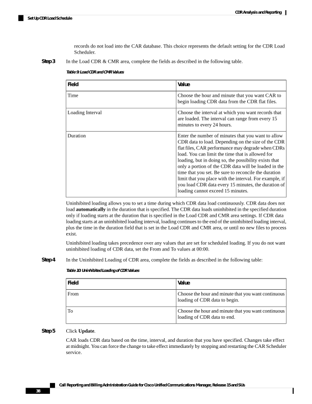
Page 51
Note
If Continuous Loading 24/7 is selected, the CAR Scheduler service restarts automatically when the Update
is clicked. CAR will load CDR data immediately (within 1-2 minutes).
Schedule Daily Reports
The Daily Report Scheduler schedules the time and duration of CAR daily reports.
Before you begin
Specify the reports to be generated by using the Automatic Generation/Alert Option.
This section describes how to schedule the time and duration of the automatic daily reports.
Procedure
Step 1
Choose System > Scheduler > Daily.
The Daily Scheduler window displays.
Step 2
From the Time drop-down list box, choose the hour and minute when you want daily reports to be generated.
A 24-hour clock represents time, where 0 equals midnight, and 1 through 11 represent a.m. hours, and 12
through 23 represent the p.m. hours of 1 p.m. through 11 p.m., respectively.
Step 3
From the Life drop-down list box, choose the duration of the report from the range of 0 to 12 days.
Tip
If you set the life of the report to 00, the report does not generate.
Step 4
Click Update.
Reports with report generation interval of Daily in the Automatic Generation/Alert Option and enabled
automatically generate every day at the time that you specify and get deleted after the number of days that
you specify.
Changes take effect at midnight. You can force the change to take effect immediately by stopping and restarting
the CAR Scheduler service.
Tip
To restore the defaults, click Restore Defaults. By default, the daily reports run at 1a.m. every day and get
purged after two days.
Schedule Weekly Reports
The Weekly Report Scheduler schedules the day, time, and duration of the automatic weekly reports.
Call Reporting and Billing Administration Guide for Cisco Unified Communications Manager, Release 15 and SUs
39
CDR Analysis and Reporting
Schedule Daily Reports
Page 52
Before you begin
Use the Automatic Generation/Alert Option to specify the reports to be generated.
This section describes how to schedule the day, time, and duration of the automatic weekly reports.
Procedure
Step 1
Choose System > Scheduler > Weekly.
The Weekly Scheduler window displays.
Step 2
From the Day of Week drop-down list box, choose the day that you want reports to be generated.
Step 3
From the Time drop-down list box, choose the hour and minute when you want reports to be generated.
A 24-hour clock represents time, where 0 equals midnight, and 1 through 11 represent a.m. hours, and 12
through 23 represent the p.m. hours of 1 p.m. through 11 p.m., respectively.
Step 4
From the Life drop-down list box, choose the duration of the report from the range of 00 to 12 weeks. The
option that you choose indicates how many weeks the report remains on the disk before the report gets deleted.
Tip
If you set the life of the report to 00, the report does not generate.
Step 5
Click Update.
Reports with report generation interval of Weekly in the Automatic Generation/Alert Option and enabled
automatically generate every week at the time that you specify and get deleted after the number of weeks that
you specify.
Changes take effect at midnight. For the changes to take effect immediately, stop and restart the CAR Scheduler
service in the Control Center - Feature Services window.
Tip
To restore the defaults, click Restore Defaults. By default, weekly reports run at 4 a.m. every Sunday and
get purged after four weeks.
Schedule Monthly Reports
The Monthly Report Scheduler schedules the day, time, and duration of CAR monthly reports.
Before you begin
Use the Automatic Generation/Alert Option to specify the reports to be generated.
This section describes how to schedule the day, time, and duration of the automatic monthly reports.
Procedure
Step 1
Choose System > Scheduler > Monthly.
Call Reporting and Billing Administration Guide for Cisco Unified Communications Manager, Release 15 and SUs
40
CDR Analysis and Reporting
Schedule Monthly Reports
Page 53
The Monthly Scheduler window displays.
Step 2
From the Day of Month drop-down list box in the Monthly Bill Generation row, choose the day of the month
on which you want the report to be generated.
If you set the value to a day that does not occur in a given month (such as 29, 30, or 31), the report generates
on the last day of that month.
Step 3
From the Time drop-down list box in the Monthly Bill Generation row, choose the hour and minute when
you want the report to be generated.
A 24-hour clock represents time, where 0 equals midnight, and 1 through 11 represent a.m. hours, and 12
through 23 represent the p.m. hours of 1 p.m. through 11 p.m., respectively.
Step 4
From the Life drop-down list box in the Monthly Bill Generation row, choose the duration of the report from
the range of 00 to 12 months. The option that you choose indicates how many months the report remains on
the disk before the report gets deleted.
Tip
If you set the life of the report to 00, the report does not generate.
Step 5
From the Day of Month drop-down list box in the Other Monthly Reports row, choose the day of the month
on which you want the reports to be generated.
If you set this value to a day that does not occur in a given month (such as 29, 30, or 31), the report generates
on the last day of that month.
Step 6
From the Time drop-down list box in the Other Monthly Reports row, choose the hour and minute that you
want reports to be generated.
A 24-hour clock represents time, where 0 equals midnight, and 1 through 11 represent a.m. hours, and 12
through 23 represent the p.m. hours of 1 p.m. through 11 p.m., respectively.
Step 7
From the Life drop-down list box in the Other Monthly Reports row, choose the life of the report from the
range of 00 to 12 months. The option that you choose indicates how many months the report remains on the
disk before the report gets deleted.
Tip
If you set the life of the report to 00, the report does not generate.
Step 8
Click Update.
Reports with report generation interval of Monthly in Automatic Generation/Alert Option and enabled
automatically generate every month at the time that you specify and are deleted after the number of months
that you specify.
Changes take effect at midnight. For the changes to take effect immediately, stop and restart the CAR Scheduler
service in the Control Center - Feature Services window.
Tip
To restore the defaults, click Restore Defaults. By default, monthly bill reports run at 3 a.m. on the first day
of every month and get purged after two months, and other monthly reports run at 2 a.m. on the first day of
every month and get purged after two months.
Call Reporting and Billing Administration Guide for Cisco Unified Communications Manager, Release 15 and SUs
41
CDR Analysis and Reporting
Schedule Monthly Reports
Page 54
Alarms
This release of Unified Communications Manager introduces a CAR alarm catalog (CARAlarmCatalog.xml)
for the CAR Scheduler.
The following table displays the alarms/alerts in this catalog.
To configure these alarms, go to Cisco Unified Serviceability > Alarm > Configuration > CDR Services.
Table 11: CAR Alarm Catalog
Description
Severity
Name
A critical CAR scheduled job failed. An alert
gets raised when critical CDR Scheduler jobs
and tasks fail (for example, DailyCdrLoad,
PopulateSchedules, etc.).
ERROR_ALARM
CARSchedulerJobFailed
A CAR scheduled job failed. An alarm gets
sent for all other noncritical CAR Scheduler
jobs and tasks (for example, daily, weekly,
and monthly reports, QoSNotification,
ChargeLimitNotification, etc.).
ERROR_ALARM
CARSchedulerJobError
Bad CDR or CMR flat file was found during
CDR Load to the CAR database. The CDR
Loader can detect bad or corrupted CDR
and/or CMR flat files and log the specified
error. Information on the failure cause
(specified reason for the bad record) and the
failure summary (tracks number of bad records
in comparison to the total records in the file)
gets provided.
ERROR_ALARM
BadCDRFileFound
Indicates debug events from CAR IDS
database engine. This alarm provides
low-level debugging information from CAR
IDS database engine. System administrator
can disregard this alarm.
DEBUG_ALARM
CARIDSEngineDebug
No error has occurred but some routine event
has completed in CAR IDS database engine.
INFORMATION_ALARM
CARIDSEngineInformation
This alarm does not compromise data or
prevent the use of the system but requires
monitoring by the CAR DB adminstrator.
CRITICAL_ALARM
CARIDSEngineCritical
Combined alarm for emergency and error
situations. This alarm indicates that something
unexpected occurred that can compromise
data, or access to data, or cause CAR IDS to
fail.
ERROR_ALARM
CARIDSEngineFailure
Call Reporting and Billing Administration Guide for Cisco Unified Communications Manager, Release 15 and SUs
42
CDR Analysis and Reporting
Alarms
Page 55
For additional information on these alarms and recommended action, see the alarm definitions at Cisco Unified
Serviceability > Alarm > Definitions > CARAlarmCatalog.
CAR System Database
You can configure CAR to notify you when the CAR database size exceeds a percentage of the maximum
number of records. You can set the message and the maximum number of records and specify the alert
percentage.
You can configure the system to maintain the CAR database size between the low water mark and the high
water mark values that you configure through the Configure Automatic Database Purge window. When the
database size reaches the low water mark, CAR sends an alert to the user. When the database size reaches the
high water mark, the system deletes records based on the deletion age and sends an e-mail.
To configure the CAR system database, go to Cisco Unified Serviceability > Tools > CDR Analysis and
Reporting > System or Report Config.
Purge CAR Database
This section describes how to manually purge selected records from the CAR database and how to delete all
of the CAR data and reload the database with new CDR data. You may want to reload the database to reclassify
calls after dial-plan updates, user-device association changes, call rate changes, and so on.
Before you begin to manually purge data, disable the CDR Loader.
1.
Choose System > Scheduler > CDR Load.
2.
Chosse either of the following:
• Disable Loader - check the Disable Loader check box and click the Update.
Enable CDR loading to load the data into CAR. Changes take effect at midnight. You can force the
change to take effect immediately by stopping and restarting the CAR Scheduler service.
• Enable Loader - uncheck the Disable Loader check box.
Manual purging of the CDRs gets stopped if the CAR Web Service is stopped during the manual purge process.
Manual purging cannot begin again until the CAR Web Service restarts. Then you must begin the manual
purge process again.
There are two ways to intentionally stop the CAR Web Service:
• Deactivate the CAR Web Service in the Serviceability Service Activation window (Cisco Unified
Serviceability > Service Activation).
• Stop the CAR Web Service in the Feature Services window of the Serviceability Control Center (Cisco
Unified Serviceability > Tools > Control Center - Feature Services).
The CDR Loader cannot begin again until either the CAR Web Service or the CAR Scheduler gets restarted.
A CAR administrator can no longer generate CAR reports when a manual purge of the CAR database is in
process or CDR records are reloading. The following error message displays when you try to run reports
during these processes:
10023: Manual Purge/Reload is in process. Please run the reports once the Manual
Purge/Reload is over.
Call Reporting and Billing Administration Guide for Cisco Unified Communications Manager, Release 15 and SUs
43
CDR Analysis and Reporting
CAR System Database
Page 56
Both the Purge button and the Reload All Call Detail Records button get disabled, and the following alert
message displays on the Manual Purge window, when either a manual purge or CDR reload occurs:
Manual Purge/Reload is still running. User will not be allowed to run another
instance of Manual Purge/Reload. So, both Purge and Reload All Call Detail Records
buttons are disabled.
Procedure
Step 1
Choose System > Database > Manual Purge.
The Manual Database Purge window displays.
Step 2
Choose one of the following actions:
a)
To delete the existing CAR data and reload the CAR database, click Reload All Call Detail Records.
The system displays a message that indicates that deleting the records may impact system performance.
To continue the reload process, click OK.
The system begins loading the CDRs into the CAR database within 5 minutes and continues uninterrupted
for up to 6 hours. To monitor the progress of the reload, generate the CDR Load event log.
After the system loads the new records, the system loads the records according to the schedule that is
configured. By default, CDR data loads 24 hours per day and 7 days per week.
b) To manually purge selected CAR records, continue with the next step.
Step 3
In the Select Table field, choose the table in the database that you want purged.
To view the tables for which manual purge is permitted, the total number of records in the table, and the latest
record and oldest record in the table, click Table Information.
The Table Information window displays. You will see a table with the following information:
Oldest Record
Latest Record
Total No. of Records
Table Name
Database Name
0
0
0
Tbl_billing_data
CAR
0
0
0
Tbl_billing_error
CAR
0
0
0
Tbl_purge_history
CAR
To return to the Manual Database Purge window, click Close.
Step 4
In the Delete records field, choose a date that will determine which records will be purged by clicking one of
the following radio buttons:
a)
Older than - Choose a date for which all records before that date will be deleted.
b) Between - Choose a range of dates between which all records will be deleted.
Step 5
Choose the date range of the CAR records that you want to delete.
Step 6
To delete all records older than or between the dates that you specified, click Purge.
A prompt advises you that you are about to permanently delete the specified records.
Step 7
To purge the records, click OK or click Cancel to abort the purge operation.
Call Reporting and Billing Administration Guide for Cisco Unified Communications Manager, Release 15 and SUs
44
CDR Analysis and Reporting
Purge CAR Database
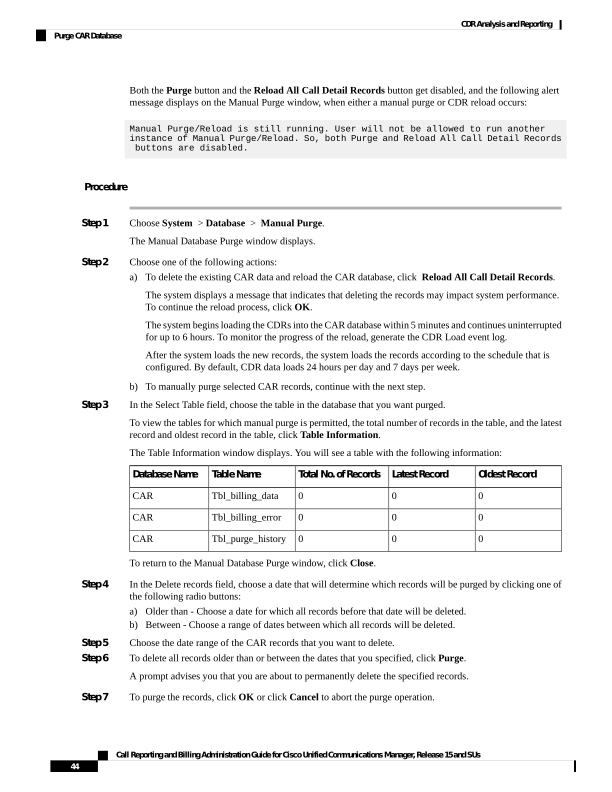
Page 57
If you click OK, the records get purged from the selected table. After successful deletion of records, the status
message shows the number of records that were deleted from the table.
Set Up Automatic Database Purge
This section describes how to schedule and disable automatic purging of the CAR database. By default, the
system enables automatic database purge.
Procedure
Step 1
Choose System > Database > Configure Automatic Purge.
The Configure Automatic Database Purge window displays. At the top of the window, the percentage amount
of the CAR database space that has been used gets displayed. The maximum CAR Database space that is
available gets displayed in megabytes.
Step 2
From the Low Water Mark drop-down list box, choose the minimum percentage of the maximum CAR
database size that you want the system to use for CAR data. The default value specifies 80percent.
Tip
The system notifies you when the CAR database size reaches the low or the high water mark; it also notifies
you when the CAR database size exceeds the maximum number of records. For information on configuring
an e-mail alert.
Step 3
From the High Water Mark drop-down list box, choose the maximum percentage of the maximum CAR
database size that you want the system to use for CAR data. The default value specifies 90percent.
Step 4
In the Max Age of Call Detail Records field, enter the maximum number of days that you want to keep the
CDRs in the CAR database. Enter a number between 1 and 180. The default value specifies 60days.
CAR deletes all CDRs that are older than the specified number of days.
Note
To restore the default values for the fields in this window, click Restore Defaults.
Step 5
Click Update.
The changes take effect at midnight. To make changes take effect immediately, restart the Cisco CAR Scheduler
service.
Note
When the 2M or HWM limit is breached:
a.
CAR deletes the database partitions one by one, starting from the oldest date partition.
b.
CAR stops purging under one of the following conditions:
• When the record count falls below the 2M or HWM limit.
• When there is only last two days partitions left on the billing tables.
Call Reporting and Billing Administration Guide for Cisco Unified Communications Manager, Release 15 and SUs
45
CDR Analysis and Reporting
Set Up Automatic Database Purge
Page 58
In cases where there are large number of CDRs present in the billing tables and deleting the partitions does
not bring the record count below the 2M or HWM limit, CAR holds at least two days data in the database.
When the record count in the database reaches the 2M or HWM limit:
a.
CAR loader stops processing the new records.
b.
CAR starts purging the records from the oldest partition till the record count reaches 2M or HWM limit.
If the record count does not fall below the 2M or HWM limit even after deleting the records, CAR holds at
least two days records and stops the CAR loader. Also, CAR sends an e-mail notification to CAR administrator
to proceed with manual purge.
Following an upgrade, the Configure Automatic Database Purge > MAX DATABASE AGE parameter
will be changed to one of the following:
• If the MAX DATABASE AGE in the old version is between 1 and 60, it will be configured to 60 in the
new version.
• If the MAX DATABASE AGE in the old version is between 60 and 180, it will be configured to the
same age in the new version.
• If the MAX DATABASE AGE in the old version is more than 180, it will be configured to 180 in the
new version.
CAR System Event Log
CAR provides logs that you can use to track the status of the various activities. The event log tracks events
that the CAR Scheduler triggers, such as automatically generated reports, loading of CDRs, report deletions,
and database purging.
The event log provides a report on the status of the activities that the CAR Scheduler controls. The event log
report shows whether the tasks started, completed successfully, or are in progress.
Generate Event Log
This section describes how to generate the event log report. The event log includes a list of tasks/reports that
are scheduled on a daily, weekly, or monthly basis.
This release of Unified Communications Manager introduces the Task Monitor and Database Maintenance
as new features.
TaskMonitor monitors the status of other jobs and cleans up Informix Dynamic Server (IDS) memory when
necessary by using the IDS command “onmode -F.” DatabaseMaintenance runs the IDS-recommended
optimized database maintenance “update statistics” procedures.
Task Monitor begins about 1minute after the Scheduler starts, and 1minute after the Scheduler repopulates
the schedules every day at midnight (00.00). The Task Monitor periodically (every 5minutes) monitors the
status of all jobs for the day from the tbl_event_log with the exception of the following jobs: PopulateSchedules,
TaskMonitor, DatabaseMaintenance, and DailyCdrLoad.
When a task does not start on schedule because a previous task is still running, you may see something like
the following trace message:
Call Reporting and Billing Administration Guide for Cisco Unified Communications Manager, Release 15 and SUs
46
CDR Analysis and Reporting
CAR System Event Log
Page 59
2008-02-14 08:00:04, 602 WARN [main] services. Scheduler - runTasks(): Job
[DailyCdrLoad] thread is busy, hence it will be removed from today’s schedule and
not be started!”
The Scheduler gives a grace period to periodically sleep for 10seconds and then check whether the task thread
is complete. The Scheduler sleeps up to 2 minutes total. If the task thread is not complete after the 2minutes
of wait, the next task gets removed from the current schedule, and does not run until its next scheduled time.
The following table displays the list of tasks/reports and how often they are scheduled.
Table 12: Task List
Scheduled
Task
Daily
CDR Load
Daily
Task Monitor1
Daily
Database Maintenance2
Daily
QoS Notification
Daily
Charge Limit Notification
Daily
Database Alert
Daily
Delete Reports
Daily
Database Purge
Daily
Traffic Summary - Hour of Day
Daily
Top N Charge
Daily
Top N Duration
Daily
Top N Calls
Daily
Conference - Detail
Weekly
Traffic Summary - Day of week
Weekly
Conference Bridge Utilization - Day of week
Weekly
Voice Messaging Utilization - Day of week
Weekly
Route Pattern/Hunt Pilot Utilization - Day of week
Weekly
Route/Hunt List Utilization - Day of week
Weekly
Route Group Utilization - Day of week
Weekly
Gateway Utilization - Day of week
Weekly
Line Group Utilization - Day of week
Monthly
QoS Summary
Call Reporting and Billing Administration Guide for Cisco Unified Communications Manager, Release 15 and SUs
47
CDR Analysis and Reporting
Generate Event Log
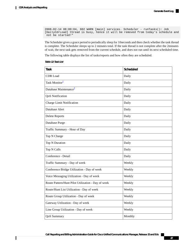
Page 60
Scheduled
Task
Monthly
Gateway Summary
Monthly
Traffic Summary - Day of month
Monthly
System Overview
Monthly
Department Bill Summary
Monthly
Individual Bill Summary
Monthly
Top N Charge
Monthly
Top N Duration
Monthly
Top N Calls
Monthly
Conference - Summary
1
2
34
Procedure
Step 1
Choose System > Log Screens > Event Log.
The Event Log window displays.
Step 2
Click the Daily radio button to choose daily jobs, the Weekly radio button to choose weekly jobs, or the
Monthly radio button to choose monthly jobs.
Step 3
In the List of Jobs area, choose the tasks for which you want information.
Step 4
To add the chosen task to the Selected Jobs area, click the right arrow icon.
Step 5
To remove tasks from the Selected Jobs area, choose the task that you want removed and click the left arrow
icon.
Step 6
To add tasks with a different frequency, repeat the previous steps. For example, you can have daily reports
and reports that include monthly or weekly tasks.
Step 7
Choose the status to include in the report. You must choose at least one status as described in the following
table.
Note
The system chooses the status of each event log report by default.
3 The system automatically configures and executes the Task Monitor, which is an internal task, on a daily basis.
4 Database Maintenance represents an internal task that the system automatically configures and executes on a daily basis.
Call Reporting and Billing Administration Guide for Cisco Unified Communications Manager, Release 15 and SUs
48
CDR Analysis and Reporting
Generate Event Log
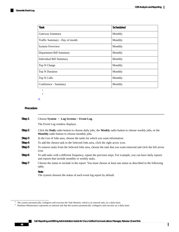
Page 61
Table 13: Event Log Report Status
Description
Status
If this check box is checked, the event log report
includes tasks that are complete.
Complete
If this check box is checked, the event log report
includes tasks that are currently in progress.
In Progress
If this check box is checked, the event log includes
tasks that have been interrupted, either manually by
an administrator, or by an administrative process such
as a DRS backup.
Interrupted
If this check box is checked, the event log report
includes tasks that have failed.
Unsuccessful
If this check box is checked, the event log report
includes tasks that have been scheduled but have not
yet started.
Scheduled
Note
When the Scheduler restarts, all unfinished jobs with a status of Scheduled get deleted. Current jobs with the
status of In Progress or Scheduled get changed to Interrupted.
Step 8
Choose a date range by choosing From and To values.
Step 9
To generate the event log report, click OK .
The event log displays information about the chosen tasks.
Step 10
Print the log by right-clicking on the screen and choosing Print.
Note
A grace period of up to 2 minutes gets provided, so an in-process job can finish before the next schedule job
is scheduled to begin.
Output of Event Log Report
Table 14: Event Log Report Output
Description
Parameter
Serial number
Sl No
Name of the task
Jobs
Time the task starts
Start Time
Time the task ends
End Time
Unsuccessful, in progress, completed
Status
Call Reporting and Billing Administration Guide for Cisco Unified Communications Manager, Release 15 and SUs
49
CDR Analysis and Reporting
Output of Event Log Report
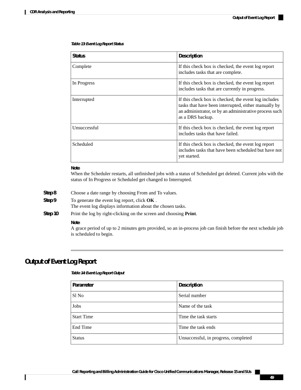
Page 62
Description
Parameter
Date the task is scheduled
Date
CAR Reports Configuration
Before you start generating reports with CAR, configure items such as the rating engine, QoS values, automatic
report generation and notification limits.
Rating Engine
You can use CAR to set a base monetary rate for the cost of calls based on a time increment. You can further
qualify the cost by applying the time-of-day and voice-quality factors. Service providers who must account
for service to subscribers commonly use this feature. Some organizations also use this information to establish
billing costs for users and departments in the organization for accounting or budgeting purposes.
Reports that use these rating parameters include Individual Bill, Department Bill, Top N by Charge, TopN
by Duration, and Top N by Number of Calls.
If you do not change the default value for charge base/block, the cost will always equal zero because the
default base charge per block equals zero.
Note
The charge of any call comprises the multiplication of the basic charge of the call, multiplication factor for
time of day, and multiplication factor for voice quality. You can set the basic charge for a call through the
Report Config > Rating Engine > Duration window. See the following list:
• Basic charge = cost, or number of units, applied to the duration block that is specified in the Number of
Blocks section.
• Number of blocks = total duration of call, in seconds, for which you want the base charge to be applied.
You can set the multiplication factor for time of day through the Report Config > Rating Engine > Time
of Day window. The basis of the settings provides the connect time of the call.
You can set the multiplication factor for voice quality through the Report Config > Rating Engine > Voice
Quality window.
QoS Values
CAR generates QoS reports. To qualify the data that is presented in those reports, CAR uses predefined values
that are set about voice quality. You can specify the value ranges that are good, acceptable, fair, and poor for
jitter, latency, and lost packets.
Automatic Generation of Reports and Alerts
CAR automatically generates reports based on a schedule. Report generation can include a daily, weekly, or
monthly summary report, QoS reports, traffic reports, Device/Route Plan utilization reports, and so on, that
you may want to view on a regular basis.
Call Reporting and Billing Administration Guide for Cisco Unified Communications Manager, Release 15 and SUs
50
CDR Analysis and Reporting
CAR Reports Configuration

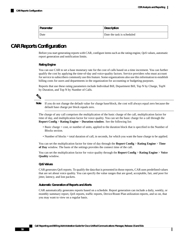
Page 63
Notification Limits
You can specify limits for QoS and daily charges, so the administrator gets alerted by e-mail when these limits
are exceeded. The alerts go to all users that are designated as CAR Administrators through Cisco Unified CM
Administration.
CAR Rating Engine
Use the CAR rating engine configuration to define the base rate and duration, time of day, and voice quality
rating parameters for calls.
Rating parameters for calls get used during CAR loading. If you want old CDR records in the CAR database
to use new values for these parameters, you must reload all the CDRs in the CAR database.
Note
Set Base Rate
To establish a cost basis for calls, you must specify a base rate for all calls. For example, if your service
provider charges you 6 cents for each minute, billed in 10-second increments, you can set the base rate at
which all calls are charged at 1cent for each 10-second increment.
This section describes how to establish the base charge and duration values.
If you use the default base charge value, reports do not provide any costs. The system provides default values,
but if left to the defaults, the Rating Engine stays disabled and does not provide costs.
Note
Procedure
Step 1
Choose Report Config > Rating Engine > Duration.
The Call Duration window displays.
Step 2
In the To (seconds) field, enter the seconds for which you want the base charge to be applied. For example,
if you are billed in 6-second increments, enter 6 in this field. If you are billed a flat rate for each minute
regardless of call duration, enter 60 in this field, so the charge is based on whole minutes.
Step 3
In the Base Charge/Block field, enter the cost basis for the seconds that are shown in the To (seconds) field.
For example, if you are billed 6 cents for each minute in 6-second increments, enter 0.006 in this field. If you
are billed 7 cents for each minute in whole minutes (no incremental billing), enter 0.07 in this field.
In the preceding examples, if you are billed in 6-second increments and the cost is 0.006 for each 6-second
increment, a call that lasts 7 seconds would cost 0.012. Rationale: Each 6-second increment costs 0.006, and
two blocks from 0–6 seconds occurred.
Likewise, if you are billed in whole minutes and the cost is 7 cents for each minute, a call that lasted 3 minutes
would cost 21 cents. Rationale: Each 60-second increment costs 7 cents, and three blocks of 1 minute occurred.
Step 4
Click Update.
Tip
Call Reporting and Billing Administration Guide for Cisco Unified Communications Manager, Release 15 and SUs
51
CDR Analysis and Reporting
CAR Rating Engine

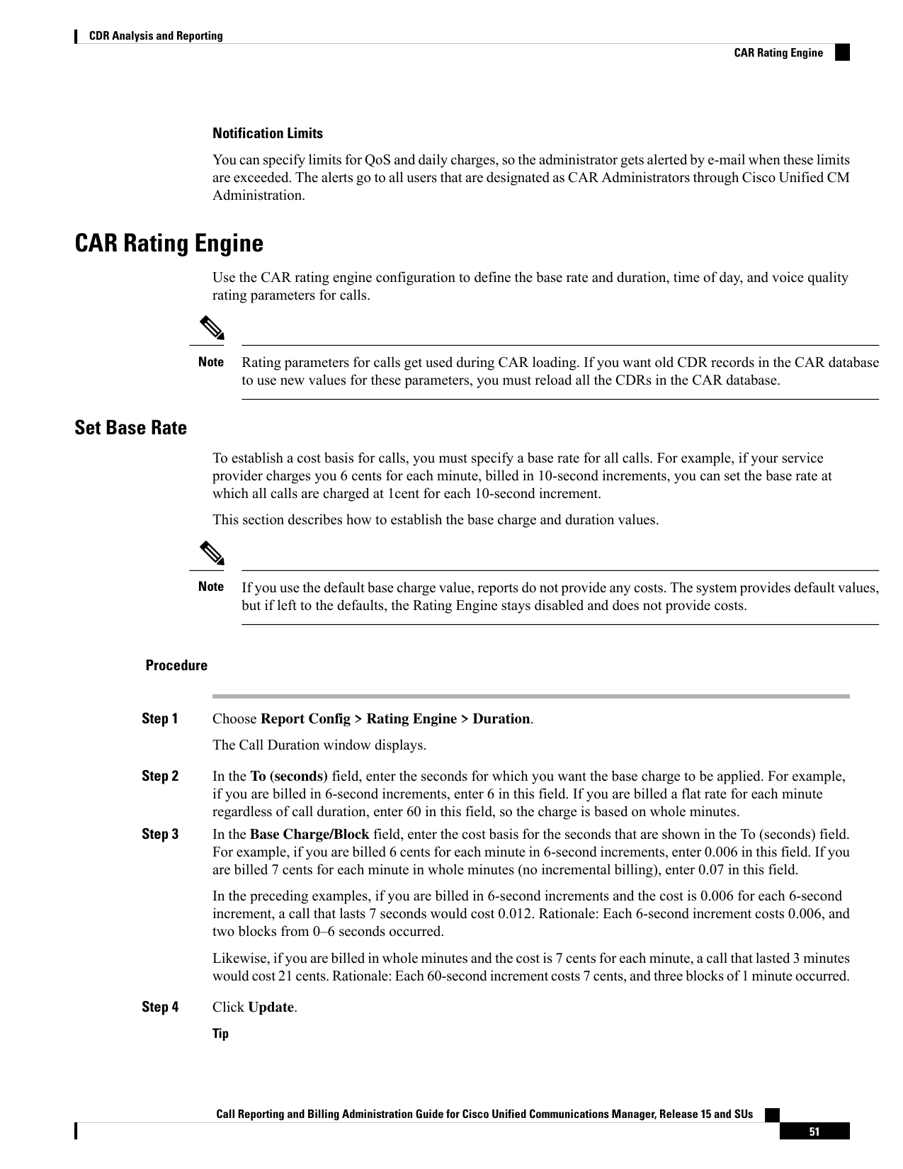
Page 64
To restore the default setting, click Restore Defaults. By restoring the default value of 0 for the call
charge/block, you effectively disable the other factors that are used in determining call cost.
Factor Time of Day
To further define the cost of calls, you can specify a multiplication factor for certain times of day. For example,
if you want to charge subscribers a premium for daytime calls, you can apply a multiplication factor to the
base charge/block that you specified in the Call Duration window.
This section describes how to establish certain times of day when calls cost more.
If you do not want to increase call cost by time of day, you can use the default values. The default multiplication
factor specifies 1, so no increase in call cost for time of day occurs.
Note
Procedure
Step 1
Choose Report Config > Rating Engine > Time of Day.
The Time of Day window displays.
Step 2
To add rows, click the Add Rows link.
The system adds a row between 00:00:00 and 23:59:59.
Step 3
To add additional rows, check the check box for the row above which you want to add a new row and click
the Add Rows link.
Note
To delete rows, check the check box for the row that you want to delete and click the Delete Rows link.
Step 4
Enter the From and To time ranges in 24-hour, minute, and second format. A 24-hour period, from 00:00:00
to 23:59:59, represents the default time range. If you want to set one time-of-day range from 8am to 5 pm,
you will need to establish three time-of-day ranges: the first from 00:00:00 to 07:59:59, the second from
08:00:00 to 16:59:59, and the third from 17:00:00 to 23:59:59.
Note
You must use Coordinated Universal Time (UTC), rather than a 12-hour clock, when factoring Time of Day
into Call Cost.
Step 5
Enter the Multiplication Factor that designates a number by which you want the base charge/block to be
multiplied when a call occurs in the specified time range. For example, if you charge a premium of double
the price for calls that are placed between 8a.m. and 5p.m., the multiplication factor equals 2.00. A multiplication
factor of 1.00 does not affect the cost of the call.
Step 6
To add the time-of-day and multiplication factors, click Update .
Tip
Call Reporting and Billing Administration Guide for Cisco Unified Communications Manager, Release 15 and SUs
52
CDR Analysis and Reporting
Factor Time of Day

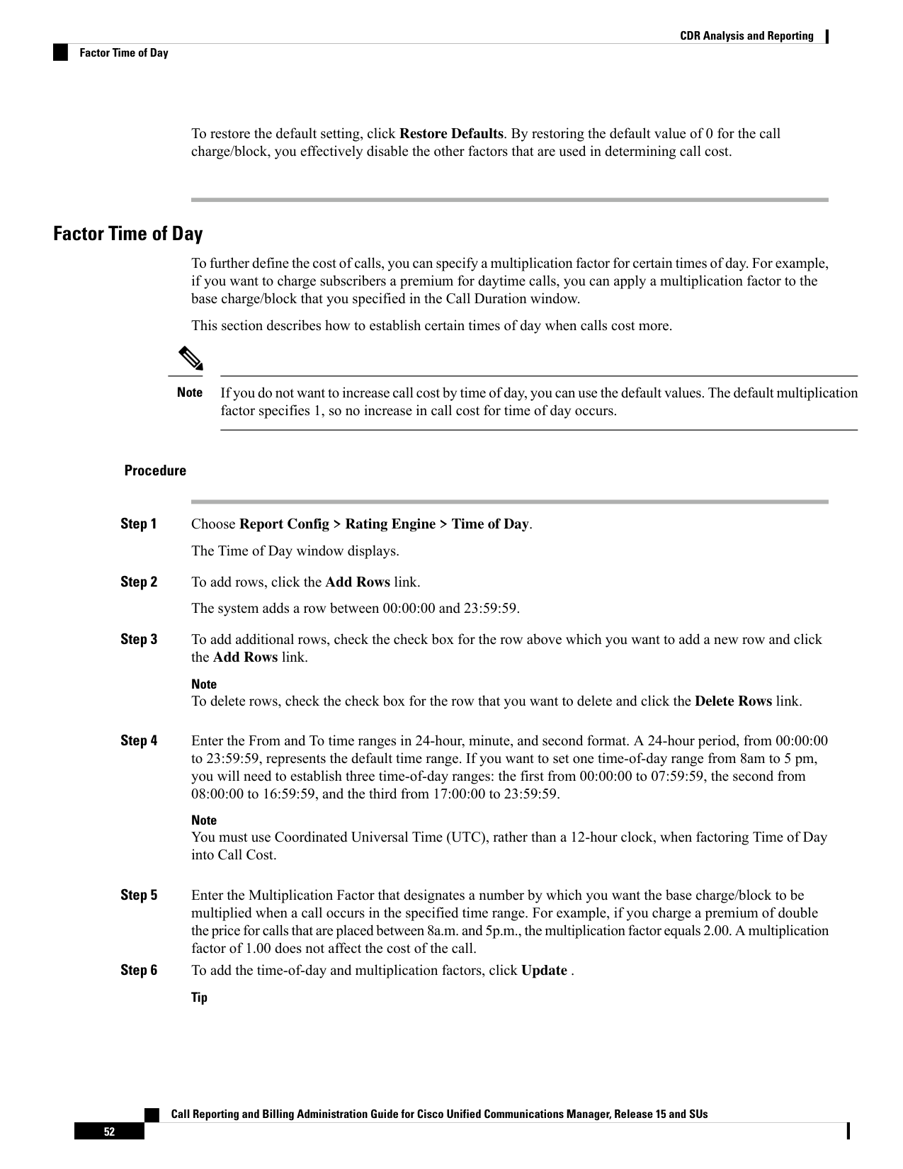
Page 65
To restore the default setting, click Restore Defaults.
Factor Voice Quality
To further define the cost of calls, you can specify a multiplication factor for the voice quality of a call. For
example, if subscribers are paying a premium price to ensure the highest voice quality on calls, you can apply
various multiplication factors to the base charge/block that you specified in the Call Duration window depending
on the voice quality. Using a multiplication factor other than 1.00 helps differentiate between the various
voice qualities calls as well.
This section describes how to establish call cost when calls that have a certain voice quality cost more.
If you do not want to increase, call cost by voice quality, you can use the default values. The default
multiplication factor equals 1.00, so no increase in call cost occurs for voice quality.
Note
Procedure
Step 1
Choose Report Config > Rating Engine > Voice Quality.
The Voice Quality window displays.
Step 2
In the Multiplication Factor field, enter the number by which you want the base charge/block to be multiplied
when a call occurs in the specified voice-quality category. The 'Define QoS values' section defines the
voice-quality categories: Good, Acceptable, Fair, and Poor.
Example
Voice Quality Good; Factor 1.2
Voice Quality Acceptable; Factor 1.0
Voice Quality Fair; Factor 1.0
Voice Quality Poor; Factor 0.8
A good call gets charged 1.2 times that of an acceptable or fair call. A poor call gets charged 0.8 times that
of an acceptable or fair call.
Note
Multiplication factor for a good call >= the multiplication factor for acceptable >= multiplication factor for
fair >= multiplication factor for poor.
Step 3
Cick Update .
Tip
To restore the default setting, click Restore Defaults.
Call Reporting and Billing Administration Guide for Cisco Unified Communications Manager, Release 15 and SUs
53
CDR Analysis and Reporting
Factor Voice Quality

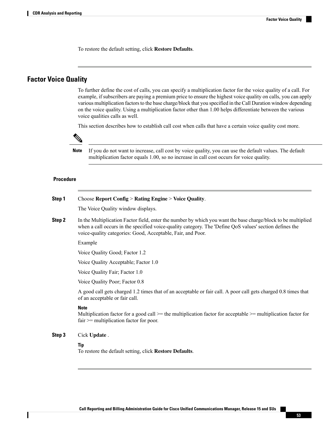
Page 66
Define QoS Values
QoS values get configured for lost packets, jitter, and latency based on good, acceptable, fair, or poor criteria.
If a call does not satisfy any of the criteria that are set for any of the four voice-quality categories, it receives
a classification of NA (not applicable); likewise, if the system is not configured to generate CMR data (or if
the CMR is bad), the CMR receives a classification of NA (not applicable).
Enter NA to ignore the values of a parameter. For example, a QoS parameter such as jitter, has NA, and the
QoS is defined as good, which means that the QoS depends only on the values of latency and lost packets.
All three parameters cannot have NA as values. Infinity designates the maximum value that is available for
any parameter. If you specify a rule where a jitter value from 500 to Infinity is considered poor, a call with
jitter greater than 500 receives a classification of poor.
Be aware that the classifications of “NA” and “Infinity” are case-sensitive.
Note
This section describes how to define the QoS values.
Procedure
Step 1
Choose Report Config > Define QoS.
The Define Quality of Service window displays. The following table describes the QoS default values.
Table 15: QoS Default Values
Default
QoS Parameter
Good - 0.00 to 15.00Acceptable - 15.01 to 30.00Fair
- 30.01 to 45.00Poor - 45.01 to infinity
Lost Packets
Good - 0 to 20Acceptable - 21 to 100Fair - 101 to
150Poor - 151 to infinity
Jitter
No default values apply.
Latency
Step 2
To add rows, check the check box for the row above which you want to add a new row and click Add Rows
link.
The new row gets added above the row that you checked, and the check box is cleared.
The rows represent the values that CAR uses to quantify the conditions good, acceptable, fair, and poor in
the QoS reports. For each value set, enter the upper and lower limits in the From and To columns.
Note
To delete rows, check the check box for the row that you want to delete and click Delete Rows link.
Step 3
For each value that you have set, choose the Quality of Service.
Step 4
Click Update.
Tip
Call Reporting and Billing Administration Guide for Cisco Unified Communications Manager, Release 15 and SUs
54
CDR Analysis and Reporting
Define QoS Values

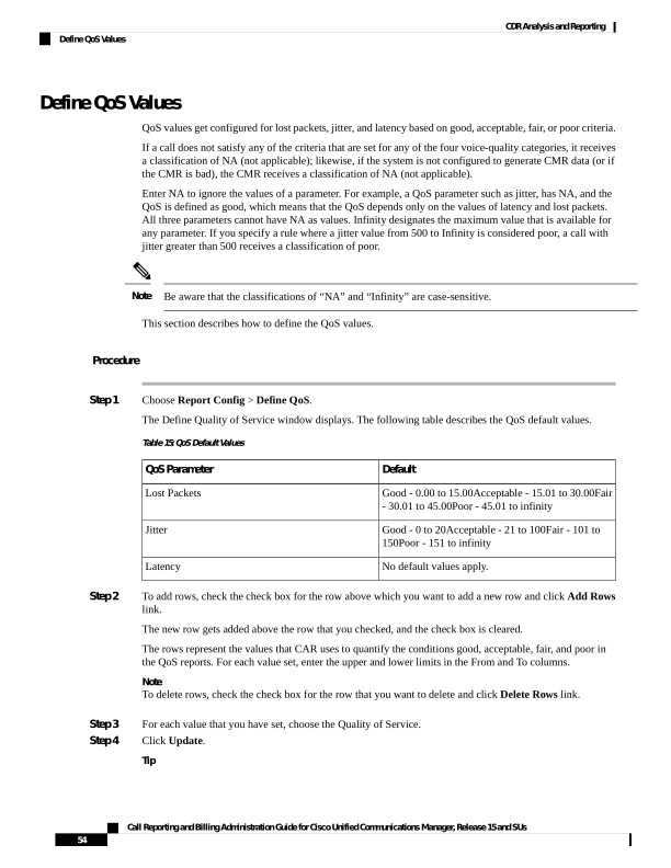
Page 67
To restore the default QoS values, click Restore Defaults.
Automatic Generation of CAR Reports and Alerts
Before You Begin
Before you start generating reports with CAR, configure the system.
The following table displays the list of reports that the system enables or disables for automatic generation,
the report generation interval, and the recipients of the report.
Table 16: Automatically Generated Reports
Recipients
Report Generation Interval
Name of Report
• CAR managers
• CAR administrators
Monthly
Department Bill Summary
• CAR administrators
Monthly
Gateway Summary
• Individual users
configured in Cisco
Unified CM.
• CAR administrators
Note
Administration users do
not get access to this
report.
Monthly
Individual Bill
• Individual users
configured in Cisco
Unified CM
• CAR managers
• CAR administrators
Monthly
Individual Bill Summary
• CAR administrators
Monthly
Conference Summary
• CAR administrators
Daily
Conference Detail
• CAR managers
• CAR administrators
Monthly
QoS Summary
• CAR administrators
Monthly
System Overview
Call Reporting and Billing Administration Guide for Cisco Unified Communications Manager, Release 15 and SUs
55
CDR Analysis and Reporting
Automatic Generation of CAR Reports and Alerts
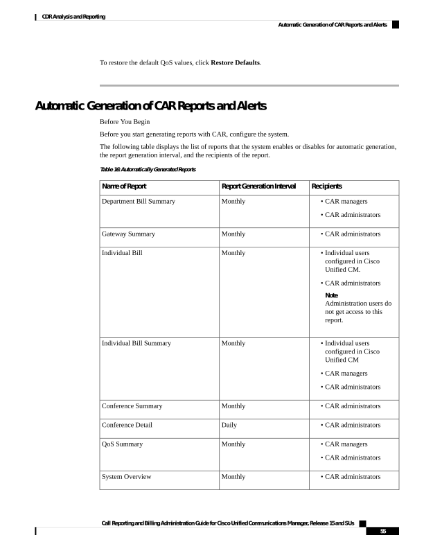
Page 68
Recipients
Report Generation Interval
Name of Report
• CAR managers
• CAR administrators
Daily
Top N Charge
• CAR managers
• CAR administrators
Monthly
Top N Charge
• CAR managers
• CAR administrators
Daily
Top N Duration
• CAR managers
• CAR administrators
Monthly
Top N Duration
• CAR managers
• CAR administrators
Daily
Top N Calls
• CAR managers
• CAR administrators
Monthly
Top N Calls
• CAR administrators
Monthly
Traffic Summary - Day of Month
• CAR administrators
Weekly
Traffic Summary - Day of Week
• CAR administrators
Daily
Traffic Summary - Hour of Day
• CAR administrators
Weekly
Conference Bridge Util - Day of Week
• CAR administrators
Weekly
Voice Messaging Util - Day of Week
• CAR administrators
Weekly
Route Pattern/Hunt Pilot Util - Day of
Week
• CAR administrators
Weekly
Route/Hunt List Util - Day of Week
• CAR administrators
Weekly
Route Group Util - Day of Week
• CAR administrators
Weekly
Line Group Util - Day of Week
• CAR administrators
Weekly
Gateway Util - Day of Week
Call Reporting and Billing Administration Guide for Cisco Unified Communications Manager, Release 15 and SUs
56
CDR Analysis and Reporting
Automatic Generation of CAR Reports and Alerts
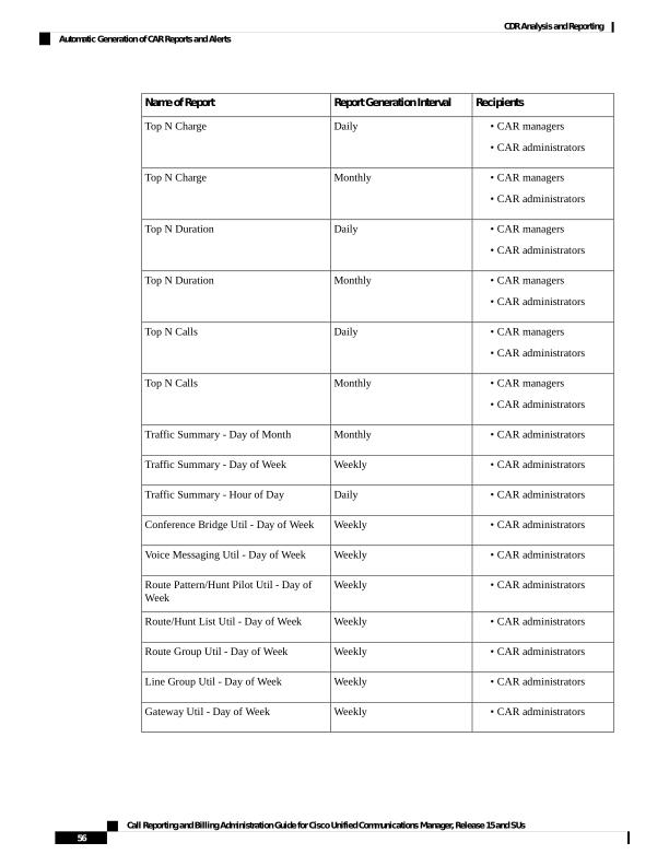
Page 69
In large setups, with a large number of gateways, route groups, route lists, and route patterns, enabling all the
Utilization reports (Gateway Utilization, Line Group Utilization, Route Group Utilization, Route List Utilization,
and Route Pattern Utilization) increases the CPU usage of the system, therefore increasing the time in which
reports are generated. This also affects system performance. Cisco recommends that you enable only Gateway
Utilization reports for automatic generation, due to the number of gateways that are typically found in a large
system. You can generate all Utilization reports on demand by selecting five or less gateways, route groups,
route lists, or route groups.
Note
Automatically generating reports involves a two-step process:
• First, enable the reports that you want to generate unless they are enabled by default.
• Second, schedule the reports for the day and time that you want them to generate. (CAR provides a
default schedule. If the default schedule is acceptable, only enable the reports that you want to generate
automatically.)
CAR provides e-mail alerts for various events. Enabling the system for e-mail alerts involves a two-step
process:
• First, enable the e-mail alerts. Default enables some, but not all, reports.
• Second, configure the e-mail that is sent when the alert criteria are met.
Enable Automatic Generation Reports
This section describes how to enable or disable one or all reports for automatic generation. You can also
customize the report parameters and enable a mailing option, so reports get emaileded when they are created.
When the report gets mailed, CAR generates the email address by using the mail ID for the CAR
administrator(s) and the mail domain that is configured in the Mail Parameters window; that is, CAR uses
<mail ID for the CAR administrator> @ <domain that is configured in the mail parameters window>.
For all new installations of Unified Communications Manager, you must first enable the email alerts and
reports for automatic generation. The default status for all reports and alerts specifies Disabled.
For all Unified Communications Manager upgrades from Release 5.x to a later release of Unified
Communications Manager, the tbl_pregenmail_option table data migrates only if the CAR Scheduler service
is active.
When you upgrade to another version of Unified Communications Manager, disable all reports and alerts
while the upgrade is in process to conserve system resources. Remember to enable the reports and alerts after
the upgrade completes.
The Generated Report Schedule, on page 12 describes reports that are enabled by default.
Procedure
Step 1
Choose Report Config > Automatic Generation/Alert.
The Automatic Report Generation/Alert Option window displays.
Call Reporting and Billing Administration Guide for Cisco Unified Communications Manager, Release 15 and SUs
57
CDR Analysis and Reporting
Enable Automatic Generation Reports

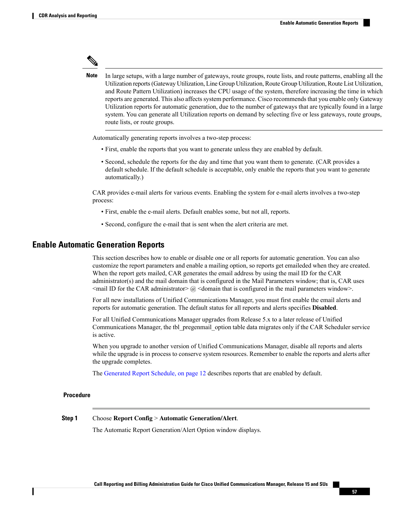
Page 70
Step 2
In the Reports [Report Generation Interval] box, choose the report that you want to automatically generate
based on the schedule that you defined in the System Scheduler. See the Set Up CDR Load Schedule, on page
36.
Step 3
In the Status field, choose Enabled or Disabled.
Step 4
To customize the report or have the report emailed when it is generated, click Customize Parameters.
The Customize Parameters window displays.
Note
Each report provides different customization options, depending on the type of report.
Step 5
Choose the CSV or PDF radio button, depending on the type of report that you want the system to mail.
Step 6
To have the report mailed to all CAR administrators, check the Mailing Option check box.
Step 7
To save the values that you specified, click Update.
The Customize Parameters window closes.
Step 8
To enable or customize other reports, repeat the previous steps.
Step 9
Click Update.
Changes take effect at midnight. You can force the change to take effect immediately by stopping and restarting
the CAR Scheduler service.
Enable Email Alerts
There are two Alerts by Mail that are available. These alerts are:
• Charge Limit Notification
• QoS Notification
See the Set Notification Limits, on page 59 for information on how to configure these alerts.
This section describes how to enable these alerts to be mailed to users.
Procedure
Step 1
Choose Report Config > Automatic Generation/Alert.
The Automatic Report Generation/Alert window displays.
Step 2
In the Alerts by Mail box, choose the alert that you want to enable or disable.
Step 3
In the Status field, choose Enabled or Disabled.
Step 4
Click Update.
Step 5
To enable or disable alerts by mail, repeat the previous steps.
Changes take effect at midnight. You can force the change to take effect immediately by stopping and restarting
the CAR Scheduler service.
Call Reporting and Billing Administration Guide for Cisco Unified Communications Manager, Release 15 and SUs
58
CDR Analysis and Reporting
Enable Email Alerts
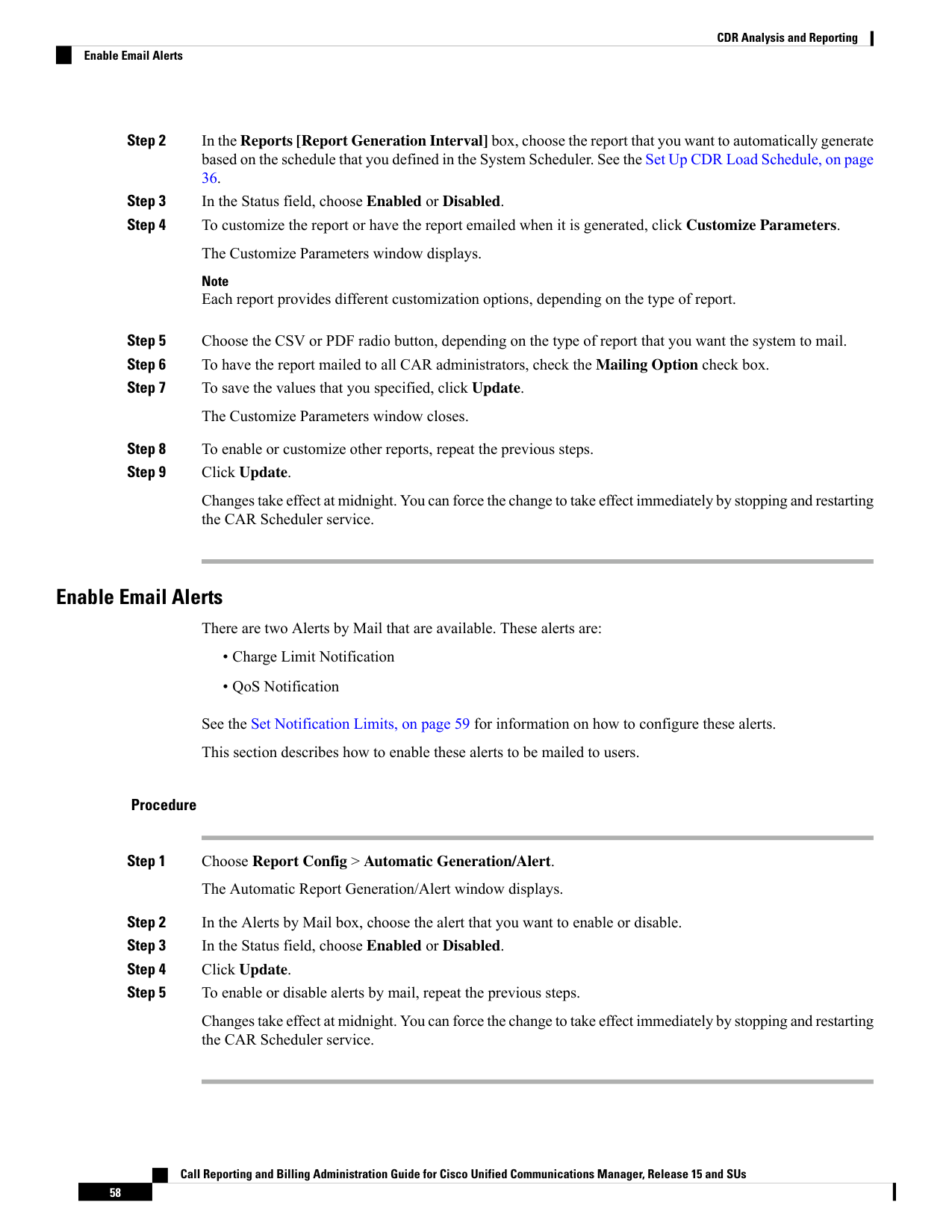
Page 71
CAR Reports Notification Limits
Before You Begin
Before you start generating reports with CAR, configure the system.
Set Notification Limits
This section describes how to specify the notification limits for QoS and daily charges.
Procedure
Step 1
Choose Report Config > Notification Limits.
The Set Limits for Notification window displays.
Step 2
In the Daily QoS Parameters area, enter a threshold for good and poor calls.
The threshold applies in the form of a percentage of all calls that must be exceeded to trigger an email alert
to the administrator. The default for good calls specifies less than 20 percent, meaning that when good calls
represent less than 20 percent of all calls per day, an alert gets sent. The default for poor calls specifies greater
than 30 percent, meaning that when poor calls represent more than 30 percent of all calls per day, an alert gets
sent. The alert is called the QoS Notification.
Step 3
In the Daily Charge Limit area, enter the number of monetary units (such as dollars, francs, or pounds) that,
when exceeded by any user in the system, will trigger sending an email alert to the administrator. The alert
is called the Charge Limit Notification.
Step 4
Click Update.
Changes take effect immediately. The new values get used whenever the next alert is sent.
Call Reporting and Billing Administration Guide for Cisco Unified Communications Manager, Release 15 and SUs
59
CDR Analysis and Reporting
CAR Reports Notification Limits
Page 72
Call Reporting and Billing Administration Guide for Cisco Unified Communications Manager, Release 15 and SUs
60
CDR Analysis and Reporting
Set Notification Limits

Page 73
C H A P T E R 4
User Reports
• User Reports Overview, on page 61
• Bills User Reports, on page 65
• Top N User Reports, on page 68
• Assistant User Reports, on page 74
• IP Phone Service User Reports, on page 76
• Review User Reports Results, on page 77
User Reports Overview
CAR provides reporting capabilities for three levels of users:
• Administrators - Generate system reports to:
• Load balancing
• System performance
• Troubleshooting
• Managers - Generate reports for users, departments, QoS to help with the call monitoring for budgeting
or security purposes, and for determining the voice quality of the calls.
• Individual users - Generate a billing report for their calls.
You may have access restrictions to view some reports depending on your job function.
Note
User Reports Description
Users, managers, and CAR administrators can generate user reports. CAR includes the following user reports:
• Bills
• Individual - Available for users, managers, and CAR administrators. Individual bills provide call
information for the date range that you specify. You can generate, view, or mail summary or detail
Call Reporting and Billing Administration Guide for Cisco Unified Communications Manager, Release 15 and SUs
61


Page 74
information about your individual phone bills. Those CAR administrators who are also application
users cannot get this report.
• Department - Available for managers and CAR administrators. Department bills provide call
information and quality of service (QoS) ratings. If you are a manager, you can generate a summary
or detailed report of the calls that are made by all users who report to you, or only those users that
you choose. If you are a CAR administrator, you can generate a summary or detailed report of the
calls that some or all users in the system make. This report helps you to keep track of all calls on a
user-level basis for the entire system.
• Top N
• By Charge - Available for managers and CAR administrators. The Top N by Charge reports list the
top number of users that incurred a maximum charge for calls during a period that you specify.
Reports that are generated by destinations list the destinations that incurred the maximum charges.
Reports that are generated by all calls list the calls that incurred the maximum charges. If you are
a manager, the report includes the top charges for all calls that are made by users who report to you
during the specified period. If you are a CAR administrator, the report includes the top charges for
all calls that are made by all users on the system for the specified period.
• By Duration - Available for managers and CAR administrators. The Top N by Duration reports list
the top number of users that incurred a maximum time on calls during a period that you specify.
Reports that are generated by destinations list the destinations that incurred the maximum duration.
Reports that are generated by all calls list the calls that incurred the maximum duration. If you are
a manager, the report lists the top number of users who report to you who incurred a maximum time
for calls that are made during the chosen date range, starting with the longest. If you are a CAR
administrator, the report lists the top number of users that incurred a maximum time for calls that
were made during the chosen date range, starting with the longest.
• By Number of Calls - Available for managers and CAR administrators. The Top N by Number of
Calls reports list the users who incurred the maximum number of calls. Reports that extensions
generate list the extensions that placed or received the greatest number of calls during a period that
you specify. If you are a manager, the report lists the top number of calls by user or extension,
among the users who report to you, for the chosen date range. If you are a CAR administrator, the
report lists the top number of calls for each user or extension in the system. Reports that are generated
by Individual Users list the users who incurred the maximum number of calls. Reports that are
generated By Extensions list the extensions that have placed or received the greatest number of calls
in the group (for a manager) or in the system (for the CAR administrator).
• Cisco Unified Communications Manager Assistant
• Manager Call Usage - Available for CAR administrators. The Cisco Unified Communications
Manager Assistant (IPMA) summary and detail reports provide call completion usage details for
IPMA managers. The manager reports can include calls that managers handle for themselves only,
calls that assistants handle for managers only, or calls that both managers and assistants handle for
managers.
• Assistant Call Usage - Available for CAR administrators. The Cisco IPMA summary and detail
reports provide call completion usage details for IPMA assistants. The assistant reports can include
calls that assistants handle for themselves only, calls that assistants handle for managers, calls that
assistants handle for themselves and for managers.
Call Reporting and Billing Administration Guide for Cisco Unified Communications Manager, Release 15 and SUs
62
CDR Analysis and Reporting
User Reports Description
Page 75
• Cisco IP Phone Services - Available for CAR administrators. The Cisco IP Phone Services report shows
selected Cisco IP Phone services, the number of users that are subscribed to each of the selected services,
and the utilization percentage for each of the selected services. You can create services for a wide variety
of business and entertainment uses. If you have revenue that is tied to a service, such as for advertising,
you can use this report to determine the number of users who have subscribed to the service. You can
also use this report to indicate the popularity of the selected services.
Mail Reports
You can email all reports in CAR. You can send a report by mail from any report window in CAR. You can
also view the report first and then send it.
Before you begin
To email reports, first, configure valid mail parameters. The mail parameters allow CAR to send email by
using an email server in your system. See the Set Up Mail Server Parameters, on page 31, for more information.
Also, set up the details of the report that you want generated.
The following procedure describes how to mail a CAR report.
Procedure
Step 1
Within any CAR Reports window or after viewing the report, click Send Report.
The Mail To window displays.
Step 2
Enter the email ID for the user to whom you want to send the report.
Step 3
You can search for a user by clicking the To.
A User Search window displays.
Step 4
In the First Name and Last Name fields, enter characters of the first or last name of the user and click Search.
A User Search Results window displays on the same page and lists all users who matched the search criteria
that you entered.
Step 5
In the row for the user to whom you want to send the report, click the Select link.
The user that you chose gets added to the To field of the Mail To window. Repeat this step to add more users
to the list of people who will be emailed a copy of this report.
Step 6
When you have added all users, click Close in the User Search window.
The users who are listed in the Search Users window get copied to the To field of the Mail To window.
Step 7
To add a user to the Cc field, click the Cc and follow the same instructions as described in Step 4, on page
63 through Step 6, on page 63.
Step 8
In the Subject field, enter a subject message (optional).
Step 9
In the Message area, enter a message (optional).
Step 10
Click Send.
Call Reporting and Billing Administration Guide for Cisco Unified Communications Manager, Release 15 and SUs
63
CDR Analysis and Reporting
Mail Reports
Page 76
View CSV Reports
At times, the data in the CSV report may not be aligned properly. To align the data and view the report in the
right format, do the following:
Procedure
Step 1
Open the CSV report in a web browser.
Step 2
Right-click anywhere on the report and choose View Source.
The report opens as a text file.
Step 3
Save the text file with a CSV file extension.
Step 4
Open the CSV file.
The data is displayed in the right format.
Search Users
Many reports in CAR provide a search function, so you can look for users. The following CAR User reports
support search by user: Department and individual bills, Top N by charge, duration, and a number of calls,
Cisco Unified Communications Manager Assistant, and Cisco Unified IP Phone. You can mail all reports that
can be generated through the Send Report.
Before you begin
You must use the window in User Reports that allows you to search for users.
This section describes how to search for a user.
Procedure
Step 1
Click the Search Users link.
A User Search window displays.
Step 2
In the First Name and Last Name fields, enter characters of the first or last name of the user and click Search.
A User Search Results window displays in the same window and lists all users who matched the search criteria
that you entered.
Step 3
In the row for the user that you want, click Select link.
The user that you chose gets added to the List of Users in the User Search window. Repeat this step to add
more users.
Step 4
When you have added all users, click Close in the User Search window.
Call Reporting and Billing Administration Guide for Cisco Unified Communications Manager, Release 15 and SUs
64
CDR Analysis and Reporting
View CSV Reports
Page 77
Bills User Reports
CAR provides reporting capabilities for three levels of users:
• Administrators - Generate system reports to help with load balancing, system performance, and
troubleshooting.
• Managers - Generate reports for users, departments, and QoS to help with a call monitoring for budgeting
or security purposes and for determining the voice quality of the calls.
• Individual users - Generate a billing report for their calls.
You may have access restrictions to view some reports depending on your job function.
Note
Bills Reports
Individual bills provide the call information for the date range that you specify. You can either view reports
that the system automatically generates or generate new reports. Only CAR administrators can schedule reports
for an automatic generation. If you are an administrator, see Automatic Generation of CAR Reports and Alerts
for more information.
Department bills provide call information and QoS ratings. If you are a manager, you can generate a summary
or detailed report of the calls that all users who report to you made, or only those users that you choose.
If you are a CAR administrator, you can generate a summary or detailed report of the calls that some or all
users in the system made. This report helps you track all the calls on a user-level basis for the entire system.
Purpose
Command or Action
Describes how to view, or mail, summary or
detail information reports about users,
managers, and administrators.
Note
Administration users do not get access to this
report.
Generate Individual Bills Reports
Step 1
Describes how to generate, view, or mail
summary or detail information about
departmental bills.
Note
Application users do not get access to this
report.
Generate Department Bills Reports
Step 2
Call Reporting and Billing Administration Guide for Cisco Unified Communications Manager, Release 15 and SUs
65
CDR Analysis and Reporting
Bills User Reports

Page 78
Generate Individual Bills Reports
Before you can configure the Individual Bills report, you must ensure that a device with an assigned Owner
User ID exists in Cisco Unified CM Administration for each user that included in the report. Use the following
procedure to create the Owner User IDs:
Procedure
Step 1
In Cisco Unified CM Administration, choose Device > Add a New Phone > Phone > Phone Configuration.
Step 2
Add the information for the device and the user.
Note
If the Extension Mobility feature enabled on the device and the user logs in to the phone and places a call,
the User ID that gets recorded in the CDRs matches the logged in User ID. If extension mobility is not enabled
on the device, the User ID that gets recorded in the CDRs equals the “Owner User ID” that is configured for
the device.
In the situation were neither the User ID nor the Owner User ID is configured (that is, extension mobility is
not enabled, and the Owner User ID is not configured), the User ID field in the CDRs gets recorded as blank.
CAR uses the default User ID of “_unspecified user” when it loads the CDRs, and the CDRs do not appear
in the Individual Bills User reports because no user by the name “_unspecifieduser” exists in the Cisco Unified
CM database.
If you look for the reports for a particular end user in the directory, either the User ID for the particular end
user must be configured as the Owner User ID for the device, or the particular end user must have logged in
to the device with the extension mobility feature enabled.
You are now ready to configure the Individual Bills report.
Step 3
Perform one of the following tasks:
a)
Choose Bills > Individual, if you are a user or manager.
b) Choose User Reports > Bills > Individual, If you are a CAR administrator.
Step 4
Choose Summary or Detail in the Report Type field.
Summary reports - Provides a summary of all calls for a chosen period, including the call classification
(Internal, Local, Long Distance, International, or On Net), the QoS information, the total number of calls that
were made, and the charges that were incurred.
Detailed reports - Provides the date of the call, origination time of the call, origination number (calling number),
destination number (called number), call classification (On Net, Internal, Local, Long Distance, International,
or Others), QoS information, duration of time for which the call lasted (in seconds), and the charge for the
call, based on the rating engine configuration in CAR for all calls over a chosen period.
Step 5
Choose an automatically generated report (if available) and go to Step 8, on page 67 or use the default Generate
New Report and go to Step 8, on page 67Step 6, on page 67 In the Available Reports field.
Note
You can only choose the automatically generated report if you are logged in as CAR administrator. The
automatically generated reports do not display in the drop-down list box if you are logged in as a manager or
individual user.
Call Reporting and Billing Administration Guide for Cisco Unified Communications Manager, Release 15 and SUs
66
CDR Analysis and Reporting
Generate Individual Bills Reports
Page 79
Step 6
Choose the date range for the period for which you want to see call information.
Step 7
Choose CSV in the Report Format area, if you want the report in CSV format. Choose PDF in the Report
Format area, if you want the report in PDF format.
Step 8
Click View Report.
Step 9
Click Send Report. If you want to mail the report, follow the procedure that is described in the Mail Reports,
on page 63.
Generate Department Bills Reports
Before you can configure the Department Bills report, you must ensure a device with an assigned Owner User
ID and Manager User ID exists in Cisco Unified CM Administration for each user that is included in the
report. Use the following procedure to add the device, Owner User ID, and the associated Manager User ID
for each user:
Procedure
Step 1
Choose Device > Phone > Add a New Phone > Phone Configuration in Cisco Unified CM Administration.
Step 2
Add the information for the device and the user.
Step 3
Choose User Management > End User > Add, in Cisco Unified CM Administration.
Step 4
Add the Manager User ID information to the end user information.
Note
If the Extension Mobility feature is enabled on the device and the user logs into the phone and places a call,
the User ID that gets recorded in the CDRs is the logged in User ID. If extension mobility is not enabled on
the device, the User ID that gets recorded in the CDRs specifies the “Owner User ID” that is configured for
the device.
In the situation were neither the User ID nor the Owner User ID is configured (that is, extension mobility is
not enabled, and the Owner User ID is not configured), the User ID field in the CDRs gets recorded as blank.
CAR uses the default User ID of “_unspecified user” when it loads the CDRs, and the CDRs are not seen in
the Department Bills User reports because no user by the name “_unspecifieduser” exists in the Cisco Unified
CM database.
If you look for the reports for a particular end user in the directory, either the User ID for the particular end
user must be configured as the Owner User ID for the device or the particular end user must have logged in
to the device with the Extension Mobility feature enabled.
Step 5
Perform one of the following tasks:
a)
Choose Bills > Department, if you are a manager.
b) Choose User Reports > Bills > Department, if you are a CAR administrator.
Step 6
Choose Summary or Detail, in the Report Type field.
Summary reports - Provides a summary of all calls for a chosen period, including the call classification (OnNet,
Internal, Local, Long Distance, International, Incoming, Tandem, or Others), the QoS information, the total
number of calls that were made, and the charges that were incurred.
Detailed reports - Provides the date of the call, origination time of the call, origination number (calling number),
destination number (called number), call classification (On Net, Internal, Local, Long Distance, International,
Call Reporting and Billing Administration Guide for Cisco Unified Communications Manager, Release 15 and SUs
67
CDR Analysis and Reporting
Generate Department Bills Reports
Page 80
or Others), QoS information, duration for which the call lasted (in seconds), and the charge for the call, based
on the rating engine configuration in CAR for all calls over a chosen period.
Step 7
In the Available Reports field, choose an automatically generated report (if available) and go to Step 17, on
page 68 or use the default Generate New Report and go to Step 8, on page 68.
Note
You can only choose the automatically generated report if you are logged in as a CAR administrator. The
automatically generated reports do not display in the drop-down list box if you are logged in as a manager.
Step 8
Choose the date range for the period for which you want to see call information.
Step 9
If you are a manager, continue with Step 10, on page 68; otherwise, if you are a CAR administrator, continue
with Step 14, on page 68.
Step 10
To choose all of your direct reports, check the Select All Reportees check box.
The List of Reportees shows your direct reports.
Note
Click Down to view your direct reports. Use the Up and Down to move up and down the report chain
information.
Step 11
To choose individual reportees, choose the reports that are shown in the List of Reportees.
Step 12
Click Add.
The department bill includes only users who are listed in the Selected Reportees box.
Step 13
To see the reportees under a particular user, choose the user and click Down.
Step 14
If you are a CAR administrator, check the Select All Users check box to include all users. If you are a manager,
proceed to Step 16, on page 68.
Step 15
To specify individual users, enter the user ID of the individual that you want to include in the report in the
User ID field. Click Add.
You can also use a provided user search function. See the Search Users, on page 64, for instructions on using
the search feature.
Step 16
Choose CSV in the Report Format area, if you want the report in CSV format. Choose PDF in the Report
Format area, if you want the report in PDF format.
Step 17
Click View Report.
Step 18
Click Send Report. If you want to mail the report, perform the procedure that is described in the Mail Reports,
on page 63.
Top N User Reports
CAR provides reporting capabilities for three levels of users:
• Administrators - Generate system reports to help with load balancing, system performance, and
troubleshooting.
• Managers - Generate reports for users, departments, and QoS to help with call monitoring for budgeting
or security purposes and for determining the voice quality of the calls.
Call Reporting and Billing Administration Guide for Cisco Unified Communications Manager, Release 15 and SUs
68
CDR Analysis and Reporting
Top N User Reports
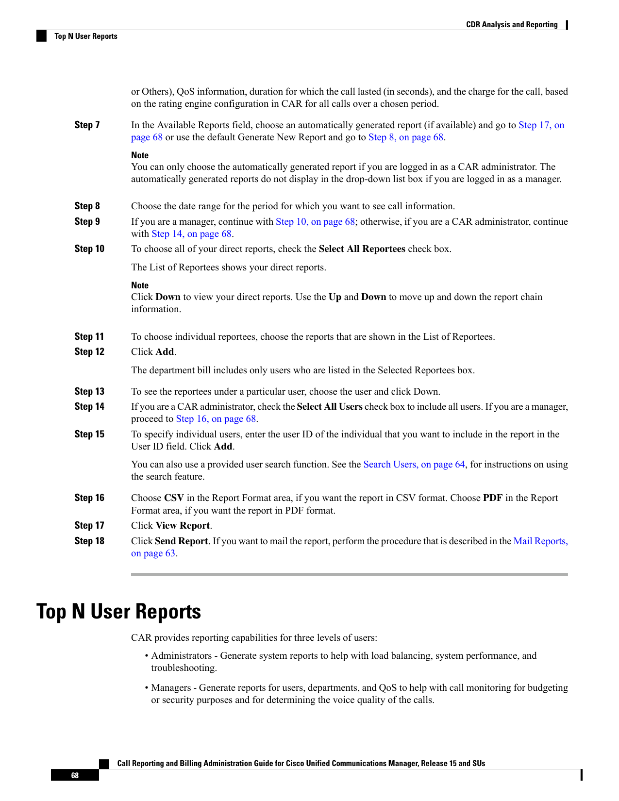
Page 81
• Individual users - Generate a billing report for their calls.
You may have access restrictions to view some reports depending on your job function.
Note
Top N Reports
Top N Charge reports the users who made the maximum charge for the specified date range. If you are a
manager, the report includes the top charges for all calls that users who report to you made during the specified
period. If you are a CAR administrator, the report includes the top charges for all calls that all users on the
system made for the specified period. You can generate each Top N Charge report with options to show the
information by individual users, by destinations, or by all calls.
Top N Duration reports the top number of users that incurred a maximum time on calls during a period that
you specify. If you are a manager, the report lists the top number of users who report to you that incurred a
maximum time for calls that were made during the chosen date range, starting with the longest. If you are a
CAR administrator, the report lists the top number of users that incurred a maximum time for calls that were
made during the chosen date range, starting with the longest. You can generate each Top N Duration report
with options to show the information by individual users, by destinations, or by all calls.
Top N Number of Calls reports the top number of calls that were made and received by users during a period
that you specify. If you are a manager, the report lists the top number of calls by users among the users who
report to you for the chosen date range. If you are a CAR administrator, the report lists the top number of calls
for each user in the system. You can generate each Top N Number of Calls report with options to show the
information by individual users and by extensions.
Generate Top N by Charge Reports
This section describes how to generate, view, or mail reports about the top calls when classified by cost.
Procedure
Step 1
Perform one of the following tasks:
a)
Choose Top N > By Charge, if you are a manager.
b) Choose User Reports > Top N > By Charge, if you are a CAR administrator.
Step 2
In the Select Call Types area, check the check boxes for the types of calls that you want the report to include.
These boxes display only when you choose Generate New Report from the Available Reports drop-down list
box, as described in the following table. The next table describes the call types.
Tip
To check all check boxes, click Select All; to uncheck the check boxes, click Clear All.
Call Reporting and Billing Administration Guide for Cisco Unified Communications Manager, Release 15 and SUs
69
CDR Analysis and Reporting
Top N Reports

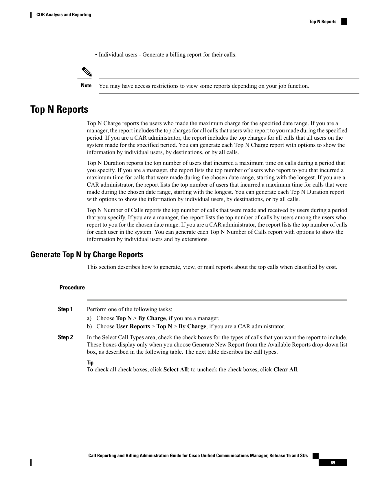
Page 82
Table 17: Top N by Charge Call Types
Description
Call Type
Outgoing calls that originate on one Unified Communications Manager network, go
out through a trunk, and terminate on a different Unified Communications Manager
network. For CAR purposes, be aware that any outgoing call can be classified as an
OnNet call if it is configured as such in the CAR dial plan configuration window.
SeeSet Up Dial Plan, on page 31 .
On Net
Calls, including intracluster calls, that originate in the Unified Communications Manager
network and end in the same Unified Communications Manager network (no gateways
or trunks are used).
Internal
Local calls that are routed through the public switched telephone network (PSTN) to
numbers without an area code or that include one of the local area codes.
Local
Long-distance calls that originate in the Unified Communications Manager network
going out through the PSTN.
Long Distance
International calls that originate in the Unified Communications Manager network and
go out through the PSTN.
International
Inbound calls that originate outside the Unified Communications Manager network
and enter the Unified Communications Managernetwork through a gateway.
Incoming
Inbound calls that originate outside the Unified Communications Manager network,
enter the Unified Communications Managernetwork through a gateway, and transfer
outbound from the Unified Communications Managernetwork through a gateway.
Tandem
All other outgoing calls, such as toll-free numbers or emergency calls such as 911.
Others
Step 3
In the Report Type field, choose a report type as described in the following table.
Table 18: Top N by Charge Report Types
Description
Report Type
This report lists the users who incurred the maximum charges.
By Individual Users
This report lists the destinations that incurred the maximum charges.
By Destinations
This default report lists the calls that incurred the maximum charges.
By All Calls
Note
Top N Destination by Charge reports display the top destinations based on the charge incurred. If the same
destination number comprises different call classifications (for example, some are Internal, and some are
Incoming), they get treated and listed separately in these reports.
Step 4
In the Available Reports field, choose an automatically generated report (if available) and go to the table or
use the default setting, Generate New Report, and go to the table.
Note
Call Reporting and Billing Administration Guide for Cisco Unified Communications Manager, Release 15 and SUs
70
CDR Analysis and Reporting
Generate Top N by Charge Reports

Page 83
You can only choose the automatically generated report if you are logged in as CAR administrator. The
automatically generated reports do not display in the drop-down list box if you are logged in as a manager.
Step 5
Enter the number (n) of records to display in the report in the No of Records field. The default designates
five.
Step 6
Choose the date range for the period for which you want to generate the report.
Step 7
Choose CSV in the Report Format area, if you want the report in CSV format. Choose PDF in the Report
Format area, if you want the report in PDF format.
Step 8
Click View Report.
Step 9
Click Send Report. To send the report, perform the procedure that is described in the Mail Reports, on page
63.
Generate Top N by Duration Reports
This section describes how to generate, view, or mail reports about the top calls when they are classified by
duration.
Procedure
Step 1
Perform one of the following tasks:
a)
Choose Top N > By Duration., if you are a manager
b) Choose User Reports > Top N > By Duration., if you are a CAR administrator.
Step 2
In the Select Call Types area, check the check boxes for the types of calls that you want included in the report.
These boxes display only when you choose Generate New Report from the Available Reports drop-down list
box, as described in the following table. The next table describes the call types.
Table 19: Top N by Duration Call Types
Description
Call Type
Outgoing calls that originate on one Unified Communications Managernetwork,
go out through a trunk, and terminate on a different Unified Communications
Managernetwork. For CAR purposes, be aware that any outgoing call can be
classified as an OnNet call if it is configured as such in the CAR dial plan
configuration window. See Set Up Dial Plan, on page 31.
On Net
Calls, including intracluster calls, that originate in the Unified Communications
Manager network and end in the same Unified Communications Managernetwork
(no gateways or trunks are used).
Internal
Local calls that are routed through the public switched telephone network (PSTN)
to numbers without an area code or that include one of the local area codes.
Local
Long-distance calls that originate in the Unified Communications Managernetwork
going out through the PSTN.
Long Distance
Call Reporting and Billing Administration Guide for Cisco Unified Communications Manager, Release 15 and SUs
71
CDR Analysis and Reporting
Generate Top N by Duration Reports
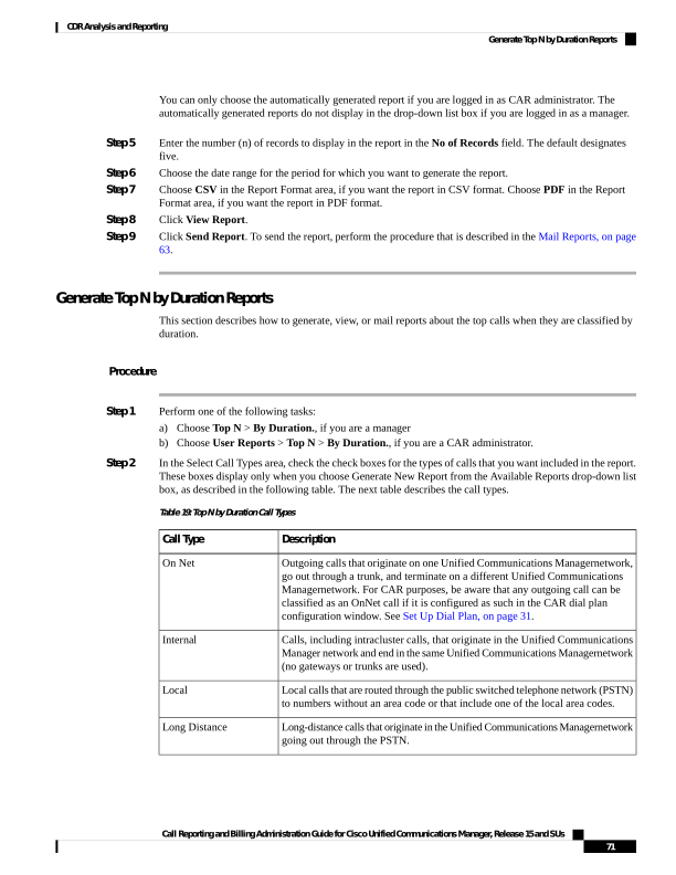
Page 84
Description
Call Type
International calls that originate in the Unified Communications Manager network
and go out through the PSTN.
International
Inbound calls that originate outside the Unified Communications Manager
network, enter through a gateway, and go into the Unified Communications
Manager network.
Incoming
Inbound calls that originate outside the Unified Communications Managernetwork,
enter the Unified Communications Manager network through a gateway, and
then are transferred outbound from the Unified Communications Manager network
through a gateway.
Tandem
All other outgoing calls, such as toll-free numbers or emergency calls such as
911.
Others
Step 3
In the Report Type field, choose a report type as described in the following table.
Table 20: Top N by Duration Report Types
Description
Report Type
This report lists the users who incurred the maximum duration.
By Individual Users
This report lists the destinations that incurred the maximum duration.
By Destinations
This report lists the calls that incurred the maximum duration.
By All Calls
Note
Top N Destinations by Duration reports display the top destinations based on the duration of the calls. If the
same destination number comprises different call classifications (for example, some are Internal and some
are Incoming), they get treated and listed separately in these reports.
Step 4
In the Available Reports field, choose an automatically generated report (if available) and go to the table or
use the default setting, Generate New Report and go to the table.
Note
You can only choose the automatically generated report if you are logged in as a CAR administrator. The
automatically generated reports do not display in the drop-down list box if you are logged in as a manager.
Step 5
Enter the number (n) of records to display in the report in the No of Records field. The default designates
five.
Step 6
Choose the date range for the period for which you want to generate the report.
Step 7
Choose CSV in the Report Format area, if you want the report in CSV format. Choose PDF in the Report
Format area, if you want the report in PDF format.
Step 8
Click View Report.
Step 9
Click Send Report, if you want to mail the report button. To send the report, perform the procedure that is
described in the Mail Reports, on page 63.
Call Reporting and Billing Administration Guide for Cisco Unified Communications Manager, Release 15 and SUs
72
CDR Analysis and Reporting
Generate Top N by Duration Reports
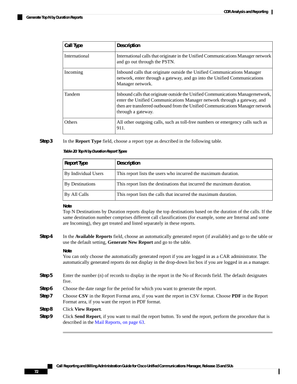
Page 85
Generate Top N by Number of Calls Reports
This section describes how to generate, view, or mail reports about the top calls when classified by volume.
Procedure
Step 1
Perform one of the following tasks:
a)
Choose Top N > By Number of Calls, if you are a manager.
b) Choose User Reports > Top N > By Number of Calls, if you are a CAR administrator.
Step 2
In the Select Call Types area, check the check boxes for the types of calls that you want included in the report.
These boxes display only when you choose Generate New Report from the Available Reports drop-down
list box, as described in the following table. The next table describes the call types.
Table 21: Top N by Number of Calls Call Types
Description
Call Type
Outgoing calls that originate on one Unified Communications Manager network,
go out through a trunk, and terminate on a different Unified Communications
Manager network. For CAR purposes, be aware that any outgoing call can be
classified as an OnNet call if it is configured as such in the CAR dial plan
configuration window. See Set Up Dial Plan, on page 31.
On Net
Calls, including intracluster calls, that originate in the Unified Communications
Manager network and end in the same Unified Communications Manager network
(no gateways or trunks are used).
Internal
Local calls that are routed through the public switched telephone network (PSTN)
to numbers without an area code or that include one of the local area codes.
Local
Long-distance calls that originate in the Unified Communications Manager
network going out through the PSTN.
Long Distance
International calls that originate in the Unified Communications Manager network
and go out through the PSTN.
International
Inbound calls that originate outside the Unified Communications Manager
network, enter through a gateway, and go into the Unified Communications
Manager network.
Incoming
Inbound calls that originate outside the Unified Communications Managernetwork,
enter the Unified Communications Manager network through a gateway, and
transfer outbound from the Unified Communications Manager network through
a gateway.
Tandem
All other outgoing calls, such as toll-free numbers or emergency calls such as
911.
Others
Step 3
In the Report Type field, choose a report type as described in the following table.
Call Reporting and Billing Administration Guide for Cisco Unified Communications Manager, Release 15 and SUs
73
CDR Analysis and Reporting
Generate Top N by Number of Calls Reports
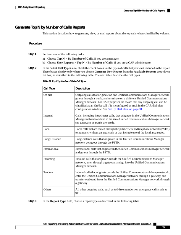
Page 86
Table 22: Top N by Number of Calls Report Types
Description
Report Type
This report lists the users who incurred the maximum number of calls.
By Individual Users
This report lists the extensions that have placed or received the greatest number
of calls in your group (managers) or the system (CAR administrators).
By Extensions
Step 4
In the Available Reports field, choose an automatically generated report (if available) and go to the table or
use the default Generate New Report and go to the table.
Note
You can only choose the automatically generated report if you are logged in as a CAR administrator. The
automatically generated reports do not display in the drop-down list box if you are logged in as a manager.
Step 5
Enter the number (n) of records that display in the report in the No of Records field. The default designates
five.
Step 6
Choose the date range for the period for which you want to generate the report.
Step 7
Choose CSV in the Report Format area, if you want the report in CSV format. Choose PDF in the Report
Format area, if you want the report in PDF format.
Step 8
Click View Report.
Step 9
Click Send Report, if you want to mail the report. To send the report, perform the procedure that is described
in the Mail Reports, on page 63.
Assistant User Reports
CAR provides reporting capabilities for three levels of users:
• Administrators - Generate system reports to help with load balancing, system performance, and
troubleshooting.
• Managers - Generate reports for users, departments, and QoS to help with call monitoring for budgeting
or security purposes and for determining the voice quality of the calls.
• Individual users - Generate a billing report for their calls.
You may have access restrictions to view some reports depending on your job function.
Note
Assistant Usage Reports
CAR provides call completion usage reports for the following Cisco Unified Communications Manager
Assistant users: manager(s) and the configured/assigned assistant(s) that manage the calls of the manager(s).
Only CAR administrators can generate the Cisco Unified Communications Manager Assistant reports. The
Cisco Unified Communications Manager Assistant menu allows you to choose all or a subset of managers or
assistants by using simple search functionality that is based on partial or complete first or last name. You can
Call Reporting and Billing Administration Guide for Cisco Unified Communications Manager, Release 15 and SUs
74
CDR Analysis and Reporting
Assistant User Reports

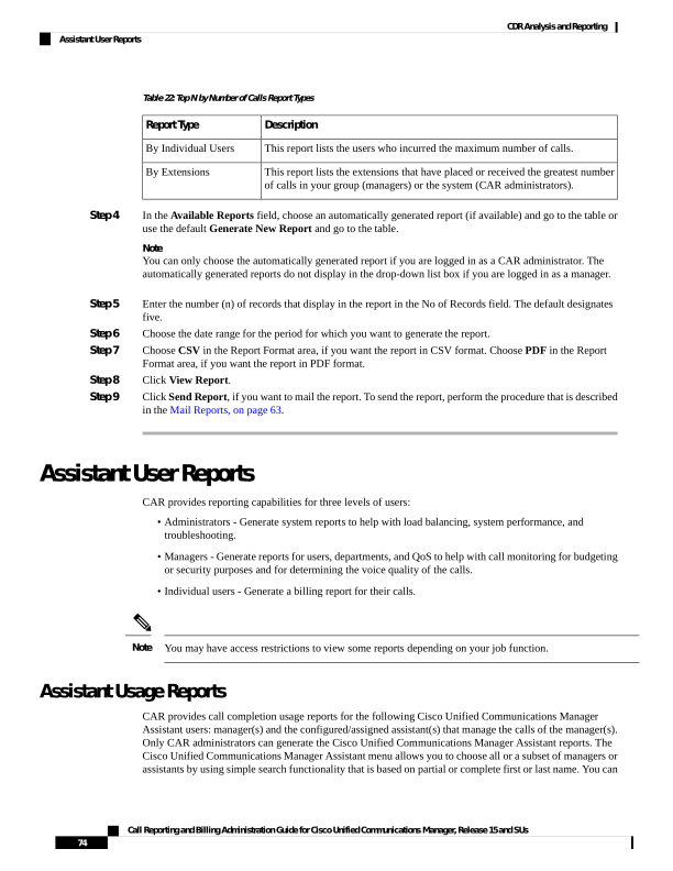
Page 87
generate these reports on demand in either PDF or CSV format and email them. In addition, you can choose
the time range and generate either detailed or summary level reports.
The manager reports can include calls that only managers handle for themselves, calls that only assistants
handle for managers, and calls that qualify in either case. The summary report for a manager shows the number
of calls of each call classification type, the total number of calls, and the total duration of all calls (in seconds)
for each manager and/or assistant. The detail report for a manager shows the date, origination time, origination
number (calling number), destination (called number), call classification, and duration (in seconds) for each
call for each manager and/or assistants and the cumulative duration total for the manager.
The assistant reports can include calls that only assistants handle for themselves, or calls that only assistants
handle for managers, and calls that qualify in either case. The summary report for an assistant shows the
number of calls of each type and total of them apart from duration for each manager (and/or assistant). The
detail assistant report shows the date, origination time, origination (calling number), destination (called
number), call classification, and duration (in seconds) for each call for all the managers (and/or assistant) and
the cumulative duration total for the assistant.
This section contains the following procedures:
• Generate Manager Call Usage Assistant Reports
• Generate Assistant Call Usage Assistant Reports
Generate Manager Call Usage Assistant Reports
This section describes how to generate a manager call usage report for Cisco Unified Communications Manager
Assistant. Only CAR administrators can generate Cisco Unified Communications Manager Assistant reports.
Procedure
Step 1
Choose User Reports > Cisco Unified Communications Manager Assistant > Manager Call Usage.
The Call Usage for Manager window displays.
Step 2
From the Report Type drop-down list, choose either Summary or Detail.
Step 3
From the Calls handled by drop-down list, choose Manager, Assistant for Manager, or Manager & Assistant
for Manager.
Step 4
Choose the date range for the period for which you want to see call information.
Step 5
In the Select Manager(s) box, either check the Select All Manager(s) check box and enter a manager ID or
click the Select Manager(s) link to search for a manager ID and enter the ID(s) in the Manager Id field.
Step 6
Click Add.
The ID that you chose displays in the Selected Manager(s) box.
Step 7
Choose CSV in the Report Format area, if you want the report in CSV format. Choose PDF in the Report
Format area, if you want the report in PDF format.
Step 8
Click Send Report, if you want to mail the report. To send the report, perform the procedure that is described
in the Mail Reports, on page 63.
Note
Call Reporting and Billing Administration Guide for Cisco Unified Communications Manager, Release 15 and SUs
75
CDR Analysis and Reporting
Generate Manager Call Usage Assistant Reports
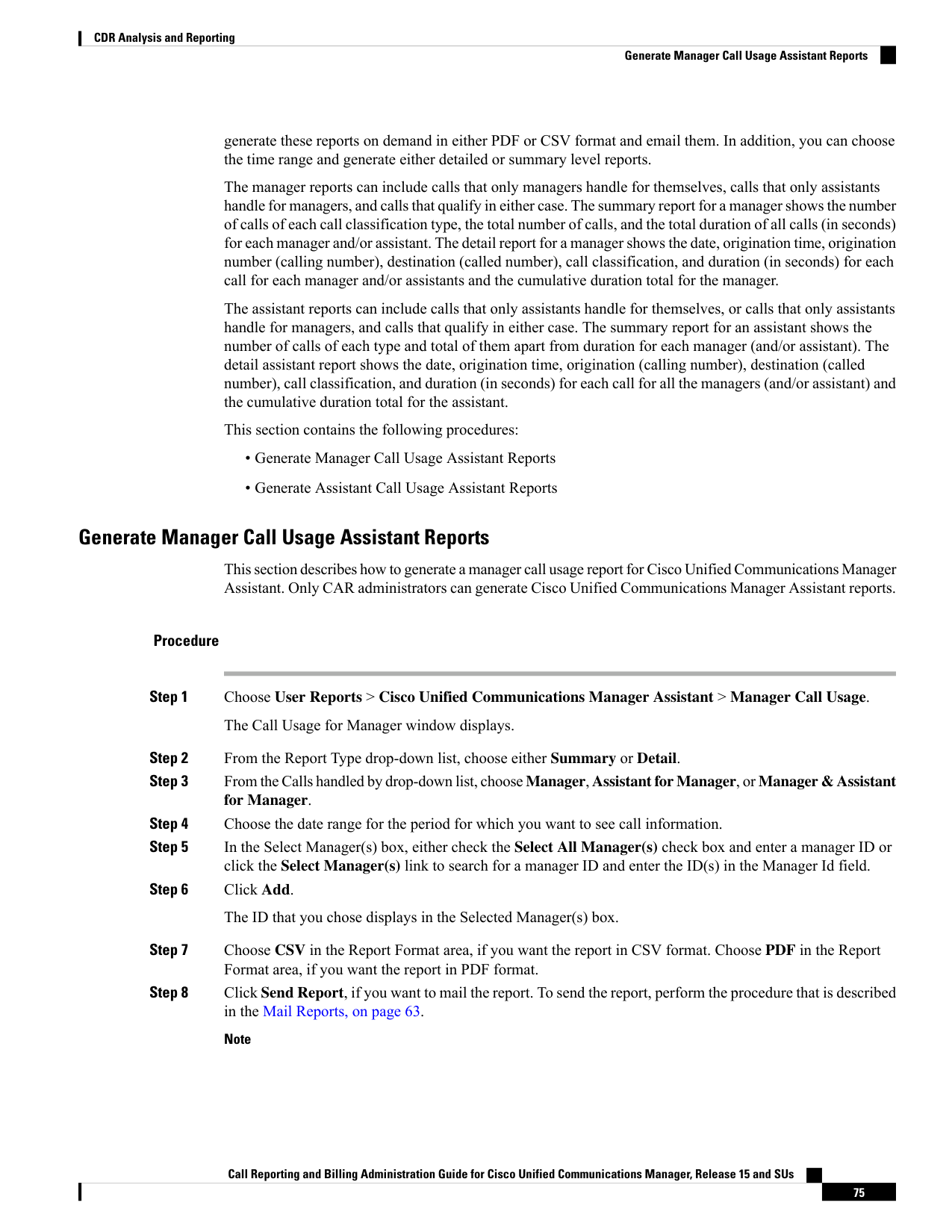
Page 88
To remove a manager from the Selected Manager(s) list, highlight the ID and click Remove. To remove all
managers from the list, click Remove All.
Generate Assistant Call Usage Assistant Reports
This section describes how to generate an assistant call usage report for Cisco Unified Communications
Manager Assistant. Only CAR administrators can generate these reports.
Procedure
Step 1
Choose User Reports > CiscoUnified Communications Manager Assistant > Assistant Call Usage.
The Call Usage for Assistant window displays.
Step 2
From the Report Type drop-down list, choose either Summary or Detail.
Step 3
From the Calls handled by drop-down list, choose Assistant, Assistant for Manager, or Assistant & Assistant
for Manager.
Step 4
Choose the date range for the period for which you want to see call information.
Step 5
In the Select Assistant(s) box, either check the Select All Assistant(s) check box and enter an assistant ID or
click Select Assistant(s) link to search for an assistant ID and enter the ID(s) in the Assistant Id field.
Step 6
Click Add.
The ID that you chose displays in the Selected Assistant(s) box.
Step 7
Choose CSV in the Report Format area, if you want the report in CSV format. Choose PDF in the Report
Format area, if you want the report in PDF format.
Step 8
Click View Report.
Step 9
Click Send Report, if you want to mail the report. To send the report, perform the procedure that is described
in the Mail Reports, on page 63 .
Note
To remove a manager from the Selected Assistant(s) list, highlight the ID and click Remove. To remove all
assistants from the list, click Remove All.
Step 10
When you have added all users, click Close in the User Search window.
IP Phone Service User Reports
CAR provides reporting capabilities for three levels of users:
• Administrators - Generate system reports to help with load balancing, system performance, and
troubleshooting.
• Managers - Generate reports for users, departments, and QoS to help with call monitoring for budgeting
or security purposes and for determining the voice quality of the calls.
Call Reporting and Billing Administration Guide for Cisco Unified Communications Manager, Release 15 and SUs
76
CDR Analysis and Reporting
Generate Assistant Call Usage Assistant Reports
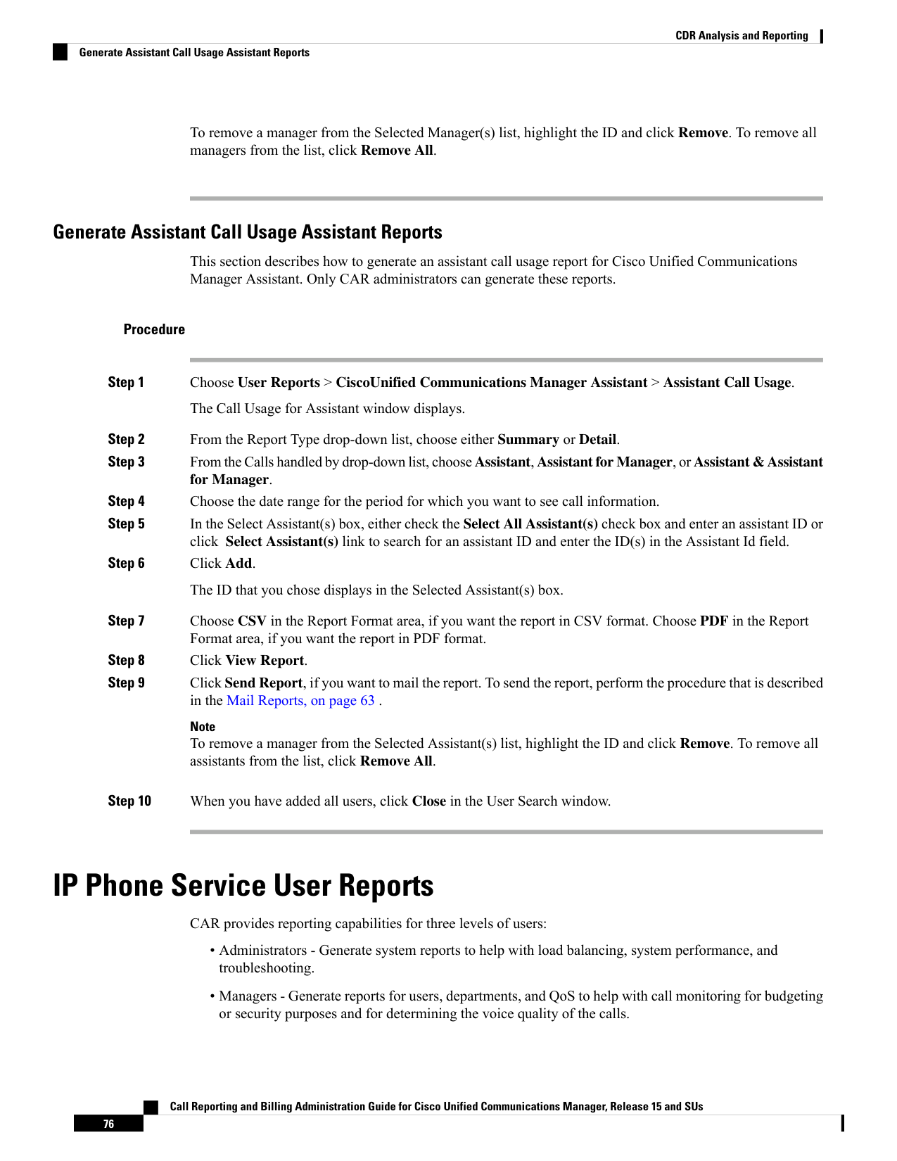
Page 89
• Individual users - Generate a billing report for their calls.
You may have access restrictions to view some reports depending on your job function.
Note
Generate IP Phone Services Reports
Only CAR administrators can generate the Cisco IP Phone Services report. You can generate a report that
shows chosen Cisco IP Phone services, the number of users who are subscribed to each of the chosen services,
and the subscription percentage for each of the chosen services.
Use the following instructions to generate a report that shows the usage of one of the following specific Cisco
Unified IP Phone services:
• Missed calls
• Received calls
• Placed calls
• Intercom calls
• Personal directory
• Corporate directory
• Extension mobility
Procedure
Step 1
Choose User Reports > Cisco IP Phone.
The Cisco IP Phone window displays a list of all Cisco Unified IP Phone services that have been configured
in the system.
Step 2
In the List of Cisco IP Phone area, choose the services that you want to include in the report.
Step 3
Click the right arrow to add the chosen service to the Selected Cisco IP Phone box.
The report includes all services that are listed in this box when you generate it.
Step 4
Choose CSV in the Report Format area, if you want the report in CSV format. Choose PDF in the Report
Format area, if you want the report in PDF format.
Step 5
Click Send Report, if you want to mail the report. To send the report, perform the procedure that is described
in the Mail Reports, on page 63.
Review User Reports Results
This chapter describes report output information for each CAR user report.
Call Reporting and Billing Administration Guide for Cisco Unified Communications Manager, Release 15 and SUs
77
CDR Analysis and Reporting
Generate IP Phone Services Reports

Page 90
Bill Summary Report Results
The report combines information in groups by the username in ascending order. The summary report includes
the following fields (see the following table).
Table 23: Summary Report Fields
Description
Field
Call Classification - Call categories specify classes.
Outgoing calls that originate on one Unified Communications Manager network,
go out through a trunk, and terminate on a different Unified Communications
Manager network. For CAR purposes, be aware that any outgoing call can be
classified as an OnNet call if it is configured as such in the CAR dial plan
configuration window. See Set Up Dial Plan, on page 31.
On Net
Calls, including intracluster calls, that originate in the Unified Communications
Managernetwork and end in the same Unified Communications Manager network
(no gateways or trunks are used).
Internal
Local calls that are routed through the public switched telephone network (PSTN)
to numbers without an area code or that include one of the local area codes.
Local
Long-distance calls that originate in the Unified Communications Manager
network that go out through the PSTN.
Long Distance
International calls that originate in the Unified Communications Manager network
and go out through the PSTN.
International
All other outgoing calls, such as toll-free numbers or emergency calls such as
911.
Others
The number of calls for each Quality of Service category. Parameters that the
CAR administrator sets provide the basis for the following QoS categories:
• Good - QoS for these calls designates the highest possible quality.
• Acceptable - QoS for these calls shows them slightly degraded but still
within an acceptable range.
• Fair - QoS for these calls, that although degraded, still fall within a usable
range.
• Poor - QoS for these calls get categorized as unsatisfactory.
• NA - These calls do not match any criteria for the established QoS categories.
See the Define QoS Values, on page 54 and the Generate QoS by Gateway
Reports, on page 100.
QOS
Indicates the number of calls for each call classification.
Calls
Call Reporting and Billing Administration Guide for Cisco Unified Communications Manager, Release 15 and SUs
78
CDR Analysis and Reporting
Bill Summary Report Results
Page 91
Description
Field
Indicates the charge that is associated with each call. Call charge information
that the CAR administrator provides for the CAR rating engine provides basis
for charges. See CAR Rating Engine, on page 51.
Charge
The following figures display sample output from the Individual Bill and Department Bill Summary reports.
Figure 2: Individual Bill Summary Report Sample
Call Reporting and Billing Administration Guide for Cisco Unified Communications Manager, Release 15 and SUs
79
CDR Analysis and Reporting
Bill Summary Report Results
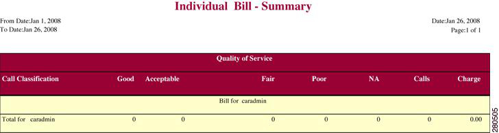
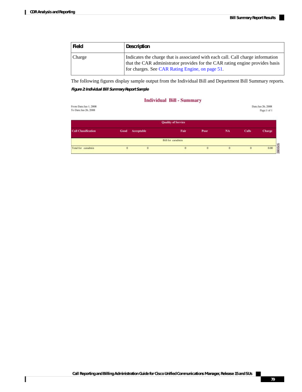
Page 92
Figure 3: Department Bill Summary Report Sample
Bill Detail Report Results
The report places information in groups by the username in ascending order. The detail report includes the
following fields (see the following table).
Table 24: Detail Report Fields
Description
Field
The date that the call originated.
Date
The time that the call originated.
Orig. Time
The originating number from which the call was placed.
Orig.
The destination number to which the call was directed.
Dest.
Call Reporting and Billing Administration Guide for Cisco Unified Communications Manager, Release 15 and SUs
80
CDR Analysis and Reporting
Bill Detail Report Results
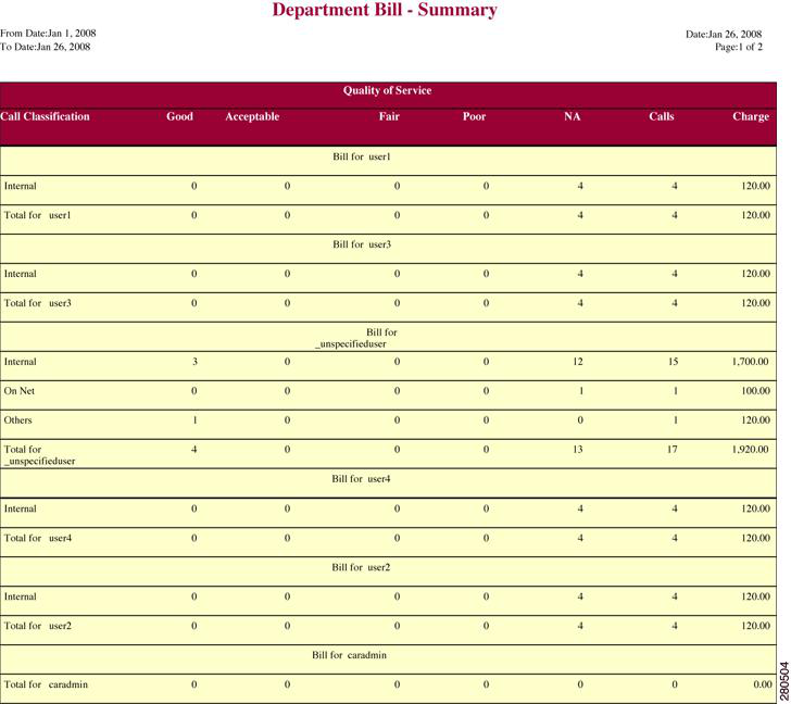
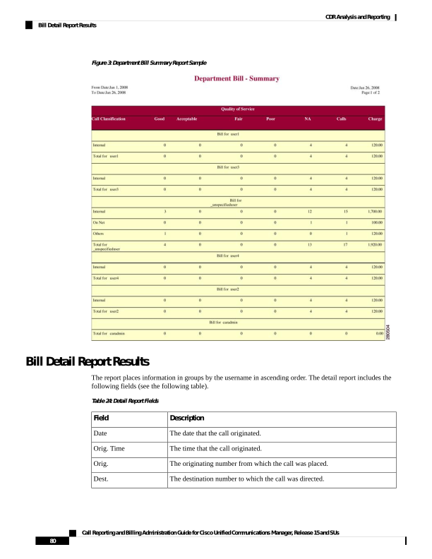
Page 93
Description
Field
Call Classification - Call categories specify classes.
Outgoing calls that originate on one Unified Communications Manager network,
go out through a trunk, and terminate on a different Unified Communications
Manager network. For CAR purposes, be aware that any outgoing call can be
classified as an OnNet call if it is configured as such in the CAR dial plan
configuration window. See Set Up Dial Plan, on page 31.
On Net
Calls, including intracluster calls, that originate in the Unified Communications
Manager network and end in the same Unified Communications Manager network
(no gateways or trunks are used).
Internal
Local calls that are routed through the public switched telephone network (PSTN)
to numbers without an area code or that include one of the local area codes.
Local
Long-distance calls that originate in the Unified Communications Manager
network that go out through the PSTN.
Long Distance
International calls that originate in the Unified Communications Manager network
and go out through the PSTN.
International
All other outgoing calls, such as toll-free numbers or emergency calls such as
911.
Others
The number of calls for each Quality of Service category. Parameters that the
CAR administrator sets provide the basis for the following QoS categories:
• Good - QoS for these calls designates the highest possible quality.
• Acceptable - QoS for these calls shows them slightly degraded but still
within an acceptable range.
• Fair - QoS for these calls, that although degraded, still fall within a usable
range.
• Poor - QoS for these calls get categorized as unsatisfactory.
• NA - These calls do not match any criteria for the established QoS categories.
See the Define QoS Values, on page 54 and the Generate QoS by Gateway
Reports, on page 100.
QOS
The time, in seconds, that the call remains connected.
Duration(s)
The charge that is associated with each call. Call charge information that the
CAR administrator provided for the CAR rating engine provides the basis for
charges. See the Define QoS Values, on page 54.
Charge
The following figures display a sample output from the Individual Bill and Department Bill Detail reports.
Call Reporting and Billing Administration Guide for Cisco Unified Communications Manager, Release 15 and SUs
81
CDR Analysis and Reporting
Bill Detail Report Results
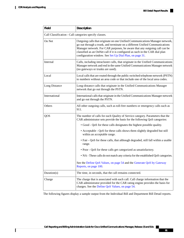
Page 94
Figure 4: Individual Bill Detail Sample Report
Figure 5: Department Bill Detail Sample Report
Top N by Charge or Duration Report Results
The fields for the Top N by Charge and the Top N by Duration vary depending on the report type. The reports
show only outgoing calls. See the table.
Call Reporting and Billing Administration Guide for Cisco Unified Communications Manager, Release 15 and SUs
82
CDR Analysis and Reporting
Top N by Charge or Duration Report Results
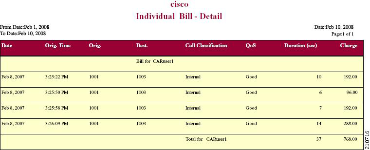
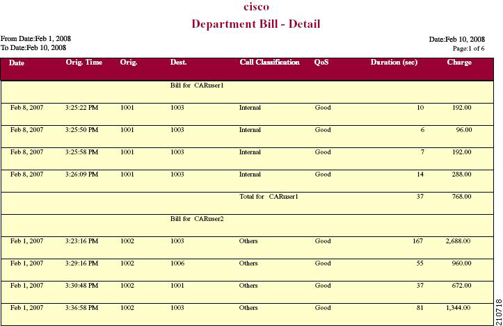
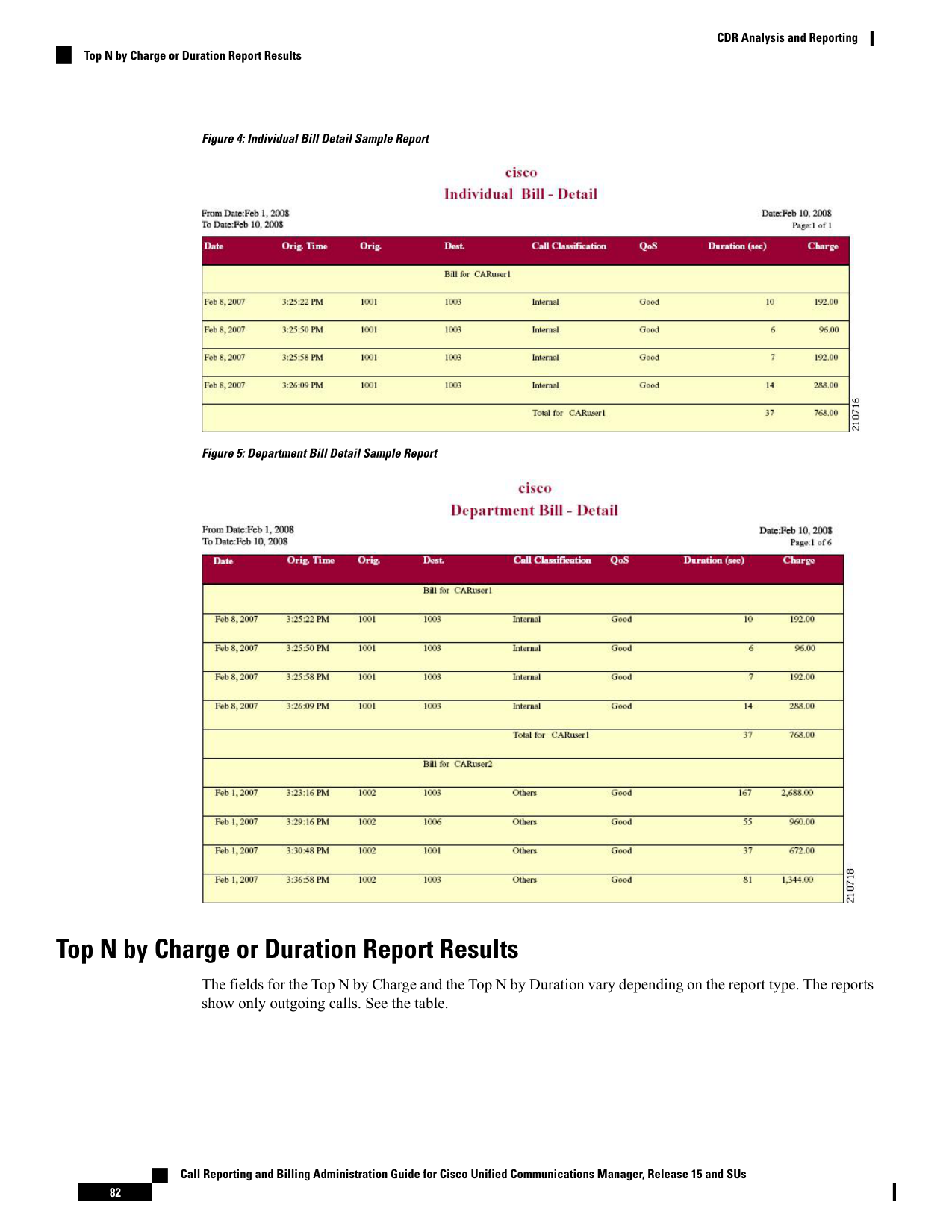
Page 95
Table 25: Top N by Charge and by Duration Report Fields
Description
Field
By Individual Users
User names.
User
Total number of calls.
Calls
The time, in seconds, that the call was connected.
Duration(s)
The charge that is associated with each call. Call charge information that the
CAR administrator provided for the CAR rating engine provides basis for charges.
See the Define QoS Values, on page 54.
Charge
By Destinations
The destination of the calls.
Dest
The total number of calls for each call classification.
Call Classification
Total number of calls.
Calls
The time, in seconds, that the call was connected.
Duration
The charge that is associated with each call. Call charge information that the
CAR administrator provided for the CAR rating engine provides basis for charges.
See CAR Rating Engine, on page 51.
Charge
By Number of Calls
User names.
User
Date that the call occurred.
Date
Time that the call originated.
Orig Time
Origin of the call.
Orig
Destination of the call.
Dest
The total number of calls for each call classification.
Call Classification
The time, in seconds, that the call was connected.
Duration
The charge that is associated with each call. Call charge information that the
CAR administrator provided for the CAR rating engine provides basis for charges.
See CAR Rating Engine, on page 51.
Charge
Figure 6: Top N Charge by Destinations Sample Report, on page 84 and Figure 7: Top N Duration by
Destinations Sample Report, on page 84 display sample reports.
Call Reporting and Billing Administration Guide for Cisco Unified Communications Manager, Release 15 and SUs
83
CDR Analysis and Reporting
Top N by Charge or Duration Report Results
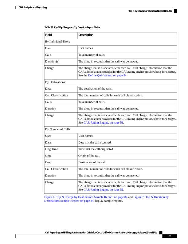
Page 96
Figure 6: Top N Charge by Destinations Sample Report
Figure 7: Top N Duration by Destinations Sample Report
Top N by Number of Calls Report Results
The fields for the Top N by Number of Calls report vary depending on the report type. The report shows both
incoming and outgoing calls. See the table.
Table 26: Top N by Number of Calls Report Fields
Description
Field
By Individual Users
User names.
Users
The total amount of billing charges for all calls to that
user. Call charge information that the CAR
administrator provided for the CAR rating engine
provides basis for charges. See CAR Rating Engine,
on page 51.
Charge
Call Reporting and Billing Administration Guide for Cisco Unified Communications Manager, Release 15 and SUs
84
CDR Analysis and Reporting
Top N by Number of Calls Report Results
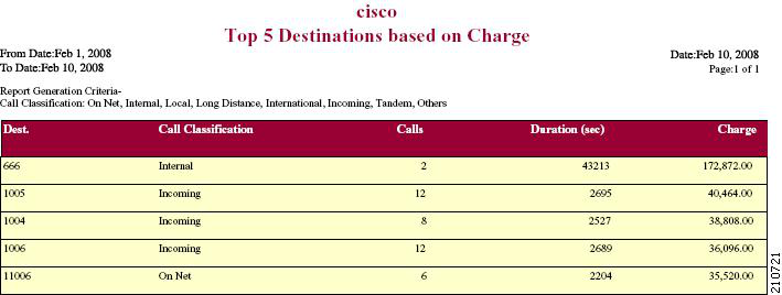
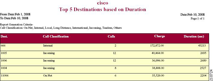
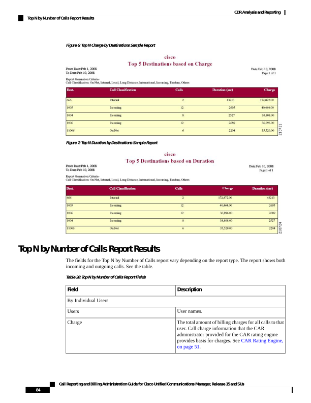
Page 97
Description
Field
The time, in seconds, that the call connected.
Duration(s)
The total number of calls that the user placed.
Calls Made
The total number of calls that the user received.
Calls Received
The total number of incoming and outgoing calls.
Total Calls
By Extensions
The extension that originated/placed and received the
call.
Extension No
The total amount of billing charges for all calls to that
user. Call charge information that the CAR
administrator provided for the CAR rating engine
provides basis for charges. See CAR Rating Engine,
on page 51.
Charge
The time, in seconds, that the call was connected.
Duration
The total number of calls that the user placed.
Calls Made
The total number of calls that the user received.
Calls Received
The total number of incoming and outgoing calls.
Total Calls
Figure 8: Top N by Number of Calls Report Sample Output, on page 85 displays sample report output of Top
N by Number of Calls by Individual Users in PDF format.
Figure 8: Top N by Number of Calls Report Sample Output
Call Usage for Assistant Detail Report Results
The report, which supports Cisco Unified Communications Manager Assistant, shows the number of calls
that assistants handled for themselves, that the assistant handled for each manager, and the total number of
calls that the assistant handled. The report places information in groups about calls that the assistant handled
and calls that the assistant handled for the manager. The detail report includes the following fields (see the
following table).
Call Reporting and Billing Administration Guide for Cisco Unified Communications Manager, Release 15 and SUs
85
CDR Analysis and Reporting
Call Usage for Assistant Detail Report Results
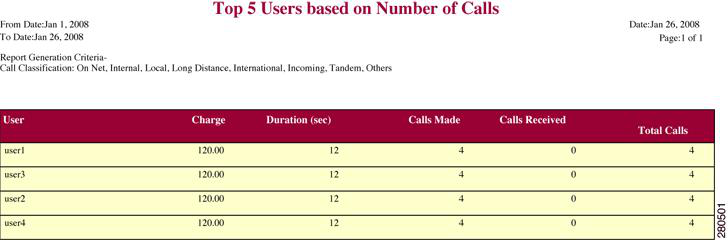
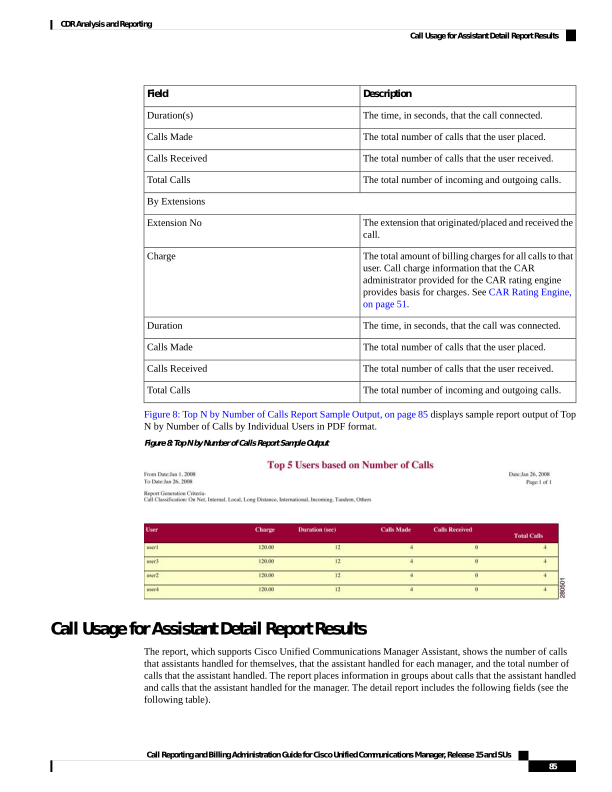
Page 98
Table 27: Detail Report Fields
Description
Field
The date that the call originated.
Date
The time that the call originated.
Orig. Time
The originating number from which the call was
placed.
Orig.
The destination number to which the call was directed.
Dest.
The type of call (internal, incoming, and so on).
Call Classification
The time, in seconds, that the call connected.
Duration (sec)
Figure 9: Call Usage for Assistant Detail Report, on page 86 displays sample output from a Call Usage for
the Assistant Detail report in PDF format.
Figure 9: Call Usage for Assistant Detail Report
Call Reporting and Billing Administration Guide for Cisco Unified Communications Manager, Release 15 and SUs
86
CDR Analysis and Reporting
Call Usage for Assistant Detail Report Results
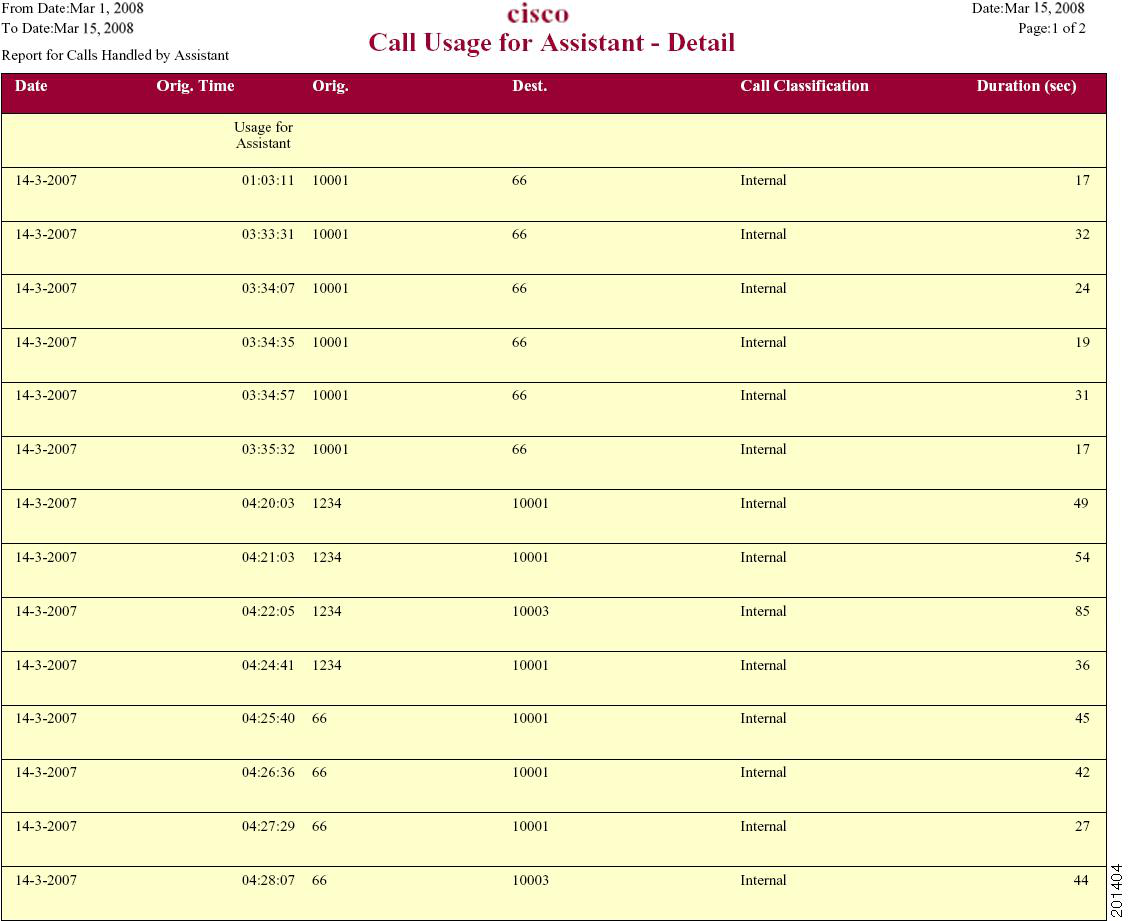
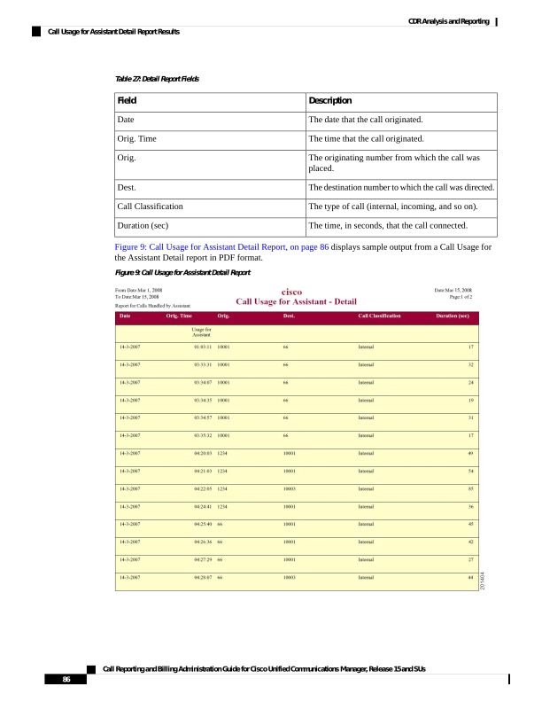
Page 99
Call Usage for Assistant Summary Report Results
The report, which supports Cisco Unified Communications Manager Assistant, shows information about calls
that the assistant handled for themselves and that the assistant handled for the manager. The reports place call
information by groups by attendant name. The summary report includes the following fields (see the following
table).
Table 28: Summary Report Fields
Description
Field
Shows the assistant name and directory number. If the assistant handles a call
for a manager, the manager name displays.
Assistant-Extn/Manager
Call Classification - Call categories specify classes.
Calls, including intracluster calls, that originate in the Unified Communications
Manager network and end in the same Unified Communications Manager network
(no gateways or trunks are used).
Internal
Local calls that are routed through the public switched telephone network (PSTN)
to numbers without an area code or that include one of the local area codes.
Local
Long-distance calls that originate in the Unified Communications Manager
network that go out through the PSTN.
Long Distance
International calls that originate in the Unified Communications Manager network
and go out through the PSTN.
International
Inbound calls that originate outside the Unified Communications
Managernetwork, enter through a gateway, and go into the Unified
Communications Manager network.
Incoming
Outgoing calls that originate on one Unified Communications Manager network,
go out through a trunk, and terminate on a different Unified Communications
Manager network. For CAR purposes, be aware that any outgoing call can be
classified as an OnNet call if it is configured as such in the CAR dial plan
configuration window. See Set Up Dial Plan, on page 31.
On Net
All other outgoing calls, such as toll-free numbers or emergency calls such as
911.
Others
The number of calls that the assistant handled or that the assistant handled for
the manager.
Calls
The total duration for all the calls for the particular call classification.
Duration (sec)
The following figure displays sample output of the Call Usage for the Assistant Summary report in PDF
format.
Call Reporting and Billing Administration Guide for Cisco Unified Communications Manager, Release 15 and SUs
87
CDR Analysis and Reporting
Call Usage for Assistant Summary Report Results
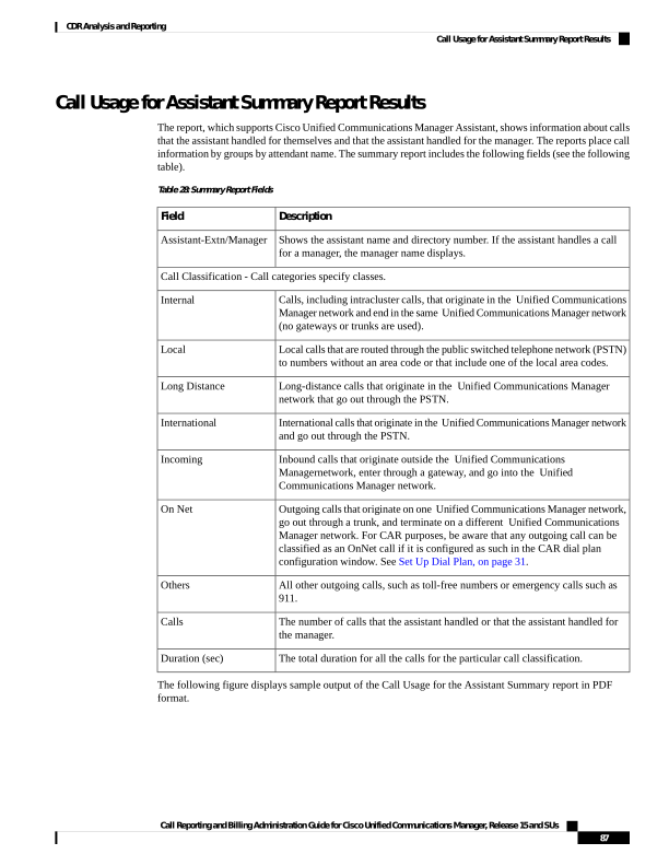
Page 100
Figure 10: Call Usage for Assistant Summary Report
Call Usage for Manager Detail Report Results
The report, which supports Cisco Unified Communications Manager Assistant, provides information about
calls that managers handle for themselves and that assistants handle for managers. The report places information
in groups by the assistant name and shows the total number of calls that the manager handles and that the
assistant handles for the manager. The detail report includes the following fields (see the table).
Table 29: Detail Report Fields
Description
Field
The date that the call originates.
Date
The time that the call originates.
Orig. Time
The originating number from which the call is placed.
Orig.
The destination number to which the call is directed.
Dest.
The type of call (internal, incoming, and so on).
Call Classification
The time, in seconds, that the call connects.
Duration (sec)
Figure 11: Call Usage for Manager Detail Report, on page 89 displays sample output from the Call Usage
for Manager Detail report.
Call Reporting and Billing Administration Guide for Cisco Unified Communications Manager, Release 15 and SUs
88
CDR Analysis and Reporting
Call Usage for Manager Detail Report Results
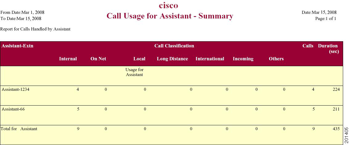
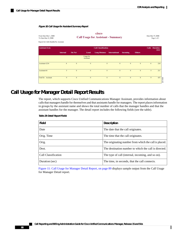
Page 101
Figure 11: Call Usage for Manager Detail Report
Call Usage for Manager Summary Report Results
The report, which supports Cisco Unified Communications Manager Assistant, shows information about calls
that the managers handle for themselves and that the assistants handle for the managers. The report places
information in groups by the manager name and shows the total number of calls that are handled for each
manager. The report includes the following fields (see the following table).
Table 30: Summary Report Fields
Description
Field
Shows the manager name and directory number. If the assistant handles a call
for a manager, the assistant name displays.
Manager-Extn/Assistant
Call Classification - Call categories specify classes.
Calls, including intracluster calls, that originate in the Unified Communications
Manager network and end in the same Unified Communications Managernetwork
(no gateways or trunks are used).
Internal
Local calls that are routed through the public switched telephone network (PSTN)
to numbers without an area code or that include one of the local area codes.
Local
Long-distance calls that originate in the Unified Communications Manager
network that go out through the PSTN.
Long Distance
International calls that originate in the Unified Communications Managernetwork
and go out through the PSTN.
International
Call Reporting and Billing Administration Guide for Cisco Unified Communications Manager, Release 15 and SUs
89
CDR Analysis and Reporting
Call Usage for Manager Summary Report Results
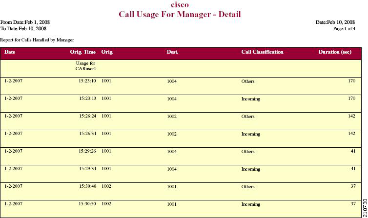
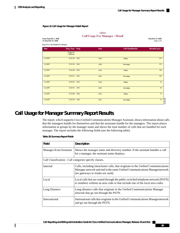
Page 102
Description
Field
Inbound calls that originate outside the Unified Communications Manager
network, enter through a gateway, and go into the Unified Communications
Manager network.
Incoming
Outgoing calls that originate on one Unified Communications Manager network,
go out through a trunk, and terminate on a different Unified Communications
Manager network. For CAR purposes, be aware that any outgoing call can be
classified as an OnNet call if it is configured as such in the CAR dial plan
configuration window. See Set Up Dial Plan, on page 31.
On Net
All other outgoing calls, such as toll-free numbers or emergency calls such as
911.
Others
The number of calls that the assistant or the manager handles.
Calls
The total duration for all the calls for the particular call classification.
Duration
The following figure displays sample output of the Call Usage for Manager Summary report in PDF format.
Figure 12: Call Usage for Manager Summary Report
IP Phone Services Report Results
The Cisco IP Phone Services report includes the following fields (see the table).
Table 31: CiscoUnifiedIPPhone Services Report Fields
Description
Field
The name of the selected service.
CiscoIPPhone Services
The total number of subscribers for a given service.
Number of Subscribers
Call Reporting and Billing Administration Guide for Cisco Unified Communications Manager, Release 15 and SUs
90
CDR Analysis and Reporting
IP Phone Services Report Results
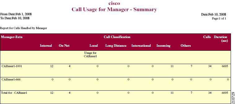
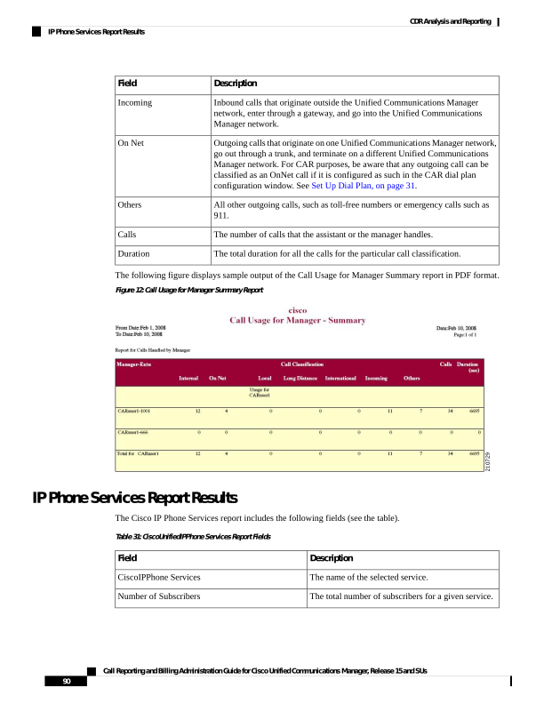
Page 103
Description
Field
The percentage of users who are subscribed to a given
service, out of the total number of subscriptions for
all services.
% Subscription
Figure 13: Cisco IP Phone Services Report Sample Output, on page 91 displays sample output from the Cisco
IP Phone Services Report in PDF format.
Figure 13: Cisco IP Phone Services Report Sample Output
Call Reporting and Billing Administration Guide for Cisco Unified Communications Manager, Release 15 and SUs
91
CDR Analysis and Reporting
IP Phone Services Report Results
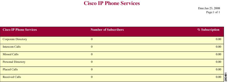
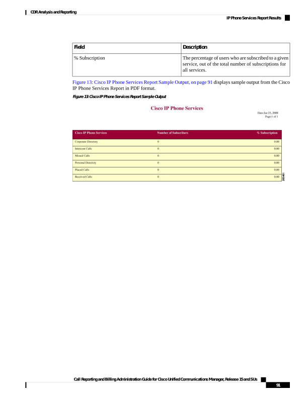
Page 104
Call Reporting and Billing Administration Guide for Cisco Unified Communications Manager, Release 15 and SUs
92
CDR Analysis and Reporting
IP Phone Services Report Results

Page 105
C H A P T E R 5
System Reports
• CAR System Reports, on page 93
• QoS System Reports, on page 96
• Traffic System Reports, on page 104
• FAC/CMC System Reports, on page 110
• Malicious Call Details System Reports, on page 112
• Precedence Call Summary System Reports, on page 113
• System Reports, on page 115
• CDR Error System Reports, on page 116
• System Reports Results, on page 119
CAR System Reports
CAR provides reporting capabilities for three levels of users:
• Administrators - Generate system reports to help with load balancing, system performance, and
troubleshooting.
• Managers - Generate reports for users, departments, and QoS to help with call monitoring for budgeting
or security purposes and for determining the voice quality of the calls.
• Individual users - Generate a billing report for calls of each user.
You may have access restrictions to view some reports depending on your job function.
Note
System Reports Summary Description
CDR Analysis and Reporting provide system reports for managers and CAR administrators. Managers or
CAR administrators can access the QoS summary report. Only CAR administrators can access all other reports.
This section describes the following reports:
• QoS
• Detail - Available for CAR administrators. The QoS detail report provides the QoS ratings that are
attributed to inbound and outbound calls on the Unified Communications Manager network for the
Call Reporting and Billing Administration Guide for Cisco Unified Communications Manager, Release 15 and SUs
93


Page 106
period that you specify. Use this report to help monitor the voice quality of all calls on a user-level
basis for the entire system. The call details in CDRs and CMRs and the QoS parameters that you
choose provide the basis for assigning a particular voice-quality category to a call.
• Summary - Available for managers and CAR administrators. This report provides a two-dimensional
pie chart that shows the distribution of QoS grades that are achieved for the specified call
classifications and period. The report also provides a table that summarizes the calls for each QoS.
The call details in CDRs and CMRs and the QoS parameters that you choose provide the basis for
assigning a call to a particular voice-quality category. Use this report to monitor the voice quality
of all calls through the network.
• By Gateway - Available for CAR administrators. This report shows the percentage of the calls for
each of the chosen gateways that meet the QoS criteria that the user chooses. You can generate this
report on an hourly, daily, or weekly basis.
• By Call Types - Available for CAR administrators. This report shows the percentage of the calls
for each chosen call type that meet the QoS criteria that the user chooses. You can generate this
report on an hourly, daily, or weekly basis.
• Traffic
• Summary - Available for CAR administrators. This report provides information about the call
volume for a period that you specify and include only those call types and QoS voice-quality
categories that you choose. Use this report to determine the number of calls that are being made on
an hourly, weekly, or daily basis. This report helps you identify high- and low-traffic patterns for
capacity planning.
• Summary by Phone Number - Available for CAR administrators. This report provides information
about the call volume for a period and set of phone numbers that you specify. It includes only those
call types and phone numbers that you choose. You can generate the report on an hourly, weekly,
or daily basis. This report helps you determine high-usage users or groups by aggregating the usage
level across the users that you specify.
• FAC/CMC
• Client Matter Code - Available for CAR administrators. This report allows administrators to view
the originating and destination numbers, the date, and time that the call originated, the call duration
in seconds, and the call classification for calls that relate to each chosen client matter code.
• Authorization Code Name - Available for CAR administrators. This report allows administrators
to view the originating and destination numbers, the date, and time that the call originated, the call
duration in seconds, the call classification, and the authorization level for calls that relate to each
chosen authorization code name.
• Authorization Level - Available for CAR administrators. This report allows administrators to view
the originating and destination numbers, the date, and time that the call originated, the call duration
in seconds, the authorization code name, and the call classification for calls that relate to each chosen
authorization level.
• Malicious Call Details - Available for CAR administrators. The Unified Communications Manager
Malicious Call Identification (MCID) service tracks malicious calls. The Malicious Call Details report
displays the details of malicious calls for a given date range.
• Precedence Call Summary - Available for CAR administrators. The Unified Communications ManagerCall
Precedence service allows authenticated users to preempt lower priority phone calls. The PDF version
Call Reporting and Billing Administration Guide for Cisco Unified Communications Manager, Release 15 and SUs
94
CDR Analysis and Reporting
System Reports Summary Description
Page 107
of the CAR Precedence Call Summary report displays the Call Summary for the precedence values in
the form of a bar chart, on an hour of the day, day of the week, or day of the month basis, for each of the
precedence levels that you choose. CAR generates one chart for each precedence level, a table for each
precedence level that lists the number of call legs, and a subtable that summarizes the percentage
distribution for each precedence level. CAR makes the report available on-demand; the report does not
get autogenerated.
• System Overview - Available for CAR administrators. Use the System Overview report to see a high-level
picture of the Unified Communications Manager network. The System Overview provides the following
reports:
• Top 5 Users Based on Charge
• Top 5 Destinations Based on Charge
• Top 5 Calls Based on Charge
• Top 5 Users Based on Duration
• Top 5 Destinations Based on Duration
• Top 5 Calls Based on Duration
• Traffic Summary Hour of Day - Incoming, Internal, International, Local, Long Distance, On Net,
Others, Tandem, and Total calls
• Traffic Summary Day of Week - Incoming, Internal, International, Local, Long Distance, On Net,
Others, Tandem, and Total calls
• Traffic Summary Day of Month - Incoming, Internal, International, Local, Long Distance, On Net,
Others, Tandem, and Total calls
• QoS Summary
• Gateway Summary
• CDR Error - Available for CAR administrators. This report provides statistics for the number of error
records in the CAR Billing_Error table and the reason for the errors. Use this report to determine whether
CAR incurred any errors with CDR data while the CDR data was loaded. This report lists the percentage
of CDRs that are invalid and the reason that these CDRs have been classified as invalid.
User Search
Many reports in CAR provide a search function, so you can look for users. The following CAR System reports
support search by user: QoS Details and Traffic Summary by Phone Number. You can mail all reports that
can be generated by using the Send Report button.
Before you begin
You must use the window in System Reports that allows you to search for users.
This section describes how to search for a user.
Call Reporting and Billing Administration Guide for Cisco Unified Communications Manager, Release 15 and SUs
95
CDR Analysis and Reporting
User Search
Page 108
Procedure
Step 1
Click the Search Users link.
A User Search window displays.
Step 2
In the First Name and Last Name fields, enter characters of the first or last name of the user and click Search.
A User Search Results window displays in the same window and lists all users who matched the search criteria
that you entered.
Step 3
In the row for the user that you want, click Select link.
The user that you chose gets added to the List of Users in the User Search window. Repeat this step to add
more users.
Step 4
When you have added all users, click Close in the User Search window.
QoS System Reports
CAR provides reporting capabilities for three levels of users:
• Administrators - Generate system reports to help with load balancing, system performance, and
troubleshooting.
• Managers - Generate reports for users, departments, and QoS to help with call monitoring for budgeting
or security purposes and for determining the voice quality of the calls.
• Individual users - Generate a billing report for calls by each user.
You may have access restrictions to view some reports depending on your job function.
Note
Only CAR administrators generate the QoS detail report. The report details the QoS ratings that are attributed
to inbound and outbound calls on the Unified Communications Manager network for the period that is specified.
Managers or CAR administrators generate the QoS summary report. The report provides a two-dimensional
pie chart that shows the distribution of QoS grades that are achieved for the specified call classifications and
period. The report also provides a table that summarizes the calls for each QoS. The call details in CDRs and
CMRs and the QoS parameters that are provided in the Define QoS Values, on page 54 provide a basis for
assigning a particular voice-quality category to a call.
You can either view reports that the system automatically generates or generate new reports. Only CAR
administrators can schedule reports for automatic generation. For more information, see Automatic Generation
of CAR Reports and Alerts, on page 55.
QoS Parameter Operators
The following table describes the QoS parameter operators that you use in generating the QoS reports.
Call Reporting and Billing Administration Guide for Cisco Unified Communications Manager, Release 15 and SUs
96
CDR Analysis and Reporting
QoS System Reports

Page 109
Table 32: QoS Parameter Operators
Description
Operator
Choose this operator to generate jitter, latency, or lost
packet data that is greater than or equal to the specified
value.
=
Choose this operator to generate jitter, latency, or lost
packet data that is equal to the specified value.
=
Choose this operator to generate jitter, latency, or lost
packet data that is less than or equal to the specified
value.
<=
Choose this operator to preclude jitter, latency, or lost
packet data.
N.A.
Choose this operator to generate jitter, latency, or lost
packet data that occurs between one value and another
value. When you choose this operator, a second field
displays, so you can set the start and end values.
Between
Generate QoS Detail Reports
This section describes how to generate, view, or mail detailed information about the system QoS.
Procedure
Step 1
Choose System Reports > QoS > Detail.
The QoS Detail window displays.
Step 2
In the Select Call Types area, check the check boxes for the types of calls that you want the report to include.
The following table describes the call types.
Table 33: QoS Detail Report Call Types
Description
Call Type
Outgoing calls that originate on one Unified Communications Manager network,
go out through a trunk and terminate on a different Unified Communications
Manager network. For CAR purposes, be aware that any outgoing call can be
classified as an OnNet call if it is configured as such in the CAR dial plan
configuration window. For more information, see Set Up Dial Plan, on page 31.
On Net
Calls, including intracluster calls, that originate in the Unified Communications
Manager network and end in the same Unified Communications Manager network
(no gateways or trunks are used).
Internal
Call Reporting and Billing Administration Guide for Cisco Unified Communications Manager, Release 15 and SUs
97
CDR Analysis and Reporting
Generate QoS Detail Reports
Page 110
Description
Call Type
Local calls that are routed through the public switched telephone network (PSTN)
to numbers without an area code or that include one of the local area codes.
Local
Long-distance calls that originate in the Unified Communications Manager
network and go out through the PSTN.
Long Distance
International calls that originate in the Unified Communications Manager network
and go out through the PSTN.
International
Inbound calls that originate outside the Unified Communications Manager
network, enter through a gateway and go into the Unified Communications
Manager network.
Incoming
Inbound calls that originate outside the Unified Communications Manager
network, enter the Unified Communications Manager network through a gateway
and are transferred outbound from the Unified Communications Manager network
through a gateway.
Tandem
All other outgoing calls, such as toll-free numbers or emergency calls such as
911.
Others
Step 3
In the Select QoS area, check the check boxes for the voice-quality categories that you want to be included
in the report. The parameters set in the following table provide the basis for all voice-quality categories.
Table 34: QoS Detail Report Voice Quality
Description
Voice Quality
QoS for these calls represents the highest possible quality.
Good
QoS for these calls, although slightly degraded, still fall within an acceptable
range.
Acceptable
Although QoS for these calls is degraded, calls still fall within a usable range.
Fair
QoS for these calls designates unsatisfactory quality.
Poor
These calls did not match any criteria for the established QoS categories.
NA
Step 4
Choose the date range for the period for which you want to see QoS information.
Step 5
In Select Users field, you can either choose all users or search for particular users. To choose all users, check
the Select All Users check box. To choose individual users, enter the user ID of the individual in the User ID
field and click Add .
Note
You can also use a provided search function. See the User Search, on page 95.
Step 6
Choose CSV in the Report Format area, if you want the report in CSV format. Choose PDF in the Report
Format area, if you want the report in PDF format.
Step 7
Click View Report.
Call Reporting and Billing Administration Guide for Cisco Unified Communications Manager, Release 15 and SUs
98
CDR Analysis and Reporting
Generate QoS Detail Reports
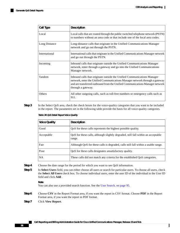
Page 111
Step 8
Click Send Report, if you want to mail the report. To send the report, perform the procedure that is described
in the Mail Reports, on page 63.
Generate QoS Summary Reports
This section describes how to generate, view, or mail summary information about the system QoS.
Procedure
Step 1
Perform one of the following steps:
a)
If you are a manager, choose QoS > Summary.
b) If you are a CAR administrator, choose System Reports > QoS > Summary.
The QoS Summary window displays.
Step 2
In the Available Reports field, choose an automatically generated report (if available) and go to the following
step, or use the default setting, Generate New Report, and go to the next step
Note
You can only choose the automatically generated report if you are logged in as a CAR administrator. The
automatically generated reports do not display in the drop-down list box if you are logged in as a manager.
Step 3
In the Select Call Types area, check the check boxes for the types of calls that you want the report to include.
The following table describes the call types.
Table 35: QoS Summary Report Call Types
Description
Call Type
Outgoing calls that originate on one Unified Communications Manager network,
go out through a trunk, and terminate on a different Unified Communications
Manager network. For CAR purposes, be aware that any outgoing call can be
classified as an OnNet call if it is configured as such in the CAR dial plan
configuration window. See Set Up Dial Plan, on page 31.
On Net
Calls, including intracluster calls, that originate in the Unified Communications
Manager network and end in the same Unified Communications Manager network
(no gateways or trunks are used).
Internal
Local calls that are routed through the public switched telephone network (PSTN)
to numbers without an area code or that include one of the local area codes.
Local
Long-distance calls that originate in the Unified Communications
Managernetwork and go out through the PSTN.
Long Distance
International calls that originate in the Unified Communications Manager network
and go out through the PSTN.
International
Call Reporting and Billing Administration Guide for Cisco Unified Communications Manager, Release 15 and SUs
99
CDR Analysis and Reporting
Generate QoS Summary Reports
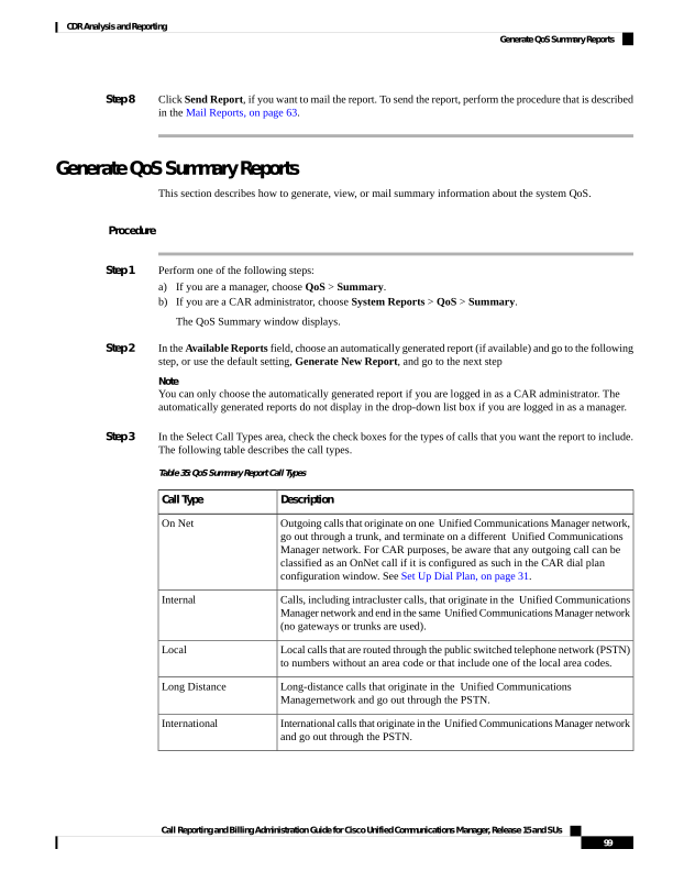
Page 112
Description
Call Type
Inbound calls that originate outside the Unified Communications
Managernetwork, enter through a gateway, and go into the Unified
Communications Managernetwork.
Incoming
Inbound calls that originate outside the Unified Communications Manager
network, enter the Unified Communications Managernetwork through a gateway,
and transfer outbound from the Unified Communications Manager network
through a gateway.
Tandem
All other outgoing calls, such as toll-free numbers or emergency calls such as
911.
Others
Step 4
If you chose Generate New Report in the previous step, choose the date range for the period for which you
want to generate the report.
Step 5
Choose CSV in the Report Format area, if you want the report in CSV format. Choose PDF in the Report
Format area, if you want the report in PDF format.
Step 6
Click View Report.
Step 7
Click Send Report, if you want to mail the report. To send the report, perform the procedure that is described
in the Mail Reports, on page 63.
Generate QoS by Gateway Reports
Only CAR administrators generate the QoS by Gateway report. The report provides the percentage of calls
that satisfy the selected QoS criteria for a period that is specified for the selected gateways.
Use CAR only during off-peak hours. Otherwise, data collection and report generation could cause performance
degradation on the Unified Communications Manager system.
Caution
This section describes how to generate, view, or mail QoS information about all chosen gateways.
Before you begin
Configure the gateway by using the procedures in the Set Up Gateway, on page 34.
Procedure
Step 1
Choose System Reports > QoS > By Gateways.
The QoS based on Gateways window displays.
Step 2
In the Generate Reports field, choose a time as described in the following table.
Call Reporting and Billing Administration Guide for Cisco Unified Communications Manager, Release 15 and SUs
100
CDR Analysis and Reporting
Generate QoS by Gateway Reports

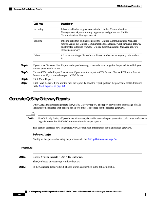
Page 113
Table 36: Generate Report Fields
Description
Parameter
Displays the percentage of the calls, for each selected
gateway, that satisfies the QoS criteria for the period
that you specify in Step 6, on page 101. The percentage
results show for an hour of the day.
Hour of Day
Displays the percentage of the calls, for each selected
gateway, that satisfies the QoS criteria for the period
that you specify in Step 6, on page 101. The percentage
results show for a day of the week.
Day of Week
Displays the percentage of the calls, for each selected
gateway, that satisfies the QoS criteria for the period
that you specify in Step 6, on page 101. The percentage
results show for day of month.
Day of Month
Step 3
In the Jitter field, choose the operator that you want to use and enter the value for jitter. See the Table 32:
QoS Parameter Operators, on page 97 for descriptions of operators.
Step 4
In the Latency field, choose the operator that you want to use and enter the value for latency. See the Table
32: QoS Parameter Operators, on page 97 for descriptions of operators.
Step 5
In the LostPackets field, choose the operator that you want to use and enter the value for a number of lost
packets. See the Table 32: QoS Parameter Operators, on page 97 for descriptions of operators.
Step 6
Choose the date range of the period for which you want to see call information.
Step 7
To choose the type of gateway that you want to be included in the report, perform one of the following tasks:
a)
To display all the gateways that are configured in the system, click Gateway Types in the column on
the left side of the window.
b) To expand the tree structure and display the type of gateway from which you can choose, click the icon
next to Gateway Types.
c)
To choose a gateway that uses a particular route pattern/hunt pilot, rather than a gateway type, click Route
Patterns/Hunt Pilots in the column on the left side of the window. The tree structure expands and displays
the gateways that are associated with the configured Route Patterns/Hunt Pilots.
d) To expand the tree structure and display route pattern/hunt pilot for you to choose, click the icon next to
Route Patterns/Hunt Pilots.
Note
You can also search for specific route patterns/hunt pilots by entering part of the name of the route
pattern(s)/hunt pilot(s) in the Route Patterns/Hunt Pilots box in the column on the left side of the window.
CAR searches for the route pattern(s)/hunt pilot(s) that matches the search string.
Step 8
From the list, choose a gateway type.
The gateway name displays in the List of Gateways box.
Note
The List of Gateways box display up to 200 gateways that are configured for the chosen gateway type.
Step 9
In the List of Gateways box, select the gateways that you want to include in the report.
Call Reporting and Billing Administration Guide for Cisco Unified Communications Manager, Release 15 and SUs
101
CDR Analysis and Reporting
Generate QoS by Gateway Reports
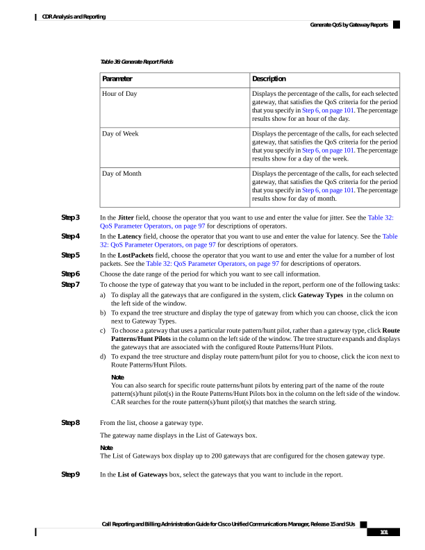
Page 114
Note
You can generate a report for up to 15 gateways at a time. If you select more than 15 gateways, you will see
the message “Select 15 or fewer gateways to generate a new report.”
Step 10
Click the down arrow icon to move the chosen gateway to the list of Selected Gateways box.
The gateway that you chose displays in the Selected Gateways box.
Step 11
Choose CSV in the Report Format area, if you want the report in CSV format. Choose PDF in the Report
Format area, if you want the report in PDF format.
Step 12
Click View Report.
Step 13
Click Send Report, if you want to mail the report. To send the report, perform the procedure that is described
in the Mail Reports, on page 63.
Generate QoS by Call Types Reports
Only CAR administrators generate the QoS by Call Types report. The report provides jitter, latency, and lost
packet information for a period that is specified for all calls of a chosen type.
This section describes how to generate, view, or mail QoS information about all calls of a certain type.
Use CAR only during off-peak hours. Otherwise, data collection and report generation could cause performance
degradation on the Unified Communications Manager system.
Caution
Procedure
Step 1
Choose System Reports > QoS > By Call Types.
The QoS based on Call Types window displays.
Step 2
In the Generate Report field, choose a time as described in the following table.
Table 37: Generate Report Fields
Description
Parameter
Displays the percentage of the calls, for each call type,
that satisfies the QoS criteria for the period that you
specify in Step 7, on page 104. The percentage results
show for an hour of the day.
Hour of Day
Displays the percentage of the calls, for each call type,
that satisfies the QoS criteria for the period that you
specify in Step 7, on page 104. The percentage results
show for a day of the week.
Day of Week
Call Reporting and Billing Administration Guide for Cisco Unified Communications Manager, Release 15 and SUs
102
CDR Analysis and Reporting
Generate QoS by Call Types Reports

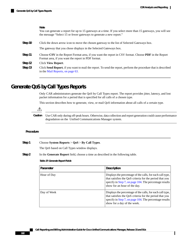
Page 115
Description
Parameter
Displays the percentage of the calls, for each call type,
that satisfies the QoS criteria for the period that you
specify in Step 7, on page 104. The percentage results
show for a day of the month.
Day of Month
Step 3
In the Jitter field, choose the operator that you want to use and enter the value for jitter. See the Table 32:
QoS Parameter Operators, on page 97 for descriptions of operators.
Step 4
In the Latency field, choose the operator that you want to use and enter the value for latency. See the Table
32: QoS Parameter Operators, on page 97 for descriptions of operators.
Step 5
In the LostPackets field, choose the operator that you want to use and enter the value for a number of lost
packets. See the Table 32: QoS Parameter Operators, on page 97 for descriptions of operators.
Step 6
In the Select Call Types area, check the check boxes for the types of calls that you want the report to include.
The following table describes the call types.
Table 38: QoS Parameters by Call Types
Description
Call Type
Outgoing calls that originate on one Unified
Communications Manager network, go out through
a trunk and terminate on a different Unified
Communications Manager network. For CAR
purposes, be aware that any outgoing call can be
classified as an OnNet call if it is configured as such
in the CAR dial plan configuration window. See Set
Up Dial Plan, on page 31.
On Net
Calls, including intracluster calls, that originate in the
Unified Communications Manager network and end
in the same Unified Communications Manager
network (no gateways or trunks are used).
Internal
Local calls that are routed through the public switched
telephone network (PSTN) to numbers without an
area code or that include one of the local area codes.
Local
Long-distance calls that originate in the Unified
Communications Manager network and go out through
the PSTN.
Long Distance
International calls that originate in the Unified
Communications Manager network and go out through
the PSTN.
International
Inbound calls that originate outside the Unified
Communications Manager network, enter through a
gateway and go into the Unified Communications
Manager network.
Incoming
Call Reporting and Billing Administration Guide for Cisco Unified Communications Manager, Release 15 and SUs
103
CDR Analysis and Reporting
Generate QoS by Call Types Reports
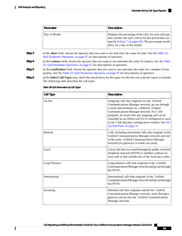
Page 116
Description
Call Type
Inbound calls that originate outside the Unified
Communications Manager network, enter the Unified
Communications Managernetwork through a gateway,
and transfer outbound from the Unified
Communications Manager network through a gateway.
Tandem
All other outgoing calls, such as toll-free numbers or
emergency calls such as 911.
Others
Step 7
Choose the date range for the period for which you want to see call information.
Step 8
Choose CSV in the Report Format area, if you want the report in CSV format. Choose PDF in the Report
Format area, if you want the report in PDF format.
Step 9
Click View Report.
Step 10
Click Send Report, if you want to mail the report. To send the report, perform the procedure that is described
in the Mail Reports, on page 63.
Traffic System Reports
CAR provides reporting capabilities for three levels of users:
• Administrators - Generate system reports to help with load balancing, system performance, and
troubleshooting.
• Managers - Generate reports for users, departments, and QoS to help with call monitoring for budgeting
or security purposes and for determining the voice quality of the calls.
• Individual users - Generate a billing report for calls by each user.
You may have access restrictions to view some reports depending on your job function.
Note
Only CAR administrators can generate the traffic summary report. The report provides information about the
call volume for a period that you specify. It includes only those call types and QoS voice-quality categories
that you chose.
When you configure CAR to generate a traffic summary report, you can choose different call types (On Net,
Internal, Local, Long Distance, and so on). CAR compares the traffic volume for every hour interval and
identifies the hour with the highest traffic volume (the Busy Hour Call Completion [BHCC] number). To
obtain the overall BHCC number, choose all call types when you configure CAR. Under the report title, a
separate line displays the BHCC number for that day.
Tip
Only CAR administrators can generate the traffic summary by phone numbers report. The report provides
information about the call volume for a period and set of phone numbers that you specify, and includes only
those call types and phone numbers that you choose.
Call Reporting and Billing Administration Guide for Cisco Unified Communications Manager, Release 15 and SUs
104
CDR Analysis and Reporting
Traffic System Reports


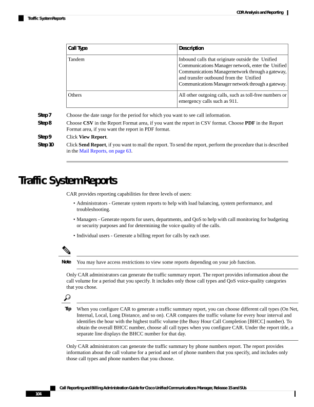
Page 117
You can use this report to track call usage by a specified group of users, by a department, or by another criteria,
such as lobby phones or conference room phones. You can set up this report to generate on a weekly basis.
This report helps you determine high-usage users or groups by aggregating the usage level across the users
that you specify.
Tip
Generate Traffic Summary Reports
Only CAR administrators generate the Traffic Summary report. The report provides information about the
call volume for a period that you specify.
You can either view reports that the system automatically generates or generate new reports. For more
information, see Set Up CDR Load Schedule, on page 36.
This section describes how to generate, view, or mail summary information about system traffic.
Procedure
Step 1
Choose System Reports > Traffic > Summary.
The Traffic Summary window displays.
Step 2
In the Generate Report field, choose a time as described in the following table.
Table 39: Generate Report Fields
Description
Parameter
Displays the average number of calls in the system
for the period that you specify in Step 4, on page 106,
the call types that you specify in Step 5, on page 106,
and the QoS values that you specify in Step 6, on page
107 for an hour of the day.
If the period that you specify in Step 4, on page 106
is within one day, the system compares the traffic
volume for every hour interval and identifies the hour
with the highest traffic volume as the BHCC number
for that day.
Hour of Day
Displays the average number of calls in the system
for the period that you specify in Step 4, on page 106,
the call types that you specify in Step 5, on page 106,
and the QoS values that you specify in Step 6, on page
107 for the day of the week.
Day of Week
Call Reporting and Billing Administration Guide for Cisco Unified Communications Manager, Release 15 and SUs
105
CDR Analysis and Reporting
Generate Traffic Summary Reports

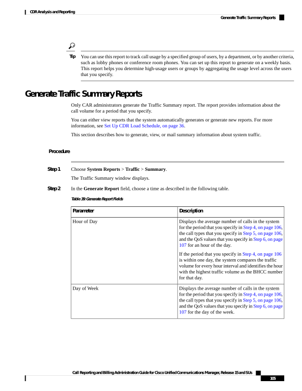
Page 118
Description
Parameter
Displays the average number of calls in the system
for the period that you specify in Step 4, on page 106,
the call types that you specify in Step 5, on page 106,
and the QoS values that you specify in Step 6, on page
107 for a day of the month.
Day of Month
Step 3
In the Available Reports field, choose an automatically generated report (if available) and go to Step 8, on
page 107 or use the default setting, Generate New Report and go to Step 4, on page 106.
Step 4
Choose the date range for the period for which you want to generate the report.
Step 5
In the Select Call Types area, check the check boxes for the types of calls that you want to include in the
report. To obtain the overall BHCC number for a particular hour or 24-hour period, choose all call types. The
following table describes the call types.
Table 40: Traffic Summary by Call Types
Description
Call Type
Outgoing calls that originate on one Unified
Communications Manager network, go out through
a trunk and terminate on a different Unified
Communications Manager network. For CAR
purposes, be aware that any outgoing call can be
classified as an OnNet call if it is configured as such
in the CAR dial plan configuration window. See Set
Up Dial Plan, on page 31.
On Net
Calls, including intracluster calls, that originate in the
Unified Communications Manager network and end
in the same Unified Communications Manager
network (no gateways or trunks are used).
Internal
Local calls that route through the public switched
telephone network (PSTN) to numbers without an
area code or that include one of the local area codes.
Local
Long-distance calls that originate in the Unified
Communications Manager network and go out through
the PSTN.
Long Distance
International calls that originate in the Unified
Communications Manager network and go out through
the PSTN.
International
Inbound calls that originate outside the Unified
Communications Manager network, enter through a
gateway and go into the Unified Communications
Manager network.
Incoming
All other outgoing calls, such as toll-free numbers or
emergency calls such as 911.
Others
Call Reporting and Billing Administration Guide for Cisco Unified Communications Manager, Release 15 and SUs
106
CDR Analysis and Reporting
Generate Traffic Summary Reports
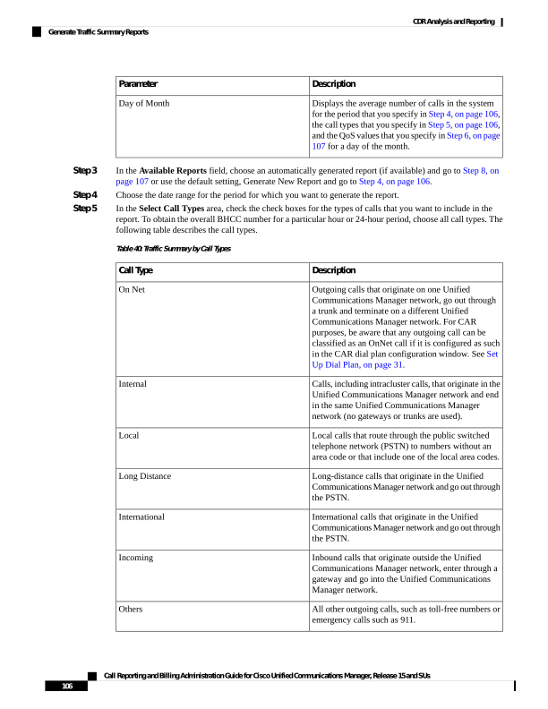
Page 119
Note
The calls that the chart/table shows comprise an average number of calls per day. If the data that is generated
is less and you have chosen a wide date range, the report shows negligible values that are treated as 0, and
the graph does not display. For example, if a Day of Week report gets generated for eight days that comprise
two Mondays, the data that is shown for Monday represents the average number of calls for both the Mondays
(the sum of all the calls in each Monday that is divided by 2). Similarly, in an Hour of Day report, the data
that displays against 05-06 will designate the average number of calls per day between the time 05 and 06 of
the date range that was chosen for the report.
Step 6
In the Select QoS area, check the check boxes for the voice-quality categories that you want to include in the
report. The parameters that are set in the following table provide the basis for all voice-quality categories.
Table 41: QoS Detail Report Voice Quality
Description
Voice Quality
QoS for these calls represents the highest possible
quality.
Good
QoS for these calls, although slightly degraded, still
falls within an acceptable range.
Acceptable
QoS for these calls, although degraded, remains within
a usable range.
Fair
Poor voice quality indicates that QoS for these calls
is unsatisfactory.
Poor
These calls did not match any criteria for the
established QoS categories.
NA
Step 7
Choose CSV in the Report Format area, if you want the report in CSV format. Choose PDF in the Report
Format area, if you want the report in PDF format.
Step 8
Click View Report.
Step 9
Click Send Report, if you want to mail the report. To send the report, perform the procedure that is described
in the Mail Reports, on page 63.
Generate Traffic Summary by Phone Number Reports
Only CAR administrators generate the Traffic Summary by Phone Number report. The report provides
information about the call volume for a period and set of phone numbers that you specify.
This section describes how to generate, view, or mail a traffic summary report based on user phone numbers.
Procedure
Step 1
Choose System Reports > Traffic > Summary By Phone Number.
The Traffic Summary that is based on Phone Number(s) window displays.
Call Reporting and Billing Administration Guide for Cisco Unified Communications Manager, Release 15 and SUs
107
CDR Analysis and Reporting
Generate Traffic Summary by Phone Number Reports
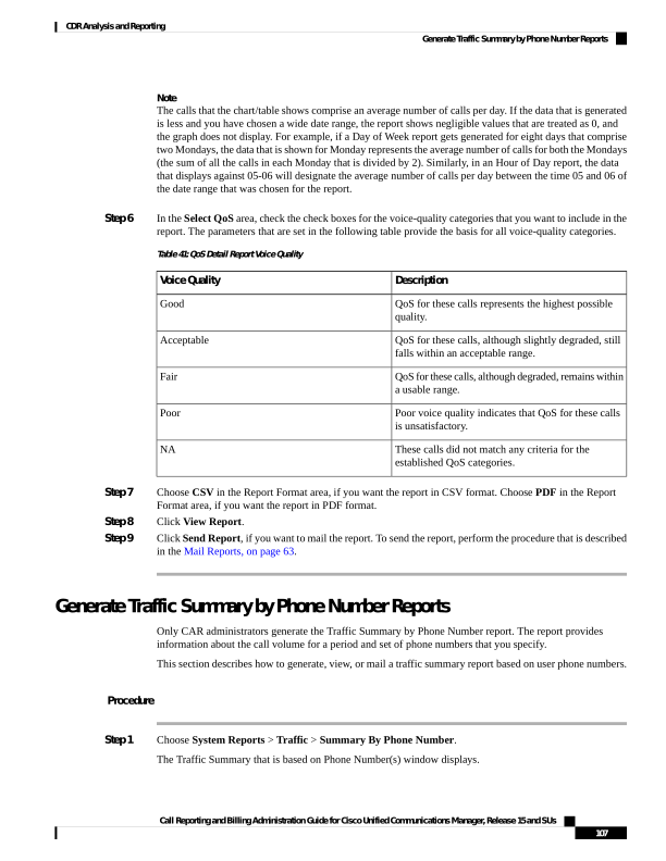
Page 120
Step 2
In the Generate Report field, choose a time as described in the following table.
Table 42: Generate Report Fields
Description
Parameter
Displays the average number of calls in the system
for the chosen phone numbers for the date range that
was chosen for an hour of the day.
Note
Ensure that the date and time range does not exceed
one month.
Hour of Day
Displays the average calls in the system for the
selected phone numbers for the date range that was
chosen for the day of the week.
Note
Ensure that the date and time range does not exceed
one month.
Day of Week
Displays the average calls in the system for the
selected phone numbers for the date range that was
chosen for the day of the month.
Note
Ensure that the date and time range does not exceed
one month.
Day of Month
Step 3
In the Select Call Types area, check the check boxes for the types of calls that you want to include in the
report. The following table describes the call types.
Table 43: Traffic Summary (Phone Number) by Call Types
Description
Call Type
Outgoing calls that originate on one Unified
Communications Manager network, go out through
a trunk, and terminate on a different Unified
Communications Manager network. For CAR
purposes, be aware that any outgoing call can be
classified as an OnNet call if it is configured as such
in the CAR dial plan configuration window. See Set
Up Dial Plan, on page 31.
On Net
Calls, including intracluster calls, that originate in the
Unified Communications Manager network and end
in the same Unified Communications Manager
network (no gateways or trunks are used).
Internal
Call Reporting and Billing Administration Guide for Cisco Unified Communications Manager, Release 15 and SUs
108
CDR Analysis and Reporting
Generate Traffic Summary by Phone Number Reports
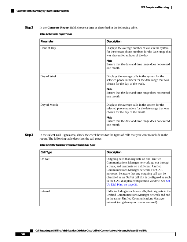
Page 121
Description
Call Type
Local calls that are routed through the public switched
telephone network (PSTN) to numbers without an
area code or that include one of the local area codes.
Local
Long-distance calls that originate in the Unified
Communications Manager network and go out through
the PSTN.
Long Distance
International calls that originate in the Unified
Communications Manager network and go out through
the PSTN.
International
Inbound calls that originate outside the Unified
Communications Manager network, enter through a
gateway and go into the Unified Communications
Manager network.
Incoming
All other outgoing calls, such as toll-free numbers or
emergency calls such as 911.
Others
Note
The calls that the chart/table shows comprise an average number of calls per day. If the data that is generated
is less and you have chosen a wide date range, the report shows negligible values that are treated as 0, and
the graph does not display. For example, if a Day of Week report gets generated for eight days that comprise
two Mondays, the data that is shown for Monday represents the average number of calls for both the Mondays
(the sum of all the calls in each Monday that is divided by 2). Similarly, in an Hour of Day report, the data
that displays against 05-06 will represent the average number of calls per day between the time 05 and 06 of
the date range that was chosen for the report.
Step 4
In the Select Phone Number(s) group box, you can either choose all phone numbers or search for phone
numbers based on users.
Note
You can enter a wildcard pattern like "!" or "X" to search on phone numbers. The "!" represents any n digit
that has 0-9 as each of its digits, and the "X" represents a single digit in the range 0-9.
To choose all phone numbers, check the Select All Phone Number(s) check box. To choose phone numbers
based on users, enter the phone number of the individual in the Phone Number field and click the Add Phone
Number button. You can also use a provided search function, as described in the User Search, on page 95.
Step 5
Choose CSV in the Report Format area, if you want the report in CSV format. Choose PDF in the Report
Format area, if you want the report in PDF format.
Step 6
Click View Report.
Step 7
Click Send Report, if you want to mail the report. To send the report, perform the procedure that is described
in the Mail Reports, on page 63.
Call Reporting and Billing Administration Guide for Cisco Unified Communications Manager, Release 15 and SUs
109
CDR Analysis and Reporting
Generate Traffic Summary by Phone Number Reports
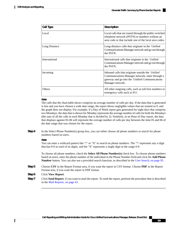
Page 122
FAC/CMC System Reports
CAR provides reporting capabilities for three levels of users:
• Administrators - Generate system reports to help with load balancing, system performance, and
troubleshooting.
• Managers - Generate reports for users, departments, and QoS to help with call monitoring for budgeting
or security purposes and for determining the voice quality of the calls.
• Individual users - Generate a billing report for calls by each user.
You may have access restrictions to view some reports depending on your job function.
Note
Only CAR administrators can generate Forced Authorization Code (FAC)/Client Matter Code (CMC) reports.
The following sections describe how to configure FAC/CMC reports:
Generate Client Matter Code Reports
Only CAR administrators can generate the Client Matter Code report. You can generate a report that shows
the origination (calling number), destination (called number), origination date time (the date and time that the
call originated), duration (call duration in seconds), and the call classification that relates to each CMC.
The following procedure describes how to generate a report that shows the usage of specific client matter
codes.
Procedure
Step 1
Choose System Reports > FAC/CMC > Client Matter Code.
The Call Details for Client Matter Code window displays a list of all client matter codes that are configured
in the system.
Step 2
In the List of Client Matter Codes box, choose the codes that you want to be included in the report.
Note
You can choose up to 100 Client Matter Codes.
Step 3
To add the chosen code(s) to the Selected Client Matter Codes box, click down arrow.
The report includes all codes, for which data is available, that are listed in this box.
Step 4
In the From Date and To Date pull-down list boxes, enter the date range of the period for which you want
to see Client Matter Code information.
Step 5
Choose CSV in the Report Format area, if you want the report in CSV format. Choose PDF in the Report
Format area, if you want the report in PDF format.
Step 6
Click View Report.
Call Reporting and Billing Administration Guide for Cisco Unified Communications Manager, Release 15 and SUs
110
CDR Analysis and Reporting
FAC/CMC System Reports

Page 123
Step 7
Click Send Report, if you want to mail the report. To send the report, perform the procedure that is described
in Mail Reports, on page 63.
Generate Authorization Code Name Reports
Only CAR administrators can generate the Authorization Code Name report. You can generate a report that
shows the origination (calling number), destination (called number), origination date time (the date and time
that the call originated), duration (call duration in seconds), and the call classification that relates to each
chosen authorization code name.
For security purposes, the authorization code does not display; instead, the authorization code name (description)
displays.
Note
The following procedure describes how to generate a report that shows the usage of specific authorization
code names.
Procedure
Step 1
Choose System Reports > FAC/CMC > Authorization Code Name.
The Call Details for Authorization Code Name window displays a list of all authorization code names that
are configured in the system.
Step 2
In the List of Authorization Code Names box, choose the code names that you want to be included in the
report.
Note
You can choose up to 30 code names.
Step 3
To add the chosen code name(s) to the Selected Authorization Code Names box, click the down arrow.
The report includes all code names, for which data is available, that are listed in this box.
Step 4
In the From Date and To Date drop-down list boxes, enter the date range of the period for which you want
to see authorization code name information.
Step 5
Choose CSV in the Report Format area, if you want the report in CSV format. Choose PDF in the Report
Format area, if you want the report in PDF format.
Step 6
Click View Report.
Step 7
Click Send Report, if you want to mail the report. To send the report, perform the procedure that is described
in Mail Reports, on page 63.
Call Reporting and Billing Administration Guide for Cisco Unified Communications Manager, Release 15 and SUs
111
CDR Analysis and Reporting
Generate Authorization Code Name Reports

Page 124
Generate Authorization Level Reports
Only CAR administrators can generate the Authorization Level report. You can generate a report that shows
the origination (calling number), destination (called number), origination date time (the date and time that the
call originated), duration (call duration in seconds), and the call classification that relate to each chosen
authorization level.
The following procedure describes how to generate a report that shows the usage of specific authorization
levels.
Procedure
Step 1
Choose System Reports > FAC/CMC > Authorization Level.
The Call Details by Authorization Level window displays a list of all authorization levels that are configured
in the system.
Step 2
In the List of Authorization Levels box, choose the levels that you want to be included in the report.
Step 3
To add the chosen level(s) to the Selected Authorization Levels box, click the down arrow.
The report includes all levels, for which data is available, that are listed in this box.
Note
Only FAC authorization levels reports that are associated with Route Patterns will get generated.
Step 4
In the From Date and To Date drop-down list boxes, enter the date range of the period for which you want
to see authorization level information.
Step 5
Choose CSV in the Report Format area, if you want the report in CSV format. Choose PDF in the Report
Format area, if you want the report in PDF format.
Step 6
Click View Report.
Step 7
Click Send Report, if you want to mail the report. To send the report, perform the procedure that is described
in the Mail Reports, on page 63.
Malicious Call Details System Reports
CAR provides reporting capabilities for three levels of users:
• Administrators - Generate system reports to help with load balancing, system performance, and
troubleshooting.
• Managers - Generate reports for users, departments, and QoS to help with call monitoring for budgeting
or security purposes and for determining the voice quality of the calls.
• Individual users - Generate a billing report for calls by each user.
You may have access restrictions to view some reports depending on your job function.
Note
Call Reporting and Billing Administration Guide for Cisco Unified Communications Manager, Release 15 and SUs
112
CDR Analysis and Reporting
Generate Authorization Level Reports

Page 125
Generate Malicious Call Details Reports
Only CAR administrators generate the Malicious Call Details report. The report displays the following details
about malicious calls for a particular date range: origination time, termination time, duration (in seconds),
origination (calling number), destination (called number), origination device, destination device, and call
classification.
This section describes how to generate, view, or mail a Malicious Call Detail report.
Procedure
Step 1
Choose System Reports > Malicious Call Details.
The Malicious Call Details window displays.
Step 2
In the From Date drop-down list boxes, choose the month, day, and year from which you want malicious
call details.
Step 3
In the To Date drop-down list boxes, choose the month, day, and year to which you want malicious call
details.
Step 4
Choose CSV in the Report Format area, if you want the report in CSV format. Choose PDF in the Report
Format area, if you want the report in PDF format.
Step 5
To view the report, click View Report.
Step 6
To mail the report to an email recipient, see the Mail Reports, on page 63.
Precedence Call Summary System Reports
CAR provides reporting capabilities for three levels of users:
• Administrators - Generate system reports to help with load balancing, system performance, and
troubleshooting.
• Managers - Generate reports for users, departments, and QoS to help with call monitoring for budgeting
or security purposes and for determining the voice quality of the calls.
• Individual users - Generate a billing report for calls by each user.
You may have access restrictions to view some reports depending on your job function.
Note
Generate Precedence Call Summary Reports
Only CAR administrators generate the Call Summary by Precedence report. The report displays the Call
Summary for the precedence values that you choose by Hour of Day, Day of Week, or Day of Month.
This section describes how to generate, view, or mail a Call Summary by Precedence report.
Call Reporting and Billing Administration Guide for Cisco Unified Communications Manager, Release 15 and SUs
113
CDR Analysis and Reporting
Generate Malicious Call Details Reports

Page 126
Procedure
Step 1
Choose System Reports > Precedence Call Summary.
The Call Summary by Precedence window displays.
Step 2
In the Generate Reports field, choose a time as described in the following table.
Table 44: Generate Report Fields
Description
Parameter
Displays the average number of calls in the system
for the chosen phone numbers for the date range that
was chosen for an hour of the day.
Note
Ensure that the date and time range does not exceed
one month.
Hour of Day
Displays the average number of calls in the system
for the chosen phone numbers for the date range that
was chosen for the day of the week.
Note
Ensure that the date and time range does not exceed
one month.
Day of Week
Displays the average number of calls in the system
for the chosen phone numbers for the date range that
was chosen for the day of the month.
Note
Ensure that the date and time range does not exceed
one month.
Day of Month
Step 3
In the Select Precedence Levels field, check a precedence level that you want in the report or click Select
All to check all precedence levels.
Table 45: Call Precedence Levels
Description
Voice Quality
Highest precedence setting for MLPP calls.
Flash Override
Second highest precedence setting for MLPP calls.
Flash
Third highest precedence setting for MLPP calls.
Immediate
Fourth highest precedence setting for MLPP calls.
Priority
Lowest precedence setting for MLPP calls.
Routine
Call Reporting and Billing Administration Guide for Cisco Unified Communications Manager, Release 15 and SUs
114
CDR Analysis and Reporting
Generate Precedence Call Summary Reports
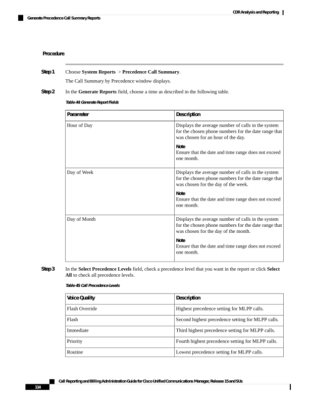
Page 127
Note
The Executive Override precedence level that is mentioned in the MLPP Precedence level on the Administration
page will be considered as Flash Override in this report.
Note
To uncheck the precedence level check boxes, click Clear All.
Step 4
In the From Date drop-down list boxes, choose the month, day, and year from which you want precedence
summary information.
Step 5
In the To Date drop-down list boxes, choose the month, day, and year for which you want precedence summary
information.
Step 6
Choose CSV in the Report Format area, if you want the report in CSV format. Choose PDF in the Report
Format area, if you want the report in PDF format.
Step 7
Click View Report.
Step 8
To mail the report to an e-mail recipient, see the Mail Reports, on page 63.
System Reports
CAR provides reporting capabilities for three levels of users:
• Administrators - Generate system reports to help with load balancing, system performance, and
troubleshooting.
• Managers - Generate reports for users, departments, and QoS to help with call monitoring for budgeting
or security purposes and for determining the voice quality of the calls.
• Individual users - Generate a billing report for each call by each user.
You may have access restrictions to view some reports depending on your job function.
Note
Generate System Reports
Only CAR administrators generate the System Overview report that provides the entire set of system reports
in one report.
The System Overview report includes the following information:
• Top five users based on charge.
• Top five destinations based on charge.
• Top five calls based on charge.
• Top five users based on duration.
• Top five destinations based on duration.
• Top five calls based on duration.
Call Reporting and Billing Administration Guide for Cisco Unified Communications Manager, Release 15 and SUs
115
CDR Analysis and Reporting
System Reports

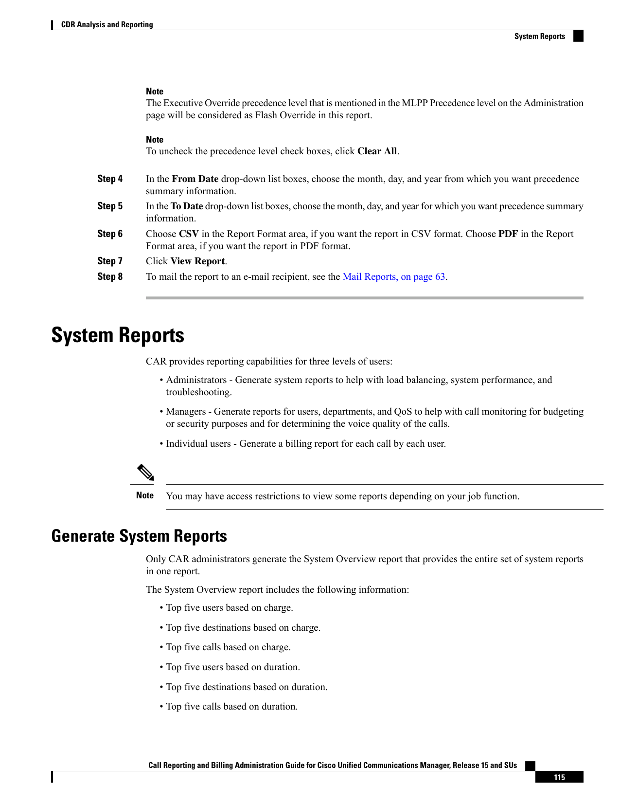
Page 128
• Traffic summary - Hour of day for incoming, internal, international, local, long distance, on the net,
others, tandem, and total calls.
• Traffic summary - Day of the week for incoming, internal, international, local, long distance, on the net,
others, tandem, and total calls.
• Traffic summary - Day of month for incoming, internal, international, local, long distance, on the net,
others, tandem, and total calls.
• Quality of service summary.
• Gateway summary.
For more information about the System Overview reports, see the System Reports Results, on page 119.
You can either view reports that the system automatically generates or generate new reports. Only CAR
administrators can schedule reports for automatic generation. For more information, see Set Up CDR Load
Schedule, on page 36.
This section describes how to generate, view, or mail summary information about the Unified Communications
Manager system.
Procedure
Step 1
Choose System Reports > System Overview.
The System Overview window displays.
Step 2
In the Available Reports field, select an automatically generated report (if available) and go to Step 6, on
page 116, or use the default setting, Generate New Report, and go to Step 3, on page 116.
Step 3
Choose the date range for the period for which you want to generate the report.
Step 4
From the List of Reports, select the reports that you want to be generated by highlighting the report and
clicking the right arrow.
The reports that you select appear in the Selected Reports list box.
Tip
You can highlight more than one report at a time by pressing the Ctrl key on your keyboard while clicking
the reports.
Step 5
Choose CSV in the Report Format area, if you want the report in CSV format. Choose PDF in the Report
Format area, if you want the report in PDF format.
Step 6
Click View Report.
Step 7
Click Send Report, if you want to mail the report. To send the report, perform the procedure that is described
in Mail Reports, on page 63.
CDR Error System Reports
CAR provides reporting capabilities for three levels of users:
Call Reporting and Billing Administration Guide for Cisco Unified Communications Manager, Release 15 and SUs
116
CDR Analysis and Reporting
CDR Error System Reports
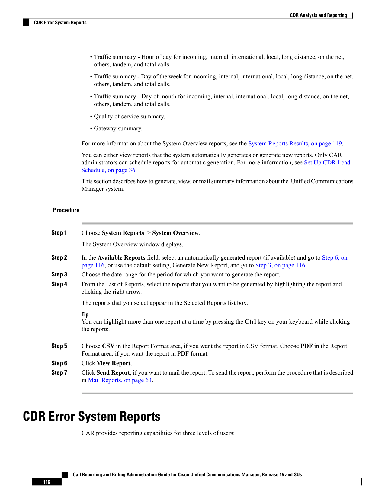
Page 129
• Administrators - Generate system reports to help with load balancing, system performance, and
troubleshooting.
• Managers - Generate reports for users, departments, and QoS to help with call monitoring for budgeting
or security purposes and for determining the voice quality of the calls.
• Individual users - Generate a billing report for calls by each user.
You may have access restrictions to view some reports depending on your job function.
Note
Generate CDR Error Reports
Only CAR administrators generate the CDR Error report. The report provides statistics for the number of
error records in the CAR Billing Error (tbl_billing_error) table for a particular time period.
In order to determine why the error records failed the CDR Load, you must review the information in the
tbl_error_id_map table.
The following table lists the CDR error codes and the definition of the error.
Table 46: CDR Error Codes
Definition
Error Code
CDRs
CDR globalCallID_callManagerId <= 0
31101
CDR globalCallID_callId <= 0
31102
CDR origLegCallIdentifier <= 0
31103
CDR dateTimeOrigination <= 0
31105
CDR destLegIdentifier <= 0
31108
CDR dateTimeConnect <= 0
31110
CDR dateTimeDisconnect <= 0
31111
CDR originalCalledPartyNumber is empty
31119
CDR finalCalledPartyNumber is empty
31120
CDR duration < 0
31122
CDR LDAP error while retrieving UserID or
ManagerID
31137
CDR callingPartyNumber is empty
31139
CDR origDeviceName is empty
31147
Call Reporting and Billing Administration Guide for Cisco Unified Communications Manager, Release 15 and SUs
117
CDR Analysis and Reporting
Generate CDR Error Reports

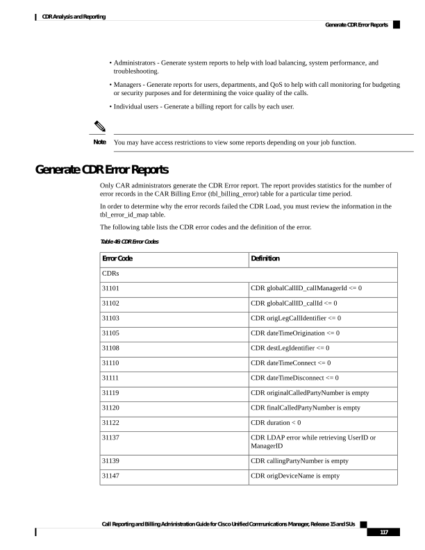
Page 130
Definition
Error Code
CDR destDeviceName is empty
31148
CDR origCallTerminationOnBehalfOf < 0
31151
CDR destCallTerminationOnBehalfOf < 0
31152
CDR lastRedirectRedirectOnBehalfOf < 0
31153
CDR destConversationId < 0
31155
CDR globalCallId_ClusterID is empty
31156
Orig CMR
Orig CMR globalCallID_callManagerId <= 0
31123
Orig CMR globalCallID_callId <= 0
31124
Orig CMR numberPacketsSent < 0
31125
Orig CMR numberPacketsReceived < 0
31126
Orig CMR jitter < 0
31127
Orig CMR callIdentifier <= 0
31129
Orig CMR deviceName is empty
31149
Orig CMR globalCallId_ClusterID is empty
31157
Dest CMR
Dest CMR globalCallID_callManagerId <= 0
31140
Dest CMR globalCallID_callId <= 0
31141
Dest CMR numberPacketsSent < 0
31142
Dest CMR numberPacketsReceived < 0
31143
Dest CMR jitter < 0
31144
Dest CMR callIdentifier <= 0
31145
Dest CMR deviceName is empty
31150
Dest CMR globalCallId_ClusterID is empty
31158
This section describes how to generate, view, or mail information about the CDR Error report.
Call Reporting and Billing Administration Guide for Cisco Unified Communications Manager, Release 15 and SUs
118
CDR Analysis and Reporting
Generate CDR Error Reports
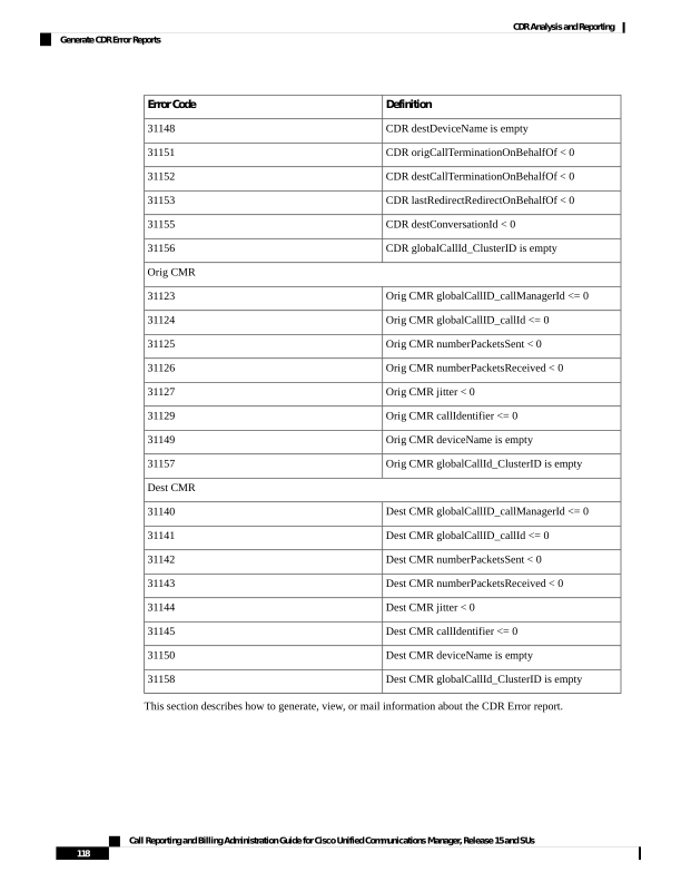
Page 131
Procedure
Step 1
Choose System Reports > CDR Error.
The CDR Error window displays.
Step 2
Choose the date range of the period for which you want to generate the report.
Step 3
Choose CSV in the Report Format area, if you want the report in CSV format. Choose PDF in the Report
Format area, if you want the report in PDF format.
Step 4
Click View Report.
Step 5
Click Send Report, if you want to mail the report. To send the report, perform the procedure that is described
in the Mail Reports, on page 63.
System Reports Results
This chapter describes report output information for each CAR system report.
QoS Detail Report Results
The results of the QoS Detail report include the following fields. See the following table.
Table 47: QoS Detail Report Fields
Description
Field
The time that the call was placed, in 24-hour, minute,
and second format.
Orig. Time
The time that the call disconnected, in 24 hour,
minute, and second format.
Term. Time
The time, in seconds, that the call was connected.
Duration(s)
The originating number from which the call was
placed.
Orig.
The destination number to which the call was directed.
Dest.
Call Classification - Call categories specify classes.
Call Reporting and Billing Administration Guide for Cisco Unified Communications Manager, Release 15 and SUs
119
CDR Analysis and Reporting
System Reports Results
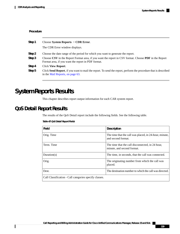
Page 132
Description
Field
Outgoing calls that originate on one Unified
Communications Manager network, go out through
a trunk, and terminate on a different Unified
Communications Manager network. For CAR
purposes, be aware that any outgoing call can be
classified as an OnNet call if it is configured as such
in the CAR dial plan configuration window. See Set
Up Dial Plan, on page 31.
On Net
Calls, including intracluster calls, that originate in the
Unified Communications Manager network and end
in the same Unified Communications
Managernetwork (no gateways or trunks are used).
Internal
Local calls that are routed through the public switched
telephone network (PSTN) to numbers without an
area code or that include one of the local area codes.
Local
Long-distance calls that originate in the Unified
Communications Manager network and go out through
the PSTN.
Long Distance
International calls that originate in the Unified
Communications Managernetwork that go out through
the PSTN.
International
Inbound calls that originate outside the Unified
Communications Manager network, enter through a
gateway, and go into the Unified Communications
Manager network.
Incoming
Inbound calls that originate outside the Unified
Communications Managernetwork, enter the Unified
Communications Managernetwork through a gateway,
and are transferred outbound from the Unified
Communications Manager network through a gateway.
Tandem
All other outgoing calls, such as toll-free numbers or
emergency calls such as 911.
Others
The codec that the originating device uses.
Orig. Codec
The codec that the destination device uses.
Dest. Codec
The name of the device that placed the call.
Orig. Device
The name of the device that received the call.
Dest. Device
The voice quality that the device that placed the call
experienced.
Orig. QoS
Call Reporting and Billing Administration Guide for Cisco Unified Communications Manager, Release 15 and SUs
120
CDR Analysis and Reporting
QoS Detail Report Results
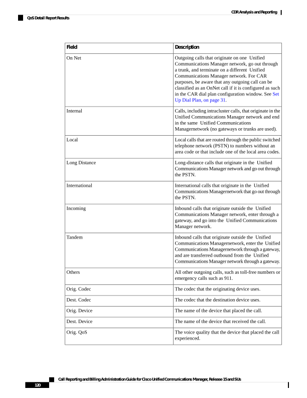
Page 133
Description
Field
The voice quality that the device that received the call
experienced.
Dest. QoS
The following figure displays sample output of the QoS Detail report in PDF format.
Figure 14: QoS Detail Report
QoS Summary Report Results
The QoS Summary report includes the following fields. See the table. If you select PDF format for the report
output, the report shows a pie chart that displays the QoS of the total number of calls.
Table 48: QoS Summary Report Fields
Description
Field
The quality of service of the calls.
Quality of Service
Number of call legs with the quality of service that
the Quality of Service field specified.
Call Legs
Figure 15: QoS Summary Report in PDF Format, on page 122 displays sample output of the QoS Summary
Report in PDF format.
Call Reporting and Billing Administration Guide for Cisco Unified Communications Manager, Release 15 and SUs
121
CDR Analysis and Reporting
QoS Summary Report Results
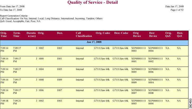
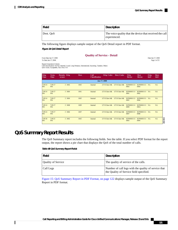
Page 134
Figure 15: QoS Summary Report in PDF Format
QoS by Gateways Report Results
The QoS by Gateways report provides the following information. See the table.
Table 49: QoS by Gateways Report Fields
Description
Field
Indicates the cumulative hours of the day(s), the days
of the week, or the days of the month for the selected
date range.
Time/Day
Displays the percentage of calls for each gateway for
the hours of the day, the days of the week, or the days
of the month for the selected date range.
% of Call Legs
Figure 16: QoS by Gateways Report, on page 123 displays sample output of the QoS by Gateways report in
PDF format.
Call Reporting and Billing Administration Guide for Cisco Unified Communications Manager, Release 15 and SUs
122
CDR Analysis and Reporting
QoS by Gateways Report Results
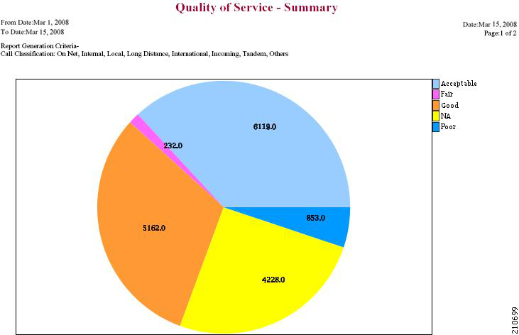
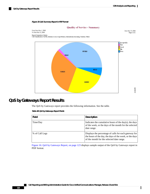
Page 135
Figure 16: QoS by Gateways Report
QoS by Call Types Report Results
The QoS by Call Types report provides the following information. See the table.
Table 50: QoS by Call Types Report Fields
Description
Field
The cumulative hours of the day(s), the days of the
week, or the days of the month for the selected date
range.
Time/Day
The percentage of calls for each gateway for the hours
of the day, the days of the week, or the days of the
month for the selected date range.
% of Call Legs
Call Reporting and Billing Administration Guide for Cisco Unified Communications Manager, Release 15 and SUs
123
CDR Analysis and Reporting
QoS by Call Types Report Results
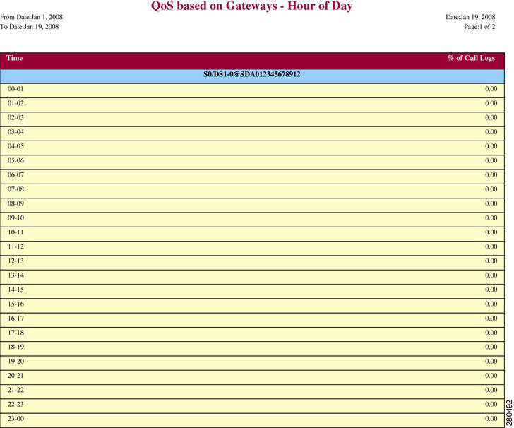
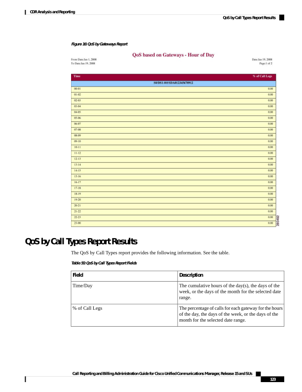
Page 136
Description
Field
Calls, including intracluster calls, that originate in the
Unified Communications Manager network and end
in the same Unified Communications
Managernetwork (no gateways or trunks are used).
Internal
Local calls that are routed through the public switched
telephone network (PSTN) to numbers without an
area code or that include one of the local area codes.
Local
Long-distance calls that originate in the Unified
Communications Manager network and go out through
the PSTN.
Long Distance
International calls that originate in the Unified
Communications Manager network that go out through
the PSTN.
International
Outgoing calls that originate on one Unified
Communications Manager network, go out through
a trunk, and terminate on a different Unified
Communications Manager network. For CAR
purposes, be aware that any outgoing call can be
classified as an OnNet call if it is configured as such
in the CAR dial plan configuration window. See Set
Up Dial Plan, on page 31.
On Net
Inbound calls that originate outside the Unified
Communications Manager network, enter through a
gateway, and go into the Unified Communications
Manager network.
Incoming
Inbound calls that originate outside the Unified
Communications Manager network, enter the Unified
Communications Manager network through a gateway,
and are transferred outbound from the Unified
Communications Manager network through a gateway.
Tandem
All other outgoing calls, such as toll-free numbers or
emergency calls such as 911.
Others
Figure 17: QoS by Call Types Report, on page 125 displays sample output of the QoS by Call Types report in
PDF format.
Call Reporting and Billing Administration Guide for Cisco Unified Communications Manager, Release 15 and SUs
124
CDR Analysis and Reporting
QoS by Call Types Report Results
Page 137
Figure 17: QoS by Call Types Report
Traffic Summary Report Results
The Traffic Summary and Traffic Summary by Phone Number reports contain the same information and
include some or all the following fields. See the table. A separate line displays under the report title for the
Busy Hour Call Completion (BHCC) number for that day.
Table 51: Traffic Summary Report Fields
Description
Field
The cumulative hours of the day(s), the days of the
week, or the days of the month for the selected date
range.
Time/Day
Call Reporting and Billing Administration Guide for Cisco Unified Communications Manager, Release 15 and SUs
125
CDR Analysis and Reporting
Traffic Summary Report Results
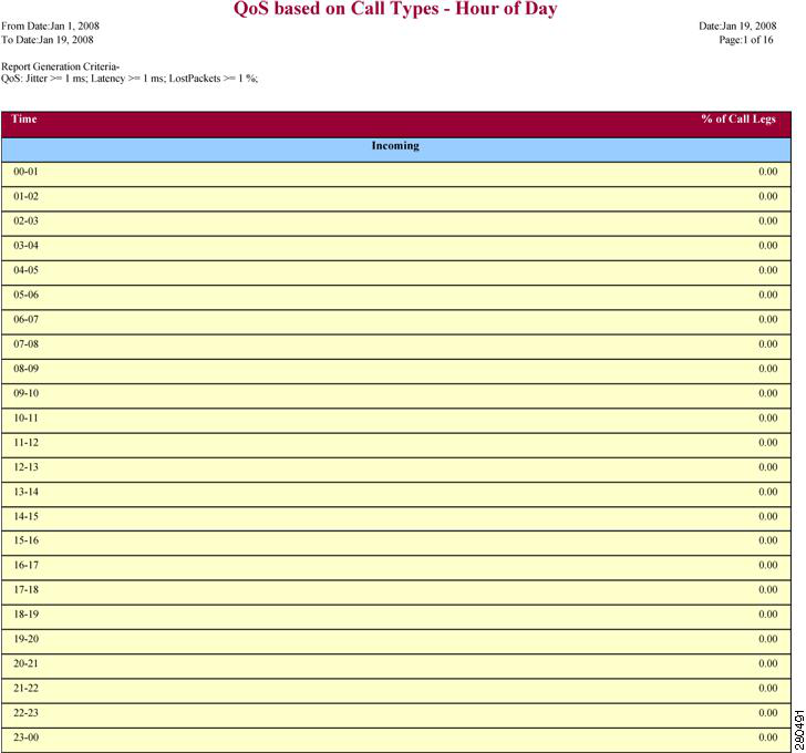
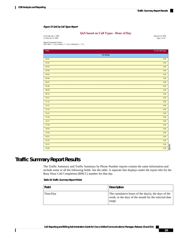
Page 138
Description
Field
The percentage of calls for each gateway for the hours
of the day, the days of the week, or the days of the
month for the selected date range.
Average Number of Calls
Outgoing calls that originate on one Unified
Communications Manager network, go out through
a trunk,and terminate on a different Unified
Communications Manager network. For CAR
purposes, be aware that any outgoing call can be
classified as an OnNet call if it is configured as such
in the CAR dial plan configuration window. See Set
Up Dial Plan, on page 31.
On Net
Calls, including intracluster calls, that originate in the
Unified Communications Manager network and end
in the same Unified Communications Manager
network (no gateways or trunks are used).
Internal
Local calls that are routed through the public switched
telephone network (PSTN) to numbers without an
area code or that include one of the local area codes.
Local
Long-distance calls that originate in the Unified
Communications Manager network and go out through
the PSTN.
Long Distance
International calls that originate in the Unified
Communications Manager network that goes out
through the PSTN.
International
Inbound calls that originate outside the Unified
Communications Manager network, enter through a
gateway and go into the Unified Communications
Manager network.
Incoming
Inbound calls that originate outside the Unified
Communications Manager network, enter the Unified
Communications Manager network through a gateway
and are transferred outbound from the Unified
Communications Manager network through a gateway.
Tandem
All other outgoing calls, such as toll-free numbers or
emergency calls such as 911.
Others
The total number of calls for each hour or day.
Total
Figure 18: Traffic Summary Report Results, on page 127 and Figure 19: Traffic Summary By Phone Number
Report Results, on page 128 display sample output of the Traffic Summary and the Traffic Summary by Phone
Number report results in PDF format.
Call Reporting and Billing Administration Guide for Cisco Unified Communications Manager, Release 15 and SUs
126
CDR Analysis and Reporting
Traffic Summary Report Results
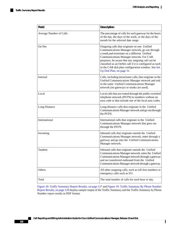
Page 139
Figure 18: Traffic Summary Report Results
Call Reporting and Billing Administration Guide for Cisco Unified Communications Manager, Release 15 and SUs
127
CDR Analysis and Reporting
Traffic Summary Report Results
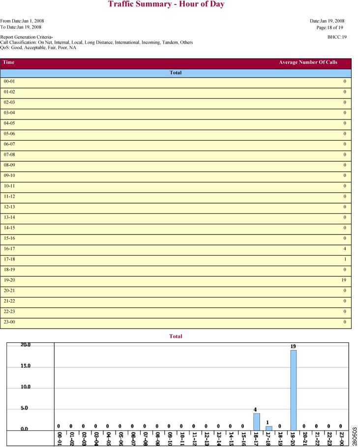
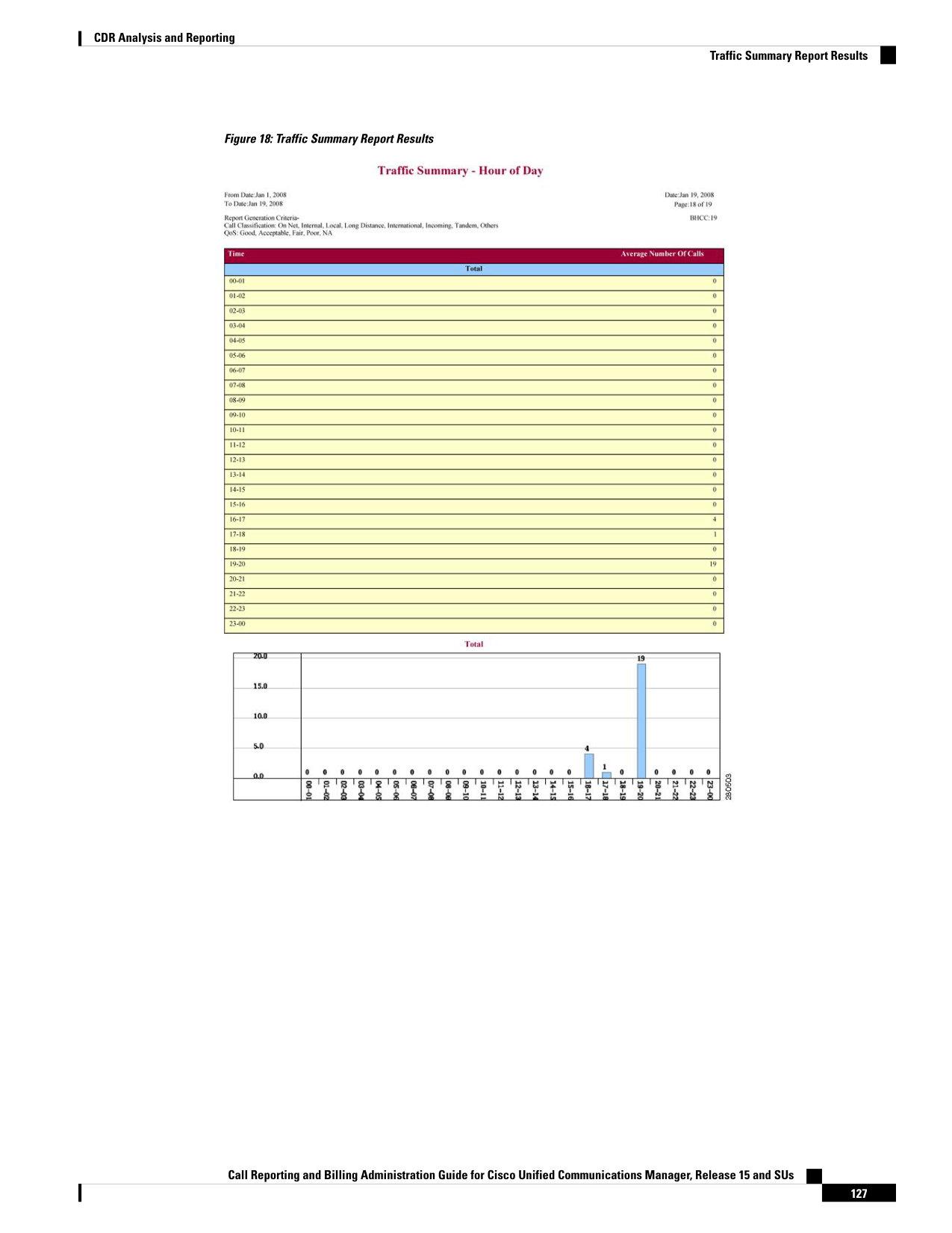
Page 140
Figure 19: Traffic Summary By Phone Number Report Results
Authorization Code Name Call Details Report Results
This report shows the usage of specific authorization code names. For security purposes, the authorization
code name (description) displays and not the authorization code. The Authorization Code Name Call Details
report includes the following fields (see the table).
Table 52: Authorization Code Name Call Details Report Fields
Description
Field
The originating number from which the call was
placed.
Orig.
The destination number to which the call was directed.
Dest.
The date and time that the call originated.
Orig. Date Time
The time, in seconds, that the call connected.
Duration (sec)
Call Reporting and Billing Administration Guide for Cisco Unified Communications Manager, Release 15 and SUs
128
CDR Analysis and Reporting
Authorization Code Name Call Details Report Results
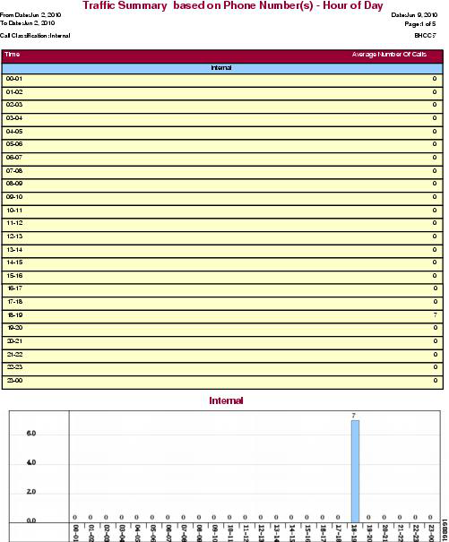
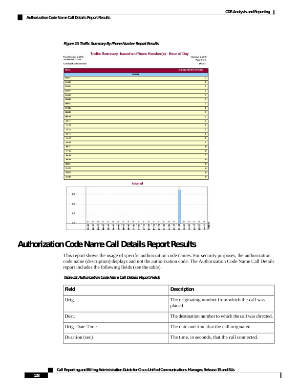
Page 141
Description
Field
The type of call (internal, incoming, on so on.)
Call Classification
The authorization level for calls for each chosen
authorization code name.
Authorization Level
Figure 20: Authorization Code Name Call Details Report, on page 129 displays sample output of the
Authorization Code Name Call Details report in PDF format.
Figure 20: Authorization Code Name Call Details Report
Authorization Level Call Details Report Results
This report shows the usage of specific authorization levels. The Authorization Level Call Details report
includes the following fields (see the table).
Table 53: Authorization Level Call Details Report Fields
Description
Field
The originating number from which the call was
placed.
Orig.
The destination number to which the call was directed.
Dest.
The date and time that the call originated.
Orig. Date Time
The time, in seconds, that the call connected.
Duration (sec)
The type of call (internal, incoming, and so on.)
Call Classification
The authorization code name for each authorization
level that you chose.
Authorization Code Name
Figure 21: Authorization Level Call Details Report, on page 130 displays sample output of the Authorization
Level Call Details report in PDF format.
Call Reporting and Billing Administration Guide for Cisco Unified Communications Manager, Release 15 and SUs
129
CDR Analysis and Reporting
Authorization Level Call Details Report Results
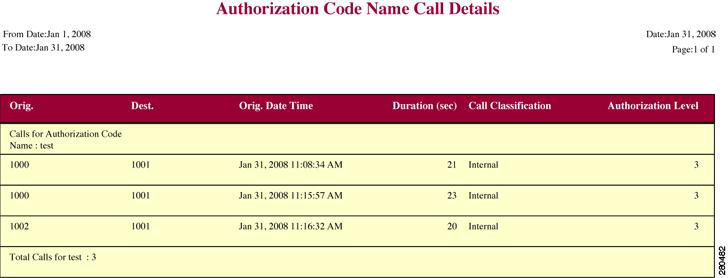
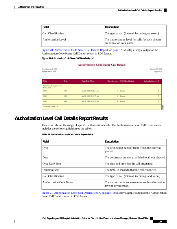
Page 142
Figure 21: Authorization Level Call Details Report
Client Matter Code Details Report Results
The report shows the usage of specific client matter codes. The Client Matter Code Details report includes
the following fields (see the following table).
Table 54: Detail Report Fields
Description
Field
The originating number from which the call was
placed.
Orig.
The destination number to which the call was directed.
Dest.
The date and time that the call originated.
Orig. Date Time
The time, in seconds, that the call connected.
Duration (sec)
The type of call (internal, incoming, and so on).
Call Classification
Figure 22: Client Matter Code Details Report, on page 131 displays sample output of the Client Matter Code
Details report in PDF format.
Call Reporting and Billing Administration Guide for Cisco Unified Communications Manager, Release 15 and SUs
130
CDR Analysis and Reporting
Client Matter Code Details Report Results
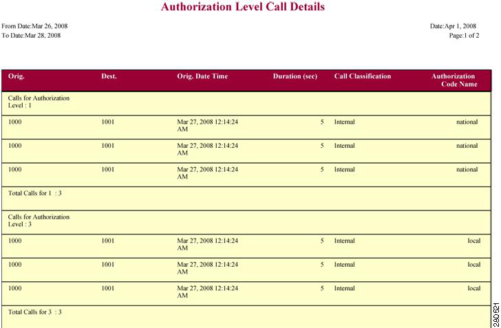
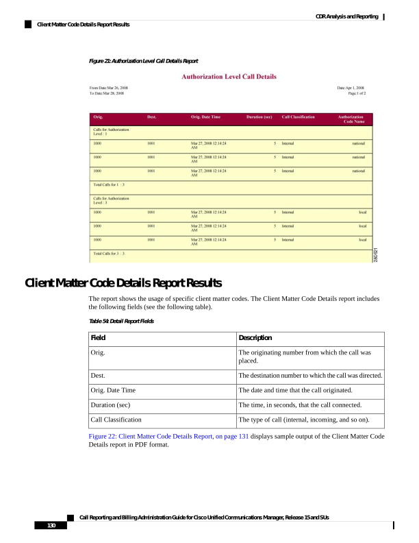
Page 143
Figure 22: Client Matter Code Details Report
Malicious Call Details Report Results
The Malicious Call Details report provides information about malicious calls. The report provides the following
fields. See the table.
Table 55: Malicious Call Details Report Fields
Description
Field
Time at which the malicious call originated.
Orig. Time
Time at which the malicious call terminated.
Term. Time
Total time of malicious call in seconds.
Duration
Originating DN.
Orig.
Destination DN.
Dest.
Name of the originating device.
Orig. Device
Name of the destination device.
Dest. Device
Classification of the malicious call.
Call Classification
Figure 23: Malicious Calls Detail Report, on page 132 displays sample output of the Malicious Calls Detail
report in PDF format.
Call Reporting and Billing Administration Guide for Cisco Unified Communications Manager, Release 15 and SUs
131
CDR Analysis and Reporting
Malicious Call Details Report Results
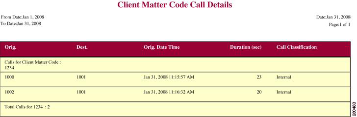
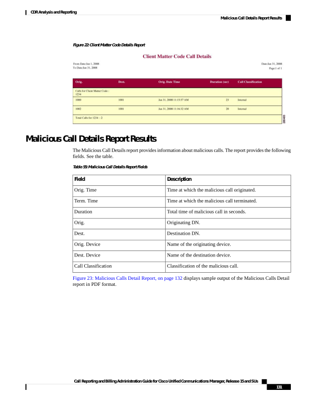
Page 144
Figure 23: Malicious Calls Detail Report
Precedence Call Summary Report Results
The Precedence Call Summary report provides information about calls based on precedence levels. The report
displays the call summary for the precedence values in the form of a bar chart on an “Hour of Day,” “Day of
Week,” or “Day of Month” basis for each precedence level that you choose. If you choose to display the report
in PDF format, two tables, one reflecting the bar chart, and the other listing the “Number of Calls” and
“Percentage” for each precedence level that was chosen, display in the report. See the table.
Table 56: Precedence Call Summary Report Fields
Description
Field
Indicates the cumulative hours of the day(s), the days
of the week, or the days of the month for the selected
date range.
Time/Day
Number of calls for each precedence level by
time/day.
Call Legs
Precedence level value of the call.
Precedence Level
Number of call legs per each precedence level.
No. of Call Legs
Percentage of calls per each precedence level.
Percentage
Figure 24: Precedence Call Summary Report, on page 133 displays sample output of the Precedence Call
Summary by Hour of Day report in PDF format.
Call Reporting and Billing Administration Guide for Cisco Unified Communications Manager, Release 15 and SUs
132
CDR Analysis and Reporting
Precedence Call Summary Report Results
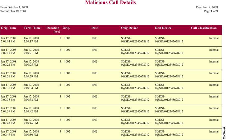
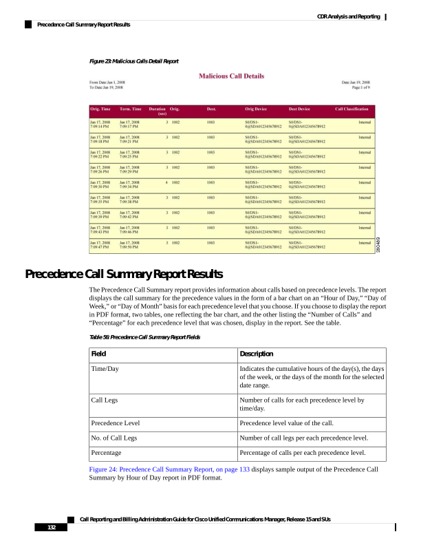
Page 145
Figure 24: Precedence Call Summary Report
System Report Results
The system overview provides information about all parts of the Unified Communications Manager network.
The report provides the following sections. See the table.
Call Reporting and Billing Administration Guide for Cisco Unified Communications Manager, Release 15 and SUs
133
CDR Analysis and Reporting
System Report Results
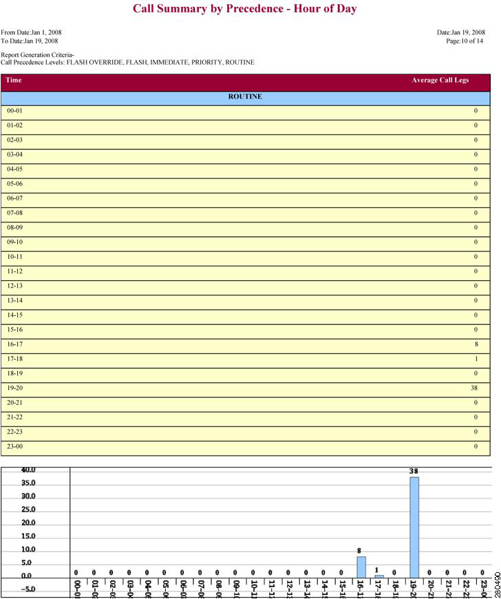
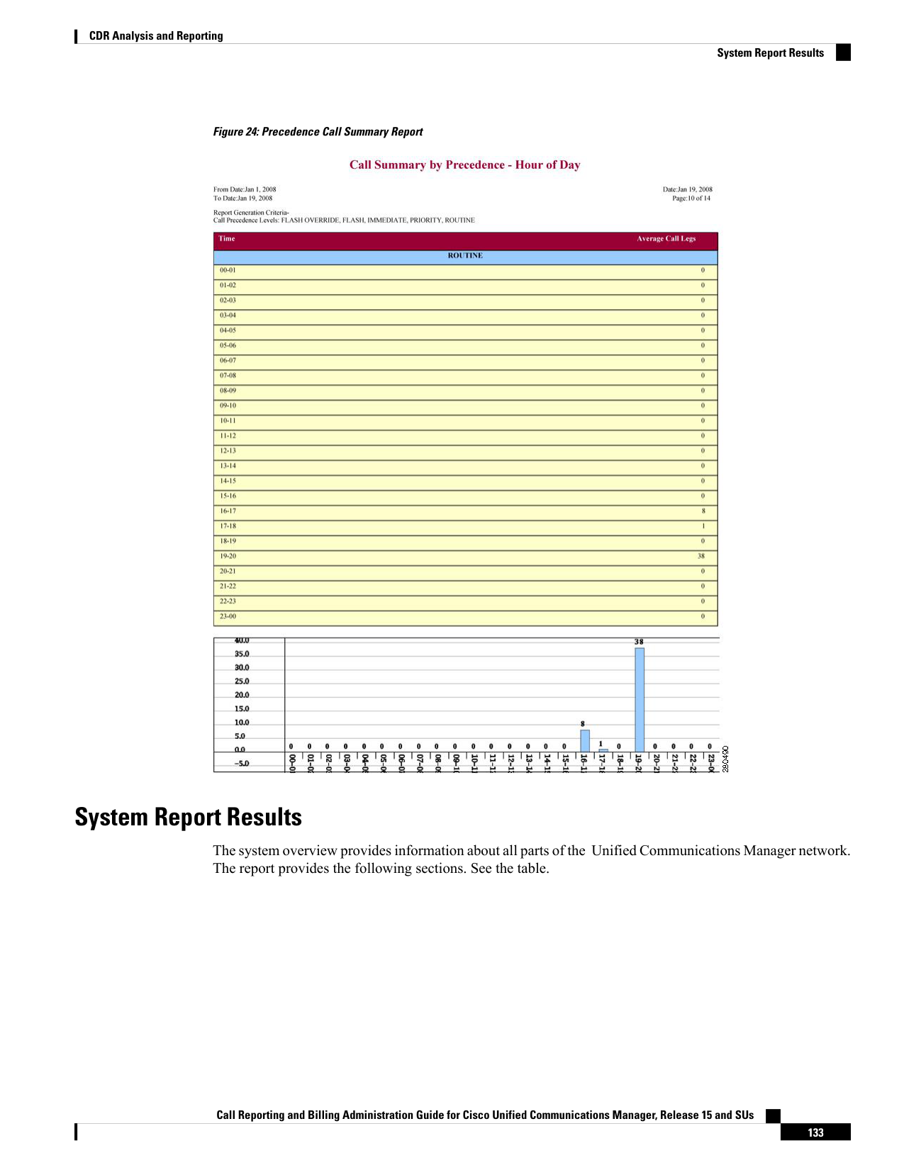
Page 146
Table 57: System Overview Report
Description
Field
Details the five users who have incurred the highest
charges for calls that occurred during the specified
date range. See the Top N by Charge or Duration
Report Results, on page 82 for details about this
section of the system overview report.
Top 5 Users based on Charge
Details the five called numbers that have incurred the
highest charges for calls during the specified date
range. See the Top N by Charge or Duration Report
Results, on page 82 for details about this section of
the system overview report.
Top 5 Destinations based on Charge
Details the five calls that have incurred the highest
charges for calls during the specified date range. See
the Top N by Charge or Duration Report Results, on
page 82 for details about this section of the system
overview report.
Top 5 Calls based on Charge
Details the five users who have spent the most time
on calls during the specified date range. See Top N
by Charge or Duration Report Results, on page 82
for details about this section of the system overview
report.
Top 5 Users based on Duration
Details the five called numbers that have been engaged
in calls for the longest time during the specified date
range. See the Top N by Charge or Duration Report
Results, on page 82 for details about this section of
the system overview report.
Top 5 Destinations based on Duration
Details the five longest calls for the specified date
range. See the Top N by Charge or Duration Report
Results, on page 82 for details about this section of
the system overview report.
Top 5 Calls based on Duration
Shows the volume of calls during the specified date
range based on each hour of the day. If the date range
is within one day, the system identifies the hour with
the highest traffic volume (the BHCC number). See
the Traffic Summary Report Results, on page 125 for
details about this section of the system overview
report.
Traffic Summary Report - Hour of Day
Shows the volume of calls during the specified date
range based on each day of the week. See the Traffic
Summary Report Results, on page 125 for details about
this section of the system overview report.
Traffic Summary Report - Day of Week
Call Reporting and Billing Administration Guide for Cisco Unified Communications Manager, Release 15 and SUs
134
CDR Analysis and Reporting
System Report Results
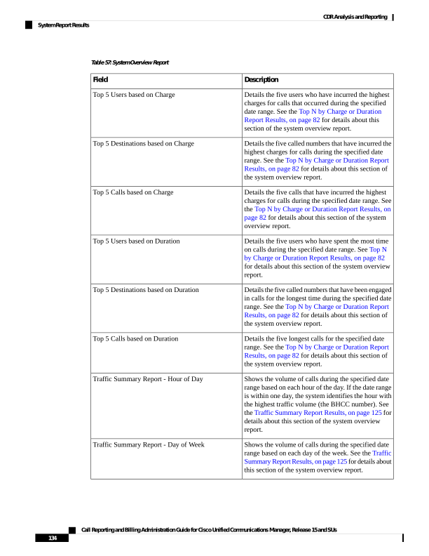
Page 147
Description
Field
Shows the volume of calls during the specified date
range based on each day of the month. See the Traffic
Summary Report Results, on page 125 for details about
this section of the system overview report.
Traffic Summary Report - Day of Month
Shows the number of calls that fell within each
voice-quality category during the specified date range.
See the QoS Summary Report Results, on page 121
for details about this section of the system overview
report.
Quality of Service Report - Summary
Shows the summary of the call classification for each
gateway along with the QoS, the number of calls, and
the duration for each classification for the gateway
during the specified date range. See the QoS by
Gateways Report Results, on page 122 for details about
this section of the system overview report.
Gateway Summary Report
CDR Error Report Results
The CDR Error report provides the following information. See the following table.
Table 58: CDR Error Report Fields
Description
Field
The hour of the specified day that the error occurred.
Time
The total number of CDR records that were not
processed during the CAR load because of an error.
No of Error CDRs
The total number of CDR records that were
successfully loaded into CAR.
No of Valid CDRs
The percentage of failed CDR data records out of all
the CDR data records to be loaded.
% of Error CDRs
The following figure displays sample output of the CDR Error report in PDF format.
Call Reporting and Billing Administration Guide for Cisco Unified Communications Manager, Release 15 and SUs
135
CDR Analysis and Reporting
CDR Error Report Results
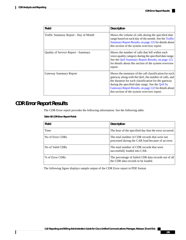
Page 148
Figure 25: CDR Error Report
Call Reporting and Billing Administration Guide for Cisco Unified Communications Manager, Release 15 and SUs
136
CDR Analysis and Reporting
CDR Error Report Results
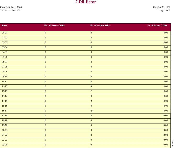
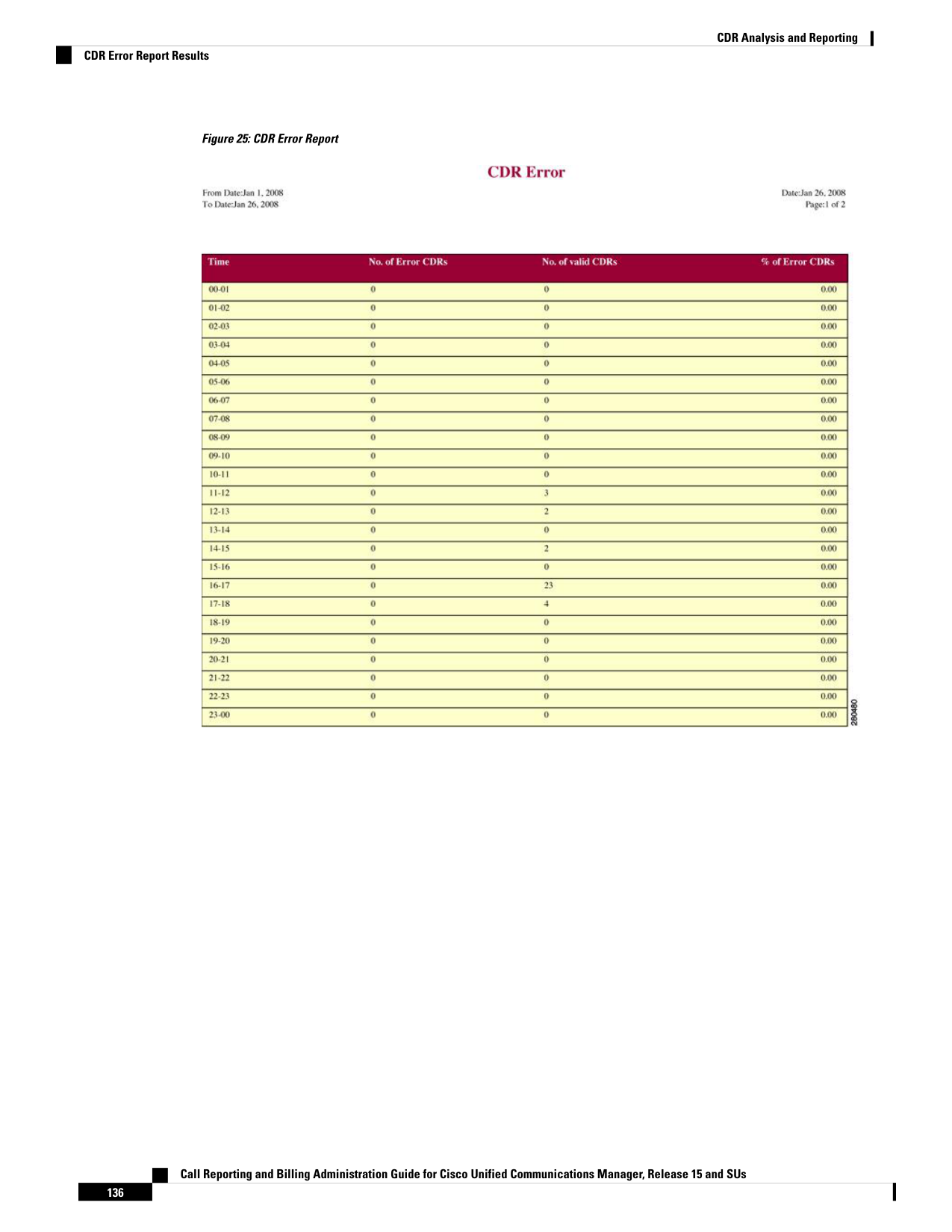
Page 149
C H A P T E R 6
Device Reports
• CAR Device Reports, on page 137
• Gateway Device Reports, on page 139
• Route Pattern and Hunt Pilot Device Reports, on page 145
• Conference Bridge Device Reports, on page 152
• Voice Messaging Utilization Device Reports, on page 154
• Trunk Device Reports, on page 157
• CAR Device Reports Results, on page 159
CAR Device Reports
CAR provides reporting capabilities for three levels of users: administrators, managers, and individual users.
Only administrators generate device reports.
Device reports track the load and performance of Unified Communications Manager related devices, such
as conference bridges, voice-messaging servers, gateways, and trunks.
Device Reports Summary Descriptions
Device reports help CAR administrators track the load and performance of Unified Communications
Manager-related devices, such as conference bridges, voice-messaging server, gateways, and trunks. This
section describes the device reports:
• Gateway
• Detail - Available for CAR administrators. Use the Gateway Detail report to track issues with specific
gateways. The report provides a list of calls that used the specified gateways. Use this report to
review detailed information about chosen gateways. You can specify gateways by type, such as all
or some of the VG200 gateways in your system, or by only those gateways that use a particular
route pattern. You can also specify search criteria based on call types and QoS values.
• Summary - Available for CAR administrators. The Gateway Summary report provides a summary
of all the calls that went through the gateways. It also provides the total number of calls and duration
for each of the categories, namely Incoming, Tandem, and Outgoing (Long Distance, Local,
International, Others, OnNet), and, also, the total calls for each QoS value for each gateway in the
system. Use this report to track the functionality of the system on a daily basis. If you discover
issues that need to be studied further, use the gateway detail report.
Call Reporting and Billing Administration Guide for Cisco Unified Communications Manager, Release 15 and SUs
137

Page 150
• Utilization - Available for CAR administrators. The Gateway Utilization report provides an estimate
of the utilization percentage of the gateway(s). You can examine the usage on the basis of each hour
of a day or by a specified number of days of the week or month. Reports generate for each gateway
that is chosen. Use this report for load balancing or capacity planning (to evaluate the need for
adding or removing gateways, depending on their utilization). You can specify gateways by type,
such as all or some of the VG200 gateways in your system, or by only those gateways that use a
particular route pattern.
• Route Patterns/Hunt Pilots
• Route and Line Group Utilization - Only CAR administrators can generate the Route and Line
Group Utilization report. This report provides an estimated utilization percentage of the chosen
route and line group(s). You can examine the usage on the basis of each hour of a day or by a
specified number of days of the week or month. Reports generate for each chosen route and line
group. Use the report to analyze whether the route and line group capacity is sufficient to meet the
usage requirements. Based on the results, you can decide whether additions are required. If you are
load balancing gateways by using different route and line groups or route patterns and hunt lists
that are assigned to the gateways, you can use this report to see the load for the whole grouping.
This report also provides a convenient way of generating utilization information for a grouping of
gateways by a particular route and line group; the group will also include any H.323 fallback
gateways that are using the specified route and line group.
• Route/Hunt List Utilization - Available for CAR administrators. The Route/Hunt List Utilization
report provides an estimated utilization percentage of the chosen route/hunt list(s). You can examine
the usage on the basis of each hour of a day or by a specified number of days of the week or month.
Reports generate for each chosen route/hunt list. Use the report to analyze whether the route and
line group capacity is sufficient to meet the usage requirements. Based on the results, you can decide
whether additions are required. If you are load balancing gateways by using different route/hunt
lists that are assigned to the gateways, you can use this report to see the load for the whole grouping.
This report also provides a convenient way of generating utilization information for a grouping of
gateways by a particular route/hunt list; the group will also include any H.323 fallback gateways
that are using the chosen route/hunt list.
• Route Pattern/Hunt Pilot Utilization - Available for CAR administrators. The Route Pattern/Hunt
Pilot Utilization report provides an estimated utilization percentage of the chosen route pattern(s)/hunt
pilot(s). You can examine the usage on the basis of each hour of a day or by a specified number of
days of the week or month. Reports generate for each chosen route pattern/hunt pilot. Use the report
to analyze system usage on the chosen route pattern/hunt pilot.
• Hunt Pilot Summary - Only CAR administrators generate the Hunt Pilot Summary Report.The CDR
Hunt Pilot Call Summary report displays the call details for the specified hunt pilot. This report
displays an only an overview of the calls for the hunt pilots and hunt member information is not
included. The CAR administrator can generate report for a maximum of five hunt pilot DNs.
• Hunt Pilot Detail - Only CAR administrators generate the Hunt Pilot Detailed Call Report. This
report displays call details for a hunt pilot number or a hunt member dn.
• Conference Call Details - Available for CAR administrators. The Conference Call Details report allows
you to generate and view details about conference calls and conference bridges. The Summary Report
displays the summary information of conference calls within a chosen date/time range but does not
contain information about each individual conference participant call leg. The Detailed Report displays
the detailed information about the conference calls within a chosen date/time range and includes
information about each individual conference participant call leg.
Call Reporting and Billing Administration Guide for Cisco Unified Communications Manager, Release 15 and SUs
138
CDR Analysis and Reporting
Device Reports Summary Descriptions
Page 151
• Conference Bridge Utilization - Available for CAR administrators. The Conference Bridge Utilization
report provides an estimate of the utilization percentage of the conference bridge(s). You can examine
the usage on the basis of each hour of a day or by a specified number of days of the week or month.
Generate reports for all the conference bridges in the system. Use this report to determine the activity
on the conference bridge(s) and whether you need to add additional resources. This report helps you
identify usage patterns, so you can plan capacity when you discover recurring peaks in the usage pattern.
• Voice Messaging Utilization - Available for CAR administrators. The Voice Messaging Utilization report
provides an estimate of the utilization percentage of the voice-messaging device(s). You can examine
the usage on the basis of each hour of a day or by a specified number of days of the week or month.
Reports generate for each voice-messaging device. Use this report to determine the activity on the voice
messaging device(s) and whether you need to add additional resources. This report helps you to identify
usage patterns, so you can plan capacity when you discover recurring peaks in the usage pattern.
• Trunk Utilization - Available for CAR administrators. Only CAR administrators generate the Trunk
Utilization report. This report calculates the utilization reports for devices based on the duration of calls
that passed through the devices. You can generate this report on an hourly, daily, or monthly basis.
Reports generate for each trunk that is chosen. You can use this report for capacity assessment. You can
also generate utilization reports for route groups, route lists and route patterns that are connected through
trunks.
Gateway Device Reports
CAR provides reporting capabilities for three levels of users: administrators, managers, and individual users.
Only administrators generate device reports.
Device reports track the load and performance of Unified Communications Manager related devices, such
as conference bridges, voice-messaging servers, and gateways.
Only CAR administrators generate the gateway reports. The following sections describe how to configure
Gateway Detail, Gateway Summary, and Gateway Utilization reports.
Generate Gateway Detail Reports
Only CAR administrators generate the Gateway Detail report. Use the Gateway Detail report to track issues
with specific gateways.
This section describes how to generate, view, or mail detailed information about selected gateways.
Procedure
Step 1
Choose Device Reports > Gateway > Detail.
The Gateway Detail window appears.
Step 2
To display the list of gateways that you can include in the report, in the List of Gateways box perform one of
the following tasks:
a)
To display all gateways in the List of Gateways box, click Gateway Types in the column on the left side
of the window.
Call Reporting and Billing Administration Guide for Cisco Unified Communications Manager, Release 15 and SUs
139
CDR Analysis and Reporting
Gateway Device Reports
Page 152
b) To display gateways for a particular gateway type in the List of Gateways box, click the icon next to
Gateway Types in the column on the left side of the window. The tree structure expands, and a list of
gateway types displays. Choose a gateway type from the list, and the gateway name displays in the List
of Gateways box.
Note
The List of Gateways box lists up to 200 gateways that are configured for the chosen gateway type.
c)
To display all gateways that are associated with configured route patterns/hunt pilots, click the
Route/Patterns/Hunt Pilots in the column on the left side of the window.
d) To display gateways that use a particular route pattern, rather than a gateway type, click the icon next to
Route Patterns/Hunt Pilots in the column on the left side of the window. The tree structure expands and
displays a list of route patterns/hunt lists. Choose a route pattern/hunt pilot from the list, and the gateway
name displays in the List of Gateways box.
Note
You can also search for specific route patterns/hunt lists by entering part of the name of the route
pattern(s)/hunt list(s) in the Route Patterns/Hunt Pilots box in the column on the left side of the window.
CAR searches for the route pattern(s)/hunt list(s) that matches the search string.
Step 3
In the List of Gateways box, choose the gateways that you want to include in the report.
Note
You can generate a report for up to five gateways at a time.
Step 4
To move the chosen gateway to the list of Selected Gateways box, click the down arrow.
The gateway or gateways that you chose appear in the Selected Gateways box.
Step 5
In the Select Call Types area, check the check boxes for the types of calls that you want to include in the
report. The following table describes the call types.
Table 59: Gateway Details by Call Types
Description
Call Type
Outgoing calls that originate on one Unified
Communications Manager network, go out through
a trunk and terminate on a different Unified
Communications Manager network. For CAR
purposes, be aware that any outgoing call can be
classified as an OnNet call if it is configured as such
in the CAR dial plan configuration window. See Set
Up Dial Plan, on page 31.
On Net
Local calls that are routed through the public switched
telephone network (PSTN) to numbers without an
area code or that include one of the local area codes.
Local
Long-distance calls that originate in the Unified
Communications Manager network and go out through
the PSTN.
Long Distance
Call Reporting and Billing Administration Guide for Cisco Unified Communications Manager, Release 15 and SUs
140
CDR Analysis and Reporting
Generate Gateway Detail Reports
Page 153
Description
Call Type
International calls that originate in the Unified
Communications Manager network and go out through
the PSTN.
International
Inbound calls that originate outside the Unified
Communications Manager network, enter through a
gateway and go into the Unified Communications
Manager network.
Incoming
Inbound calls that originate outside the Unified
Communications Manager network, enter the Unified
Communications Manager network through a gateway
and transfer outbound from the Unified
Communications Manager network through a gateway.
Tandem
All other outgoing calls, such as toll-free numbers or
emergency calls such as 911.
Others
Step 6
In the Select QoS area, check the check boxes for the voice-quality categories that you want to include in the
report. The parameters that are set in the following table provide the basis for all voice-quality categories.
Table 60: Gateway Detail Voice Quality
Description
Voice Quality
QoS for these calls represents the highest possible
quality.
Good
QoS for these calls, although slightly degraded, still
falls within an acceptable range.
Acceptable
QoS for these calls represents degraded quality but
still within a usable range.
Fair
QoS for these calls represents unsatisfactory quality.
Poor
These calls do not match any criteria for the
established QoS categories.
NA
Step 7
Choose the date range for the period for which you want to see call information.
Note
Ensure the date and time range does not exceed one month.
Step 8
Choose CSV in the Report Format area, if you want the report in CSV format. Choose PDF in the Report
Format area, if you want the report in PDF format.
Step 9
Click View Report.
Step 10
Click Send Report, if you want to mail the report. To send the report, follow the procedure that is described
in the Mail Reports, on page 63.
Call Reporting and Billing Administration Guide for Cisco Unified Communications Manager, Release 15 and SUs
141
CDR Analysis and Reporting
Generate Gateway Detail Reports
Page 154
Generate Gateway Summary Reports
Only CAR administrators generate the Gateway Summary report. This report provides a summary of all the
calls that went through the gateways. You can use this information for monitoring the traffic and QoS for
calls through the gateways.
You can either view reports that the system automatically generates or generate new reports. Only CAR
administrators can schedule reports for automatic generation. For more information, see CAR System
Parameters, on page 30.
This section describes how to generate, view, or mail summary information about gateways.
Procedure
Step 1
Choose Device Reports > Gateway > Summary.
The Gateway Summary window displays.
Step 2
In the Available Reports field, choose an automatically generated report (if available) and go to Step 6, on
page 143 or use the default setting, Generate New Report and go to Step 3, on page 142.
Step 3
In the Select Call Types area, check the check boxes for the types of calls that you want to include in the
report. The following table describes the call types.
Tip
To check all check boxes, click Select All; to uncheck the check boxes, click Clear All.
Table 61: Gateway Summary by Call Types
Description
Call Type
Outgoing calls that originate on one Unified
Communications Manager network, go out through
a trunk and terminate on a different Unified
Communications Manager network. For CAR
purposes, be aware that any outgoing call can be
classified as an OnNet call if it is configured as such
in the CAR dial plan configuration window. See Set
Up Dial Plan, on page 31.
On Net
Calls, including intracluster calls, that originate in the
Unified Communications Manager network and end
in the same Unified Communications Manager
network (no gateways or trunks are used).
Internal
Local calls that are routed through the public switched
telephone network (PSTN) to numbers without an
area code or that include one of the local area codes.
Local
Long-distance calls that originate in the Unified
Communications Manager network and go out through
the PSTN.
Long Distance
Call Reporting and Billing Administration Guide for Cisco Unified Communications Manager, Release 15 and SUs
142
CDR Analysis and Reporting
Generate Gateway Summary Reports
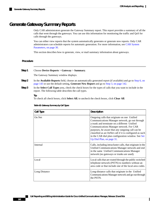
Page 155
Description
Call Type
International calls that originate in the Unified
Communications Manager network and go out through
the PSTN.
International
Inbound calls that originate outside the Unified
Communications Manager network, enter through a
gateway and go into the Unified Communications
Manager network.
Incoming
Inbound calls that originate outside the Unified
Communications Manager network, enter the Unified
Communications Manager network through a gateway
and transfer outbound from the Unified
Communications Manager network through a gateway.
Tandem
All other outgoing calls, such as toll-free numbers or
emergency calls such as 911.
Others
Step 4
If you chose Generate New Report, choose the date range of the period for which you want to generate the
report.
Step 5
Choose CSV in the Report Format area, if you want the report in CSV format. Choose PDF in the Report
Format area, if you want the report in PDF format.
Step 6
Click View Report.
Step 7
Click Send Report, if you want to mail the report. To send the report, perform the procedure that is described
in the Mail Reports, on page 63.
Generate Gateway Utilization Reports
Only CAR administrators generate the Gateway Utilization report. The report provides an estimate of the
utilization percentage of the gateway for the period and not the exact utilization. For example, the system
calculates the utilization of a gateway between 11hrs-12hrs, as the (sum of the duration of the calls that used
the gateway in that hour / (maximum duration seconds in an hour * maximum number of ports in a gateway
- number of days between the fromDate and toDate selected) * 100). Similarly, to get a utilization for the
whole day, the system calculates the utilization as mentioned for each hour. You can examine the usage based
on each hour of a day or on a specified number of days for each week or month.
In the case of weekly utilization reports, the system calculates the utilization as ((sum of the duration of the
calls that used the gateway in a day) / (maximum duration seconds in each day * number of each day between
the fromDate and toDate selected * maximum number of ports in a gateway) * 100).
In the case of monthly utilization reports, the system calculates the utilization as ((sum of the duration of the
calls that used the gateway in a day) / (maximum duration seconds in each day * number of each day between
the fromDate and toDate selected * maximum number of ports in a gateway) * 100).
Reports generate for each gateway that is chosen.
For calculation of the utilization of H.323 gateways, the system uses the port numbers from the CAR Gateway
Configuration window. To find this window, choose System > System Parameters > Gateway Configuration.
You cannot take port details for H.323 gateways from the Unified Communications Manager database because
Call Reporting and Billing Administration Guide for Cisco Unified Communications Manager, Release 15 and SUs
143
CDR Analysis and Reporting
Generate Gateway Utilization Reports
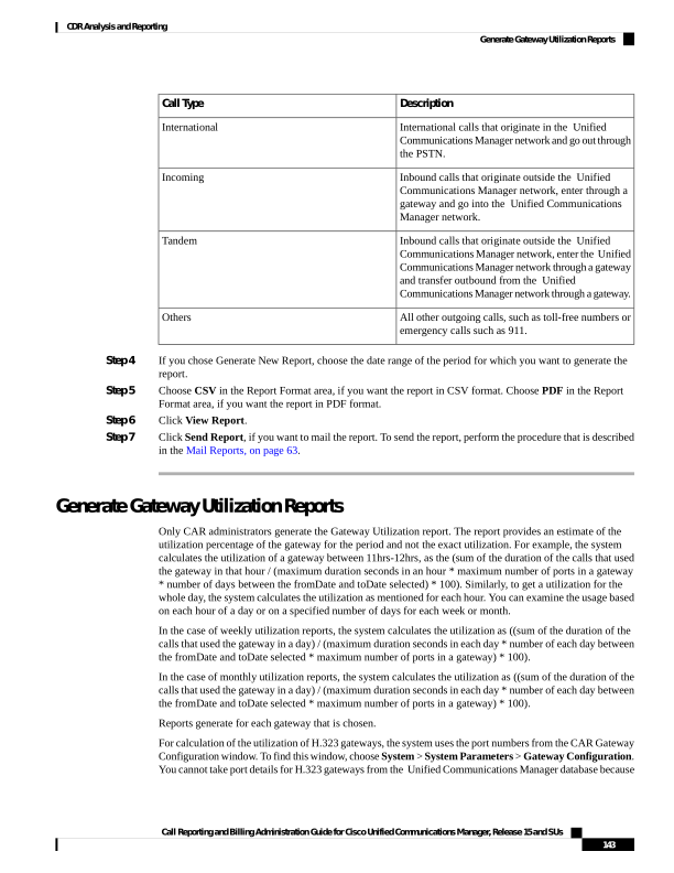
Page 156
the H.323 port number always equals zero in the database. The user must update H.323 gateway ports
information in the CAR Gateway Configuration window.
Be aware that the only port detail information that is taken from the CAR Gateway Configuration window is
only for those gateways that do not have port details that are available or that show zero in the Unified
Communications Manager database.
You can either view reports that the system automatically generates or generate new reports. Only CAR
administrators can schedule reports for automatic generation. For more information, see CAR System
Parameters, on page 30.
This section describes how to generate, view, or mail Gateway Utilization reports.
Procedure
Step 1
Choose Device Reports > Gateway > Utilization.
The Gateway Utilization window displays.
Step 2
In the Generate Reports field, choose a time as described in the following table.
Table 62: Generate Report Fields
Description
Parameter
Displays the cumulative utilization for each hour in
a 24-hour period for the period that you specify in
Step 8, on page 145.
Hour of Day
Displays the cumulative utilization for the days of the
week that occur within the period that you specify in
Step 8, on page 145.
Day of Week
Displays the cumulative utilization for the days of the
month that occur within the period that you specify
in Step 8, on page 145.
Day of Month
Step 3
In the Available Reports field, choose an automatically generated report (if available) and go to Step 10, on
page 145 or use the default Generate New Report and go to Step 4, on page 144.
Step 4
To display the list of gateways that you can include in the report in the List of Gateways box, perform one of
the following tasks:
a)
To display all gateways in the List of Gateways box, click Gateway Types in the column on the left side
of the window.
b) To display gateways for a particular gateway type in the List of Gateways box, click the icon next to
Gateway Types in the column on the left side of the window. The tree structure expands, and a list of
gateway types displays. Choose a gateway type from the list, and the gateway name displays in the List
of Gateways box.
Note
The List of Gateways box will list up to 200 gateways that are configured for the chosen gateway type.
Call Reporting and Billing Administration Guide for Cisco Unified Communications Manager, Release 15 and SUs
144
CDR Analysis and Reporting
Generate Gateway Utilization Reports
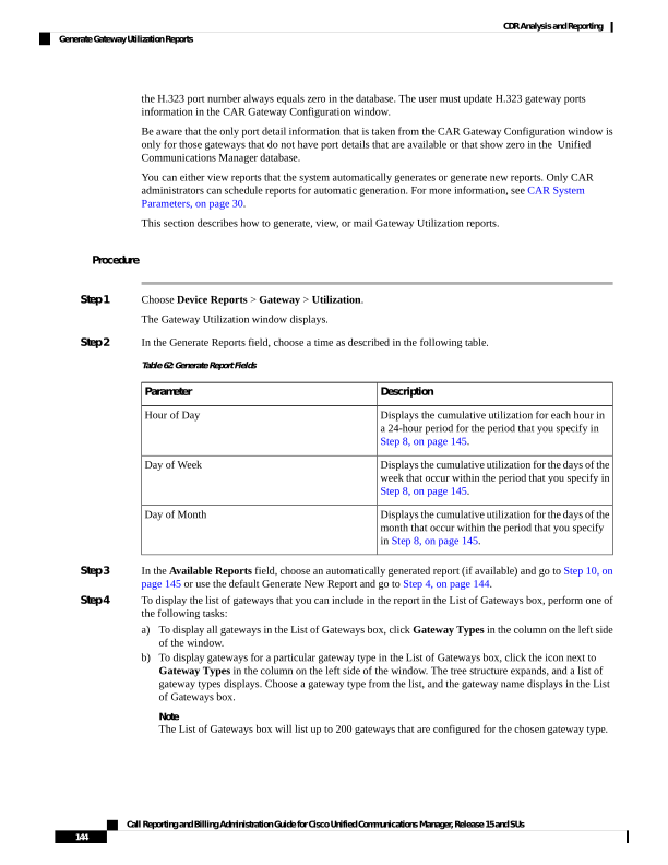
Page 157
c)
To display all gateways that are associated with configured route patterns/hunt pilots, click Route
Patterns/Hunt Pilots in the column on the left side of the window.
d) To display gateways that use a particular route pattern, rather than a gateway type, click the icon next to
Route Patterns/Hunt Pilots in the column on the left side of the window. The tree structure expands and
displays a list of route patterns/hunt lists. Choose a route pattern/hunt pilot from the list, and the gateway
name displays in the List of Gateways box.
Note
You can also search for specific route patterns/hunt lists by entering part of the name of the route
pattern(s)/hunt list(s) in the Route Patterns/Hunt Pilots box in the column on the left side of the window.
CAR searches for the route pattern(s)/hunt list(s) that matches the search string.
Step 5
Choose a gateway type from the list.
The gateway name displays in the List of Gateways box.
Note
The List of Gateways box will display up to 200 gateways that are configured for the chosen gateway type.
Step 6
In the List of Gateways box, choose the gateways that you want to include in the report.
Note
You can generate a report for up to five gateways at a time.
Step 7
To move the chosen gateway to the list of Selected Gateways box, click the down arrow.
The gateway(s) that you chose displays in the Selected Gateways box.
Step 8
If you chose Generate New Report, enter the date range of the period for which you want to see call
information.
Note
Ensure the date and time range does not exceed one month.
Step 9
If you want the report in CSV format, choose CSV in the Report Format area. If you want the report in PDF
format, choose PDF in the Report Format area.
Step 10
Click View Report.
Step 11
Click Send Report, if you want to mail the report. To send the report, perform the procedure that is described
in the Mail Reports, on page 63.
Route Pattern and Hunt Pilot Device Reports
CAR provides reporting capabilities for three levels of users: administrators, managers, and individual users.
Only administrators generate the Route Pattern and Hunt Pilot device reports.
Device reports track the load and performance of Unified Communications Manager related devices, such
as conference bridges, voice-messaging servers, and gateways.
Call Reporting and Billing Administration Guide for Cisco Unified Communications Manager, Release 15 and SUs
145
CDR Analysis and Reporting
Route Pattern and Hunt Pilot Device Reports
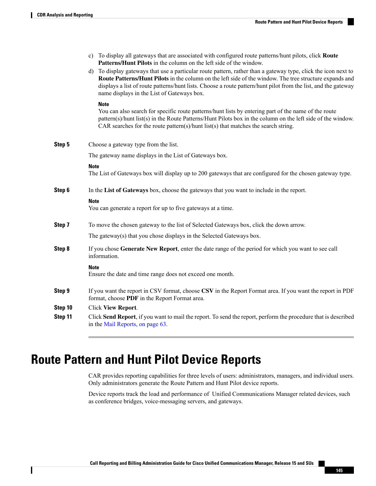
Page 158
Generate Route and Line Group Utilization Reports
Only CAR administrators generate the Route and Line Group Utilization report. This report provides an
estimate of the maximum utilization percentage of the route and line group (cumulative utilization of all the
gateways under the route and line group) for the period and not the exact utilization. The system calculates
the utilization in the same manner as is done for Gateway Utilization, but this calculation gives cumulative
utilization of all the gateways under the route groups and all the lines under the line groups. You can examine
the usage based on each hour of a day or on a specified number of days for each week or month. Reports
generate for each of the selected route and line groups.
You can either view reports that the system automatically generates or generate new reports. Only CAR
administrators can schedule reports for automatic generation. For more information, see CAR System
Parameters, on page 30.
This section describes how to generate, view, or mail Route and Line Group Utilization reports.
Procedure
Step 1
Choose Device Reports > Route Patterns/Hunt Pilots > Route and Line Group Utilization.
The Route and Line Group Utilization window displays.
Step 2
In the Generate Reports field, choose a time as described in the following table.
Table 63: Generate Report Fields
Description
Parameter
Displays the cumulative utilization for each hour in
a 24-hour period for the period that you specify in
Step 8, on page 147.
Hour of Day
Displays the cumulative utilization for the days of the
week that occur within the period that you specify in
Step 8, on page 147.
Day of Week
Displays the cumulative utilization for the days of the
month that occur within the period that you specify
in Step 8, on page 147.
Day of Month
Step 3
In the Available Reports field, choose an automatically generated report (if available) and go to Step 10, on
page 147, or use the default setting, Generate New Report, and go to Step 4, on page 146.
Step 4
To choose only those route and line groups that use a particular route pattern, click Route Patterns/Hunt
Pilots in the column on the left side of the window.
The tree structure expands and displays the route patterns/hunt lists that you chose.
Note
You can also search for specific route patterns/hunt lists by entering part of the name of the route pattern(s)/hunt
list(s) in the Route Patterns/Hunt Pilots box in the column on the left side of the window. CAR searches for
the route pattern(s)/hunt list(s) that matches the search string.
Call Reporting and Billing Administration Guide for Cisco Unified Communications Manager, Release 15 and SUs
146
CDR Analysis and Reporting
Generate Route and Line Group Utilization Reports
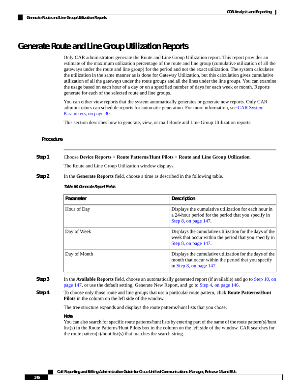
Page 159
Step 5
Choose a route pattern/hunt list from the list.
The route and line groups for this route pattern/hunt list display in the List of Route/Line Groups box.
Note
The List of Route/Line Groups box will display up to 200 route groups.
Step 6
In the List of Route/Line Groups box, choose the route/line groups that you want to include in the report.
Note
You can generate a report for up to five route/line groups at a time.
Step 7
To move the chosen gateway to the list of Selected Route/Line Groups box, click the down arrow.
The route/line groups that you chose to display in the Selected Route Groups box.
Step 8
If you chose Generate New Report, enter the date range of the period for which you want to see call information.
Note
Ensure the date and time range does not exceed one month.
Step 9
If you want the report in CSV format, choose CSV in the Report Format area. If you want the report in PDF
format, choose PDF in the Report Format area.
Step 10
Click View Report.
Step 11
Click Send Report, if you want to mail the report. To send the report, follow the procedure that is described
in the Mail Reports, on page 63.
Generate Route and Hunt List Utilization Reports
Only CAR administrators generate the Route/Hunt List Utilization report. The Route/Hunt List Utilization
report provides an estimate of the maximum utilization percentage of the route/hunt list (cumulative utilization
of all the gateways under the route/hunt list) for the period and not the exact utilization. The system calculates
the cumulative utilization of all the gateways under the route lists and all the lines under the hunt lists.
You can examine the usage based on each hour of a day or on a specified number of days for each week or
month. Reports generate for each of the selected route/hunt lists.
You can either view reports that the system automatically generates or generate new reports. Only CAR
administrators can schedule reports for automatic generation. For more information, see Set Up CDR Load
Schedule, on page 36.
This section describes how to generate, view, or mail the Route/Hunt List Utilization reports.
Procedure
Step 1
Choose Device Reports > Route Patterns/Hunt Pilots > Route/Hunt List Utilization.
The Route/Hunt List Utilization window displays.
Step 2
In the Generate Report field, choose a time as described in the following table.
Call Reporting and Billing Administration Guide for Cisco Unified Communications Manager, Release 15 and SUs
147
CDR Analysis and Reporting
Generate Route and Hunt List Utilization Reports
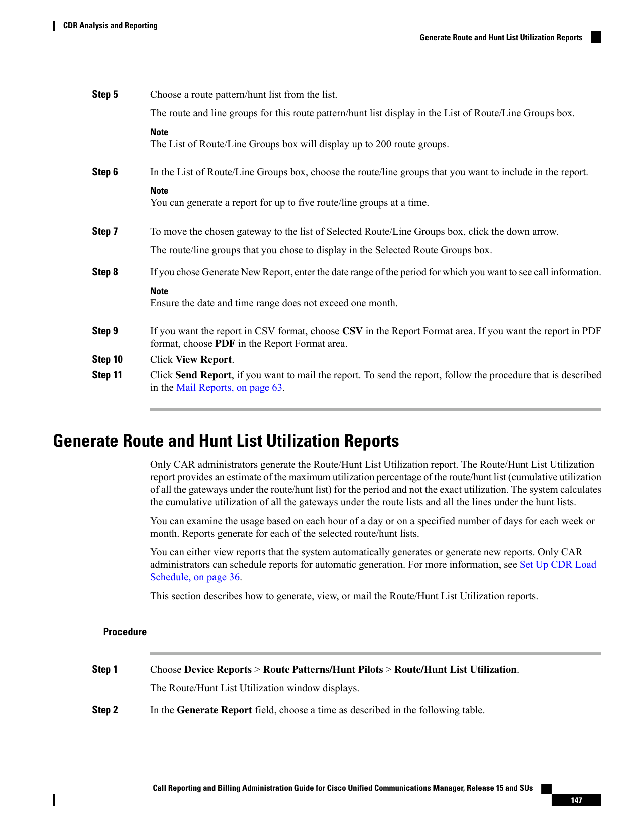
Page 160
Table 64: Generate Report Fields
Description
Parameter
Displays the cumulative utilization for each hour in
a 24-hour period for the period that you specify in
Step 8, on page 148.
Hour of Day
Displays the cumulative utilization for the days of the
week that occur within the period that you specify in
Step 8, on page 148.
Day of Week
Displays the cumulative utilization for the days of the
month that occur within the period that you specify
in Step 8, on page 148.
Day of Month
Step 3
In the Available Reports field, choose an automatically generated report (if available) and go to Step 10, on
page 148 or use the default setting, Generate New Report, and go to Step 4, on page 148.
Step 4
To choose the route/hunt lists that you want to include in the report, click Route Patterns/Hunt Pilots in the
column on the left side of the window. The tree structure expands and displays the route patterns/hunt pilots
that you chose.
Note
You can also search for specific route patterns/hunt lists by entering part of the name of the route pattern(s)/hunt
lists in the Route Patterns/Hunt Pilots box in the column on the left side of the window. CAR searches for the
route pattern(s)/hunt list(s) that matches the search string.
Step 5
Choose a route/hunt list from the list.
The route/hunt list name displays in the List of Route/Hunt Lists box.
Note
The List of Route/Hunt Lists box will display up to 200 route/hunt lists.
Step 6
In the List of Route/Hunt Lists box, choose the route/hunt lists that you want to include in the report.
Note
You can generate a report for up to five route/hunt lists at a time.
Step 7
To move the chosen route/hunt lists to the list of Selected Route/Hunt Lists box, click down arrow.
The route/hunt lists that you chose to display in the Selected Route/Hunt Lists box.
Step 8
If you chose Generate New Report, enter the date range of the period for which you want to see call information.
Note
Ensure the date and time range does not exceed one month.
Step 9
If you want the report in CSV format, choose CSV in the Report Format area. If you want the report in PDF
format, choose PDF in the Report Format area.
Step 10
Click View Report.
Call Reporting and Billing Administration Guide for Cisco Unified Communications Manager, Release 15 and SUs
148
CDR Analysis and Reporting
Generate Route and Hunt List Utilization Reports
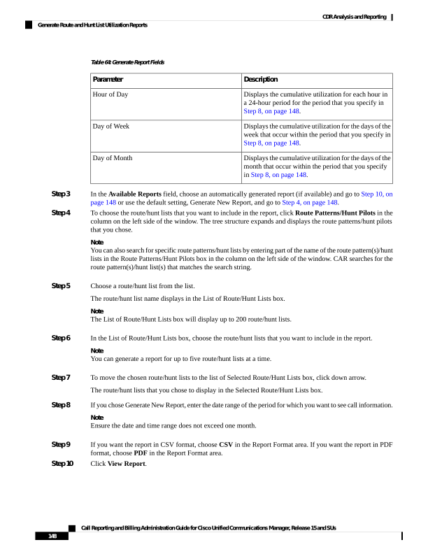
Page 161
Step 11
Click Send Report, if you want to mail the report. To send the report, perform the procedure that is described
in the Mail Reports, on page 63.
Generate Route Pattern and Hunt Pilot Utilization Reports
Only CAR administrators generate the Route Pattern/Hunt Pilot Utilization report. The report provides an
estimate of the maximum utilization percentage of the route pattern/hunt pilot (cumulative utilization of all
the gateways under the route pattern/hunt pilot) for the period and not the exact utilization. The system
calculates the utilization of all the gateways under the route patterns and all the lines under the hunt pilots.
You can examine the usage based on each hour of a day or on a specified number of days for each week or
month. Reports generate for each of the selected route patterns/hunt pilots.
You can either view reports that the system automatically generates or generate new reports. Only CAR
administrators can schedule reports for automatic generation. For more information, see Set Up CDR Load
Schedule, on page 36.
This section describes how to generate, view, or mail Route Pattern/Hunt Pilot Utilization reports.
Procedure
Step 1
Choose Device Reports > Route Pattern/Hunt Pilots > Route Pattern/Hunt Pilot Utilization.
The Route Pattern/Hunt Pilot Utilization window displays.
Step 2
In the Generate Report field, choose a time as described in the following table.
Table 65: Generate Report Fields
Description
Parameter
Displays the cumulative utilization for each hour in
a 24-hour period for the period that you specify in
Step 8, on page 150.
Hour of Day
Displays the cumulative utilization for the days of the
week that occur within the period that you specify in
Step 8, on page 150.
Day of Week
Displays the cumulative utilization for the days of the
month that occur within the period that you specify
in Step 8, on page 150.
Day of Month
Step 3
In the Available Reports field, choose an automatically generated report (if available) and go to Step 10, on
page 150 or use the default Generate New Report and go to Step 4, on page 149.
Step 4
To choose the route pattern(s)/hunt list(s) that you want to include in the report, click Route Patterns/Hunt
Pilots in the column on the left side of the window.
The tree structure expands and displays the route pattern(s)/hunt list(s) that you chose.
Note
Call Reporting and Billing Administration Guide for Cisco Unified Communications Manager, Release 15 and SUs
149
CDR Analysis and Reporting
Generate Route Pattern and Hunt Pilot Utilization Reports
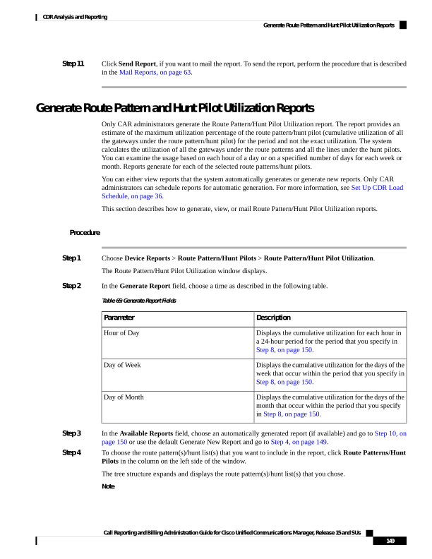
Page 162
You can also search for specific route patterns/hunt lists by entering part of the name of the route pattern(s)/hunt
list(s) in the Route Patterns box in the column on the left side of the window. CAR searches for the route
pattern(s)/hunt list(s) that matches the search string.
Step 5
Choose a route pattern/hunt pilot from the list.
The route pattern/hunt pilot name displays in the List of Route Patterns/Hunt Pilots box.
Note
The List of Route Patterns/Hunt Pilots box will display up to 200 route patterns/hunt lists.
Step 6
In the List of Route Patterns/Hunt Pilots box, choose the route patterns/hunt lists that you want to include in
the report.
Note
You can generate a report for up to five route patterns/hunt pilots at a time.
Step 7
Click the down arrow to move the chosen route pattern/hunt pilot to the list of Selected Route Patterns/Hunt
Pilots box.
The route pattern/hunt pilot that you chose displays in the Selected Route Patterns/Hunt Pilots box.
Step 8
If you chose Generate New Report, enter the date range of the period for which you want to see call information.
Note
Ensure the date and time range does not exceed one month.
Step 9
If you want the report in CSV format, choose CSV in the Report Format area. If you want the report in PDF
format, choose PDF in the Report Format area.
Step 10
Click View Report.
Step 11
Click Send Report, if you want to mail the report. To send the report, perform the procedure that is described
in the Mail Reports, on page 63.
Generate Hunt Pilot Summary Report
Only CAR administrators generate the Hunt Pilot Summary Report. The CDR Hunt Pilot Call Summary report
displays the call details for the specified hunt pilot. This report displays only an overview of the calls for the
hunt pilots and hunt member information is not included. The CAR administrator can a generate report for a
maximum of five hunt pilot DNs.
This section describes how to generate, view, or mail Hunt Pilot Summary reports.
Procedure
Step 1
Choose Device Reports > Route Pattern/Hunt Pilots > Hunt Pilot Summary.
The Hunt Pilot Detail Summary displays.
Step 2
Enter the hunt pilot number in the Hunt Pilots text box and press the Enter key.
Call Reporting and Billing Administration Guide for Cisco Unified Communications Manager, Release 15 and SUs
150
CDR Analysis and Reporting
Generate Hunt Pilot Summary Report
Page 163
The hunt pilot number is displayed below the text box. Alternately, you can click the icon to display all the
available hunt pilot numbers.
Step 3
Click on the required hunt pilot number, so that it is listed in the List of Hunt Pilots.
Step 4
From the Generate Reports drop-down list, choose:
a)
Hour of the day - Displays the call details for each hour in a 24-hour period for the period that you specify
in Step 7, on page 151.
b) Day of the Week - Displays the call details for the days of the week that occur within the period that you
specify in Step 7, on page 151.
c)
Day of the Month - Displays the call details for the days of the month that occur within the period that
you specify in Step 7, on page 151.
Step 5
Choose any of the available reports or the Generate New Report option from the Available Reports drop-down
list.
Step 6
From the list of hunt pilots available, choose the required ones and click the down arrow.
The hunt pilots chosen are displayed in the Selected Hunt Pilots list.
Step 7
Choose the From Date and the To Date from the drop-down lists available.
Step 8
Choose the required report format.
It can either be CSV or PDF. PDF is the default report option.
Step 9
Click View Report to view the report.
To view the report results, see Generate Hunt Pilot Summary Report, on page 150.
Step 10
Click Send Report, if you want to mail the report.
To send the report, perform the procedure that is described in the Mail Reports, on page 63.
Generate Hunt Pilot Detail Report
Only CAR administrators generate the Hunt Pilot Detailed Call Report. This report displays call details for a
hunt pilot number or a hunt member dn.
This section describes how to generate, view, or mail Hunt Pilot Detail reports.
Procedure
Step 1
Choose Device Reports > Route Pattern/Hunt Pilots > Hunt Pilot Detail.
The Hunt Pilot Detail window displays.
Step 2
Select the HuntPilot or the MemberDn for generating the report.
Step 3
Enter the hunt pilot number in the Hunt Pilots text box and press the Enter key.
The hunt pilot number is displayed below the text box. Alternately, you can click the icon to display the hunt
pilot numbers.
Call Reporting and Billing Administration Guide for Cisco Unified Communications Manager, Release 15 and SUs
151
CDR Analysis and Reporting
Generate Hunt Pilot Detail Report
Page 164
Step 4
If you had selected the hunt pilot option, click on the required hunt pilot number, so that it is listed in the
SelectedHuntPilot/MemberDn list box. Proceed to Step 7, on page 152.
Step 5
If you had selected the member dn option, click on the required hunt pilot number to list the member dn
numbers in it.
Step 6
From the list of member dns, click on the required ones so that they get listed in the
SelectedHuntPilot/MemberDn list box.
Step 7
Choose any of the available reports or the Generate New Report option from the Available Reports drop-down
list.
Step 8
Choose the From Date and the To Date from the drop-down lists available.
Step 9
Choose the required report format.
It can either be CSV or PDF. PDF is the default report option.
Step 10
Click View Report to view the report.
To view the report results, see Hunt Pilot Detail Report Results, on page 168.
Step 11
Click Send Report, if you want to mail the report.
To send the report, perform the procedure that is described in the Mail Reports, on page 63.
Conference Bridge Device Reports
CAR provides reporting capabilities for three levels of users: administrators, managers, and individual users.
Only CAR administrators generate the conference bridge device reports.
Device reports track the load and performance of Unified Communications Manager related devices, such
as conference bridges, voice-messaging servers, and gateways.
Generate Conference Call Details
Only CAR administrators generate the Conference Call Details report. The Conference Call Details report
allows you to generate and view details about conference calls.
This section describes how to generate, view, or mail a Conference Call Details report.
Procedure
Step 1
Choose Device Reports > Conference Bridge > Call Details.
The Conference Call Details window displays.
Step 2
In the Report Type drop-down menu, choose either Summary or Detail.
Step 3
In the Available Reports field, choose an automatically generated report (if available) and go to Step 7, on
page 153 or use the default setting, Generate New Report, and go to Step 4, on page 152.
Step 4
In Select Conference Types, check the check box of the conference type that you want to include in the report
as described in the following table.
Call Reporting and Billing Administration Guide for Cisco Unified Communications Manager, Release 15 and SUs
152
CDR Analysis and Reporting
Conference Bridge Device Reports
Page 165
Table 66: Conference Calls Detail Fields
Description
Parameter
Ad hoc conferences allow the conference controller
to let only certain participants into the conference.
Ad-Hoc
Meet-me conferences allow users to dial in to a
conference.
Meet-Me
Step 5
If you chose Generate New Report, enter the date range of the period for which you want to see conference
call details.
Note
Ensure that the date and time range does not exceed one month.
Step 6
Choose CSV in the Report Format area, if you want the report in CSV format. Choose PDF in the Report
Format area, if you want the report in PDF format.
Step 7
Click View Report.
Step 8
Click Send Report, if you want to mail the report. To send the report, perform the procedure that is described
in the Mail Reports, on page 63.
Generate Conference Bridge Utilization Reports
Only CAR administrators generate the Conference Bridge Utilization report. The report provides an estimate
of the utilization percentage of the conference bridges (cumulative utilization of all the conference bridges
that are selected for OnDemand reports) for the period and not the exact utilization. For example, the system
calculates the utilization of a conference bridge between 11hrs and 12hrs as the ((Sum of duration of the calls
that used the conference bridge in that hour) / (Number of days between the fromDate and toDate selected *
Maximum number of streams in the conference bridge * Maximum number of duration in seconds in an hour)
- 100)). The value that is calculated will display in the report as the utilization for the time between 11hrs and
12hrs. You can examine the usage based on each hour of a day or on a specified number of days for each
week or month.
You can either view reports that the system automatically generates or generate new reports. Only CAR
administrators can schedule reports for automatic generation. For more information, see Set Up CDR Load
Schedule, on page 36.
This section describes how to generate, view, or mail Conference Bridge Utilization reports for each conference
bridge type.
Procedure
Step 1
Choose Device Reports > Conference Bridge > Utilization.
The Conference Bridge Utilization window displays.
Step 2
In the Generate Report field, choose a time as described in the following table.
Call Reporting and Billing Administration Guide for Cisco Unified Communications Manager, Release 15 and SUs
153
CDR Analysis and Reporting
Generate Conference Bridge Utilization Reports
Page 166
Table 67: Generate Report Fields
Description
Parameter
Displays the cumulative utilization for each hour in
a 24-hour period for the period that you specify in
Step 6, on page 154.
Hour of Day
Displays the cumulative utilization for the days of the
week that occur within the period that you specify in
Step 6, on page 154.
Day of Week
Displays the cumulative utilization for the days of the
month that occur within the period that you specify
in Step 6, on page 154.
Day of Month
Step 3
In the Available Reports field, choose an automatically generated report (if available) and go to Step 8, on
page 154 or use the default, Generate New Report, and go to Step 4, on page 154.
Step 4
From the Conference Bridge Types column in the left pane, choose the conference bridge type(s) that you
want to include in the utilization report.
The conference bridges of the particular conference bridge type that you chose to display in the List of Devices
box.
Note
For this report, choose a maximum of five conference bridges.
Step 5
When you have chosen all the conference bridges that you want to include in the report, click the down arrow
to add them to the Selected Devices box.
Step 6
If you chose Generate New Report, enter the date range of the period for which you want to see call information.
Note
Ensure the date and time range does not exceed one month.
Step 7
If you want the report in CSV format, choose CSV in the Report Format area. If you want the report in PDF
format, choose PDF in the Report Format area.
Step 8
Click View Report.
Step 9
Click Send Report, if you want to mail the report. To send the report, perform the procedure described in the
Mail Reports, on page 63.
Voice Messaging Utilization Device Reports
CAR provides reporting capabilities for three levels of users: administrators, managers, and individual users.
Only administrators generate device reports.
Device reports track the load and performance of Unified Communications Manager related devices, such
as conference bridges, voice-messaging servers, and gateways.
Call Reporting and Billing Administration Guide for Cisco Unified Communications Manager, Release 15 and SUs
154
CDR Analysis and Reporting
Voice Messaging Utilization Device Reports
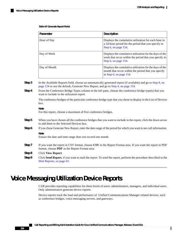
Page 167
Generate Voice Messaging Utilization Reports
Only CAR administrators generate the Voice Messaging Utilization report. The report provides an estimate
of the maximum utilization percentage of the voice-messaging devices for the period and not the exact
utilization. For example, the system calculates the utilization of a voice-messaging port/voice-messaging DNs
between 11hrs and 12hrs by using the duration of the calls that used the voice-messaging port/voice messaging
DNs. The system calculates utilization for the voice-messaging port as the (sum of duration of calls that used
the voice-messaging port in that hour*100) / (maximum duration seconds in an hour * number of days between
the fromDate and toDate selected). The utilization calculation for voice-messaging DNs represents the (sum
of duration of calls that used the voice-messaging DNs in that hour * 100) / (maximum duration seconds in
an hour * number of days between the fromDate and toDate selected * maximum number of ports in a gateway
that is connected to the voice-messaging DN). The same value will display in the report as the utilization for
the time between 11hrs and 12hrs.
You can review the Voice Messaging Utilization report for Voice Messaging Ports only as a newly generated
report and not as a report that the system automatically generates.
You can automatically generate the Voice Messaging Utilization report for Voice Messaging DNs, or you
can generate it as a new report. Only CAR administrators can schedule reports for automatic generation. For
more information, see Set Up CDR Load Schedule, on page 36.
The CAR Voice Messaging Utilization report supports the Cisco Unity and Cisco Unity Connection
voice-messaging systems.
Note
This section describes how to generate, mail, or view Voice Messaging Utilization reports.
Procedure
Step 1
Choose Device Reports > Voice Messaging > Utilization.
The Voice Messaging Utilization window displays.
Step 2
In the Generate Report field, choose a time as described in the following table.
Table 68: Generate Report Fields
Description
Parameter
Displays the utilization results for each hour in a
24-hour period for the period that you specify in
Step 10, on page 156.
Hour of Day
Displays the utilization for the days of the week that
occur within the period that you specify in Step 10,
on page 156.
Day of Week
Displays the utilization for the days of the month that
occur within the period that you specify in Step 10,
on page 156.
Day of Month
Call Reporting and Billing Administration Guide for Cisco Unified Communications Manager, Release 15 and SUs
155
CDR Analysis and Reporting
Generate Voice Messaging Utilization Reports

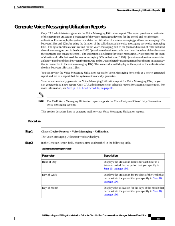
Page 168
Step 3
In the Available Reports field, choose an automatically generated report (if available) and go to Step 12, on
page 156 or use the default setting, Generate New Report, and go to Step 4, on page 156.
Step 4
To choose a voice-messaging DN, click Voice Messaging DNs in the Voice Utilization pane.
The previously configured voice-messaging DN displays.
Note
The Voice Messaging DN that displays in this window represents the Voice Messaging DN that you configure
in the VoiceMailDn service parameter, which supports the Cisco Messaging Interface service. Set the parameter
name VoiceMailDn to the routing pattern that you have created on the machine. Configure this by opening
Cisco Unified CM Administrationand clicking System. Click Service Parameters; then, select the service
Cisco Messaging Interface.
Step 5
Choose the voice-messaging DN.
The DN that you chose displays in the List of DNs/Ports list box.
Step 6
To choose a voice-messaging port, click Voice Messaging Ports in the Voice Utilization pane.
A list of configured voice-messaging ports displays.
Step 7
From the list of ports, choose a voice-messaging port.
The port that you chose displays in the List of DNs/Ports list box.
Step 8
In Select Voice Messaging DNs/Ports, click the down arrow.
The port that you chose displays in the Selected DNs/Ports list box.
Step 9
Repeat Step 7, on page 156 and Step 8, on page 156 until you have chosen the ports that you want to include
in the report.
Note
For this report, you can choose a maximum of five Voice Messaging Ports/Voice Messaging DNs. You can
choose the default Voice Messaging DN and four Voice Messaging Ports, or you can choose five Voice
Messaging Ports.
Step 10
If you chose Generate New Report, enter the date range of the period for which you want to see call
information.
Note
Ensure the date and time range does not exceed one month.
Step 11
Choose CSV in the Report Format area, if you want the report in CSV format. If you want the report in PDF
format, choose PDF in the Report Format area.
Step 12
Click View Report.
Step 13
Click Send Report, if you want to mail the report. To send the report, perform the procedure described in the
Mail Reports, on page 63.
Call Reporting and Billing Administration Guide for Cisco Unified Communications Manager, Release 15 and SUs
156
CDR Analysis and Reporting
Generate Voice Messaging Utilization Reports
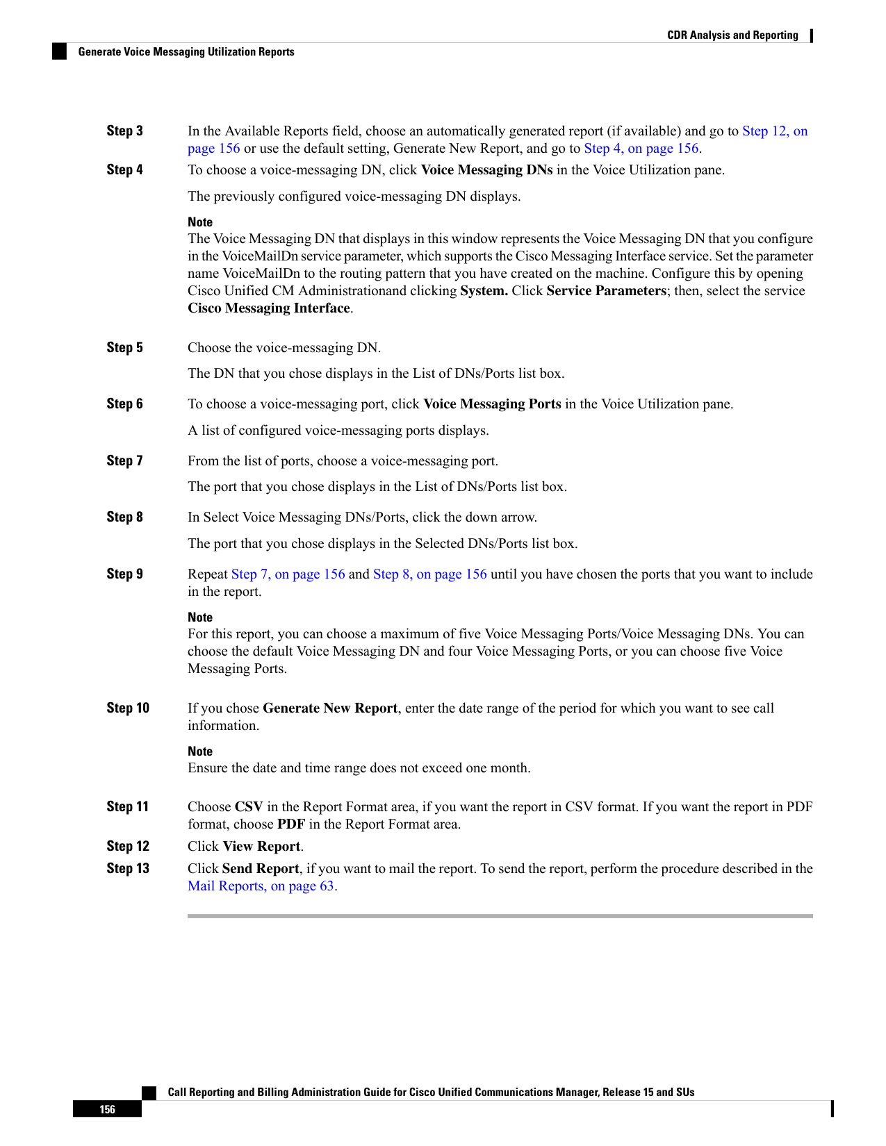
Page 169
Trunk Device Reports
CAR provides reporting capabilities for three levels of users: administrators, managers, and individual users.
Only administrators generate device reports.
Device reports track the load and performance of Unified Communications Manager related devices, such
as conference bridges, voice-messaging servers, gateways, and trunks.
Only CAR administrators generate the trunk reports. The following section describes how to configure Trunk
Utilization reports.
Generate Trunk Utilization Reports
Only CAR administrators generate the Trunk Utilization report. This report calculates the utilization reports
for devices based on the duration of calls that passed through the devices.
You can generate this report on an hourly, daily, or monthly basis. The system calculates the utilization of a
trunk for each hour in the selected date range. For example, the system calculates the utilization of a trunk
between 11hrs-12hrs, using the formula, (Sum of the duration of calls that used the trunk in that hour / (total
seconds in an hour * maximum number of ports in a trunk * number of days between the fromDate and toDate
selected) * 100).
Similarly, to get the utilization for each day in a week, the system calculates the utilization using the formula,
((sum of the duration of calls that used the trunk in a day) / (total seconds in each day * number of each day
between the fromDate and toDate selected * maximum number of ports in a trunk) * 100).
In the case of monthly utilization reports, the system calculates the utilization for each day in a month, using
the formula, ((sum of the duration of calls that used the trunk in a day) / (total seconds in each day * number
of each day between the fromDate and toDate selected * maximum number of ports in a trunk) * 100).
Reports generate for each trunk that is chosen.
For calculation of the trunk utilization, the system uses the port numbers from the CAR Trunk Configuration
window. To find this window, choose System > System Parameters > Trunk Configuration. You cannot
take port details for H.323 trunks from the Unified Communications Manager database because the H.323
port number always equals zero in the database. The user must update H.323 trunk ports information in the
CAR Trunk Configuration window.
Be aware that the only port detail information that is taken from the CAR Trunk Configuration window is
only for those trunks that do not have port details that are available or that show zero in the Unified
Communications Manager database.
This section describes how to generate, view, or mail Trunk Utilization reports.
Procedure
Step 1
Choose Device Reports > Trunk > Utilization.
The Trunk Utilization window displays.
Step 2
In the Generate Reports field, choose a time as described in the following table.
Call Reporting and Billing Administration Guide for Cisco Unified Communications Manager, Release 15 and SUs
157
CDR Analysis and Reporting
Trunk Device Reports
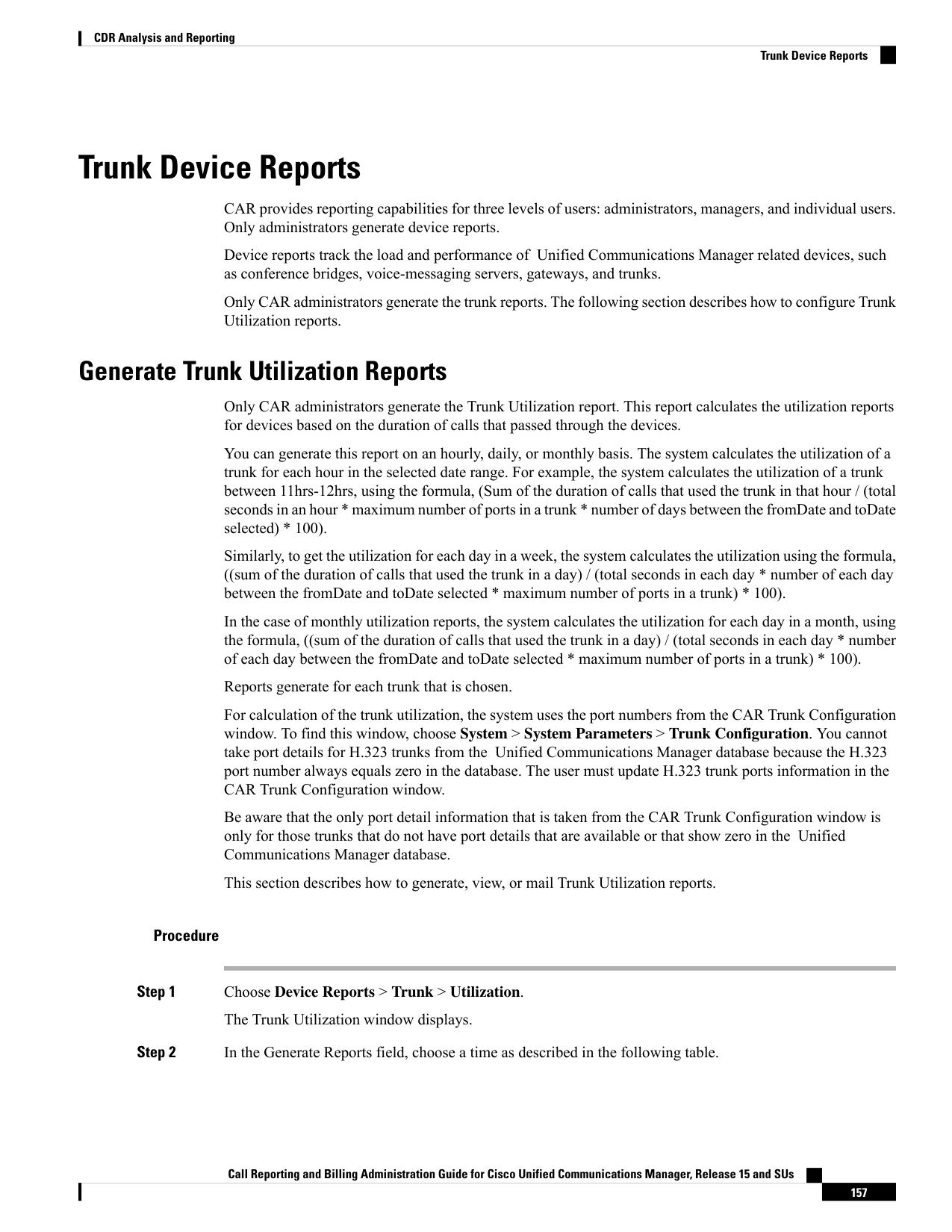
Page 170
Table 69: Generate Report Fields
Description
Parameter
Displays the cumulative utilization for each hour in
a 24-hour period for the period that you specify in
Step 7, on page 158.
Hour of Day
Displays the cumulative utilization for the days of the
week that occur within the period that you specify in
Step 7, on page 158.
Day of Week
Displays the cumulative utilization for the days of the
month that occur within the period that you specify
in Step 7, on page 158.
Day of Month
Note
The Trunk Utilization report is not generated automatically.
Step 3
To display the list of trunks that you can include in the report in the List of Trunks box, perform one of the
following tasks:
a)
To display all trunks in the List of Trunks box, click Trunk Types in the column on the left side of the
window.
b) To display trunks for a particular trunk type in the List of Trunks box, click the icon next to Trunk Types
in the column on the left side of the window. The tree structure expands, and a list of trunk types displays.
Choose a trunk type from the list, and the trunk name displays in the List of Trunks box.
Note
The List of Trunks box will list up to 200 trunks that are configured for the chosen trunk type.
Note
You can generate the trunk utilization reports for route groups, route lists, and route patterns that are
connected through trunks.
Step 4
Choose a trunk type from the list.
The trunk name displays in the List of Trunks box.
Note
The List of Trunks box displays up to 200 trunks that are configured for the chosen trunk type.
Step 5
In the List of Trunks box, choose the trunks that you want to include in the report.
Note
You can generate a report for up to five trunks at a time.
Step 6
To move the chosen trunk to the list of Selected Trunks box, click the down arrow.
The trunk(s) that you chose displays in the Selected Trunks box.
Step 7
If you chose Generate New Report, enter the date range of the period for which you want to see call information.
Note
Ensure the date and time range does not exceed one month.
Call Reporting and Billing Administration Guide for Cisco Unified Communications Manager, Release 15 and SUs
158
CDR Analysis and Reporting
Generate Trunk Utilization Reports
Page 171
Step 8
If you want the report in CSV format, choose CSV in the Report Format area. If you want the report in PDF
format, choose PDF in the Report Format area.
Step 9
Click View Report.
Step 10
Click Send Report, if you want to mail the report. To send the report, perform the procedure that is described
in the Mail Reports, on page 63.
CAR Device Reports Results
This chapter describes report output information for each device report.
Gateway Detail Report Results
The Gateway Detail report includes the following fields. See the table.
Table 70: Gateway Detail Report Fields
Description
Field
The date when the call went through the gateway.
Date
The time when the call went through the gateway.
Orig. Time
The time that the call terminated.
Term. Time
The duration, in seconds, that the call was connected.
The duration specifies the difference between the Dest
Connect and the Dest Disconnect times.
Duration(s)
The directory number from which the call was placed.
Orig
The directory number to which the call was originally
placed. If the call was not forwarded, this directory
number should match the Final Destination number.
If the call was forwarded, this field contains the
original destination number of the call before it was
forwarded.
Dest
The codec code (compression or payload code) that
the call originator used on its sending side during this
call. This code may differ from the codec code that
was used on its receiving side.
Orig. Codec
The codec code (compression or payload code) that
the destination used on its sending side during this
call. This code may differ from the codec code that
was used on its receiving side.
Dest. Codec
Call Reporting and Billing Administration Guide for Cisco Unified Communications Manager, Release 15 and SUs
159
CDR Analysis and Reporting
CAR Device Reports Results
Page 172
Description
Field
The device name of the device that placed the call.
For incoming and tandem calls, this field specifies
the device name of the gateway.
Orig. Device
The device name of the device that received the call.
For outgoing and tandem calls, this field specifies the
device name of a gateway. For conference calls, this
field specifies the device name of the conference
bridge.
Dest Device
QoS depicts the voice-quality grade that was achieved
for the calls.
Orig QoS
The QoS category that was experienced by the
receiver of the call.
Dest QoS
Figure 26: Gateway Detail Report, on page 160 displays sample output of the Gateway Detail Report in PDF
format.
Figure 26: Gateway Detail Report
Gateway Summary Report Results
The Gateway Summary report includes the following fields. See the following table.
The Gateway Summary report segregates calls for each call classification that the user selects and divides the
calls based on QoS type.
Note
Table 71: Gateway Summary Report Fields
Description
Field
Shows the type of call (internal, incoming, and
tandem.)
Call Classification
Call Reporting and Billing Administration Guide for Cisco Unified Communications Manager, Release 15 and SUs
160
CDR Analysis and Reporting
Gateway Summary Report Results

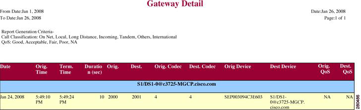
Page 173
Description
Field
Shows a summary of the performance of the various
gateways with the total number of calls for each
voice-quality category. The parameters set in the
Define QoS Values, on page 54 provide the basis for
all voice-quality categories.
• Good - QoS for these calls specifies the highest
possible quality.
• Acceptable - QoS for these calls, although
slightly degraded, still falls within an acceptable
range.
• Fair - QoS for these calls, although degraded,
still falls within a usable range.
• Poor - QoS for these calls was unsatisfactory.
• NA - These calls did not match any criteria for
the established QoS categories.
Quality of Service
Shows the total calls for the particular call
classification.
Calls
Shows the total duration for all the calls for the
particular call classification.
Duration (sec)
The following figure displays sample output of the Gateway Summary Report in PDF format.
Call Reporting and Billing Administration Guide for Cisco Unified Communications Manager, Release 15 and SUs
161
CDR Analysis and Reporting
Gateway Summary Report Results
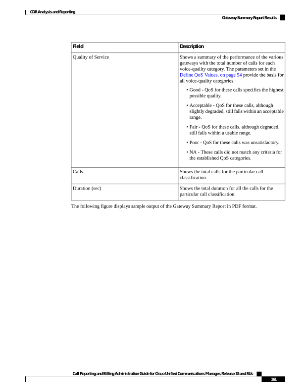
Page 174
Figure 27: Gateway Summary Report
Gateway and Route Utilization Report Results
The Gateway, Route Group, Route List, and Route Pattern Utilization reports provide similar output. If you
choose to display the report in PDF format, the report shows the utilization as a bar chart. A graph displays
for each selected gateway or route group. See the table.
Table 72: Gateway and Route Utilization Report Fields
Description
Field
Time in one-hour blocks if you chose Hourly or
one-day blocks if you chose weekly or monthly. The
results show the utilization for each hour or day for
the entire period that is shown in the from and to dates.
Time/Day
Gateway, route group, route list, or route pattern
utilization percentage. This field gives the estimated
utilization percentage of the gateways or route groups
or route lists or route patterns relative to the total
number of calls that all the gateways put together can
support at any one time.
%
Call Reporting and Billing Administration Guide for Cisco Unified Communications Manager, Release 15 and SUs
162
CDR Analysis and Reporting
Gateway and Route Utilization Report Results
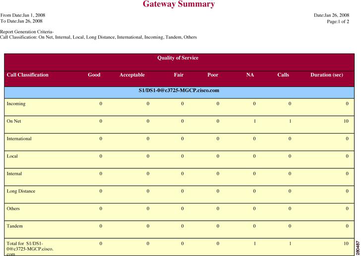
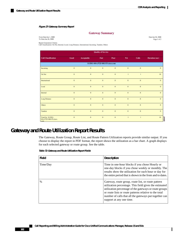
Page 175
Figure 28: Gateway Utilization Report, on page 163 displays sample output of the Gateway Utilization Report
in PDF format.
Figure 28: Gateway Utilization Report
Figure 29: Route/Hunt List Utilization Report, on page 164 displays sample output of the Route/Hunt List
Utilization report in PDF format.
Call Reporting and Billing Administration Guide for Cisco Unified Communications Manager, Release 15 and SUs
163
CDR Analysis and Reporting
Gateway and Route Utilization Report Results
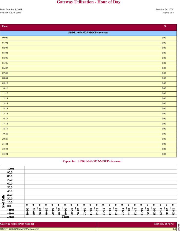
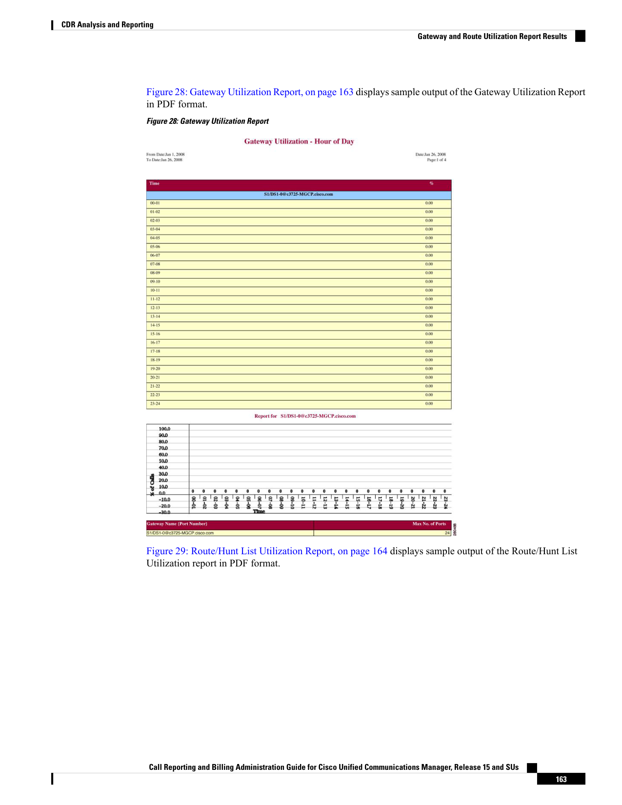
Page 176
Figure 29: Route/Hunt List Utilization Report
Figure 30: Route and Line Group Utilization Report, on page 165 displays sample output from the Route and
Line Group Utilization report in PDF format.
Call Reporting and Billing Administration Guide for Cisco Unified Communications Manager, Release 15 and SUs
164
CDR Analysis and Reporting
Gateway and Route Utilization Report Results
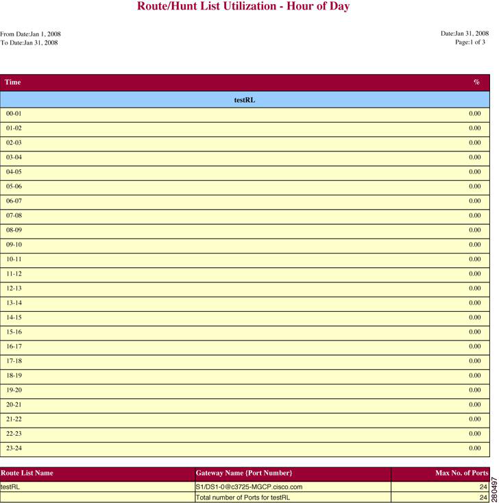
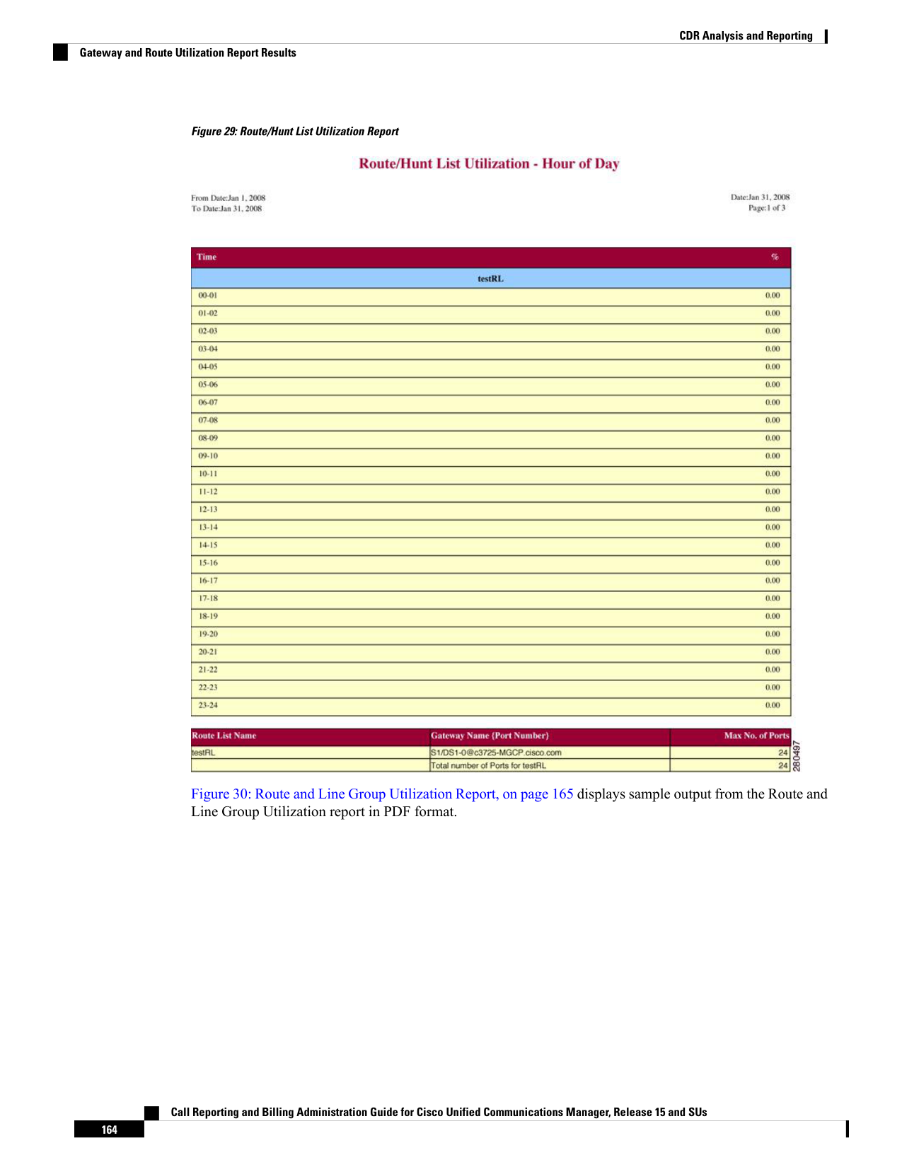
Page 177
Figure 30: Route and Line Group Utilization Report
Figure 31: Route Pattern/Hunt Path Utilization Report, on page 166 displays sample output of the Route
Pattern/Hunt Path Utilization report in PDF format.
Call Reporting and Billing Administration Guide for Cisco Unified Communications Manager, Release 15 and SUs
165
CDR Analysis and Reporting
Gateway and Route Utilization Report Results
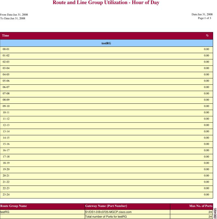
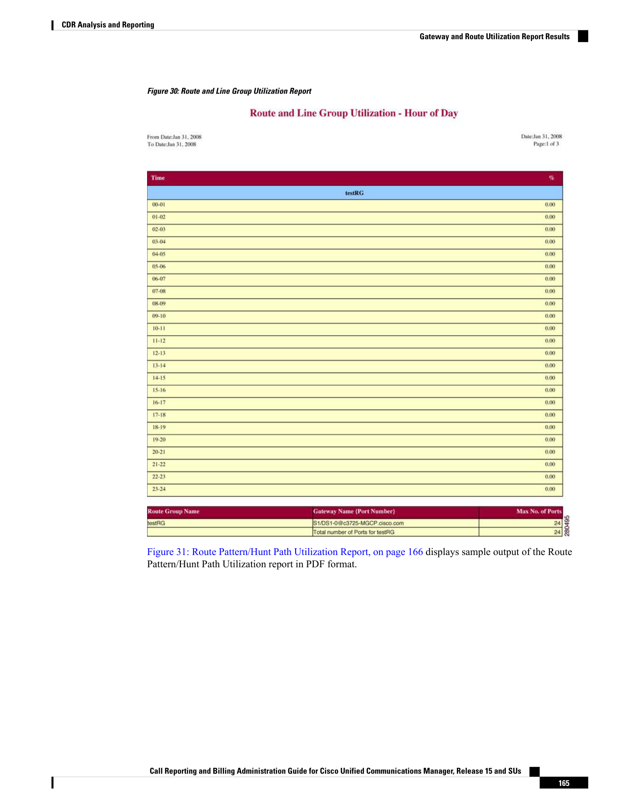
Page 178
Figure 31: Route Pattern/Hunt Path Utilization Report
Hunt Pilot Summary Report Results
The Hunt Pilot Summary report includes the following fields. See the table.
Table 73: Hunt Pilot Summary Report Fields
Description
Field
Time in one-hour blocks if you chose Hourly or
one-day blocks if you chose weekly or monthly. The
results show the call details for each hour or day for
the entire period that is shown in the from and to dates.
Time
Call Reporting and Billing Administration Guide for Cisco Unified Communications Manager, Release 15 and SUs
166
CDR Analysis and Reporting
Hunt Pilot Summary Report Results
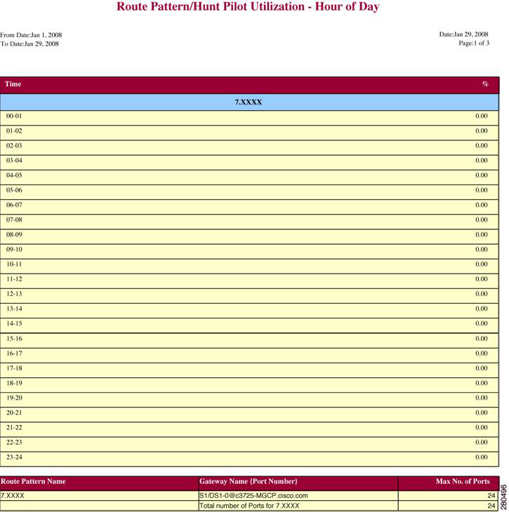
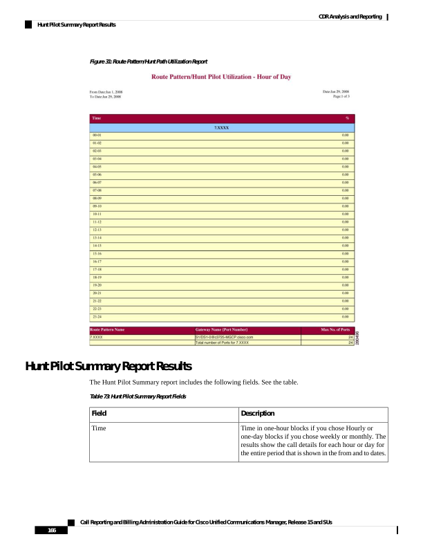
Page 179
Description
Field
Number of calls presented and received at the
specified time duration/day.
Number of calls received = Number of calls handled
- Number of calls abandoned + Number of calls
Forwarded due to no Answer + Number of calls
Forwarded due to Busy + Number of calls Failed.
No.of Calls Presented/Received
Number of calls answered.
No.of Calls Handled/Answered
Number of calls that went on/off hook but were never
connected or answered.
No.of Calls Abandoned (Not Answered nor
Redirected)
Number of calls that were forwarded due to no reply.
No.of Calls Forwarded due to no Answer (FONA)
Number of calls that were forwarded since the
receiving end was busy.
No.of Calls Forwarded due to Busy (FOB)
Number of calls that failed to go through.
No.of Calls Failed
Lists the name of the available Hunt Pilots.
Hunt Pilot Name
List the line numbers of the hunt members.
Line Number
Figure 32: Hunt Pilot Summary Report, on page 168 displays sample output of the Hunt Pilot Summary report
in PDF format.
Call Reporting and Billing Administration Guide for Cisco Unified Communications Manager, Release 15 and SUs
167
CDR Analysis and Reporting
Hunt Pilot Summary Report Results
Page 180
Figure 32: Hunt Pilot Summary Report
Hunt Pilot Detail Report Results
The Hunt Pilot Detail report includes the following fields. See the table.
Table 74: Hunt Pilot Detail Report Fields
Description
Field
Date and Time when the call was received
Date/Time connected
Date and Time when the call ended
Date/Time disconnected
Time duration of the call
Duration
Directory number (DN) of the caller
Calling Party
Call Reporting and Billing Administration Guide for Cisco Unified Communications Manager, Release 15 and SUs
168
CDR Analysis and Reporting
Hunt Pilot Detail Report Results
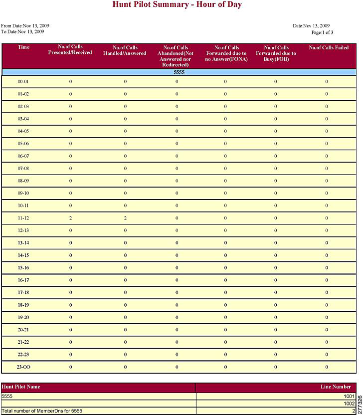
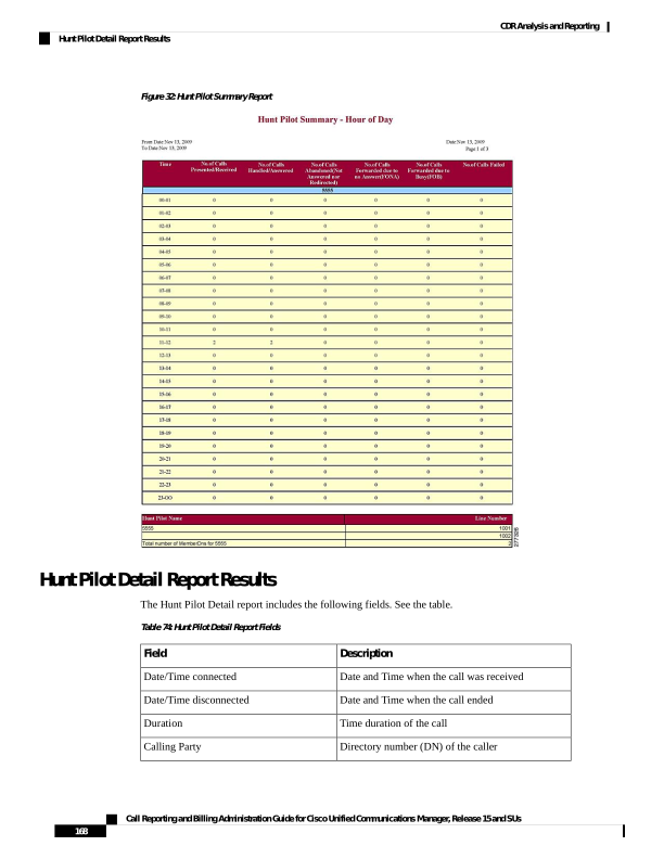
Page 181
Description
Field
Hunt Pilot Directory number (DN)
Called Party
Directory Number where the call landed in the end.
If the call is landed in Hunt Pilot, then it will show its
member DN. Suppose the call forward is set from
member DN to some other DN, it will show that DN
where the call got forwarded.
The number of the hunt member is displayed only
when the Show Line Group Member DN in
finalCalledPartyNumber CDR Field is set to true. If
the value is set to false, the Hunt Pilot DN is displayed
in this field. For details on setting this parameter see,
Service Parameters Configuration in Cisco Unified
CM Administration Guide.
Final Called Party Number
Device identifier of the device that answered the call.
Dest. Device Name
Indicates if the call was answered or not. Values could
be Yes or No.
Call Answered
Indicates if the call was abandoned. Values could be
Yes or No.
Call Abandoned
Indicates if the call was forwarded due to no reply.
Values could be Yes or No.
Call Forwarded Due to No Answer (FONA)
Indicates if the call was forwarded since the answering
end was busy. Values could be Yes or No.
Call Forwarded Due to Busy (FOB)
Indicates if the call failed to get through. Values could
be Yes or No.
Call Failed
Identification number to trace the call. This is the
globalcallid_callid value in the CDR database.
Call Reference
Figure 33: Hunt Pilot Details Report, on page 169 displays sample output of the Hunt Pilot Details report in
the PDF format.
Figure 33: Hunt Pilot Details Report
Call Reporting and Billing Administration Guide for Cisco Unified Communications Manager, Release 15 and SUs
169
CDR Analysis and Reporting
Hunt Pilot Detail Report Results
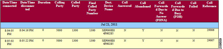
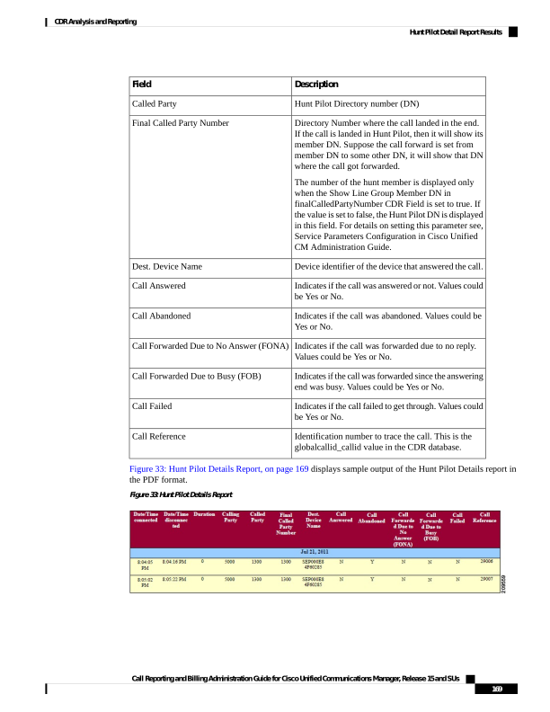
Page 182
Conference Call Detail Report Results
You can choose to generate Conference Call information in either a summary or a detailed report. The reports
display the call details in a table when you generate the report in PDF format. The following tables show the
fields in the Conference Call Detail and Summary reports. See the tables.
The report criteria include the type of conference (ad hoc and/or meet-me) and the From and To date range.
Note
Table 75: Conference Call Detail Summary Report Fields
Description
Field
Time that the first participant enters the conference.
Orig. Time
Time that the last participant leaves the conference.
Term. Time
Number of participants in the conference.
No. of Participants
Sum of the duration of individual participants in the conference
in seconds.
Duration
Names of the conference devices that were used.
Device Name
Table 76: Conference Call Detail Report Fields
Description
Field
Time at which conference started.
Conference Start Time
Time at which conference ended.
Conference End Time
Time at which conference participants connected to
conference.
Connect Time
Time at which conference participants disconnected from
conference.
Disconnect Time
Total time of conference.
Duration
Directory number of participants.
Directory Number
Call types of conference (internal, incoming, and so on.)
Call Classification
Names of the conference devices that were used.
Device Name
Quality of service.
QoS
Figure 34: Conference Call Details Summary Report, on page 171 displays sample output of the Conference
Call Details Summary report in PDF format.
Call Reporting and Billing Administration Guide for Cisco Unified Communications Manager, Release 15 and SUs
170
CDR Analysis and Reporting
Conference Call Detail Report Results

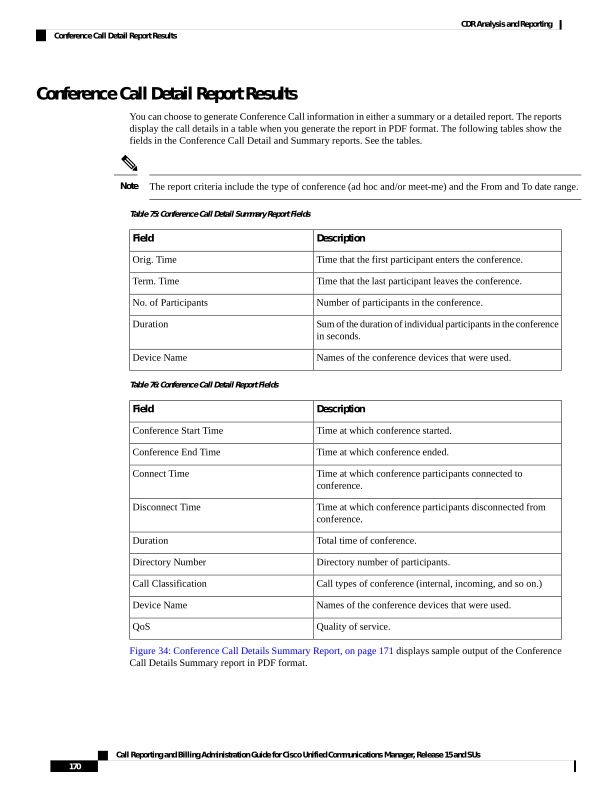
Page 183
Figure 34: Conference Call Details Summary Report
Conference Bridge Utilization Report Results
The Conference Bridge Utilization report provides the following fields. If you choose PDF format, the report
shows the utilization as a table. See the table.
Table 77: Conference Bridge Utilization Report Fields
Description
Field
Time in one-hour blocks if you chose Hourly or
one-day blocks if you chose day of week or daily.
Time/Day
Conference bridge utilization percentage.
% Usage
The conference bridge device that is used to hold
conference calls.
Conf. Bridge
Either hardware or software conference bridge.
Type
The number of conferences that can be held at a time
along with the number of people per conference.
Max Streams
Figure 35: Conference Bridge Utilization Report, on page 172 displays sample output of the Conference Bridge
Utilization report in PDF format.
Call Reporting and Billing Administration Guide for Cisco Unified Communications Manager, Release 15 and SUs
171
CDR Analysis and Reporting
Conference Bridge Utilization Report Results
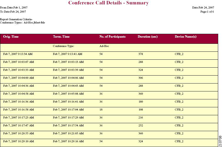
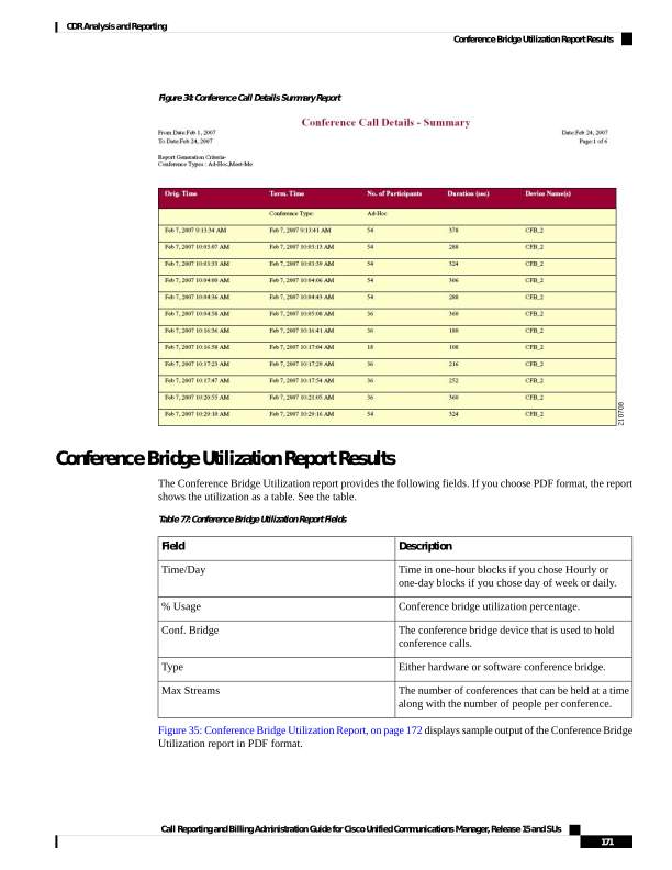
Page 184
Figure 35: Conference Bridge Utilization Report
Voice Messaging Utilization Report Results
The Voice Messaging Utilization report provides the following fields. See the table.
Table 78: Voice Messaging Utilization Report Fields
Description
Field
Time in one-hour blocks if you chose Hourly or
one-day blocks if you chose day of week or daily.
Time/Day
Voice-messaging percentage.
% Usage
Call Reporting and Billing Administration Guide for Cisco Unified Communications Manager, Release 15 and SUs
172
CDR Analysis and Reporting
Voice Messaging Utilization Report Results
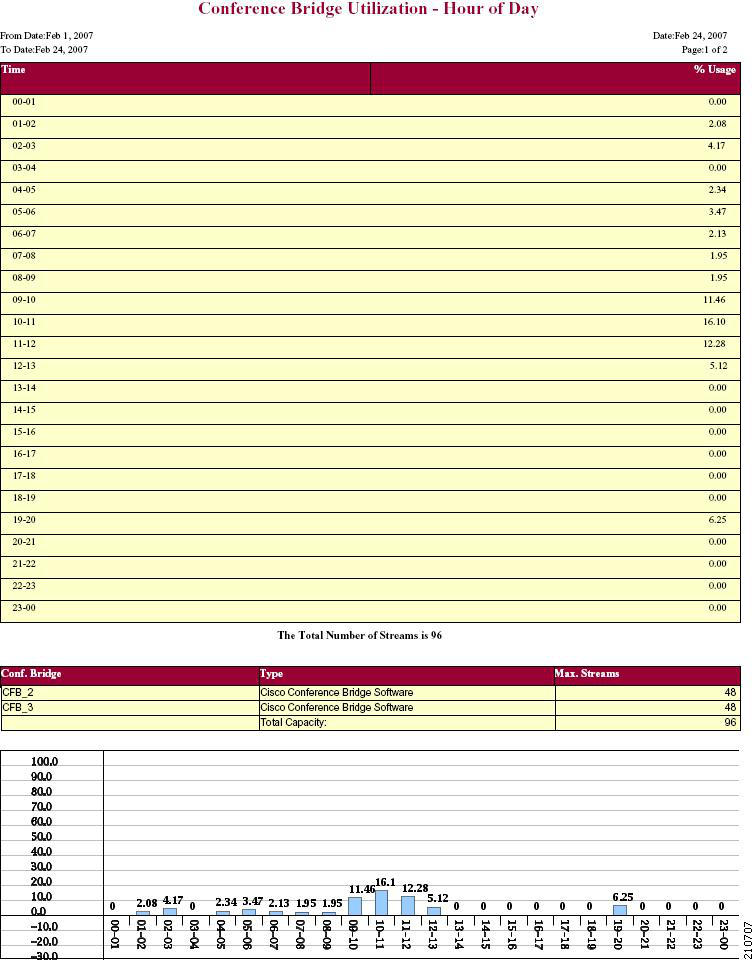
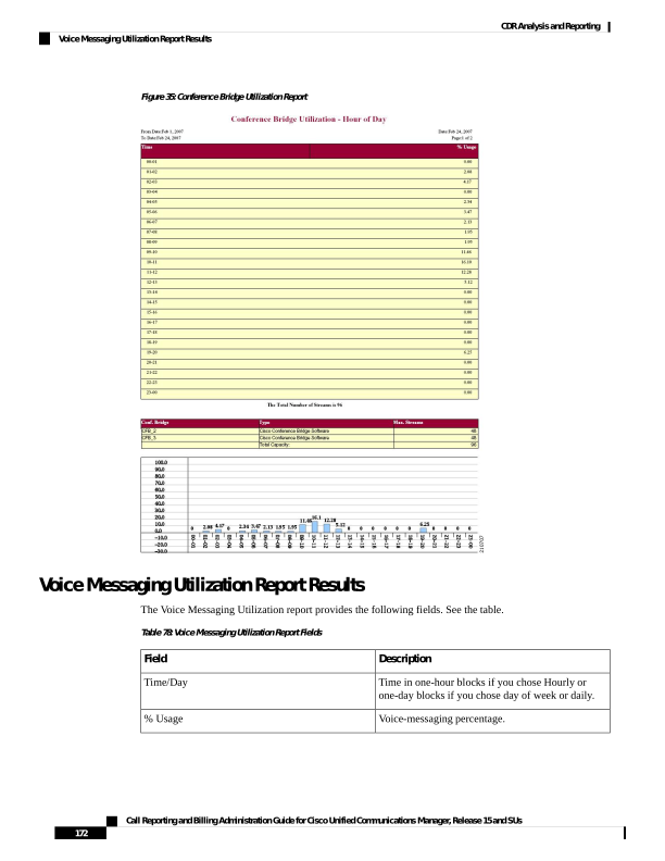
Page 185
Description
Field
The sum of the maximum number of ports for all the
gateways under the route patterns that are configured
for the voice-messaging systems and the entries in the
Device table of Unified Communications Manager
that have type Class as 8.
Voice Messaging Ports
The originating or destination device name of the
gateways under the route patterns that are configured
for the voice-messaging systems.
Voice Messaging Gateways
The number of ports that the voice-messaging gateway
supports.
Number of Ports
Figure 36: Voice Messaging Utilization Report, on page 173 displays sample output of the Voice Messaging
Utilization report in PDF format.
Figure 36: Voice Messaging Utilization Report
Call Reporting and Billing Administration Guide for Cisco Unified Communications Manager, Release 15 and SUs
173
CDR Analysis and Reporting
Voice Messaging Utilization Report Results
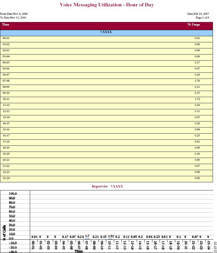
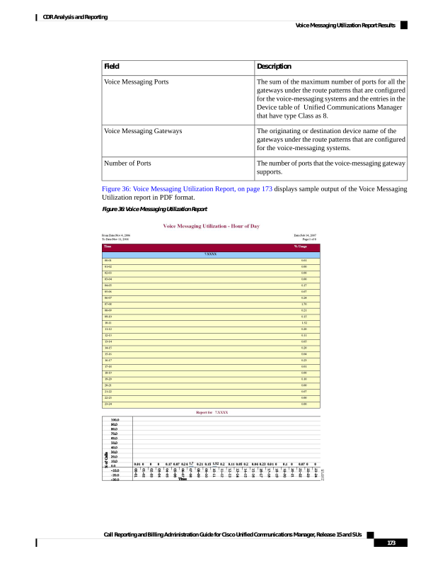
Page 186
Trunk Utilization Report Results
The Trunk Utilization report provides the following fields. If you choose to display the report in PDF format,
the report shows the utilization as a bar chart. A graph displays for each selected trunk. See the table.
Table 79: Trunk Utilization Report Fields
Description
Field
Time in one-hour blocks if you chose Hourly or
one-day blocks if you chose weekly or monthly. The
results show the utilization for each hour or day for
the entire period that is shown in the from and to dates.
Time/Day
Trunk utilization percentage. This field gives the
estimated utilization of the trunks relative to the total
number of calls that passed through the devices.
%
Figure 37: Trunk Utilization Report Sample 1, on page 175 to Figure 40: Trunk Utilization Report Sample 4,
on page 178 display sample output pages of the Trunk Utilization Report in PDF format.
Call Reporting and Billing Administration Guide for Cisco Unified Communications Manager, Release 15 and SUs
174
CDR Analysis and Reporting
Trunk Utilization Report Results
Page 187
Figure 37: Trunk Utilization Report Sample 1
Call Reporting and Billing Administration Guide for Cisco Unified Communications Manager, Release 15 and SUs
175
CDR Analysis and Reporting
Trunk Utilization Report Results
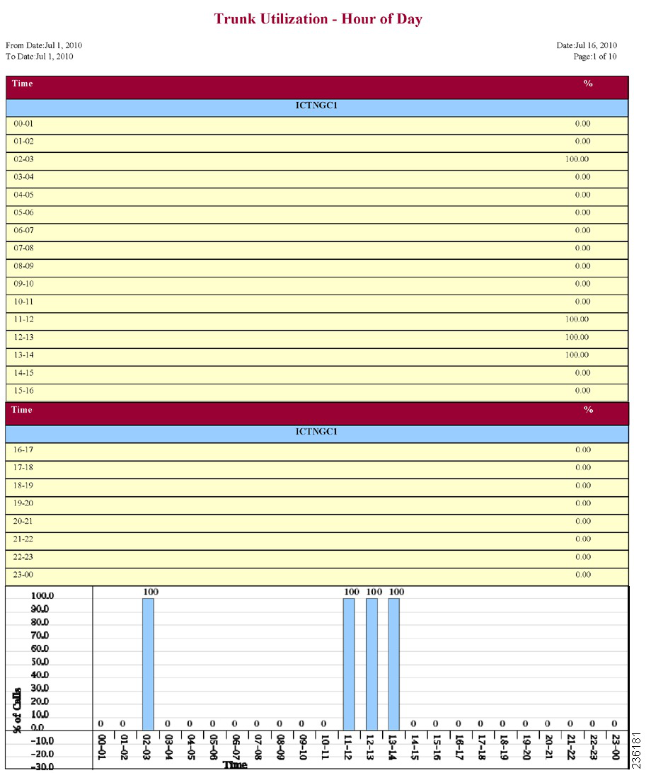
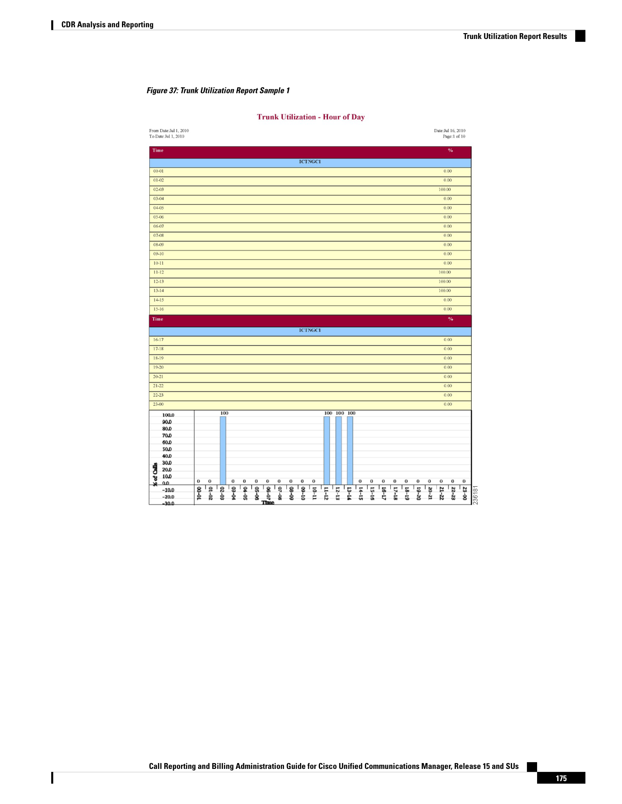
Page 188
Figure 38: Trunk Utilization Report Sample 2
Call Reporting and Billing Administration Guide for Cisco Unified Communications Manager, Release 15 and SUs
176
CDR Analysis and Reporting
Trunk Utilization Report Results
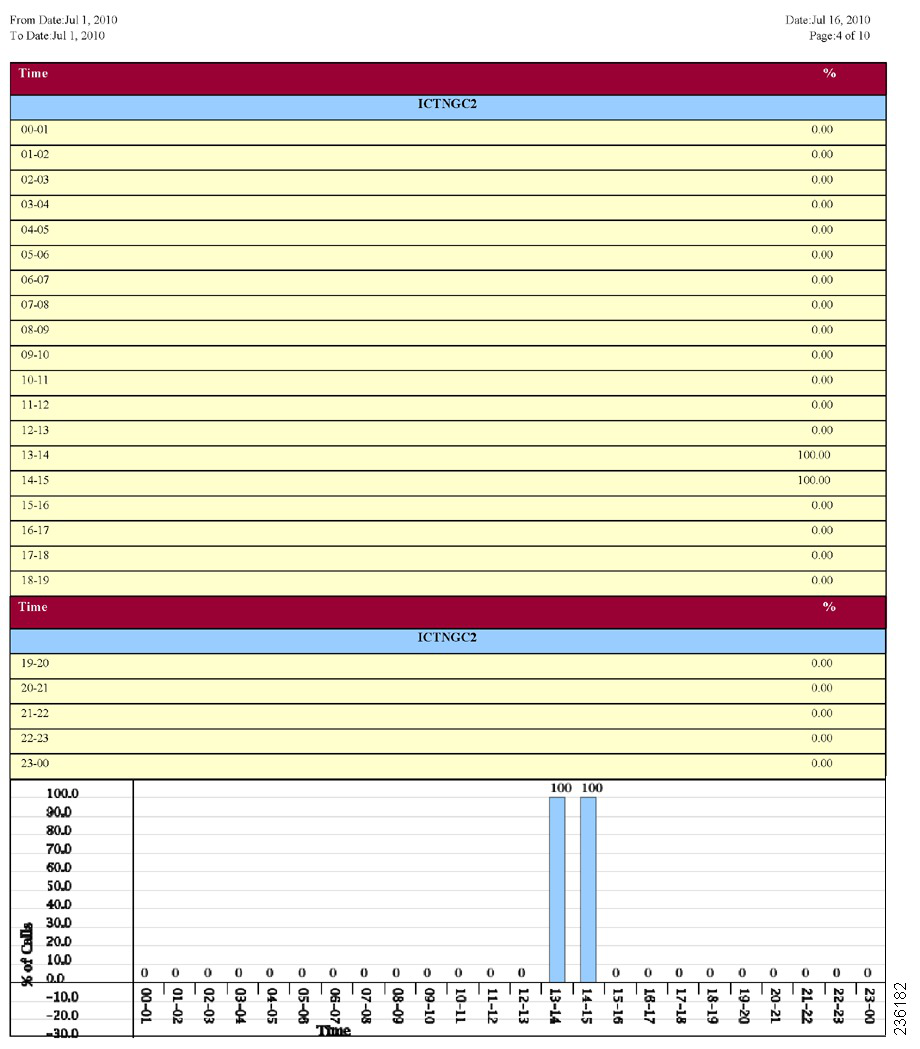
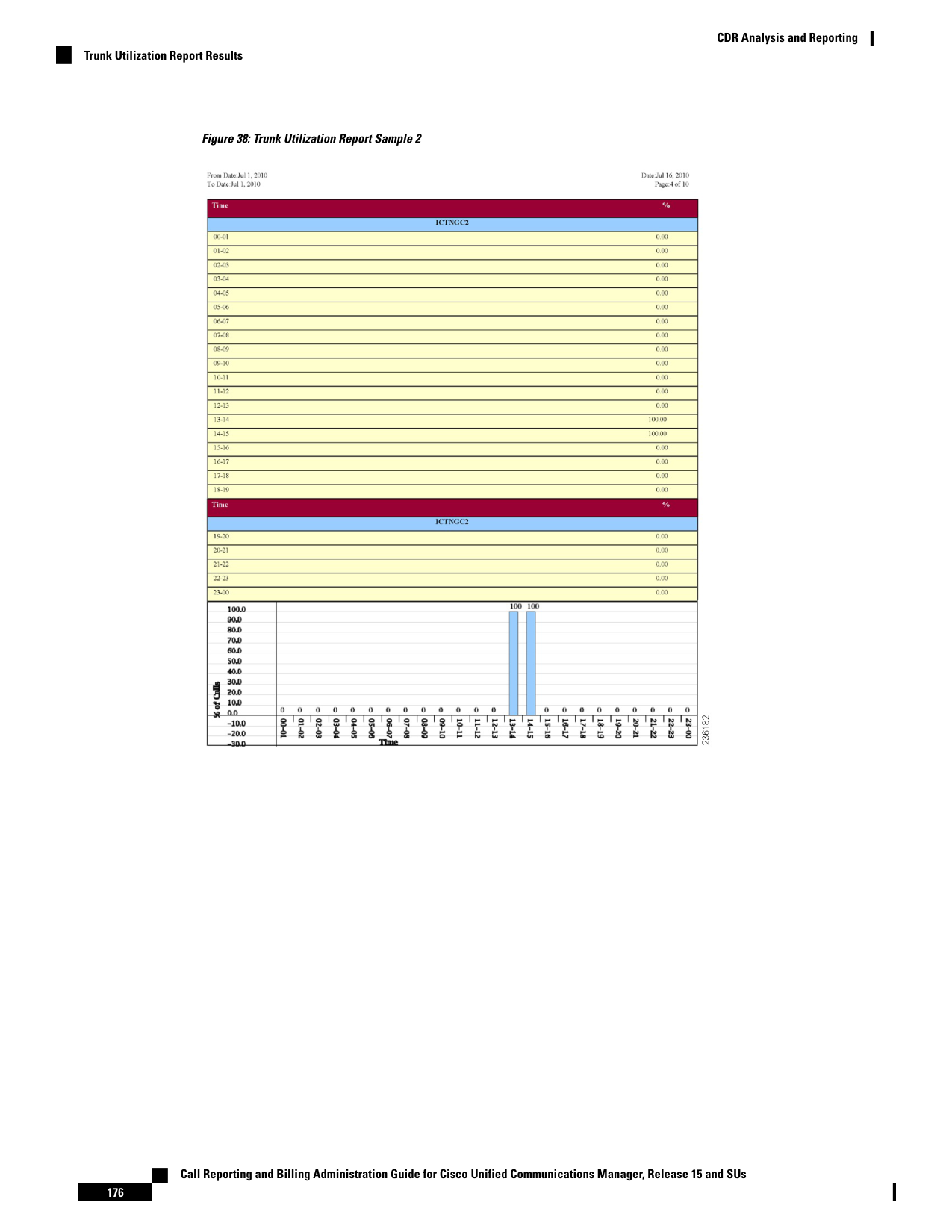
Page 189
Figure 39: Trunk Utilization Report Sample 3
Call Reporting and Billing Administration Guide for Cisco Unified Communications Manager, Release 15 and SUs
177
CDR Analysis and Reporting
Trunk Utilization Report Results
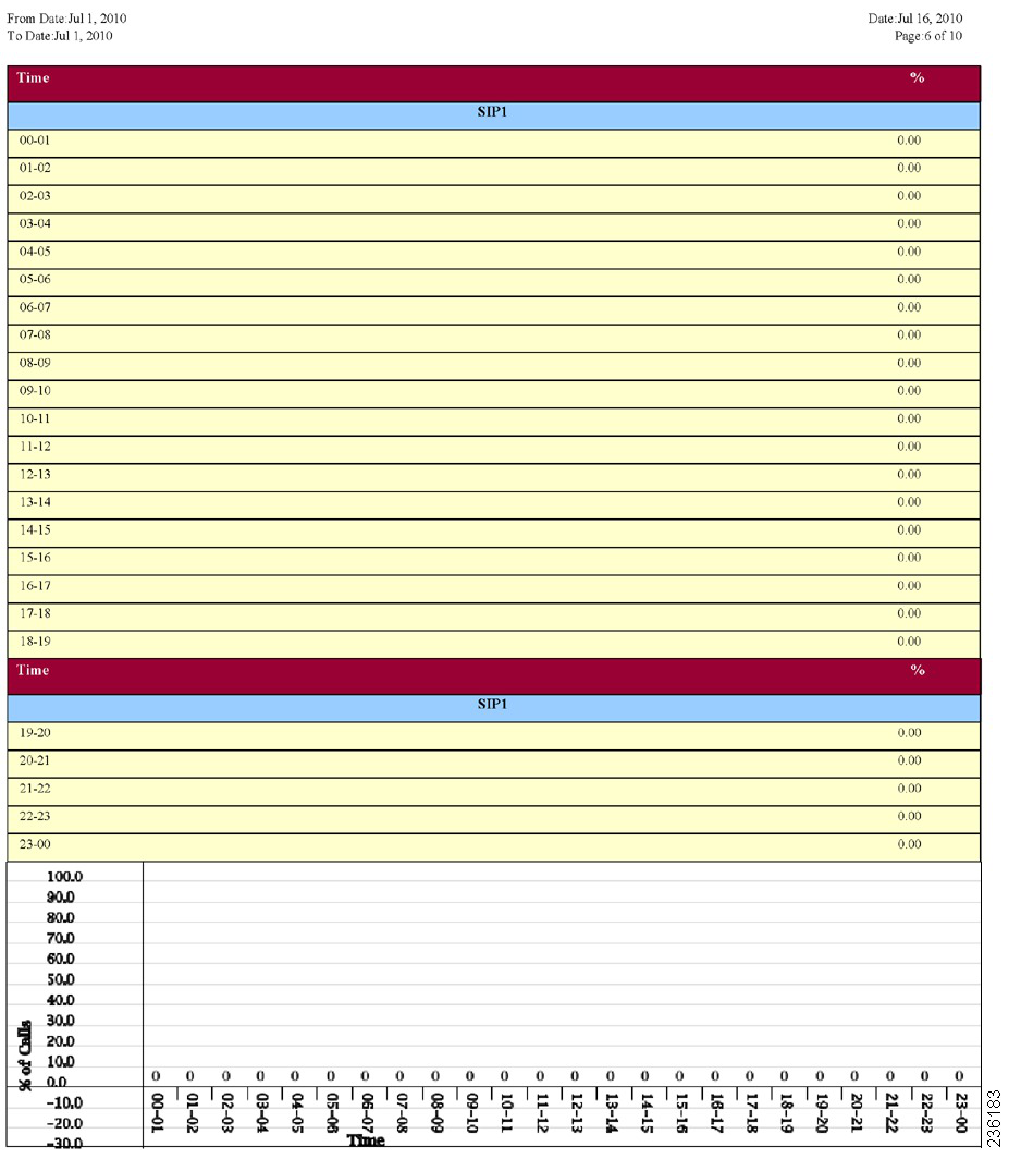
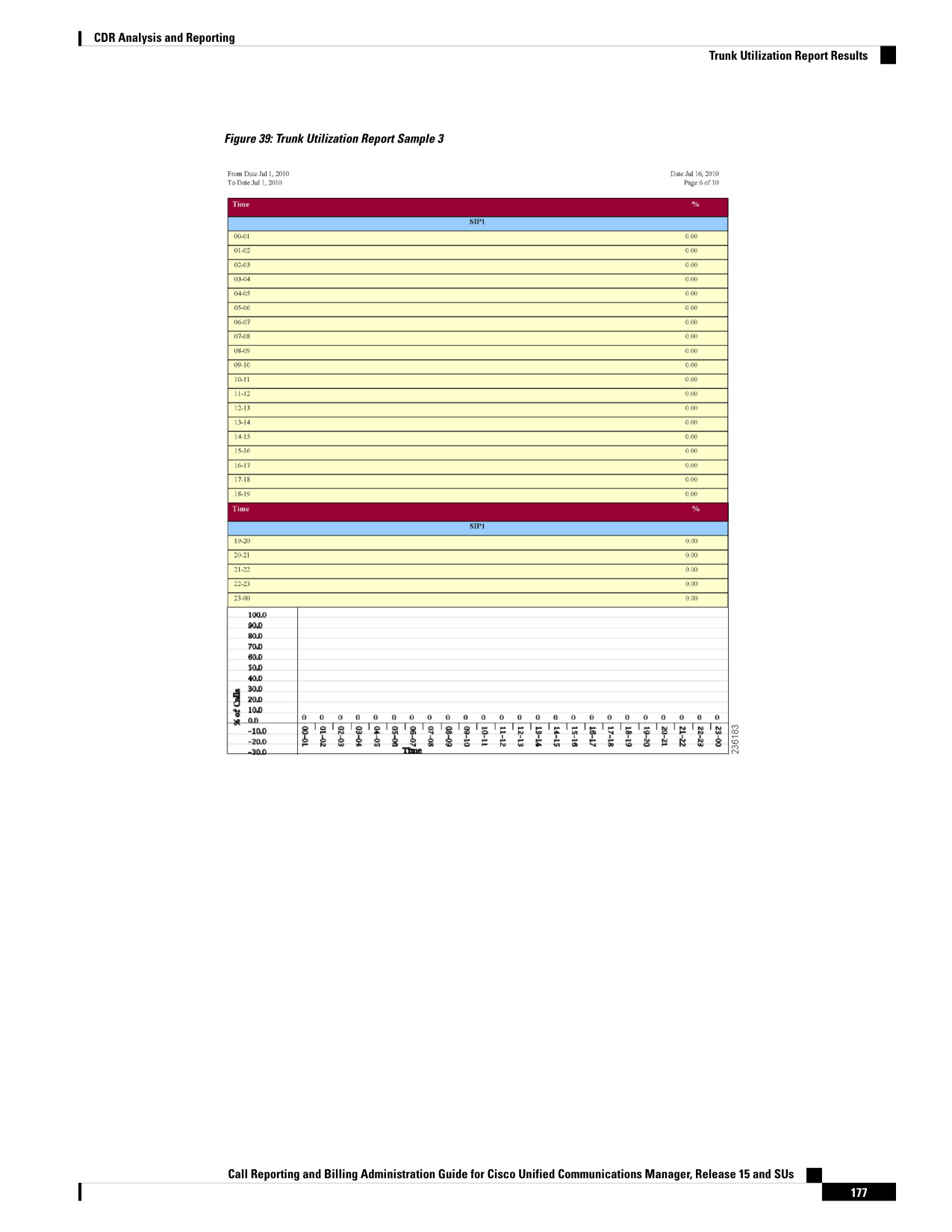
Page 190
Figure 40: Trunk Utilization Report Sample 4
Call Reporting and Billing Administration Guide for Cisco Unified Communications Manager, Release 15 and SUs
178
CDR Analysis and Reporting
Trunk Utilization Report Results
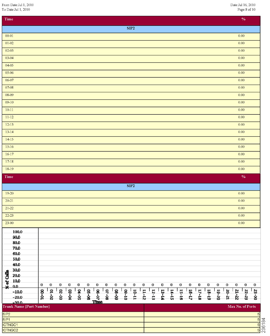
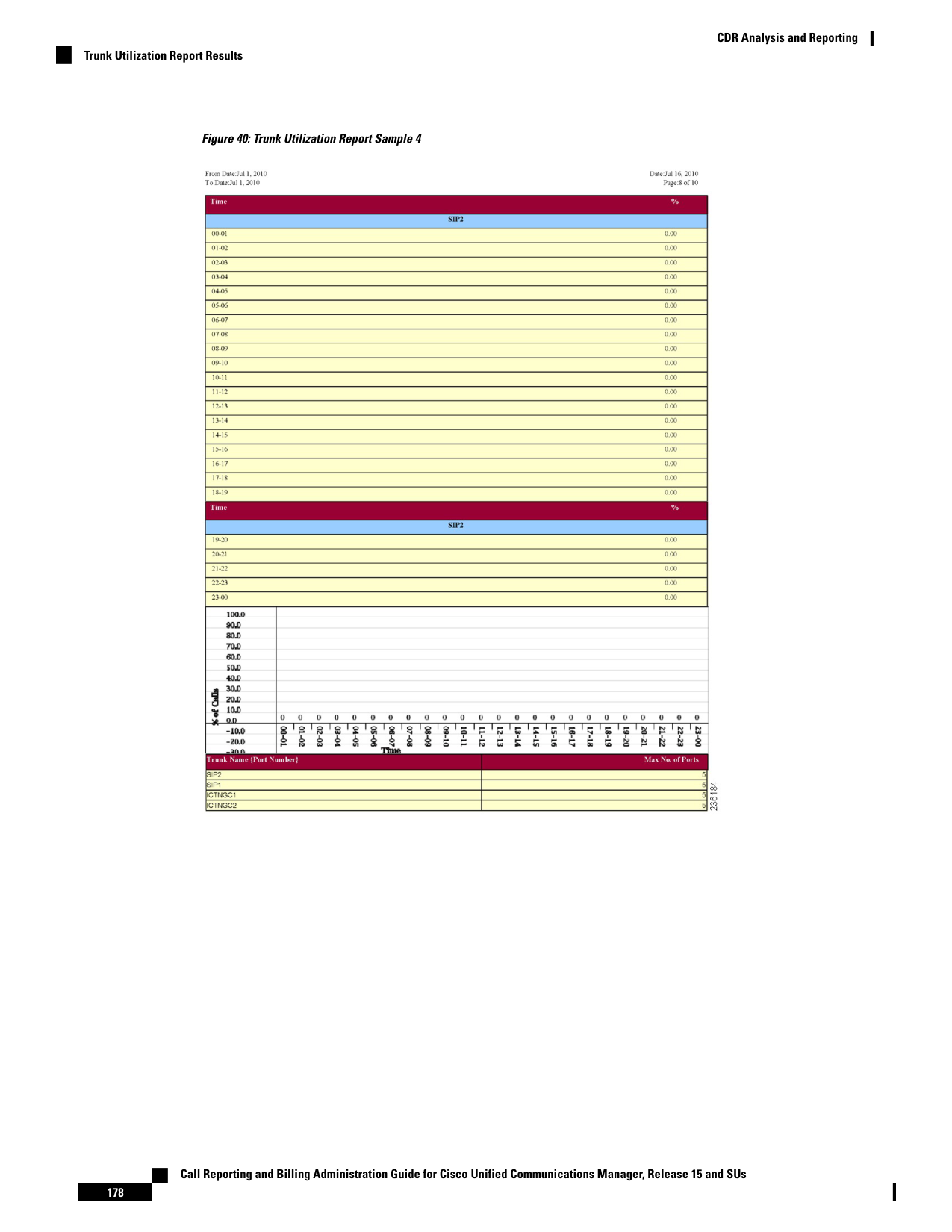
Page 191
C H A P T E R 7
Export CDRs and CMRs
• CDR and CMR Records, on page 179
• CDR Search, on page 182
• CDR Search Results, on page 196
CDR and CMR Records
This chapter describes how to export CDR/CMR records and how to view the exported records.
Use Export CDR/CMR in the CDR menu in Cisco Unified Communications Manager CDR Analysis and
Reporting to export CDR/CMR dump information to the location of your choice on your computer. The
CDR/CMR dump exists in the CSV format. You can also view the dump of the exported records.
Export CDR and CMR Records
Follow this procedure to export CDR and CMR record results.
Procedure
Step 1
From CDR Analysis and Reporting, choose CDR > Export CDR/CMR.
The Export CDR/CMR records window appears.
Step 2
In the From Date and To Date drop-down list boxes, choose a date range for the CDR/CMR dump.
Step 3
In Select records, check the CDR records and/or CMR records check box.
Step 4
Click Export to File.
The Export CDR/CMR records Result window appears. See the View CDR and CMR Records Results, on
page 179.
View CDR and CMR Records Results
The following procedure describes how to view Export CDR/CMR record results.
Call Reporting and Billing Administration Guide for Cisco Unified Communications Manager, Release 15 and SUs
179

Page 192
Before you begin
Before you begin the following procedure, perform all the steps in the Export CDR and CMR Records, on
page 179.
Procedure
Step 1
From the Export CDR/CMR Record Results window, right-click either the CDR Dump or CMR Dump link.
A popup window that comprises the following options displays:
a)
Open - This option allows you to open the window that contains the CDR/CMR dump in the same window.
b) Open in a New Window - This option allows you to open the window that contains the CDR/CMR dump
in a new window.
c)
Save Target As... - This option allows you to save the CDR/CMR dump to a location on your computer.
d) Print Target - This option allows you to print the CDR/CMR dump information.
e)
Copy Shortcut - This option allows you to copy the window shortcut to paste in another file.
f)
Add to Favorites - This option allows you to add the CDR/CMR dump to your Favorites folder.
g) Properties - This option provides the properties of the CDR/CMR dump file.
Step 2
From the pop-up window, choose one of the options.
Step 3
If you chose to save the CDR/CMR dump to your computer, choose a location in which to save the dump and
click Save. After the download is complete, you can locate the file wherever you download it to open it.
Step 4
To delete the CDR and/or CMR dump, check Delete File check box and click Back or Close.
The files get deleted.
Note
If you do not check the Delete File check box(es) (for example, if the CDR or CMR dump files get left
undeleted), the background process deletes the files daily. Because the CDR and CMR dump files are large,
Cisco recommends that you download the file to a local disk and delete them from the server to avoid the disk
usage on the server side.
CDR Data
Call detail records (CDRs) detail the called number, the number that places the call, the date and time that the
call starts, the time that the call connects, and the time that the call ends. Call management records (CMRs),
or diagnostic records, detail the jitter, lost packets, the amount of data sent and received during the call, and
latency. CDR data comprises CDRs and CMRs collectively. A single call can result in the generation of several
CDRs and CMRs. Unified Communications Manager records information regarding each call in CDRs and
CMRs. CDRs and CMRs, known collectively as CDR data, serve as the basic information source for CAR.
The Cisco CDR Agent service transfers CDR and CMR files that Unified Communications Manager generates
from the local host to the CDR repository node, where the CDR Repository Manager service runs over a SFTP
connection. If the SFTP connection fails, the Cisco CDR Agent services continue to make connection attempts
to the CDR repository node until a connection is made. The CiscoCDR Agent service sends any accumulated
CDR files when the connection to the CDR Repository node resumes. The CDR Repository Manager service
maintains the CDR and CMR files, allocates the amount of disk space for use by CMRs and CDRs, sends the
Call Reporting and Billing Administration Guide for Cisco Unified Communications Manager, Release 15 and SUs
180
CDR Analysis and Reporting
CDR Data
Page 193
files to up to three configured destinations, and tracks the delivery result for each destination. CAR accesses
the CDR/CMR files in the directory structure that the CDR Repository Manager service creates.
The high and low water mark settings that you configure specify percentages of the total disk space that are
allocated for the CDR repository. Although the preserved folder under the CDR repository folder contributes
to the high and low water mark percentages, Log Partition Monitoring never deletes the folder if the high
water mark gets reached. If the high water mark gets reached, the CDR Repository Manager deletes processed
CDR files until the low water mark is reached or all processed files are deleted, whichever comes first. If all
processed CDR files are deleted but the low water mark has not been reached, the deletion stops. The
CDRHighWaterMarkExceeded alarm gets generated until the system reaches the maximum disk allocation.
If the maximum disk allocation gets reached, the system deletes undelivered files, and files within the
preservation duration, starting with the oldest files, until disk utilization falls below the high water mark. If
you receive the CDRMaximumDiskSpaceExceeded alarm repeatedly for this scenario, either increase the disk
allocation or lower the number of preservation days.
When the disk allocation usage exceeds the configured high water mark threshold value, LMP also purges
the CDR and CMR data that are exported at the following path automatically:
/var/log/active/tomcat/logs/car/carreports/reports/ondemand/temp.
Customers or any third-party applications should ensure to retrieve the exported files immediately to avoid
losing their buffered historical data.
Note
Information on these alarms is found in the CDR Repository Alarm Catalog (CDRRepAlarmCatalog). The
following table displays the alarms and alerts in this catalog.
To configure these alarms, go to Cisco Unified Serviceability > Alarm > Configuration > CDR Services.
Table 80: CDR Repository Alarm Catalog
Description
Severity
Name
SFTP delivery of CDR files to the
outside billing server failed.
ERROR_ALARM
CDRFileDeliveryFailed
The CDR Agent cannot send CDR
files from the Cisco Unified CM
node to the CDR Repository node
within the Unified
Communications Manager cluster.
ERROR_ALARM
CDRAgentSendFileFailed
The high water mark (HWM) for
CDR files was reached; some
successfully delivered CDR files
have been deleted.
WARNING_ALARM
CDRHWMExceeded
The CDR files disk usage exceeded
the maximum disk allocation. Some
undelivered files may have been
deleted to bring disk usage down.
CRITICAL_ALARM
CDRMaximumDiskSpaceExceeded
SFTP delivery of CDR files failed
on retries.
ERROR_ALARM
CDRFileDeliveryFailureContinues
Call Reporting and Billing Administration Guide for Cisco Unified Communications Manager, Release 15 and SUs
181
CDR Analysis and Reporting
CDR Data

Page 194
Description
Severity
Name
The CDR Agent cannot send CDR
files from the Cisco Unified CM
node to the CDR Repository node
on retries.
ERROR_ALARM
CDRAgentSendFileFailureContinues
For additional information on these alarms and recommended action, see the alarm definitions at Cisco Unified
Serviceability > Alarm > Definitions > CDRRepAlarmCatalog.
For more information on CDR services and alarms, see the Cisco Unified Serviceability Administration Guide.
CDR Search
In all CDR Search reports, the system only displays the oldest 100 records that fall into the time and date
range that you configure. The CDR Search reports generate only in HTML format.
You can configure CDR searches to verify the details of a call. The search forms groups of all the related legs
of a call, which can be useful if the call involves a conference or transfer. This method helps you track the
progress and quality of each part of an entire call.
This section describes the following features:
• CDR Search by User/Phone Number/SIP URL - Available for CAR administrators. You can search CDRs
by the user or directory number (calling, original called, final called, or bridge number) to analyze call
details for the first 100 records that satisfy the search criteria. You can search for calls by using specific
numbers for the period that you specify, which helps you trace calls that are placed from or to any specific
numbers for diagnostic or informational purposes. All associated records, such as transfer and conference
calls, appear together as a logical group. If you do not specify the phone number or SIP URL, the system
returns the first 100 CDR records that match the date range that you specify.
• CDR Search by Gateway - Available for CAR administrators. You can search CDRs by gateways to
analyze the call details of calls that are using specific gateways. This method helps you trace issues on
calls through specific gateways.
• CDR Search by Cause for Call Termination - Available for CAR administrators. You can search CDRs
by cause for call termination to get information about the cause for the termination of a call. You can
choose from a list of causes for call termination and can generate the report for a particular date range.
The generated report contains the report criteria, along with the total number of calls that were placed
in the given time. In addition, a table displays with the fields Call Termination Cause Value and
description, the total number of calls, and the percentage of calls for each Call Termination Cause, and
an option to choose the CDRs.
• CDR Search by Call Precedence Level - Available for CAR administrators. You can search CDRs by
call precedence level. The report that generates allows you to view the CDRs on the basis of precedence.
You can choose the precedence level and date range for which to generate a report. The report displays
the number of calls and the percentage of these calls for each precedence level that you choose. Report
criteria display the precedence levels and date range for which the report-generated information in the
Call Precedence Details window. You can view the media information and the CDR-CMR dump from
the CDR Search by Precedence Levels Result window. The media information and CDR-CMR dump
information display in separate windows.
Call Reporting and Billing Administration Guide for Cisco Unified Communications Manager, Release 15 and SUs
182
CDR Analysis and Reporting
CDR Search
Page 195
• CDR Search for Malicious Calls - Available for CAR administrators. You can search for CDRs to get
information about malicious calls. You can choose phone number or SIP URL and the date range for
which to generate a report. The report displays the CDRs for all the malicious calls for a chosen phone
number or SIP URL and date range. Report criteria display the phone number or SIP URL and the date
range for which the report-generated information. You can view the media information and CDR-CMR
dump from the CDR-CMR search results window. The media information and CDR-CMR dump
information display in separate windows.
• Export CDR/CMR - Available for CAR administrators. With this feature, you can export CDR/CMR
dump information, for a given date range in the CSV format, to a location that you choose on your
computer. You can also view the file size of the dump information and delete CDR/CMR files.
CAR provides reporting capabilities for three levels of users: administrators, managers, and individual users.
However, only CAR administrators can use CDR Search.
Note
Before You Begin
Make sure that you set the Unified Communications Manager service parameters CDR Enabled Flag and Call
Diagnostics Enabled to True (enabled), so the system can generate CDR/CMR data. By default, the system
disables these service parameters. For more information about these service parameters, see the Configure
CDR Service Parameters, on page 24.
All CAR reports use CDR data. Be sure to have the most current CDR data from which to build your reports.
By default, CDR data loads continuously 24 hours a day, 7 days a week. However, you can set the loading
time, interval, and duration as needed. For more information, see Set Up CDR Load Schedule, on page 36.
After you log in to the CAR main window, the following warning may display if Unified Communications
Manager is also activated: “Warning: In some servers in this cluster the CDR Enabled Flag is false and so
CDR entries may not be generated for all the calls that are made in this cluster.” Some clusters have multiple
nodes where some of the nodes do not run Unified Communications Manager services. This warning checks
all nodes in the cluster regardless of Unified Communications Manager service activation status. Ignore the
warning after manually checking the CDR Enabled Flag parameter settings for all the Unified Communications
Manager service subscribers.
Note
Generate CDR Search by User
Only CAR administrators use the CDR Search by User/Phone Number/SIP URL feature.
This section describes how to show the details of CDR data based on a user or phone number or SIP URL
feature. You can search CDR data by user or directory number (calling, original called, or final called) to
analyze call details for the oldest 100 records that satisfy the search criteria. If more than 100 records are
returned, the system truncates the results. You can search for calls by using specific numbers for the period
that you specify, which helps you trace calls that are placed from or to any specific numbers for diagnostic
or informational purposes. All associated records, such as transfer, mobility, silent monitoring and recording,
and conference calls, appear together as a logical group.
Call Reporting and Billing Administration Guide for Cisco Unified Communications Manager, Release 15 and SUs
183
CDR Analysis and Reporting
Generate CDR Search by User

Page 196
Procedure
Step 1
Choose CDR > Search > By User/Phone Number/SIP URL.
The CDR Search window displays.
Note
You can enter a wildcard pattern like “!” or “X” to search on phone number or SIP URL. The “!” represents
any n digit that has 0-9 as each of its digits, and the “X” represents a single digit in the range 0-9.
Step 2
Perform one of the following tasks:
a)
To search CDRs based on Internal Phone Number/SIP URLs, enter the value in the Phone Number/SIP
URL field and click Add Phone Number/SIP URL.
b) To search CDRs based on user, click the Search Internal Phone Number/SIP URL based User link,
enter the first few letters of the first and/or the last name in the First Name and/or the Last Name fields,
and click Search. When the results display, click the Select link next to the result that you want to include.
Click Close.
The phone number or SIP URL displays in the Phone Number/SIP URL(s) box.
Note
To delete an item from the Report Criteria box, click Remove Phone Number/SIP URL(s) . You can
delete all items from the Report Criteria box by clicking Remove All Phone Number/SIP URL(s) .
Step 3
Choose the date and time range of the period for which you want to see CDR data for the specified user or
phone number or SIP URL. The current time displays in both Coordinated Universal Time (UTC) and local
time and uses the following rules:
a)
The UTC and local time comprise a numeric string of mmddyyyy hhmmss, as in January 15, 2007 12:00:00.
b) The default FromDate and ToDate values display in UTC time.
c)
The default ToDate specifies the current time of the server in UTC time.
d) The default FromDate value specifies the ToDate value minus 1hour. For example, if ToDate = January
15, 2007 12:00:00, the FromDate default value = January 15, 2007 11:00:00 (all times in UTC).
Step 4
Choose whether to run the CDR Search report with grouping or without grouping. If you choose with grouping,
check the check box beside With Grouping. The default value specifies Without Grouping.
Note
With Grouping choice means that the system returns CDR records that match the date and time range for the
search, and groups them with their associated records. Without Grouping returns all the CDR records that
match the date and time range without grouping all the associated records for each call.
Step 5
Click OK.
The CDR-CMR Search Results window displays. The system only displays the oldest 100 records that fall
into the date range that you configured in Step 3, on page 184.
Step 6
To view the CMR data, click Others. To view both the CDR and CMR data fields, click View.
Step 7
To mail the report to e-mail recipient(s), follow the steps in the Mail Reports, on page 63.
Call Reporting and Billing Administration Guide for Cisco Unified Communications Manager, Release 15 and SUs
184
CDR Analysis and Reporting
Generate CDR Search by User
Page 197
Generate CDR Search by Gateway
Only CAR administrators use the CDR Search by Gateway feature.
This section describes how to search CDR data based on a specific gateway type or on those gateways that
use a chosen route pattern.
Procedure
Step 1
Choose CDR > Search > By Gateway.
The CDR Search by Gateway window displays.
Step 2
Perform one of the following tasks:
a)
To display all the gateways that are configured in the system, click Gateway Types in the Gateway Types
and Route Patterns pane.
b) To expand the tree structure and display the type of gateway from which you can choose, click the icon
next to Gateway types.
c)
To choose a gateway that uses a particular route pattern/hunt pilot, rather than a gateway type, click Route
Patterns/Hunt Pilots in the Gateway Types and Route Patterns pane. The gateways that are associated
with the configured Route Patterns/Hunt Pilots display.
d) To expand the tree structure and display route pattern/hunt pilot for you to choose, click the icon next to
Route Patterns/Hunt Pilots.
Note
You can also search for specific route patterns/hunt lists by entering part of the name of the route
pattern(s)/hunt pilot(s) in the Route Patterns/Hunt Pilots box in the column on the left side of the window.
CAR searches for the route pattern(s)/hunt list(s) that matches the search string.
Step 3
Choose a gateway type from the list.
The gateway name displays in the List of Gateways box.
Note
The List of Gateways box displays up to 200 gateways that are configured for the chosen gateway type.
Step 4
In the List of Gateways box, choose the gateways that you want to include in the report.
Note
You can generate a report for up to 15 gateways at a time. If you choose more than 15 gateways, you will
receive a message that states “Select 15 or fewer gateways to generate new report.”
Step 5
To move the chosen gateway to the list of Selected Gateways box, click the down arrow.
The gateway that you chose displays in the Selected Gateways box.
Step 6
Choose the date and time range of the period during which you want to search for CDR data. The current time
displays in both Coordinated Universal Time (UTC) and local time and uses the following rules:
a)
The UTC and local time comprise a numeric string of mmddyyyy hhmmss, as in January 15, 2007 12:00:00.
b) The default FromDate and ToDate values display in UTC time.
c)
The default ToDate specifies the current time of the server in UTC time.
Call Reporting and Billing Administration Guide for Cisco Unified Communications Manager, Release 15 and SUs
185
CDR Analysis and Reporting
Generate CDR Search by Gateway
Page 198
d) The default FromDate value specifies the ToDate value minus 1hour. For example, if ToDate = January
15, 2007 12:00:00, the FromDate default value = January 15, 2007 11:00:00 (all times in UTC).
Step 7
Choose whether to run the CDR Search report with grouping or without grouping. If you chose with grouping,
check the check box beside With Grouping. The default specifies Without Grouping.
Note
With Grouping choice means that the system returns CDR records that match the date and time range for the
search, and groups them with their associated records. Without Grouping returns all the CDR records that
match the date and time range without grouping all the associated records for each call.
Step 8
Click OK.
The CDR-CMR Results window displays. The system only displays the oldest 100 records that fall into the
date and time range that you configured in Step 6, on page 185. If more than 100 records are returned, the
system truncates the results.
Step 9
To view the CMR data, click Others . To view both the CDR and CMR data fields, click View.
Step 10
To mail the report to e-mail recipient(s), follow the steps in the Mail Reports, on page 63.
Generate CDR Search by Cause for Call Termination
Only CAR administrators use the CDR Search by Cause for Call Termination feature. The following tables
contain the call termination cause codes by which you may search.
Table 81: Call Termination Cause Codes
Description
Code
No error
0
Unallocated (unassigned) number
1
No route to specified transit network (national use)
2
No route to destination
3
Send special information tone
4
Misdialed trunk prefix (national use)
5
Channel unacceptable
6
Call awarded and being delivered in an established channel
7
Preemption
8
Preemption - circuit reserved for reuse
9
Normal call clearing
16
User busy
17
Call Reporting and Billing Administration Guide for Cisco Unified Communications Manager, Release 15 and SUs
186
CDR Analysis and Reporting
Generate CDR Search by Cause for Call Termination
Page 199
Description
Code
No user responding
18
No answer from user (user alerted)
19
Subscriber absent
20
Call rejected
21
Number changed
22
Non-selected user clearing
26
Destination out of order
27
Invalid number format (address incomplete)
28
Facility rejected
29
Response to STATUS ENQUIRY
30
Normal, unspecified
31
No circuit/channel available
34
Network out of order
38
Permanent frame mode connection out of service
39
Permanent frame mode connection operational
40
Temporary failure
41
Switching equipment congestion
42
Access information discarded
43
Requested circuit/channel not available
44
Precedence call blocked
46
Resource unavailable, unspecified
47
Quality of Service not available
49
Requested facility not subscribed
50
Service operation violated
53
Incoming calls barred
54
Incoming calls barred within Closed User Group (CUG)
55
Bearer capability not authorized
57
Bearer capability not presently available
58
Call Reporting and Billing Administration Guide for Cisco Unified Communications Manager, Release 15 and SUs
187
CDR Analysis and Reporting
Generate CDR Search by Cause for Call Termination
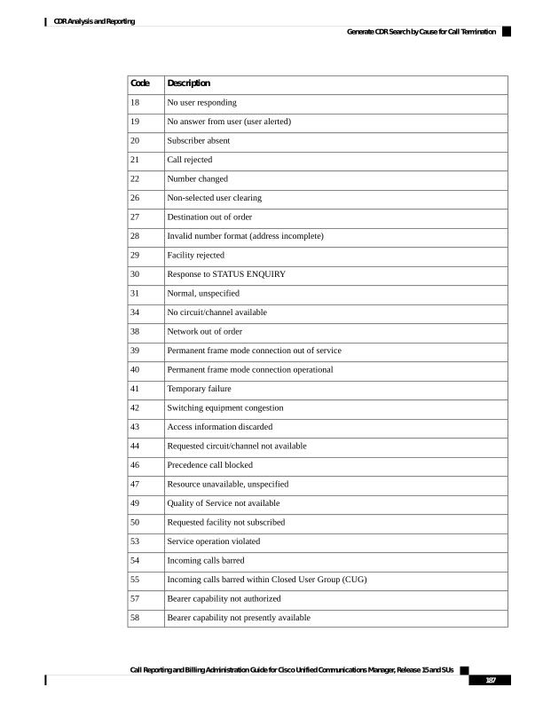
Page 200
Description
Code
Inconsistency in designated outgoing access information and subscriber class
62
Service or option not available, unspecified
63
Bearer capability not implemented
65
Channel type not implemented
66
Requested facility not implemented
69
Only restricted digital information bearer capability is available (national use)
70
Service or option not implemented, unspecified
79
Invalid call reference value
81
Identified channel does not exist
82
A suspended call exists, but this call identity does not
83
Call identity in use
84
No call suspended
85
Call having the requested call identity has been cleared
86
User not member of CUG (Closed User Group)
87
Incompatible destination
88
Destination number missing and DC not subscribed
90
Invalid transit network selection (national use)
91
Invalid message, unspecified
95
Mandatory information element is missing
96
Message type nonexistent or not implemented
97
Message is not compatible with the call state, or the message type is nonexistent or not
implemented
98
An information element or parameter does not exist or is not implemented
99
Invalid information element contents
100
The message is not compatible with the call state
101
Call terminated when timer expired; a recovery routine executed to recover from the error
102
Parameter nonexistent or not implemented - passed on (national use)
103
Message with unrecognized parameter discarded
110
Call Reporting and Billing Administration Guide for Cisco Unified Communications Manager, Release 15 and SUs
188
CDR Analysis and Reporting
Generate CDR Search by Cause for Call Termination
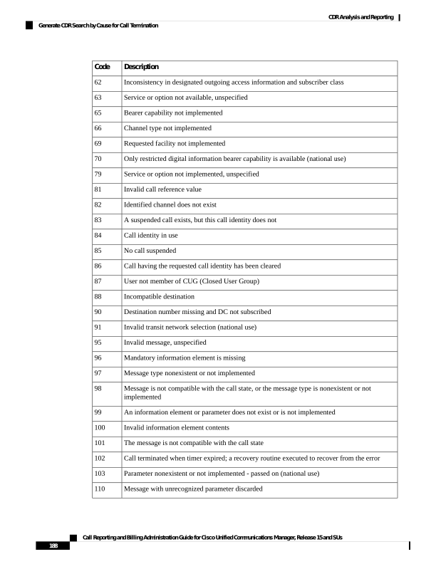
Page 201
Description
Code
Protocol error, unspecified
111
Precedence Level Exceeded
122
Device not Preemptable
123
Out of bandwidth (Cisco specific)
125
Call split (Cisco specific)
126
Interworking, unspecified
127
Precedence out of bandwidth
129
Table 82: Cisco-Specific Call Termination Cause Codes
Description
Hex Value Code
Decimal Value Code
Conference Full (was 124)
0x40000
262144
Call split (was 126) This code applies when a call
terminates during a transfer operation because it was
split off and terminated (was not part of the final
transferred call). This can help determine which calls
terminated as part of a feature operation.
0x60000
393216
Conference drop any party/Conference drop last party
(was 128)
0x70000
458752
CCM_SIP_400_BAD_REQUEST
0x1000029
16777257
CCM_SIP_401_UNAUTHORIZED
0x2000015
33554453
CCM_SIP_402_PAYMENT_REQUIRED
0x3000015
50331669
CCM_SIP_403_FORBIDDEN
0x4000015
67108885
CCM_SIP_404_NOT_FOUND
0x5000001
83886081
CCM_SIP_405_METHOD_NOT_ALLOWED
0x600003F
100663359
CCM_SIP_406_NOT_ACCEPTABLE
0x700004F
117440591
CCM_SIP_407_PROXY_AUTHENTICATION_REQUIRED
0x8000015
134217749
CCM_SIP_408_REQUEST_TIMEOUT
0x9000066
150995046
CCM_SIP__410_GONE
0xB000016
184549398
CCM_SIP_411_LENGTH_REQUIRED
0xC00007F
201326719
CCM_SIP_413_REQUEST_ENTITY_TOO_LONG
0xE00007F
234881151
CCM_SIP_414_REQUEST_URI_TOO_LONG
0xF00007F
251658367
Call Reporting and Billing Administration Guide for Cisco Unified Communications Manager, Release 15 and SUs
189
CDR Analysis and Reporting
Generate CDR Search by Cause for Call Termination
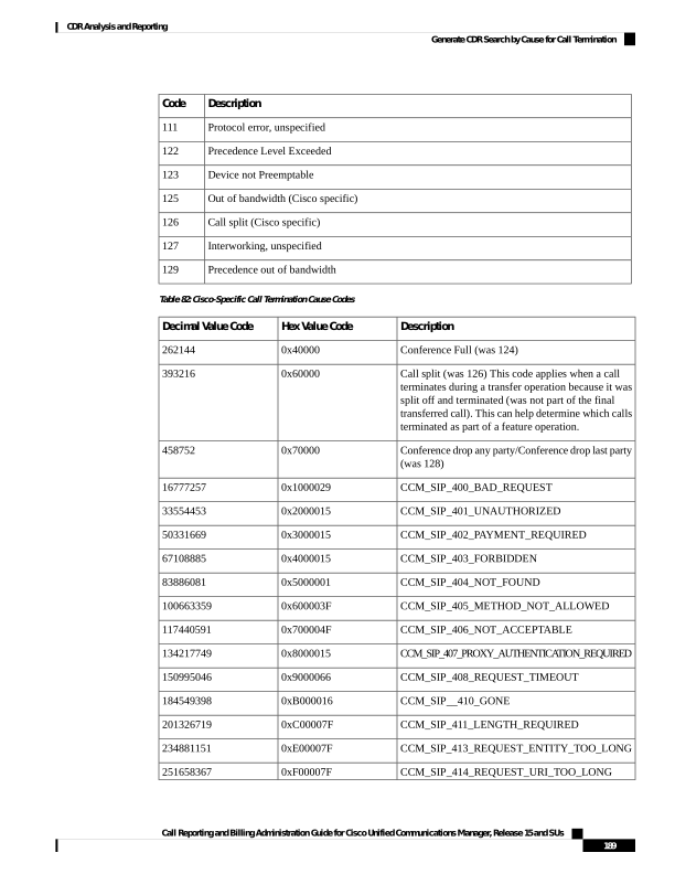
Page 202
Description
Hex Value Code
Decimal Value Code
CCM_SIP_415_UNSUPPORTED_MEDIA_TYPE
0x1000004F
268435535
CCM_SIP_416_UNSUPPORTED_URI_SCHEME
0x1100007F
285212799
CCM_SIP_420_BAD_EXTENSION
0x1500007F
83886207
CCM_SIP_421_EXTENSION_REQUIRED
0x1600007F
369098879
CCM_SIP_423_INTERVAL_TOO_BRIEF
0x1800007F
402653311
CCM_SIP_424_BAD_LOCATION_INFO
0x19000015
419430421
CCM_SIP_480_TEMPORARILY_UNAVAILABLE
0x40000012
1073741842
CCM_SIP_481_CALL_LEG_DOES_NOT_EXIST
0x41000029
1090519081
CCM_SIP_482_LOOP_DETECTED = 0x42000000
- EXCHANGE_ROUTING_ERROR
0x42000019
1107296281
CCM_SIP_483_TOO_MANY_HOOPS
0x43000019
1124073497
CCM_SIP_484_ADDRESS_INCOMPLETE
0x4400001C
1140850716
CCM_SIP_485_AMBIGUOUS
0x45000001
1157627905
CCM_SIP_486_BUSY_HERE
0x46000011
1174405137
CCM_SIP_487_REQUEST_TERMINATED
0x4700001F
1191182367
CCM_SIP_488_NOT_ACCEPTABLE_HERE
0x4800001F
1207959583
CCM_SIP_491_REQUEST_PENDING
0x4B000011
1258291217
CCM_SIP_493_UNDECIPHERABLE
0x4D000011
1291845649
CCM_SIP_500_SERVER_INTERNAL_ERROR
0x54000029
1409286185
CCM_SIP_502_BAD_GATEWAY
0x56000026
1442840614
CCM_SIP_503_SERVICE_UNAVAILABLE
0x57000029
1459617833
CCM_SIP_503_SERVICE_UNAVAILABLE_SER_OPTION_NOAVAIL
0xA700003F
-1493172161
CCM_SIP__504_SERVER_TIME_OUT
0x58000066
1476395110
CCM_SIP_505_SIP_VERSION_NOT_SUPPORTED
0x5900007F
1493172351
CCM_SIP_513_MESSAGE_TOO_LARGE
0x5A00007F
1509949567
CCM_SIP_600_BUSY_EVERYWHERE
0xA1000011
2701131793
CCM_SIP_603_DECLINE
0xA2000015
2717909013
CCM_SIP_604_DOES_NOT_EXIST_ANYWHERE
0xA3000001
2734686209
Call Reporting and Billing Administration Guide for Cisco Unified Communications Manager, Release 15 and SUs
190
CDR Analysis and Reporting
Generate CDR Search by Cause for Call Termination
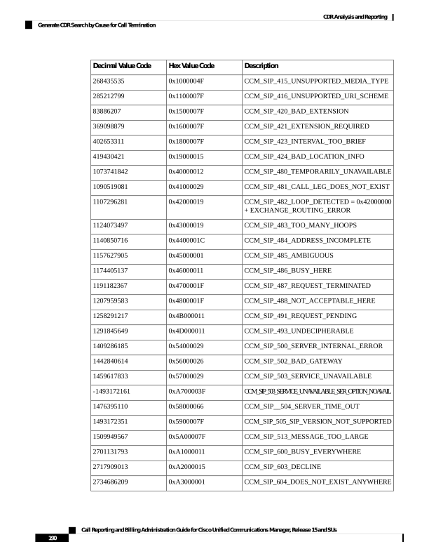
Page 203
Description
Hex Value Code
Decimal Value Code
CCM_SIP_606_NOT_ACCEPTABLE
0xA400001F
2751463455
This section describes how to search for information about the cause for termination of a call.
Procedure
Step 1
Choose CDR > Search > By Cause for Call Termination.
The Cause for Call Termination window displays.
Step 2
To search for the cause(s) of the termination of a call, highlight the cause(s) in the list of call termination
causes.
Tip
You can select more than one cause by clicking the causes that you want while holding down the Ctrl key on
your keyboard. You can also select all causes in the list by holding down the Shift key while clicking all
causes.
Step 3
With the desired cause(s) highlighted, click the down arrow above the Selected Call Termination Causes box.
The cause(s) that you selected displays in the Selected Call Termination Causes list box.
Note
To view a complete list of Call Termination Causes, see the “Call Termination Cause Codes” section in the
Cisco Unified Communications Manager Call Detail Records Administration Guide.
Step 4
Choose the date and time range of the period during which you want to search CDR data. When you configure
the time range, use UTC.
Step 5
Choose whether to run the CDR Search report with grouping or without grouping. If you chose with grouping,
check the box beside With Grouping. The default specifies Without Grouping.
Note
With Grouping choice means that the system returns CDR records that match the date and time range for the
search and groups them with their associated records. Without Grouping returns all the CDR records that
match the date and time range without grouping all the associated records for each call.
Step 6
Click OK.
The Call Termination Details window displays the report criteria for which the report was generated, along
with the total number of calls that were placed during the given time range as well as how many call legs and
the percentage of call legs for each cause code that is selected. The system displays only the oldest 100 records
that fall into the date and time ranges that you configured in Step 4, on page 191. If more than 100 records are
returned, the system truncates the results.
Step 7
To view CDRs, see the View Call Termination Details, on page 192.
Call Reporting and Billing Administration Guide for Cisco Unified Communications Manager, Release 15 and SUs
191
CDR Analysis and Reporting
Generate CDR Search by Cause for Call Termination
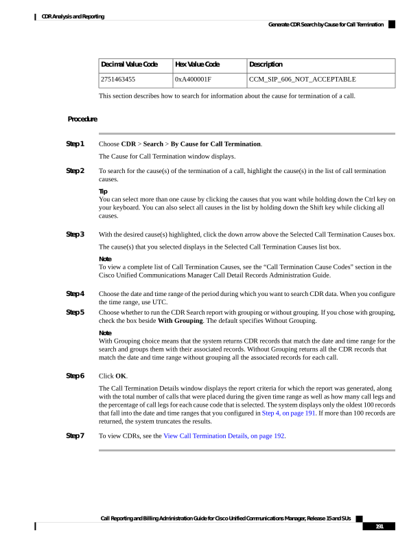
Page 204
View Call Termination Details
This section describes how to view the call termination details.
Before you begin
Follow the steps in the Generate CDR Search by Cause for Call Termination, on page 186 to display the Call
Termination Details window.
Procedure
Step 1
In the Select CDRs field, check the check box beside the individual CDRs that you want to view or if you
want to view all CDRs in the list, check the Select CDRs check box.
Step 2
After you have chosen the CDRs that you want to view, click View CDRs.
The CDR-CMR Search Results window displays.
To view the media information and the CDR-CMR dump records, click Others and View links.
Step 3
To print information that displays on the window, click Edit in your browser. Right-click Select All to
highlight the section of the report that you want to print. Click Print.
Step 4
To mail the report in an e-mail, click Send Report and follow the procedure that is described in the Mail
Reports, on page 63.
Generate CDR Search by Call Precedence
Only CAR administrators use the CDR Search by Call Precedence Levels feature.
This section describes how to search for calls according to call precedence.
Procedure
Step 1
Choose CDR > Search > By Call Precedence Level.
The CDR Search by Precedence Levels window displays.
Step 2
In Select Precedence Levels, check the check boxes for the call precedence levels on which you want to
search as described in the following table.
Table 83: Call Precedence Levels
Description
Voice Quality
Highest precedence setting for MLPP calls.
Flash Override
Second highest precedence setting for MLPP calls.
Flash
Third highest precedence setting for MLPP calls.
Immediate
Call Reporting and Billing Administration Guide for Cisco Unified Communications Manager, Release 15 and SUs
192
CDR Analysis and Reporting
View Call Termination Details
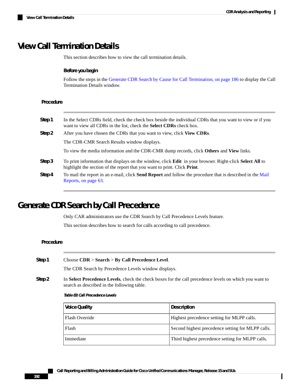
Page 205
Description
Voice Quality
Fourth highest precedence setting for MLPP calls.
Priority
Lowest precedence setting for MLPP calls.
Routine
Note
The Executive Override precedence level that is mentioned in the MLPP Precedence level on the Administration
page will be considered as Flash Override in this report.
Note
To check the check boxes of every precedence level, click Select All. To clear the check boxes, click Clear
All.
Step 3
In the From Date field, choose the date and time from which you want CDRs searched. The current time
displays in both Coordinated Universal Time (UTC) and local time and uses the following rules:
a)
The UTC and local time comprise a numeric string of mmddyyyy hhmmss, as in January 15, 2007 12:00:00.
b) The default FromDate and ToDate values display in UTC time.
c)
The default ToDate specifies the current time of the server in UTC time.
d) The default FromDate value specifies the ToDate value minus 1hour. For example, if ToDate = January
15, 2007 12:00:00, then the FromDate default value = January 15, 2007 11:00:00 (all times in UTC).
Step 4
In the To Date field, choose the date and time to which you want CDRs searched.
Step 5
Choose whether to run the CDR Search report With Grouping or Without Grouping. If you chose. With
Grouping, check the check box beside With Grouping. The default value specifies Without Grouping.
Note
With Grouping, choice means that the system returns CDR records that match the date and time range for the
search and groups them with their associated records. Without Grouping returns all the CDR records that
match the date and time range without grouping all the associated records for each call.
Step 6
Click OK.
The Call Precedence Details window displays and shows the call precedence levels and values, number of
call legs, and percentage of call legs.
Step 7
In the Select CDRs column, check the check boxes of the CDRs at which you want to look.
Step 8
Click View CDRs.
The CDR-CMR Search by Precedence Levels - CDR-CMR Search Results window displays. The system
displays only the oldest 100 records that fall into the date and time ranges that you configured in Step 3, on
page 193 and Step 3, on page 193Step 4, on page 193. If more than 100 records are returned, the system truncates
the results.
Step 9
To view the CMR data, click Others. To view both the CDR and CMR data fields, click View.
Step 10
To mail the report to e-mail recipient, click Send Report and follow the steps in the Mail Reports, on page
63.
Call Reporting and Billing Administration Guide for Cisco Unified Communications Manager, Release 15 and SUs
193
CDR Analysis and Reporting
Generate CDR Search by Call Precedence
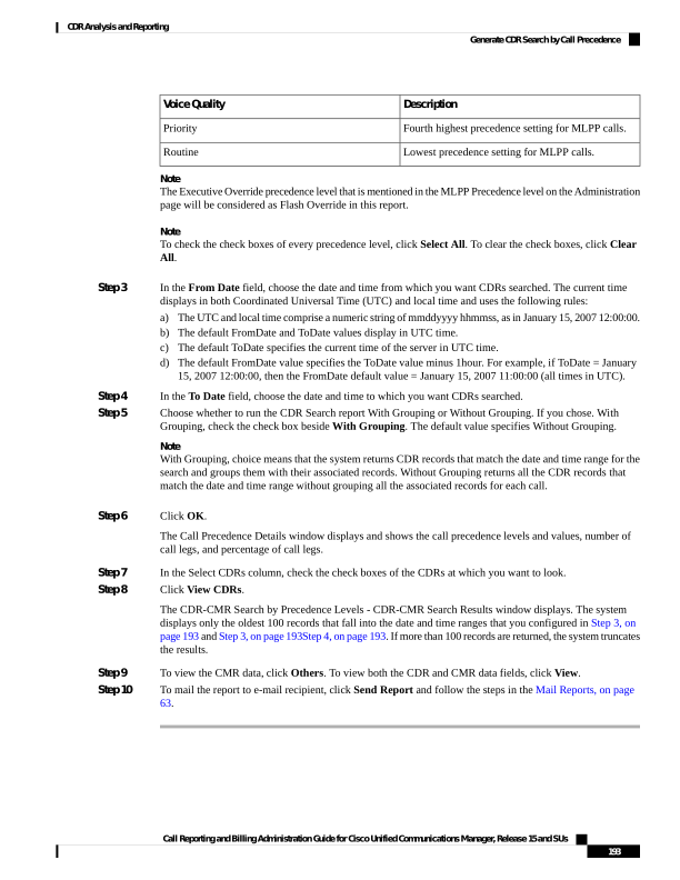
Page 206
Generate CDR Search for Malicious Calls
Only CAR administrators use the CDR Search for Malicious Calls feature.
This section describes how to search for malicious calls.
Procedure
Step 1
Choose CDR > Search > Malicious Calls.
The CDR Search for Malicious Calls window displays.
Step 2
Perform one of the following tasks:
a)
In the Select Phone Number/SIP URL(s) box, enter the phone number or SIP URL in the Phone Number/SIP
URL field and click Add Phone Number/SIP URL.
The phone number or SIP URL of the user displays in the Selected Phone Number/SIP URL(s) box.
b) To search for a user phone number or SIP URL, click the Search Internal Phone Number/SIP URL
based User link, enter the first few letters of the first and/or last name in the First Name and/or Last Name
fields, and click the Search button. When the results display, click the Select link next to the result that
you want to include. The phone number or SIP URL of the user displays in the Selected Phone Number/SIP
URLs box. Click Close.
Note
To remove the phone number or SIP URL, highlight the phone number or SIP URL that you want to
remove and click Remove Phone Number/SIP URL(s). To remove all phone numbers or SIP URL(s),
click Remove All Phone Number/SIP URL(s).
Step 3
Choose the date and time range of the period when you want to search for CDR data. The current time displays
in both Coordinated Universal Time (UTC) and local time and uses the following rules:
a)
The UTC and local time comprise a numeric string of mmddyyyy hhmmss, as in January 15, 2007 12:00:00.
b) The default FromDate and ToDate values display in UTC time.
c)
The default ToDate specifies the current time of the server in UTC time.
d) The default FromDate value specifies the ToDate value minus 1hour. For example, if ToDate = January
15, 2007 12:00:00, then the FromDate default value = January 15, 2007 11:00:00 (all times in UTC).
Step 4
Choose whether to run the CDR Search report With Grouping or Without Grouping. If you chose with grouping,
check the box beside With Grouping. The default value specifies Without Grouping
Note
With Grouping means that the system returns CDR records that match the date and time range for the search
and groups them with their associated records. Without Grouping returns all the CDR records that match the
date and time range without grouping all the associated records for each call together.
Step 5
Click OK.
The CDR-CMR Search Results window displays. The system only displays the oldest 100 records that fall
into the date and time ranges that you configured in Step 3, on page 194. If more than 100 records are returned,
the system truncates the results.
Step 6
To view the CMR data, click Others. To view both the CDR and CMR data fields, click View.
Call Reporting and Billing Administration Guide for Cisco Unified Communications Manager, Release 15 and SUs
194
CDR Analysis and Reporting
Generate CDR Search for Malicious Calls
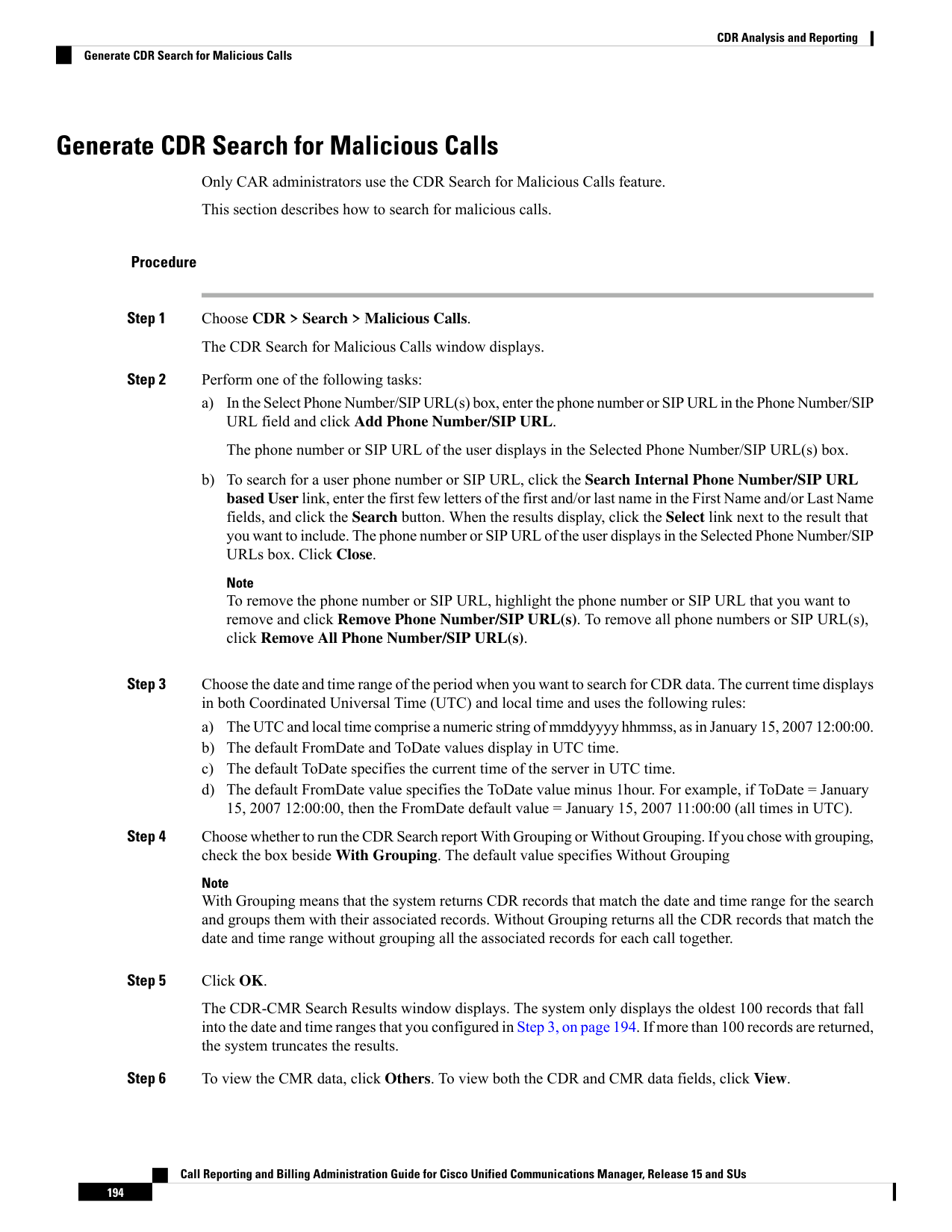
Page 207
Step 7
To mail the report to e-mail recipients, follow the steps in the Mail Reports, on page 63.
Generate CDR Search for Call Types
Only CAR administrators use the CDR Search for Different Call Types feature.
This section describes how to search for different call types.
Procedure
Step 1
Choose CDR > Search > By Call Types.
The CDR Search for Different Call Types window displays.
Note
You can enter a wildcard pattern like “!” or “X” to search on phone number or SIP URL. The “!” represents
any n digit that has 0-9 as each of its digits, and the “X” represents a single digit in the range 0-9.
Step 2
Choose the call type from the Select Call Type drop down list.
The following is a list of the call types:
• Successful IME Call: Calls that were successfully routed through IME trunks.
• Failed IME Calls: Calls that tried to route through the IME trunk, but failed.
• IME Calls with Fallback to Alternate Route: Calls which were initially routed through the IME trunk,
but due to some reason (for example, poor QoS), the fallback mechanism was initiated and these calls
were re-routed mid-call to an alternate route. The alternate route is typically a PSTN route.
• Successful Fallback Calls to Alternate Route: Calls which successfully fell back to the alternate route.
The alternate route is typically a PSTN route.
• Failed Fallback Calls to Alternate Route: Calls which failed to fall back to the alternate route.
• Calls on Alternate Route due to IME Redirection: Calls that tried to route (at call setup) to IME, but
for some reason were routed to an alternate route. The alternate route is typically a PSTN route.
Step 3
Perform one of the following tasks:
a)
To search CDRs based on phone numbers/SIP URLs, enter the phone number or SIP URL in the Phone
Number/SIP URL field and click Add Phone Number/SIP URL .
b) To search CDRs based on user, click the Search Internal Phone Number/SIP URL based User link,
enter the first few letters of the first and/or the last name in the First Name and/or Last Name fields, and
click Search. When the results display, click the Select link next to the result that you want to include.
Click Close.
The phone number or SIP URL displays in the Selected Phone Number/SIP URL(s) box.
Note
To delete an item from the Report Criteria box, click the Remove Phone Number/SIP URL(s) button.
You can delete all items from the Report Criteria box by clicking the Remove All Phone Number/SIP
URL(s) .
Call Reporting and Billing Administration Guide for Cisco Unified Communications Manager, Release 15 and SUs
195
CDR Analysis and Reporting
Generate CDR Search for Call Types
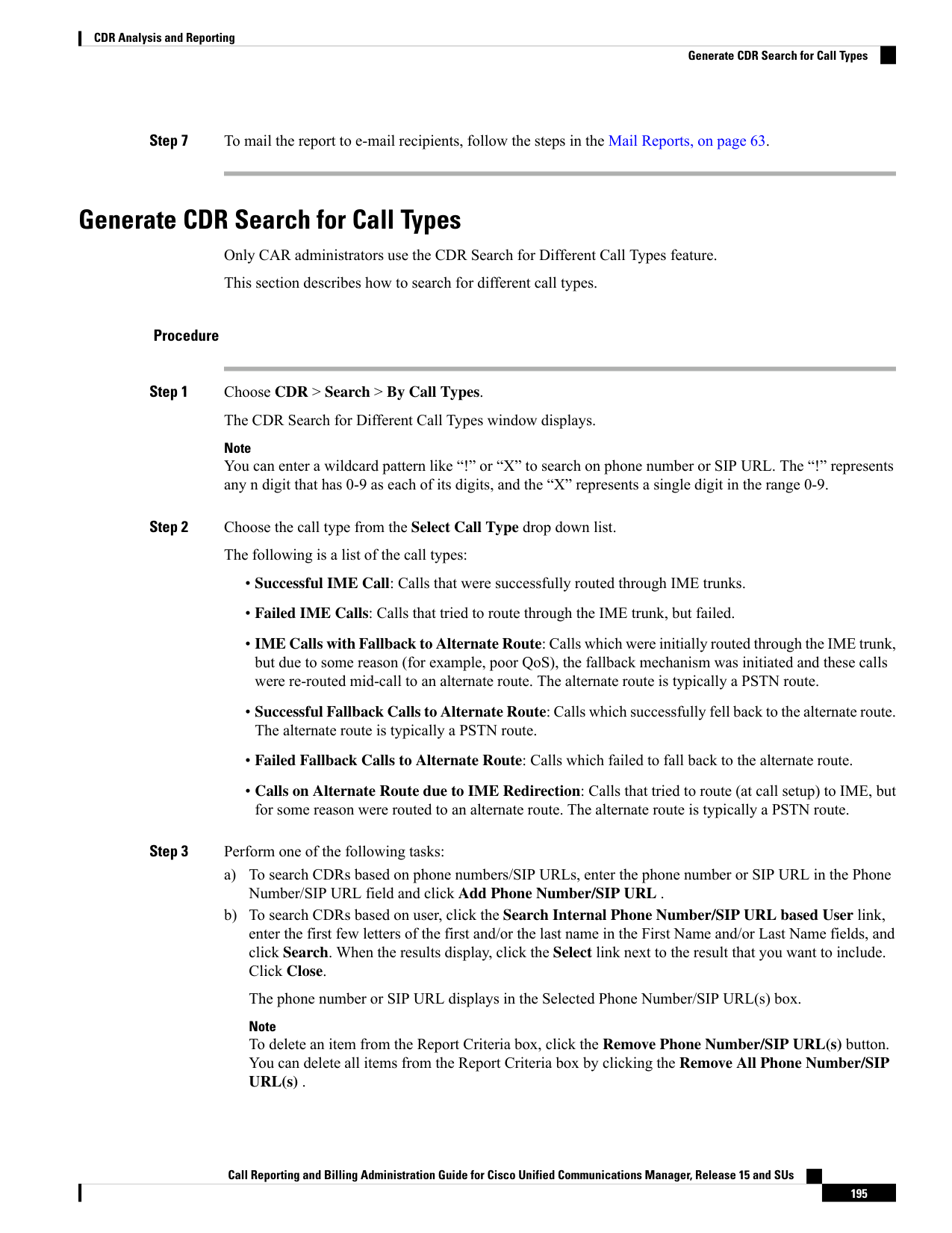
Page 208
Step 4
Current time displays in both Coordinated Universal Time (UTC) and local time. The UTC and local time
comprise a numeric string of mmddyyyy hhmmss, as in January 15, 2007 12:00:00.
Step 5
From the Select TimeZone field, choose the time zone that you want to use to search the CDRs. Options
include your local time zone and Greenwich Mean Time (GMT).
Step 6
In the From Date field and the To Date field, choose the date and time from and to which you want to search
the CDRs, respectively. The times in the From and To fields use the following rules:
a)
The default FromDate and ToDate values display in UTC time.
b) The default ToDate specifies the current time of the server in UTC time.
c)
The default FromDate value specifies the ToDate value minus 1hour. For example, if ToDate = January
15, 2007 12:00:00, then the FromDate default value = January 15, 2007 11:00:00 (all times in UTC).
Step 7
Click OK.
The CDR-CMR Search Results window displays. The system displays only the oldest 100 records that fall
into the date and time ranges that you configured in Step 3 and Step 4. If more than 100 records are returned,
the system truncates the results.
Step 8
To view the CMR data, click Others. To view both the CDR and CMR data fields, click View.
Step 9
To mail the report to e-mail recipient(s), click Send Report and follow the steps in the Mail Reports, on page
63.
CDR Search Results
The CDR search allows users to view the CDR/CMR fields as described in the table. The CDR search retrieves
the CDR/CMR files from the tbl_billing_data and tbl_billing_error tables of the CAR database.
See the following table.
Table 84: CDR Search Results
Description
Field
Specifies the serial or record number.
Sl No
Specifies the type of call: simple, transfer, forward,
pickup, conference, refer, replaces, or redirection.
Call Type
Specifies the call identifiers that are associated with
all the records for the entire call.
GCID_CMIdGCID_CallId
Specifies the server where the call
originator/destination was registered at the time of the
call.
Orig Node IdDest Node Id
Specifies the unique identifiers to the
originating/destination leg of a call.
Orig Leg IdDest Leg Id
Call Reporting and Billing Administration Guide for Cisco Unified Communications Manager, Release 15 and SUs
196
CDR Analysis and Reporting
CDR Search Results
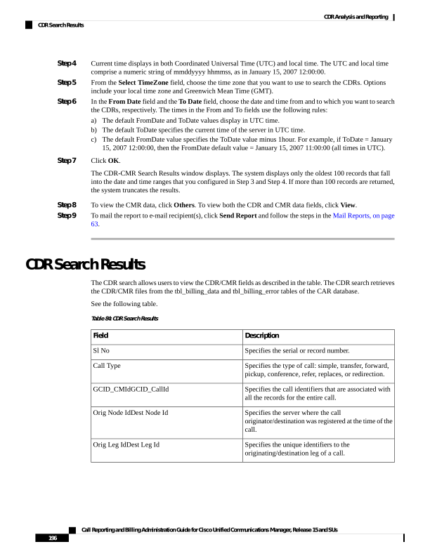
Page 209
Description
Field
The calling number specifies the directory number
where the call originated. The calling partition
specifies the partition that is associated with the
calling party.
Calling NoCalling No Partition
The called number specifies the directory number
from which the call was initially placed and is the
same as the Dest No when the call is not transferred
or forwarded. The called partition specifies the
partition that is associated with the called party.
Called NoCalled No Partition
The destination number specifies the directory number
where the call finally terminated and is the same as
the called number when the call is not transferred or
forwarded. The destination number partition specifies
the partition that is associated with the destination
number.
Dest NoDest No Partition
The last redirected number specifies the directory
number from which the call was finally redirected.
The last redirected number partition specifies the
partition that is associated with the last redirected
number.
Last Rd NoLast Rd No Partition
Specifies the packets that were received or lost for the
origination or destination leg of a call and a link to
the media information.
Media InfoOrig Pkts Rcd Dest Pkts Rcd Orig Pkts
Lost Dest Pkts Lost
Specifies a link to the CDR and CDR dump tables.
This link allows the users to view the values in the
CDR/CMR fields.
CDR - CMR Dump
Media Information
The media information table provides the following information. See the table.
Table 85: CDR Media Information
Description
Field
A unique identifier for the originating leg of a call.
Origination Leg
A unique identifier for the destination leg of a call.
Destination Leg
Call Reporting and Billing Administration Guide for Cisco Unified Communications Manager, Release 15 and SUs
197
CDR Analysis and Reporting
Media Information
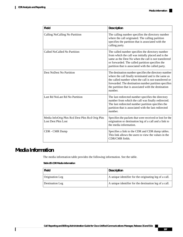
Page 210
Description
Field
The media parameters MediaTransportAdd_Ip,
PayLoadCapability, MediaCap_g723BitRate, Packets
Sent, Octets Sent, Packets Received, Octets Received,
Packets Lost, Jitter, Latency, QoS, VideoCap_Codec,
VideoCap_Bandwidth, VideoCap_Resolution,
VideoTransportAddress_IP, and
VideoTransportAddress_Port
Parameter
The value for all the preceding parameters for the
origination leg of the call.
Origination
The value for all the preceding parameters for the
destination leg of the call.
Destination
CDR and CMR Dump Tables
The CDR and CMR dump tables provide the following information. See the following table.
You can view the content of the voice quality metrics field, varVQMetrics, in the Origination CMR and
Destination CMR fields.
Note
Table 86: CDR and CMR Dump Tables
Description
Field
This field specifies the call detail record fields.
CDR
Only a single set of fields for origination and
destination exists. You can find the origination or
destination CMR by using the leg IDs. If the leg IDs
of the CMR match the Orig/Dest leg ID of the CDR,
the following record represents Orig/Dest CMR.
Origination CMR
Only a single set of fields for origination and
destination exists. You can find the origination or
destination CMR by using the leg IDs. If the leg IDs
of the CMR match the Orig/Dest leg ID of the CDR,
the following record represents Orig/Dest CMR.
Destination CMR
The following example displays output from a CDR dump file:
Sample CDR Dump File Output
cdrRecordType, globalCallID_callManagerId, globalCallID_callId, origLegCallIdentifier, dateTimeOrigination,
origNodeId, origSpan, origIpAddr, callingPartyNumber, callingPartyUnicodeLoginUserID, origCause_location,
origCause_value, origPrecedenceLevel, origMediaTransportAddress_IP, origMediaTransportAddress_Port,
origMediaCap_payloadCapability, origMediaCap_maxFramesPerPacket, origMediaCap_g723BitRate,
Call Reporting and Billing Administration Guide for Cisco Unified Communications Manager, Release 15 and SUs
198
CDR Analysis and Reporting
CDR and CMR Dump Tables

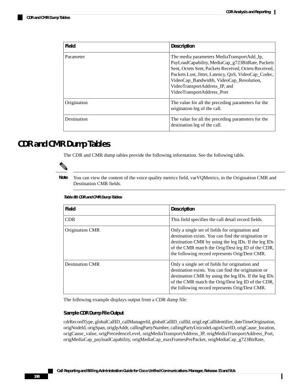
Page 211
origVideoCap_Codec, origVideoCap_Bandwidth, origVideoCap_Resolution, origVideoTransportAddress_IP,
origVideoTransportAddress_Port, origRSVPAudioStat, origRSVPVideoStat, destLegIdentifier, destNodeId,
destSpan, destIpAddr, originalCalledPartyNumber, finalCalledPartyNumber,
finalCalledPartyUnicodeLoginUserID, destCause_location, destCause_value, destPrecedenceLevel,
destMediaTransportAddress_IP, destMediaTransportAddress_Port, destMediaCap_payloadCapability,
destMediaCap_maxFramesPerPacket, destMediaCap_g723BitRate, destVideoCap_Codec,
destVideoCap_Bandwidth, destVideoCap_Resolution, destVideoTransportAddress_IP,
destVideoTransportAddress_Port, destRSVPAudioStat, destRSVPVideoStat, dateTimeConnect,
dateTimeDisconnect, lastRedirectDn, pkid, originalCalledPartyNumberPartition, callingPartyNumberPartition,
finalCalledPartyNumberPartition, lastRedirectDnPartition, duration, origDeviceName, destDeviceName,
origCallTerminationOnBehalfOf, destCallTerminationOnBehalfOf, origCalledPartyRedirectOnBehalfOf,
lastRedirectRedirectOnBehalfOf, origCalledPartyRedirectReason, lastRedirectRedirectReason,
destConversationId, globalCallId_ClusterID, joinOnBehalfOf, comment, authCodeDescription,
authorizationLevel, clientMatterCode, origDTMFMethod, destDTMFMethod, callSecuredStatus,
origConversationId, origMediaCap_Bandwidth, destMediaCap_Bandwidth, authorizationCodeValue,
outpulsedCallingPartyNumber, outpulsedCalledPartyNumber, origIpv4v6Addr, destIpv4v6Addr,
origVideoCap_Codec_Channel2, origVideoCap_Bandwidth_Channel2, origVideoCap_Resolution_Channel2,
origVideoTransportAddress_IP_Channel2, origVideoTransportAddress_Port_Channel2,
origVideoChannel_Role_Channel2, destVideoCap_Codec_Channel2, destVideoCap_Bandwidth_Channel2,
destVideoCap_Resolution_Channel2, destVideoTransportAddress_IP_Channel2,
destVideoTransportAddress_Port_Channel2, destVideoChannel_Role_Channel2, IncomingProtocolID,
IncomingProtocolCallRef, OutgoingProtocolID, OutgoingProtocolCallRef, currentRoutingReason,
origRoutingReason, lastRedirectingRoutingReason, huntPilotPartition, huntPilotDN
INTEGER, INTEGER, INTEGER, INTEGER, INTEGER, INTEGER, INTEGER, INTEGER, VARCHAR(50),
VARCHAR(128), INTEGER, INTEGER, INTEGER, INTEGER, INTEGER, INTEGER, INTEGER,
INTEGER, INTEGER, INTEGER, INTEGER, INTEGER, INTEGER, VARCHAR(64), VARCHAR(64),
INTEGER, INTEGER, INTEGER, INTEGER, VARCHAR(50), VARCHAR(50), VARCHAR(128), INTEGER,
INTEGER, INTEGER, INTEGER, INTEGER, INTEGER, INTEGER, INTEGER, INTEGER, INTEGER,
INTEGER, INTEGER, INTEGER, VARCHAR(64), VARCHAR(64), INTEGER, INTEGER, VARCHAR(50),
UNIQUEIDENTIFIER, VARCHAR(50), VARCHAR(50), VARCHAR(50), VARCHAR(50), INTEGER,
VARCHAR(129), VARCHAR(129), INTEGER, INTEGER, INTEGER, INTEGER, INTEGER, INTEGER,
INTEGER, VARCHAR(50), INTEGER, VARCHAR(2048), VARCHAR(50), INTEGER, VARCHAR(32),
INTEGER, INTEGER, INTEGER, INTEGER, INTEGER, INTEGER, VARCHAR(32), VARCHAR(50),
VARCHAR(50), VARCHAR(64), VARCHAR(64), INTEGER, INTEGER, INTEGER, INTEGER, INTEGER,
INTEGER, INTEGER, INTEGER, INTEGER, INTEGER, INTEGER, INTEGER, INTEGER, VARCHAR(32),
INTEGER, VARCHAR(32), INTEGER, INTEGER, INTEGER, VARCHAR(50), VARCHAR(50)
1, 1, 37, 29654625, 1258090294, 1, 0, 136269066, 1001, caruser2, 0, 16, 4, 136269066, 16790, 4, 20, 0, 0,
0, 0, 0, 0, 0, 0, 29654626, 1, 0, 85937418, 5555, 1002, caruser1, 0, 0, 4, 85937418, 30844, 4, 20, 0, 0, 0, 0,
0, 0, 0, 0, 1258090296, 1258090383, 5555, dcf0b5c9-7d57-475b-b166-d207a6617f34, , , , , 87,
SEP003094C3CCB0, SEP0002FD3BA528, 12, 0, 0, 0, 0, 0, 0, StandAloneCluster, 0, , , 0, , 3, 3, 0, 0, 64, 64,
, , , 10.77.31.8, 10.77.31.5,
101,0,5,0,0,1,100,0,3,0,0,1,3,0000000000000108012BB4AE00000002,3,0000000000000108012BB4B200000000,2,5,7,1000,
5555
Call Reporting and Billing Administration Guide for Cisco Unified Communications Manager, Release 15 and SUs
199
CDR Analysis and Reporting
CDR and CMR Dump Tables
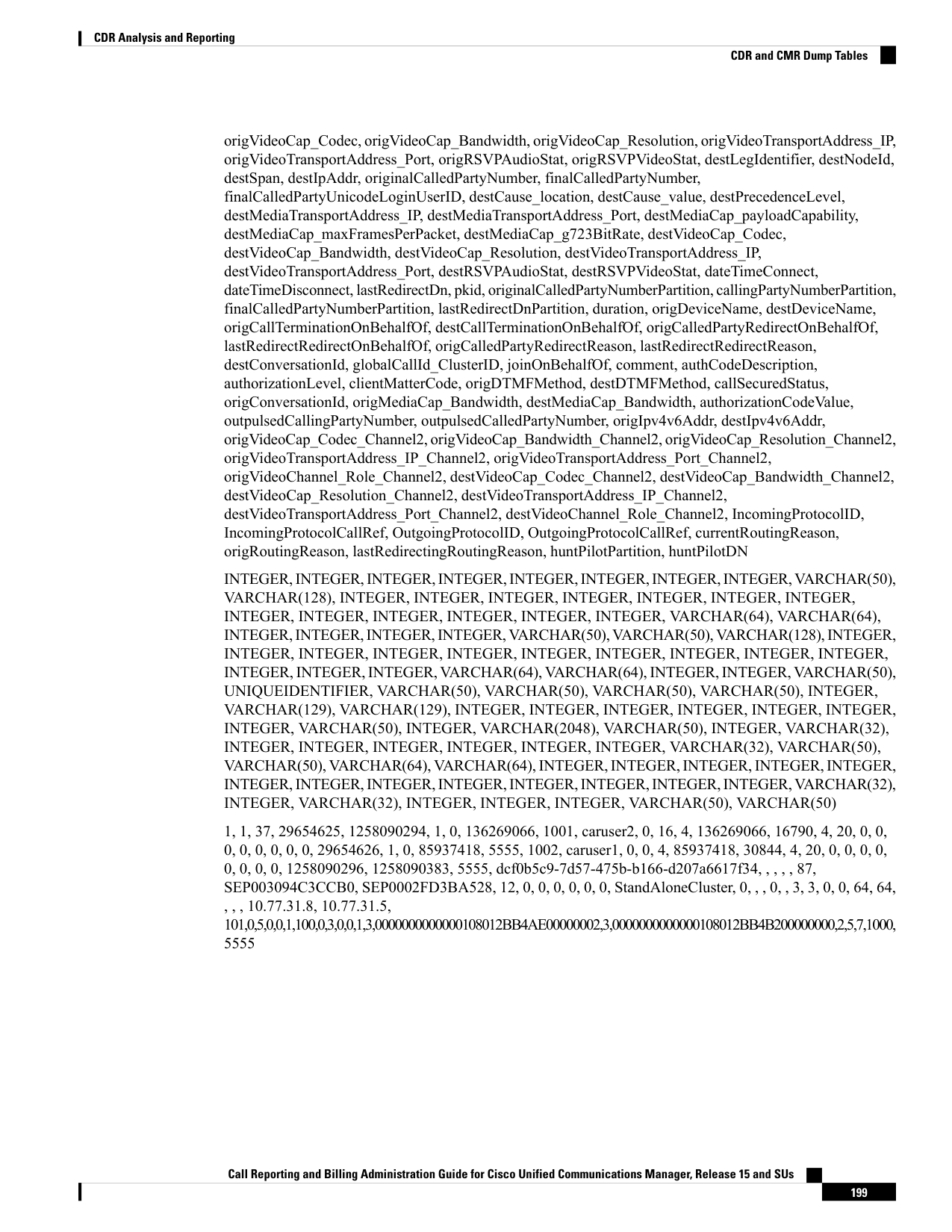
Page 212
Call Reporting and Billing Administration Guide for Cisco Unified Communications Manager, Release 15 and SUs
200
CDR Analysis and Reporting
CDR and CMR Dump Tables

Page 213
P A R T II
CDR Records
• Call Details Records Overview, on page 203
• CDR Field Descriptions, on page 213
• CDR Examples, on page 251

Page 214
Page 215
C H A P T E R 8
Call Details Records Overview
This chapter provides information about the format and logic of the Call Detail Records (CDRs) that the Cisco
Unified Communications Manager system generates. You can use this information for post-processing activities
such as generating billing records and network analysis.
When you install your system, the system enables CDRs by default, Call Management Records (CMRs)
remain disabled by default. You can enable or disable CDRs or CMRs at any time that the system is in
operation. You do not need to restart the Unified Communications Manager for the change to take effect. The
system responds to all changes within a few seconds. The system enables CMRs or diagnostic data separately
from CDR data.
• CDR Management, on page 203
• CDR Database Backup and Recovery, on page 205
• Record Processing, on page 205
• Call Information Record Types, on page 207
CDR Management
The CDR Management (CDRM) feature, a background application, supports the following capabilities:
• Collects the CDR/CMR files from the Unified Communications Manager server or node to the CDR
Repository server or node.
• Collects and maintains the CDR/CMR files on the server where you configure CAR.
• Maintains the CDR/CMR files on the CDR Repository node or CDR server.
• Allows third-party applications to retrieve CDR/CMR files on demand through a SOAP interface.
• Accepts on-demand requests for searching file names.
• Pushes CDR/CMR files from individual nodes within a cluster to the CDR Repository server or node.
• Sends CDR/CMR files to up to three customer billing servers via FTP/SFTP.
• Monitors disk usage of CDR/CMR files on the server where you configure CAR or on the CDR Repository
server or node.
• Periodically deletes CDR/CMR files that were successfully delivered. You can configure the amount of
storage that is used to store flat files. Predefined storage limits exist. If the storage limits are exceeded,
the CDR Repository Manager deletes old files to reduce the disk usage to the preconfigured low water
Call Reporting and Billing Administration Guide for Cisco Unified Communications Manager, Release 15 and SUs
203

Page 216
mark. The post-processing applications can later retrieve the buffered historical data to re-get any lost,
corrupted, or missing data. The CDRM feature, which is not aware of the flat file format, does not
manipulate the file contents.
The CDRM feature handles CDR files and CMR files in the same manner.
Note
CDRM comprises two default services, the CDR Agent and the CDR Repository Manager, and one activate
service, CDR onDemand Service.
CDR Agent
As part of the CDRM feature, a resident component on the server or node within a Unified Communications
Manager installation acts as the CDR Agent. On the server or nodes were both Unified Communications
Manager and the CDR Agent are running, Unified Communications Manager writes the CDRs into CDR flat
files in comma separated value (CSV) format. A special control character (“_”) that is prefixed to the filename
by the call processing module that indicates that the file is not available for transfer. If this control character
is not present, the system assumes that the file is available for transfer, and the CDR Agent then SFTPs those
files to the designated CDR repository node. Upon a successful transfer, the system deletes the local copy of
the file.
Reliability gets the highest priority for the CDRM feature. CDRs comprise important financial data, so the
goal of this feature is to guarantee that no CDR is lost. The Unified Communications Manager continuously
writes CDRs to flat files, closes existing flat files, and opens new ones. The number of records that are written
varies by the type of call and the significant changes that occur during a call: such as, ending the call,
transferring the call, redirecting the call, splitting the call, or joining the call.
On Linux platforms, the CDR Agent collects the CDR/CMR flat files that the Unified Communications
Manager generates and sends these files to the publisher through SFTP. The Windows versions of do not
support SFTP. On Windows platforms, the CDR Agent copies the files directly from the subscriber disk to
the shared publisher disk.
Note
CDR Repository Manager
Within a Unified Communications Manager server or cluster, one instance of the CDR Repository Manager
runs on the CDR Repository server or node. It manages CDR files that are received from the Unified
Communications Manager nodes and periodically sends the files to the specified customer/third-party billing
servers via FTP/SFTP.
When the file arrives on the CDR Repository server or node, the CDR Repository Manager detects it. The
system archives the file in a directory that is dedicated to the date that is indicated by the UTC timestamp that
was placed in the filename when the file was created.
If any external billing server is specified in the CDRM configuration, the system creates an empty file in each
of the corresponding folders for CAR and the billing servers, if CAR or the corresponding billing server is
activated. The CDR Agent monitors new CDR/CMR files that are generated on CallManager servers or nodes
by the call processing component. It sends the files to the CDR Repository node and then deletes the local
copy after the file is pushed out. The file sender component of the CDR Repository Manager detects these
Call Reporting and Billing Administration Guide for Cisco Unified Communications Manager, Release 15 and SUs
204
CDR Records
CDR Agent

Page 217
empty files and sends the file to the destination with the specified method. If the delivery is successful, the
system removes the empty file in the destination directory.
Every Unified Communications Manager can generate one CDR file and one CMR file every minute for up
to 1hour. You can configure the maximum disk space that is used for storage of CDR files in the CDR
Repository through provisioning.
The File Manager component of the CDR Repository Manager runs hourly. When the File Manager runs, it
deletes files with dates outside the configured preservation duration. It also checks whether the disk usage
has exceeded the high water mark. If so, the system deletes the processed CDR files until the low water mark
is reached, starting with the oldest files. However, if any CDR file to be deleted was not successfully sent to
the specified billing server, the system leaves it in the CDR Repository and raises a notification or alarm. The
system creates a flag file during the configured maintenance window, which denies access to the CDR files
for the CDR onDemand Service. The system removes the flag file after the maintenance window expires.
CDR onDemand Service
The CDR onDemand Service is a SOAP/HTTPS-based service, that runs on the CDR Repository server or
node. It receives SOAP requests for CDR filename lists based on a user-specified time interval (up to a
maximum of 1hour) and returns all lists that fit the duration that the request specifies.
The CDR onDemand Service can also handle requests for delivering a specific CDR file to a specified
destination through an SFTP API. All SFTP connections require a user id and password information for each
session setup. A separate SFTP session gets set up for every file that is sent, and the session is closed after
the file has been sent. The system can activate the CDR onDemand service on the CDR Repository node
because it has to access the CDR files in the repository. The system prohibits service during the maintenance
window. For more information on the CDR onDemand Service, see the Cisco Unified Communications
Manager Developers Guide.
For Cisco Unified Communications Manager Release 12.x and later releases, CDR onDemand Service is not
enabled by default. If you want to enable the CDR onDemand service, the service should be activated manually.
Execute the following command at the root level to activate the CDR onDemand service:
/usr/local/cm/bin/soapservicecontrol2.shCDRonDemandServiceCDRonDemanddeploy8443.
CDR Database Backup and Recovery
Be sure that the CAR and CDR Disaster Recovery Service (DRS) is integrated into the Cisco Unified
Communications Manager DRS.
For more information, see Administration Guide for Cisco Unified Communications Manager.
Record Processing
Unified Communications Manager generates two different types of call information records: CDRs and CMRs.
The CDR records store information about a call. The CMR records store information about the quality of the
streamed audio of the call. The CDR records relate to the CMR records by way of two GlobalCallID columns:
Global CallID callManagerId and GlobalCallID Called. Depending upon the call scenario, more than one
CMR may exist for each CDR.
When Unified Communications Manager places or receives a call, the system generates a CDR record when
the call terminates. The system writes the CDR to a flat file (text file). Inside the Unified Communications
Call Reporting and Billing Administration Guide for Cisco Unified Communications Manager, Release 15 and SUs
205
CDR Records
CDR onDemand Service
Page 218
Manager, the Call Control process generates CDR records. The system writes records when significant changes
occur to a given call, such as ending the call, transferring the call, redirecting the call, splitting the call, joining
a call, and so forth.
When CDR records are enabled, Call Control generates one or more CDR records for each call. The system
sends these records to EnvProcessCdr, where they are written to the flat files. The number of records that are
written varies by type of call and the call scenario. When Diagnostics are enabled, the device generates CMR
records for each call. The system writes one CMR record for each IP phone that is involved in the call or for
each Media Gateway Control Protocol (MGCP) gateway. The system also sends these records to EnvProcessCdr
where they get written to flat files.
The Unified Communications Manager generates CDR and CMR records but does not perform any post
processing on the records. The system writes the records to comma-delimited flat files and periodically passes
them to the CDR Repository. The CDR and CMR files represent a specific filename format within the flat
file.
Filename Format
The following example shows the full format of the filename:
tag_clusterId_nodeId_datetime_seqNumber
• tag—Identifies the type of file, either CDR or CMR.
• clusterId—Identifies the cluster or server where the Unified Communications Manager database
resides.
• nodeId—Identifies the node
• datetime—UTC time in yyyymmddhhmm format
• seqnumber—Sequence number
Two examples of the filenames follow:
cdr_Cluster1_01_200404021658_1
cmr_Cluster1_02_200404061011_6125
Flat File Format
The CDR and CMR flat files have the following format:
• Line 1—List of field names comma separated
• Line 2—List of field type comma separated
• Line 3—Data comma separated
• Line 4—Data comma separated
The following example shows a flat file:
Line1-“cdrRecordType”,“globalCallID_callManagerId”,“globalCallID_callId”,“origLegCallIdentifier”,...
Line2-INTEGER,INTEGER,INTEGER,INTEGER,...
Line3-1,1,388289,17586046,...
Line4-1,1,388293,17586054,...
Call Reporting and Billing Administration Guide for Cisco Unified Communications Manager, Release 15 and SUs
206
CDR Records
Record Processing
Page 219
If the value of the CDR Log Calls With Zero Duration Flag parameter is True, the system writes all calls to
a flat file. For more information, see Configuring CDR Service Parameters section in this book.
Note
Call Information Record Types
Unified Communications Manager generates two different types of call information records: Call Detail
Records (CDRs) and Call Management Records (CMRs), also called call diagnostic records. CDRs store
information about the endpoints of the call and other call control/routing aspects. CMRs contain diagnostic
information about the quality of the streamed audio of the call. More than one CMR can exist per CDR.
CMRs are supported by Cisco Unified IP Phones, Cisco 7960 series phones, and Media Gateway Control
Protocol (MGCP) gateways. If one of these endpoints is involved in a call, it will generate a CMR record after
the call terminates. Each endpoint in the call generates a separate CMR record. If the call involves endpoints
that do not support call diagnostics, no record gets generated for that endpoint. A call from a Cisco7960 phone
to an H.323 gateway generates one CMR record (from the Cisco 7960 phone).
CDRs relate to the CMRs via two globalCallID columns:
• globalCallID_callManagerId
• globalCallId_callId
When the Call Diagnostics service parameter is set to True, the system generates up to two CMRs for each
call. Each type of call, such as conference calls, call transfers, forwarded calls, and calls through gateways,
produce a set of records that get written to ASCII files at the end of the call. Only completed calls and failed
calls generate CDRs and CMRs. Unified Communications Manager does not perform any post-processing on
CDRs or CMRs.
Global Call Identifier
The Unified Communications Manager allocates a global call identifier (GlobalCallID_callId) each time that
a Cisco Unified IP Phones is taken off the hook or a call is received from a gateway. The GlobalCallID_callId
is allocated sequentially on a Unified Communications Manager server, independent of calls running on other
call servers in the cluster. Unified Communications Manager writes the GlobalCallID_callId value to a disk
file for every 1,000th call. When Unified Communications Manager restarts for any reason, it assigns the next
1000th number to the next GlobalCallID_callId.
For example, when a successful call gets made, the GlobalCallID_callId value in the CDR specifies 1001.
For the next call, the GlobalCallID_callId value specifies 1002, and so on. When Unified Communications
Manager restarts, the value for the next call in the CDR gets assigned 2001. The numbers continue sequentially
from there until Unified Communications Manager restarts again. For the next restart, the GlobalCallID_callId
value specifies 3001.
The maximum value that gets assigned to the GlobalCallID_callId is limited to 24 bits. When this limitation
occurs, the GlobalCallID_callId value gets reset to 1.
Note
Call Reporting and Billing Administration Guide for Cisco Unified Communications Manager, Release 15 and SUs
207
CDR Records
Call Information Record Types

Page 220
The GlobalCallID_callIds in the CDR file may not be in sequential order in the CDR flat file. If a call with
GlobalCallID_callId = 1 lasts longer than the call with GlobalCallID_callId = 2, then the CDR records for
GlobalCallId_callId= 2 are written before GlobalCallId_callId = 1. GlobalCallID_callIds may be completely
missing from the CDR flat file. If the first CDR record has GlobalCallID_callId = 1, and the second CDR has
GlobalCallID_callId = 3, that does not mean that the CDR for GlobalCallID_callId = 2 is missing.
GlobalCallID_callId = 2 did not meet the criteria to generate a CDR. The failure to generate a CDR can occur
because while the first and third call was successful, the second call was never completed; or,
GlobalCallID_callId = 2 could be part of a conference call. Each call leg in a conference call is assigned a
GlobalCallID_callId that is overwritten in the conference GlobalCallID_callId. The original GlobalCallID_callId
may not appear in the CDR flat file.
If the GlobalCallID_callId field is missing from the CDR record, CAR generates an error for that particular
record. For more information, see CDR Error Reports in this guide.
For Unified Communications Manager Release 5.x and later releases, the value in the GlobalCallId CDR field
survives over Unified Communications Manager restarts. In Release 4.x and earlier releases, although the
GlobalCallId field is time-based, the field gets reused under conditions of heavy traffic. Because of this
behavior, problems can occur with customer billing applications and the ability of CAR to correlate CMRs
with CDRs and to correlate conference call CDRs. For Release 5.x and later releases, GlobalCallId redesign
ensures that the field retains a unique value, at least for some days. Now, the last used globalCallId_callId
value gets written to disk periodically (for every x number of calls). The value gets retrieved after a Unified
Communications Manager restart, and the new globalCallId_callId value begins with this number plus x.
Note
Number Translations
The Unified Communications Manager can perform translations on the digits that a user dials. The translated
number, not the actual dialed digits, appears in the CDR.
For example, many companies translate “911” calls to “9-911,” so the caller does not need to dial an outside
line in an emergency. In these cases, the CDR contains “9911” although the user dials “911.”
Gateways can perform further modifications to the number before the digits are actually output through the
gateway. The CDR does not reflect these modifications.
Note
Partitions and Numbers
Within a CDR, a combination of extension number and partitions identifies each phone that is referenced, if
partitions are defined. When partitions exist, fully identifying a phone requires both values because extension
numbers may not be unique.
The Partition field stays empty when a call ingresses through a gateway. When a call egresses through a
gateway, the Partition field shows the partition to which the gateway belongs.
If the dial plan allows callers to use the # key for speed dialing, the # key goes into the database when it is
used. For example, the Called Party Number field may contain a value such as “902087569174#.”
The Party Number fields may include SIP URIs instead of the traditional calling/called party number.
Call Reporting and Billing Administration Guide for Cisco Unified Communications Manager, Release 15 and SUs
208
CDR Records
Number Translations

Page 221
CDRs use the Partition/Extension Numbers that are shown in the following table:
Table 87: Partition/Extension Numbers in CDRs
Description
Phone Number
This party placed the call. For transferred calls, the transferred
party becomes the calling party.
callingPartyNumber
This number designates the originally called party, after any digit
translations have occurred.
originalCalledPartyNumber
For forwarded calls, this number designates the last party to receive
the call.
For non-forwarded calls, this field shows the original called party.
finalCalledPartyNumber
For forwarded calls, this field designates the last party to redirect
the call.
For non-forwarded calls, this field shows the last party to redirect
(such as transfer and conference) the call.
lastRedirectDn
This number identifies the partition name that is associated with
the CallingPartyNumber field. This field uniquely identifies this
number because the Unified Communications Manager supports
multiple Cisco Unified IP Phones with the same extension number
in different partitions.
For calls that ingress through a gateway, this field remains blank.
callingPartyNumberPartition
This number identifies the partition name that is associated with
the OriginalCalledPartyNumber field. This field uniquely identifies
this number because the Unified Communications Manager
supports multiple Cisco Unified IP Phones with the same extension
number in different partitions.
For calls that egress through a gateway, this field specifies the
partition name that is associated with the route pattern that pointed
to the gateway.
originalCalledPartyNumberPartition
This number identifies the partition name that is associated with
the FinalCalledPartyNumber field. This field uniquely identifies
this number because the Unified Communications Manager
supports multiple Cisco Unified IP Phones with the same extension
number in different partitions.
For calls that egress through a gateway, this field specifies the
partition name that is associated with the route pattern that pointed
to the gateway.
finalCalledPartyNumberPartition
Call Reporting and Billing Administration Guide for Cisco Unified Communications Manager, Release 15 and SUs
209
CDR Records
Partitions and Numbers
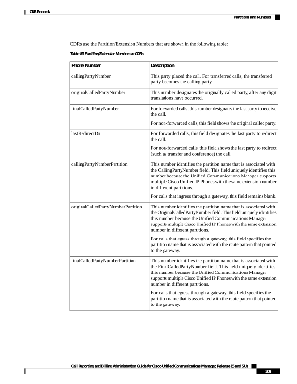
Page 222
Description
Phone Number
This number identifies the partition name that is associated with
the LastRedirectDn field. This field uniquely identifies this number
because the Unified Communications Managersupports multiple
Cisco Unified IP Phones with the same extension number in
different partitions.
For calls that egress through a gateway, this field specifies the
partition name that is associated with the route pattern that pointed
to the gateway.
lastRedirectDnPartition
The calling party number outpulsed from the device.
outpulsedCallingPartyNumber
The called party number outpulsed from the device.
outpulsedCalledPartyNumber
Timestamps
Timestamps within a CDR appear in Universal Coordinated Time (UTC). This value remains independent of
daylight saving time changes.
Unsigned 32-bit integers represent all time values. This unsigned integer value displays from the database as
a single integer. The field specifies a time_t value that is obtained from the operating system.
The following table displays the UTC timestamps that get included in the CDR.
Table 88: UTC Timestamps in CDRs
Description
Format
Field
For outgoing calls, this field designates the time that the device goes
off-hook.
For incoming calls, this field designates the time that the SETUP message
is received.
This field always gets populated.
UTC
dateTimeOrigination
This field designates the time that the devices connect.
Thisfield shows a zero if the call never connects.
UTC
dateTimeConnect
This field designates the time that the call disconnects. This field gets
set even if the call never connects. The time gets stored as UTC.
This field always gets populated.
UTC
dateTimeDisconnect
Call Clearing Causes
The CDR includes two call clearing cause codes: OrigCause and DestCause. When the originating party
releases the call, the OrigCause gets populated. When the terminating party releases the call, or the call is
rejected, the DestCause gets populated. When unpopulated, the cause code value shows zero.
Call Reporting and Billing Administration Guide for Cisco Unified Communications Manager, Release 15 and SUs
210
CDR Records
Timestamps
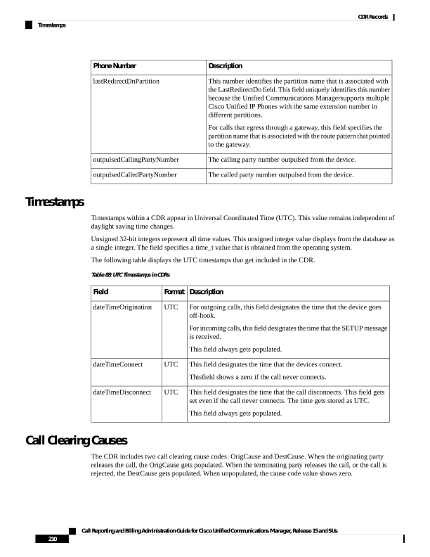
Page 223
Call Termination Cause Codes, on page 240 lists the call clearing cause code values per ITU specification
Q.850. For On Net call legs, the Unified Communications Manager determines the cause code value. For Off
Net call legs, the far-end switch determines the cause code value.
Convert Signed Decimal Value to IP Address
The system stores IP addresses as unsigned integers. The CDR file displays IP addresses as signed integers.
Toconvert the signed decimal value to an IP address, first convert the value to a hex number, taking into
consideration that it is really an unsigned number. The 32-bit hex value represents four bytes in reverse order
(Intel standard). To determine the IP address, reverse the order of the bytes and convert each byte to a decimal
number. The resulting four bytes represent the four-byte fields of the IP address in dotted decimal notation.
The file displays a negative number when the low byte of the IP address has the most significant bit set.
Note
For example, the IP address 192.168.18.188 displays as -1139627840. To convert this IP address, perform
the following procedure:
Procedure
Step 1
Convert the database display (-1139627840) to a hex value.
The hex value equals 0xBC12A8C0.
Step 2
Reverse the order of the hex bytes, as shown below:
CO A8 12 BC
Step 3
Convert the four bytes from hex to decimal, as shown below:
192 168 18 188
Step 4
The IP address displays in the dotted decimal format:
192.168.18.188
What to do next
When working with CDRs, you may want to read other tables in the CAR database to obtain information
about the type of device in each CDR because the correlation between devices in the device table and the IP
address that is listed in the CDR is not straightforward.
Call Reporting and Billing Administration Guide for Cisco Unified Communications Manager, Release 15 and SUs
211
CDR Records
Convert Signed Decimal Value to IP Address

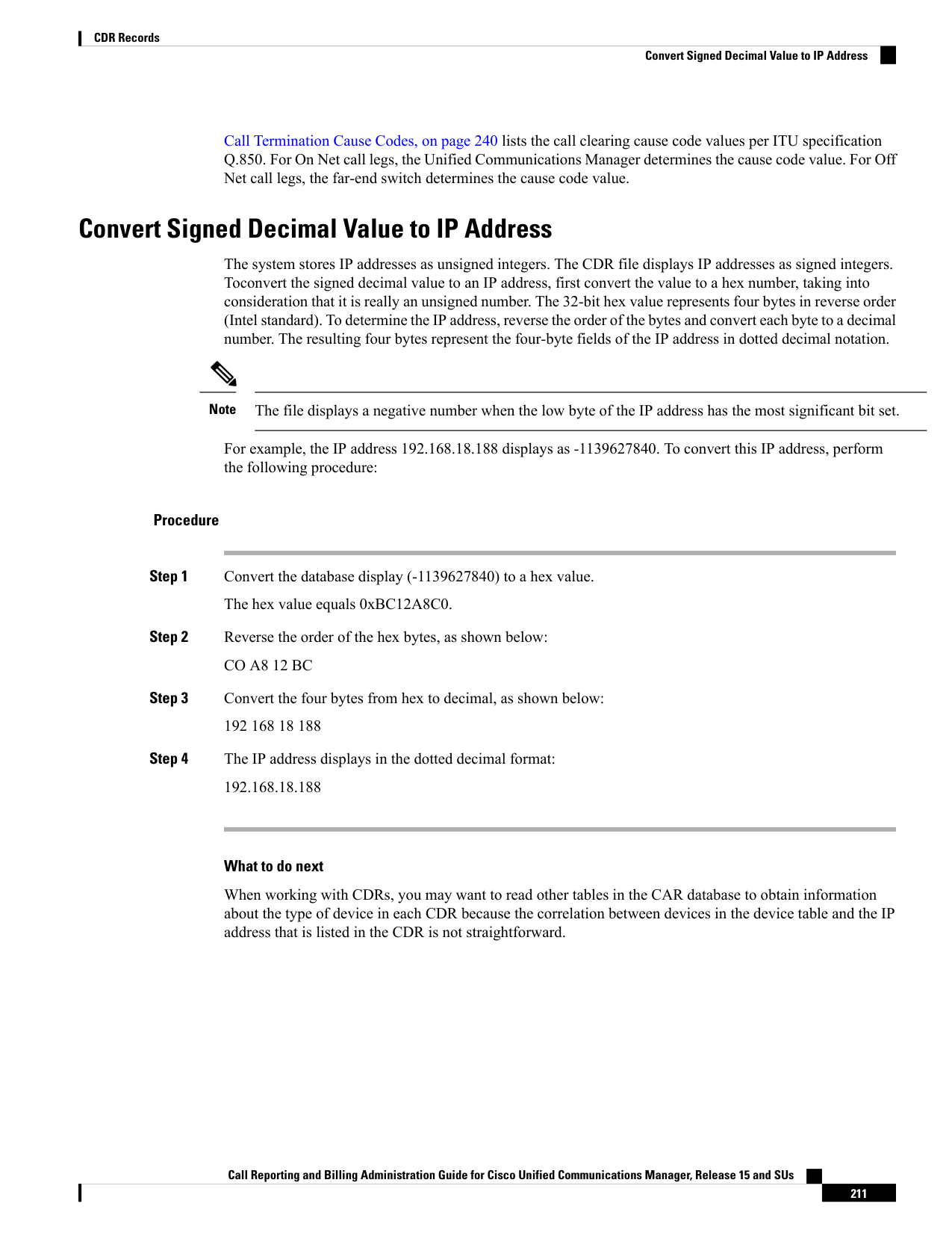
Page 224
Call Reporting and Billing Administration Guide for Cisco Unified Communications Manager, Release 15 and SUs
212
CDR Records
Convert Signed Decimal Value to IP Address

Page 225
C H A P T E R 9
CDR Field Descriptions
This chapter provides field descriptions for the Call Detail Records (CDRs) in the order in which they appear
in the CDR file.
• CDR Field Descriptions, on page 213
• Routing Reason Values for External Call Control, on page 236
• Cisco Call Detail Records Codes, on page 237
CDR Field Descriptions
The following table describes all fields in the current CDRs in the order in which they appear.
Table 89: CDR Field Descriptions
Description
Range of Values
Field Name
Defines the type of record. The following valid values apply:
• 0—Start call detail record (not used)
• 1—End call detail record (CDR)
• 2—CMR record
Default - For CDRs, this field always remains1.
0, 1, 2
cdrRecordType
Designates a unique Unified Communications Manager identity.
The Global Call ID comprises two fields: globalCallID_callId
globalCallID_callManagerId.
All records that are associated with a standard call have the same Global
Call ID in them.
Default - Ensure that this field is populated.
Positive Integer
globalCallID_callManagerId
Call Reporting and Billing Administration Guide for Cisco Unified Communications Manager, Release 15 and SUs
213

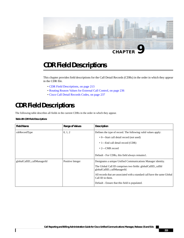
Page 226
Description
Range of Values
Field Name
Designates a unique call identity value that is assigned to each call. The
system allocates this identifier independently on each call server. Values
get chosen sequentially when a call begins. A value gets assigned for
each call, successful or unsuccessful. When Unified Communications
Manager restarts, it checks the file for the current globalCallID_callId
number and assigns the next 1000th number to the next
GlobalCallID_callId.
The Global Call ID consists of two fields: globalCallID_callId
globalCallID_callManagerId.
All records that are associated with a standard call have the same Global
Call ID in them.
Note
For Unified Communications Manager Release 5.x and later releases,
the value in the GlobalCallId CDR field survives over Unified
Communications Manager restarts. In Release 4.x and earlier releases,
although the GlobalCallId field is time-based, the field gets reused under
conditions of heavy traffic. Because of this behavior, problems can occur
with customer billing applications and the ability of CAR to correlate
CMRs with CDRs and to correlate conference call CDRs. For Release
5.x and later releases, GlobalCallId redesign ensures that the field retains
a unique value, at least for a certain number of days. Now, the last used
globalCallId_callId value gets written to disk periodically (for every x
number of calls). The value gets retrieved after a Unified
Communications Manager restart, and the new globalCallId_callId value
begins with this number plus x.
Default - Ensure that this field is populated.
Positive Integer
globalCallID_callId
Identifies the originating leg of a call. Be aware that this value is unique
within a cluster. If the leg of a call persists across several subcalls and
CDRs (as during a call transfer), this value remains constant.
Default - Ensure that this field is populated.
Positive Integer
origLegCallIdentifier
Identifies the date and time when the user goes off the hook or the date
and time that the H.323 SETUP message is received for an incoming
call. The time gets stored as UTC.
Default - Ensure that this field is populated.
Integer
dateTimeOrigination
Identifies the server, or node within a cluster, to which the originator of
the call is registered at the time that the call is made.
Default - Ensure that this field is populated.
Positive Integer
origNodeId
For calls that originate at a gateway, this field indicates the B-channel
number of the T1, PRI, or BRI trunk where the call originates, or a zero
value for FXS or FXO trunks.
For H.323 gateways, the span number remains unknown, and this field
contains the call leg ID of the originator.
For calls that did not originate at a gateway, the value specifies zero.
Default - This field gets populated based on these rules.
0, Positive Integer
origSpan
Call Reporting and Billing Administration Guide for Cisco Unified Communications Manager, Release 15 and SUs
214
CDR Records
CDR Field Descriptions
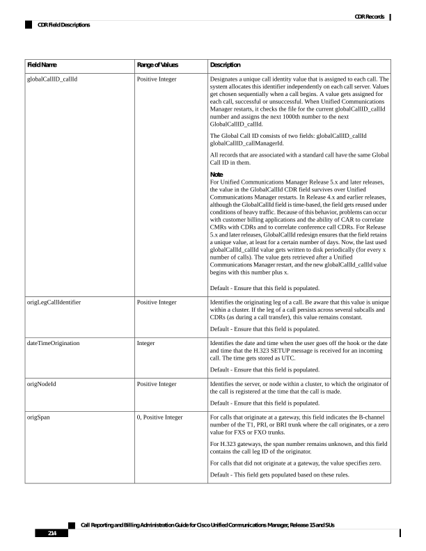
Page 227
Description
Range of Values
Field Name
Identifies the v4 IP address of the device that originates the call signaling.
For Cisco Unified IP Phones, this field specifies the v4 address of the
phone.
For PSTN calls, this field specifies the v4address of the H.323 gateway.
For intercluster calls, this field specifies the v4address of the remote
Unified Communications Manager.
Default - 0. If the v4 address does not exist for the originating device,
this field equals 0. This field gets populated based on these rules.
Integer
origIpAddr
Specifies a numeric string of up to 25 characters that indicates the calling
party number if the calling party is identified with a directory number.
If the calling party uses a blended address in the identity headers, this
field contains the directory number portion of the blended address.
For calls that originate at a Cisco Unified IP Phone, this field shows the
extension number of the line that is used.
For incoming H.323 calls, this field specifies the value that is received
in the Calling Party Number field in the Setup message. This field reflects
any translations that are applied to the Calling Party Number before it
arrives at the Unified Communications Manager (such as translations at
the gateway).
For the server calls, where Unified Communications Manager originates
a half call without a calling party, this field may remain empty.
CallingPartyNumber could contain a SIP URI.
Default - This field gets populated based on these rules.
Text String
callingPartyNumber
Specifies the calling party login user ID. The format of this field specifies
UTF_8.
Default - Empty string “”. If the user ID does not exist, this field stays
empty.
Unicode – UTF_8
callingPartyUnicodeLoginUserID
Specifies the Location field that is indicated in the ISDN release message
for clearing causes that are received over ISDN signaling links. See topics
that are related to call termination cause codes for a list of the valid values
per Q.850.
For clearing causes that are created internally by the Unified
Communications Manager, this value specifies zero.
Default - 0
0 to 15
For a list of cause code
values see Call Termination
Cause Codes, on page 240
origCause_location
Call Reporting and Billing Administration Guide for Cisco Unified Communications Manager, Release 15 and SUs
215
CDR Records
CDR Field Descriptions
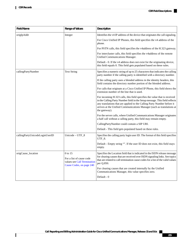
Page 228
Description
Range of Values
Field Name
Reflects the reason for clearance for the calls that are cleared by the
originating party.
Unified Communications Managercurrently uses the Q.850 codes and
some Unified Communications Managerdefined codes. See topics that
are related to call termination cause codes for a listing.
For calls that are cleared by the terminating party, this field specifies
zero.
In addition to the standard values that are described in Q.850, when a
call is split by a feature (transfer or conference), the CDR terminates,
and this field gets set to 393216. This represents a proprietary value for
this field.
Default - 0
0 to 129
For a list of cause code
values see Call Termination
Cause Codes, on page 240
origCause_value
Represents the precedence level of the original leg. For MLPP, each call
leg includes a precedence level.
• Precedence 0 = FLASH OVERRIDE/ EXECUTIVE OVERRIDE
• Precedence 1 = FLASH
• Precedence 2 = IMMEDIATE
• Precedence 3 = PRIORITY
• Precedence 4 = ROUTINE
Default - 4
0 to 4
origPrecedenceLevel
Identifies the v4 IP address of the device that originates the media for
the call.
For Cisco Unified IP Phones, this field specifies the v4 address of the
phone.
For PSTN calls, this field specifies the v4address of the H.323 gateway.
For intercluster calls, this field specifies the v4address of the remote
phone.
Default - 0. If media is not established or the address is not v4, this field
equals 0.
0, Integer
origMediaTransportAddress_IP
Identifies the IP port number that is associated with the
OrigMediaTransportAddress_IP field.
Default - 0. If media is not established, this field stays 0.
0, Positive Integer
origMediaTransportAddress_Port
Identifies the codec type that the originator uses to transmit media.
Unified Communications Manager currently uses the following payload
capability values: 0, 1-16, 18-20, 25, 32, 33, 81-86. See topics related to
codec types for a listing of the valid values.
Default - 0. If media is not established, this field stays 0.
0, Positive Integer
For a full list of codecs, see
Codec Types, on page 237
origMediaCap_payloadCapability
Call Reporting and Billing Administration Guide for Cisco Unified Communications Manager, Release 15 and SUs
216
CDR Records
CDR Field Descriptions
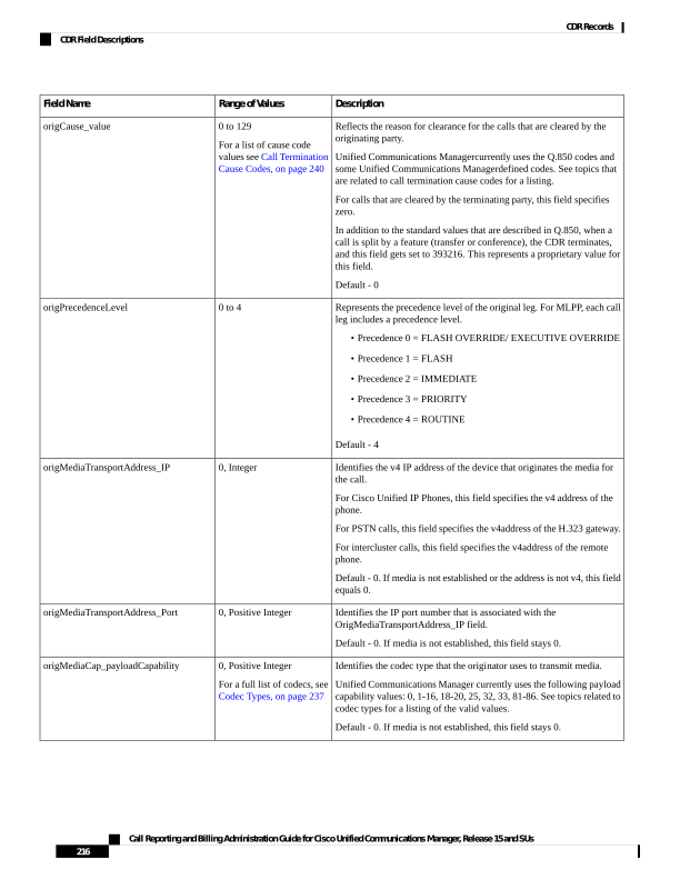
Page 229
Description
Range of Values
Field Name
Identifies the number of milliseconds of data per packet that the
originating party sends. This field normally gets set to 10, 20, or 30 for
G.729 or G.711 codecs, but the field can store any nonzero value.
Default - 0. If media is not established, this field stays 0.
0, Positive Integer
origMediaCap_maxFramesPerPacket
This field is not used in the current release of Unified Communications
Manager.
Default - This field will remain 0.
0
origMediaCap_g723BitRate
Identifies the codec type that the originator uses to transmit video (H.261,
H.263, or H.264.)
Default - 0. If media is not established, this field stays 0.
0,
100 = H.261,
101 = H.263,
103 = H.264
origVideoCap_Codec
Identifies the bandwidth that is measured in units of kbps.
Default - 0. If media is not established, this field stays 0.
0, Positive Integer
origVideoCap_Bandwidth
Indicates the transmitting resolution. In the case of H.264 codec or SIP
device, this field refers to the max transmitting resolution the device can
transmit for this call.
Default - 0. If media is not established, this field stays 0.
0,
1 = SQCIF,
2 = QCIF,
3 = CIF,
4 = CIF4,
5 = CIF16
6 = H263 custom resolution
7 = W360P
8 = VGA
9 = W448P
10 = HD720P
11 = HD1080P
12 = CIF2
origVideoCap_Resolution
Identifies the v4 IP address of the device that originates the call.
Default - 0. If media is not established or the address is not v4, this field
stays 0.
0, Integer
origVideoTransportAddress_IP
Identifies the video RTP port that is associated with the
origVideoTransportAddress_IP field.
Default - 0. If media is not established, this field stays 0.
0, Positive Integer
origVideoTransportAddress_Port
Call Reporting and Billing Administration Guide for Cisco Unified Communications Manager, Release 15 and SUs
217
CDR Records
CDR Field Descriptions
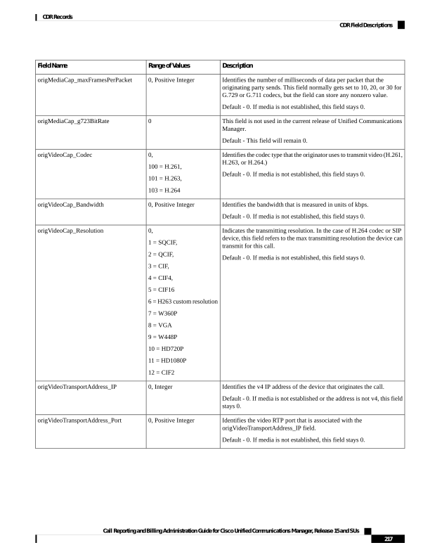
Page 230
Description
Range of Values
Field Name
Provides the status of the RSVP audio reservation from originator to
terminator.
0 – No reservation.
1 – RSVP Reservation Failure condition at call setup or feature
invocation.
2 – RSVP Reservation Success condition at the call setup or feature
invocation.
3 – RSVP Reservation No Response (RSVP Agent) condition at the call
setup or feature invocation.
4 – RSVP Mid Call Failure Preempted condition (preempted after the
call setup).
5 – RSVP Mid Call Failure Lost Bandwidth condition (includes all
mid-call failures except MLPP preemption).
Default – 0
0 to 5
origRSVPAudioStat
Provides the status of the RSVP video reservation from originator to
terminator.
0 – No reservation.
1 – RSVP Reservation Failure condition at call setup or feature
invocation.
2 – RSVP Reservation Success condition at call setup or feature
invocation.
3 – RSVP Reservation No Response (RSVP Agent) condition at call
setup or feature invocation.
4 – RSVP MID Call Failure Preempted condition (preempted after call
setup).
5 – RSVP MID Call Failure Lost Bandwidth condition (includes all
mid-call failures except MLPP preemption).
Default – 0
0 to 5
origRSVPVideoStat
Identifies the terminating leg of a call. This value remains unique within
a cluster. If the leg of a call persists across several sub-calls and,
consequently, several CDRs (as during a call transfer), this value remains
constant.
Default - 0. If the destination cannot be reached, this field stays 0.
0, Positive Integer
destLegIdentifier
Identifies the location, or node within a cluster, to which the terminating
party of the call is registered at the time that the call is made.
Default - 0. If the destination cannot be reached, this field stays 0.
0, Positive Integer
destNodeId
Call Reporting and Billing Administration Guide for Cisco Unified Communications Manager, Release 15 and SUs
218
CDR Records
CDR Field Descriptions
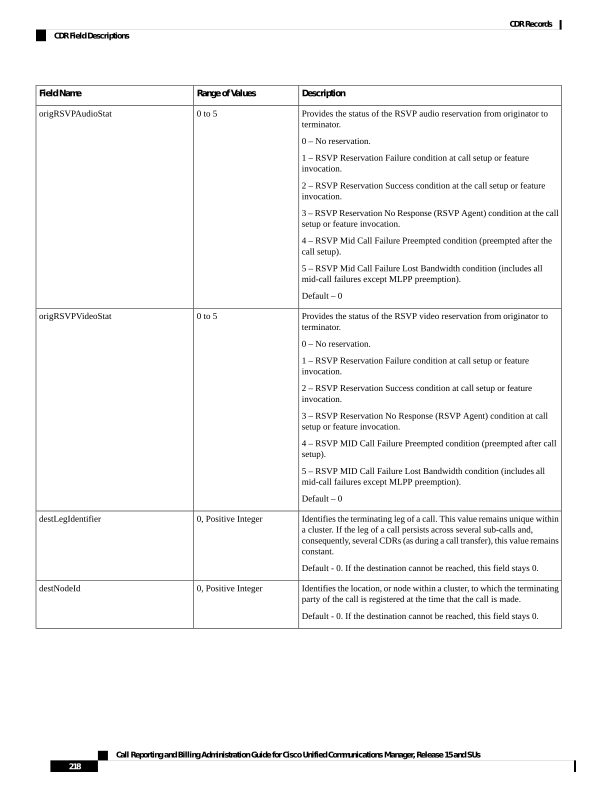
Page 231
Description
Range of Values
Field Name
For calls that are received at a gateway, this field indicates the B channel
number of the T1, PRI, or BRI trunk where the call is received, or a zero
value for FXS or FXO trunks.
For H.323 gateways, the span number remains unknown, and this field
contains the call leg ID of the destination.
For calls not terminating at a gateway, the value specifies zero.
Default - 0. If the destination cannot be reached, this field stays 0.
0, Positive integer
destSpan
Identifies the v4 IP address of the device that terminates the call signaling.
For Cisco Unified IP Phones, this field specifies the v4 address of the
phone.
For PSTN calls, this field specifies the v4address of the H.323 gateway.
For intercluster calls, this field specifies the v4address of the remote
Unified Communications Manager.
Default - 0. If the destination cannot be reached, this field stays 0. If the
v4 address does not exist for this device, the field equals 0.
0, Integer
destIpAddr
Specifies the number to which the original call was presented, prior to
any call forwarding. If translation rules are configured, this number
reflects the called number after the translations have been applied.
If a blended address is used for the called party, this field specifies the
directory number portion of the blended address.
This field represents a numeric string of up to 48 characters that can be
either digits or a SIP URL.
Default - Empty string “”. If destination cannot be reached, or if the called
party number is a directory URI, this field stays empty.
Text String
originalCalledPartyNumber
Specifies the phone number to which the call finally gets presented, until
it is answered or rings out. If no forwarding occurs, this number shows
the same number as the originalCalledPartyNumber.
If the call finally gets presented to a directory URI, the field remains
empty.
If a blended address is used, this field specifies the directory number
portion of the blended address.
For calls to a conference bridge, this field contains the actual identifier
of the conference bridge, which is an alphanumeric string (for example,
b0019901001).
This field represents an alphanumeric string that can be either digits or
a SIP URL.
Default - Empty string “”. If destination cannot be reached, this field
stays empty.
Text String
finalCalledPartyNumber
Specifies the login user ID. The format of this field specifies UTF_8.
Default - Empty string “”. If the user ID does not exist, this field stays
empty.
Unicode – UTF_8
finalCalledPartyUnicodeLoginUserID
Call Reporting and Billing Administration Guide for Cisco Unified Communications Manager, Release 15 and SUs
219
CDR Records
CDR Field Descriptions
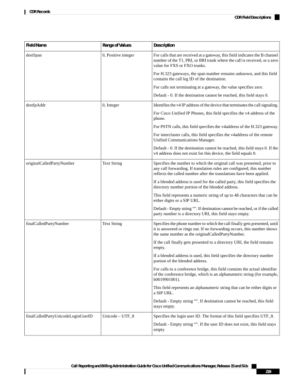
Page 232
Description
Range of Values
Field Name
For clearing causes that are received over ISDN signaling links, the ISDN
release message indicates this location field. See topics that are related
to call termination cause codes for a listing of the valid values per Q.850.
For clearing causes that Unified Communications Manager creates
internally, this value equals zero.
Default - 0. If the destination cannot be reached, this field stays 0.
0 to 15
For a list of cause code
values see Call Termination
Cause Codes, on page 240
destCause_location
Reflects the reason for the calss that the destination party cleared. See
topics that are related to call termination cause codes for a listing of the
valid values per Q.850.
For calls that the originating party clears, this field stays zero.
In addition to the standard values that are described in Q.850, when a
call gets split by a feature (transfer or conference), the CDR terminates,
and this field gets set to 393216. This represents a proprietary value for
this field.
Default - 0. If the destination cannot be reached, this field stays 0.
0 to 129
For a list of cause code
values see Call Termination
Cause Codes, on page 240
destCause_value
Represents the destination legs precedence level. For MLPP, each call
leg has a precedence level.
• Precedence 0 = FLASH OVERRIDE
• Precedence 1 = FLASH
• Precedence 2 = IMMEDIATE
• Precedence 3 = PRIORITY
• Precedence 4 = ROUTINE
Default - 4
0 to 4
destPrecedenceLevel
Identifies the v4 IP address of the device that terminates the media for
the call.
For Cisco Unified IP Phones, this field designates the v4 address of the
phone.
For PSTN calls, this field designates the v4address of the H.323 gateway.
For intercluster calls, this field shows the v4address of the remote phone.
Default - 0. If the destination cannot be reached or the IP address of the
destination is not v4, this field stays 0.
0, Integer
destMediaTransportAddress_IP
Identifies the IP port number that is associated with the
DestMediaTransportAddress_IP field.
Default - 0. If the destination cannot be reached, this field stays 0.
0, Positive Integer
destMediaTransportAddress_Port
Identifies the codec type that the terminating party uses to transmit media.
Unified Communications Manager currently uses the following payload
capability values: 0, 1-16, 18-20, 25, 32, 33, 81-86. See topics related to
codec types for a listing of the valid values.
Default - 0. If the destination cannot be reached, this field stays 0.
0, Positive Integer
For a full list of codecs, see
Codec Types, on page 237
destMediaCap_payloadCapability
Call Reporting and Billing Administration Guide for Cisco Unified Communications Manager, Release 15 and SUs
220
CDR Records
CDR Field Descriptions
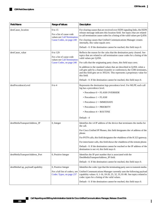
Page 233
Description
Range of Values
Field Name
Identifies the number of milliseconds of data per packet that the
terminating party of the call sends. This field normally gets set to 10, 20,
or 30 for G.729 or G.711 codecs but can store any nonzero value.
This field can specify zero if the media is never established.
Default - 0. If the destination cannot be reached, this field stays 0.
0, Positive Integer
destMediaCap_maxFramesPerPacket
This field is not used in the current release of Unified Communications
Manager.
Default - This field stays 0.
0
destMediaCap_g723BitRate
Identifies the codec type that the terminating party uses to transmit video
(H.261, H.263, or H.264).
Default - 0. If the destination cannot be reached, this field stays 0.
0,
100 = H.261,
101 = H.263,
103 = H.264
destVideoCap_Codec
Identifies the bandwidth, and is measured in units of kbps.
Default - 0. If the destination cannot be reached, this field stays 0.
0, Positive Integer
destVideoCap_Bandwidth
Indicates the transmitting resolution. In the case of H.264 codec or SIP
device, this field refers to the max transmitting resolution the device can
transmit for this call.
Default - 0. If media is not established, this field stays 0.
0,
1 = SQCIF,
2 = QCIF,
3 = CIF,
4 = CIF4,
5 = CIF16
6 = H263 custom resolution
7 = W360P
8 = VGA
9 = W448P
10 = HD720P
11 = HD1080P
12 = CIF2
destVideoCap_Resolution
Identifies the v4 IP address of the device that receives the call.
Default - 0. If the destination cannot be reached or the IP address of the
destination is not v4, this field stays 0.
0, Integer
destVideoTransportAddress _IP
Identifies the video RTP port that is associated with the
destVideoTransportAddress_IP field.
Default - 0. If the destination cannot be reached, this field stays 0.
0, Positive Integer
destVideoTransportAddress_Port
Call Reporting and Billing Administration Guide for Cisco Unified Communications Manager, Release 15 and SUs
221
CDR Records
CDR Field Descriptions
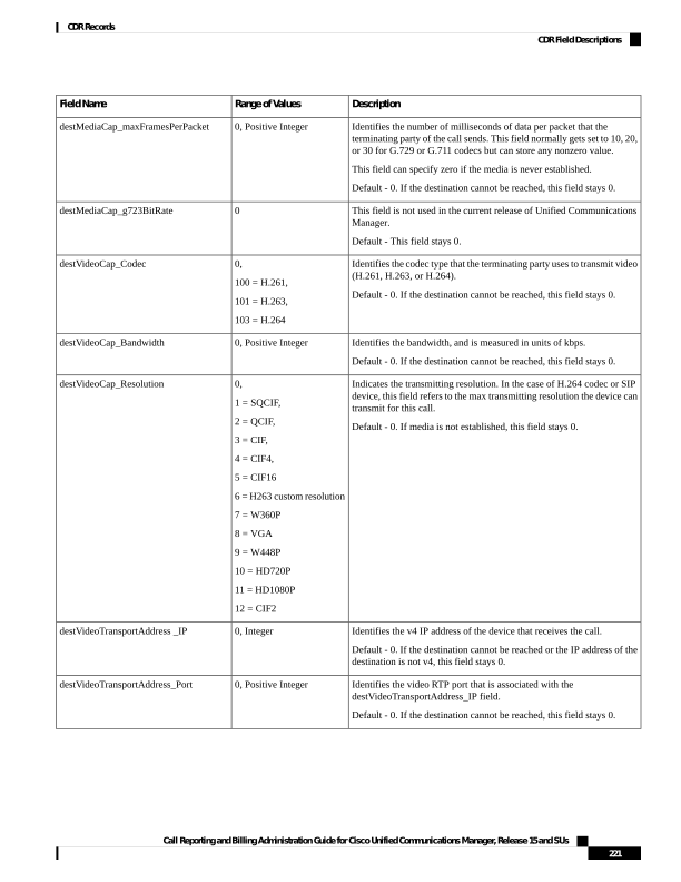
Page 234
Description
Range of Values
Field Name
Designates the status of the RSVP audio reservation from terminator to
originator.
0 – No reservation.
1 – RSVP Reservation Failure condition at the call setup or feature
invocation.
2 – RSVP Reservation Success condition at call setup or feature
invocation.
3 – RSVP Reservation No Response (RSVP Agent) condition at call
setup or feature invocation.
4 – RSVP Mid Call Failure Preempted condition (preempted after call
setup).
5 – RSVP Mid Call Failure Lost Bandwidth condition (includes all mid
call failures except MLPP preemption).
Default – 0
0 - 5
destRSVPAudioStat
Designates the status of the RSVP video reservation from terminator to
originator.
0 – No reservation.
1 – RSVP Reservation Failure condition at call setup or feature
invocation.
2 – RSVP Reservation Success condition at call setup or feature
invocation.
3 – RSVP Reservation No Response (RSVP Agent) condition at call
setup or feature invocation.
4 – RSVP Mid Call Failure Preempted condition (preempted after call
setup).
5 – RSVP Mid Call Failure Lost Bandwidth condition (includes all mid
call failures except MLPP preemption).
Default – 0
0 - 5
destRSVPVideoStat
Identifies the date and time that the call connects. The time gets stored
as UTC. If the call is never answered, this value shows zero.
Default - 0. If the call is never connected, this field stays 0.
0, Integer
dateTimeConnect
Identifies the date and time when the call is cleared. This field gets set
even if the call never connects. The time gets stored as UTC.
Default - Ensure that this field is populated.
Integer
dateTimeDisconnect
Call Reporting and Billing Administration Guide for Cisco Unified Communications Manager, Release 15 and SUs
222
CDR Records
CDR Field Descriptions
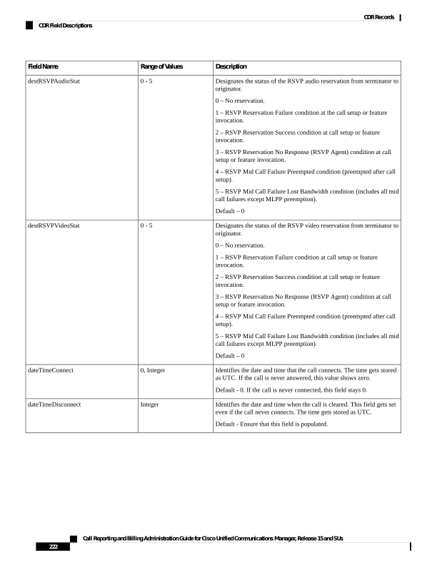
Page 235
Description
Range of Values
Field Name
Specifies a numeric string of up to 25 characters. The numeric string can
contain digits or a SIP URL.
For forwarded calls, this field specifies the phone number of the next to
last hop before the call reaches its final destination. If only one hop
occurs, this number matches the OriginalCalledPartyNumber.
If a blended address is used for call addressing, this field contains only
the directory number portion of the blended address.
For calls that are not forwarded, this field matches the
OriginalCalledPartyNumber and the FinalCalledPartyNumber.
For calls to a conference bridge, this field contains the actual identifier
of the conference bridge, which is an alphanumeric string (for example,
b0019901001).
Default - Empty string “”. If the call is never redirected, or if the next to
last hop address is a directory URI, this field remains empty.
Text String
lastRedirectDn
Identifies a text string that the database uses internally to uniquely identify
each row. This text string provides no meaning to the call itself.
Default - A unique ID should always populate this field.
Text String
pkid
Identifies unique partition name that is associated with the
OriginalCalledPartyNumber field because Unified Communications
Manager supports multiple Cisco Unified IP Phones with the same
extension number in different partitions.
For calls that egress through an H.323 gateway, this field uniquely
specifies the partition name that is associated with the route pattern that
points to the gateway.
Default - Empty string “”. If the original called party does not have a
partition, this field remains empty.
Text String
originalCalledPartyNumberPartition
Identifies unique partition name that is associated with the
CallingPartyNumber field because Unified Communications Manager
supports multiple Cisco Unified IP Phones with the same extension
number in different partitions.
For calls that ingress through an H.323 gateway, this field remains blank.
Default - Empty string “”. If the original called party does not have a
partition, this field remains empty.
Text String
callingPartyNumberPartition
Identifies unique partition name that is associated with the
FinalCalledPartyNumber field because Unified Communications Manager
supports multiple Cisco Unified IP Phones with the same extension
number in different partitions.
For calls that egress through an H.323 gateway, this field uniquely
specifies the partition name that is associated with the route pattern that
points to the gateway.
Default - Empty string “”. If the final called party does not have a
partition, this field remains empty.
Text String
finalCalledPartyNumberPartition
Call Reporting and Billing Administration Guide for Cisco Unified Communications Manager, Release 15 and SUs
223
CDR Records
CDR Field Descriptions
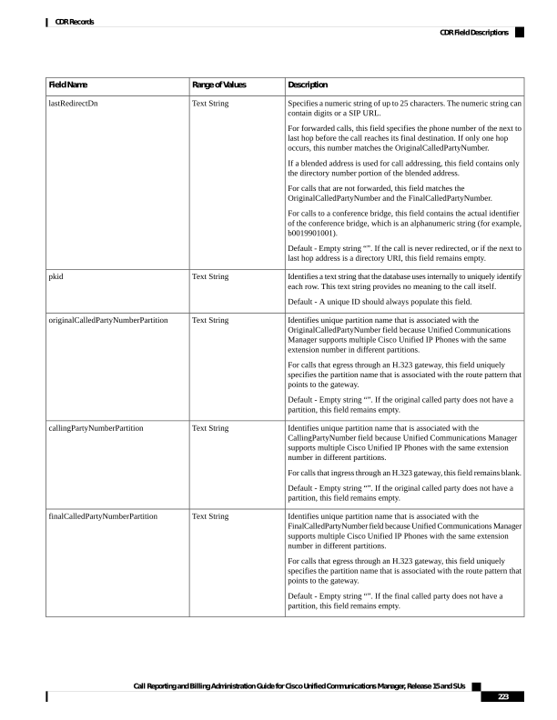
Page 236
Description
Range of Values
Field Name
Identifies unique partition name that is associated with the LastRedirectDn
field because Unified Communications Manager supports multiple Cisco
Unified IP Phones with the same extension number in different partitions.
For calls that egress through an H.323 gateway, this field specifies the
partition name that is associated with the route pattern that points to the
gateway.
Default - Empty string “”. If the last redirecting Party does not have a
partition or the call was never redirected, this field stays empty.
Text String
lastRedirectDnPartition
Identifies the difference between the Connect Time and Disconnect Time.
This field specifies the time that the call remains connected, in seconds.
This field remains zero if the call never connects or if it connects for less
than 1 second.
Default - 0
0, Positive integer
duration
Specifies the text string that identifies the name of the originating device.
Default - Ensure that this field is populated.
Text String
origDeviceName
Specifies the text string that identifies the name of the destination device.
Default - Empty string“”. If the original device does not have a name,
this field stays empty.
Text String
destDeviceName
Specifies code that identifies why the originator was terminated.
For example, if the originator of the call hangs up the phone, the
OnBehalfOf code shows “12” for Device. If the call terminates because
of a transfer, the OnBehalfOf code shows “10” for Transfer.
See topics related to CDR field descriptions for a list of the codes. This
release added new OnBehalfOf codes.
Default - 0
0, Positive Integer
For a complete list of
OnBehalfOf fields, see
OnBehalfof Codes, on page
249
origCallTerminationOnBehalfOf
Specifies code that identifies why the destination was terminated.
For example, if the destination of the call hangs up the phone, the
OnBehalfOf code shows “12” for Device. If the call terminates because
of a transfer, the OnBehalfOf code shows “10” for Transfer.
See topics related to CDR field descriptions for a list of the codes. This
release added new OnBehalfOf codes.
Default - 0
0, Positive Integer
For a complete list of
OnBehalfOf fields, see
OnBehalfof Codes, on page
249
destCallTerminationOnBehalfOf
Specifies code that identifies the reason for redirection of the original
called party.
For example, if the original called party was redirected because of a
conference, the OnBehalfOf code specifies “4.”
See topics related to CDR field descriptions for a list of the codes. This
release added new OnBehalfOf codes.
Default - 0
0, Positive Integer
For a complete list of
OnBehalfOf fields, see
OnBehalfof Codes, on page
249
origCalledPartyRedirectOnBehalfOf
Call Reporting and Billing Administration Guide for Cisco Unified Communications Manager, Release 15 and SUs
224
CDR Records
CDR Field Descriptions
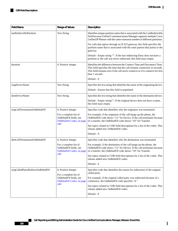
Page 237
Description
Range of Values
Field Name
Specifies code that identifies the reason for redirection of the last
redirected party.
For example, if the last redirected party was redirected on behalf of a
conference, the OnBehalfOf code specifies “4.”
See topics related to CDR field descriptions for a list of the codes. This
release added new OnBehalfOf codes.
Default - 0
0, Integer
For a complete list of
OnBehalfOf fields, see
OnBehalfof Codes, on page
249
lastRedirectRedirectOnBehalfOf
Identifies the reason for a redirect of the original called party.
See topics related to redirect reason codes for a complete list of the codes.
Default - 0
0, Integer
For a complete list of
OnBehalfOf fields, see
Redirect Reason Codes, on
page 246
origCalledPartyRedirectReason
Identifies the last redirect reason for redirection.
See topics related to redirect reason codes for a complete list of the codes.
Default - 0
0, Integer
For a complete list of
OnBehalfOf fields, see
Redirect Reason Codes, on
page 246
lastRedirectRedirectReason
Specifies a unique identifier that is used to identify the parties of a
conference call.
For conference chaining scenarios, the origConversationID and
destConversationID fields identify which conferences are chained
together.
Default - 0
0, Integer
destConversationID
Specifies a unique ID that identifies a cluster of Unified Communications
Managers.
The field is generated at installation and is not used by Unified
Communications Manager. The fields globalCallId_ClusterId +
globalCallId_CMId + globalCallId_CallId make up this unique key.
Default - This field should always be populated.
Text String
globalCallId_ClusterId
Specifies code that identifies the reason for a join.
For example, if the join takes place on behalf of a transfer, the
OnBehalfOf code specifies “10.”
See topics related to CDR field descriptions for a list of the codes.
Default - 0
0, Integer
For a complete list of
OnBehalfOf fields, see
OnBehalfof Codes, on page
249
joinOnBehalfOf
Allows features to add text to the CDRs. This text can describe details
about the call.
For example, the following field flags malicious calls:
Tag—CallFlag
Value—MALICIOUS
Default - Empty string “”.
Text String
comment
Call Reporting and Billing Administration Guide for Cisco Unified Communications Manager, Release 15 and SUs
225
CDR Records
CDR Field Descriptions
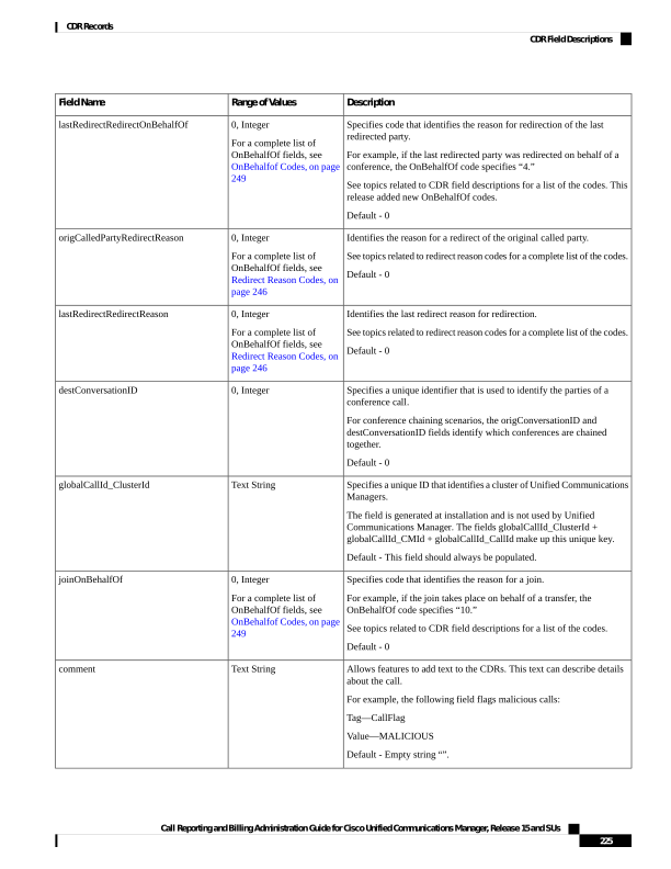
Page 238
Description
Range of Values
Field Name
Provides a description of the FAC.
Default - Empty string “” or null.
Text String
authCodeDescription
Displays the level of the FAC.
Default - 0
0, Integer
authorizationLevel
Displays the client matter code. Before the system extends a call, the
user enters a client matter code that can be used for assigning account or
billing codes to calls.
Default - Empty string “” or null.
Text String
clientMatterCode
Displays the DTMF method that the originator uses.
0 - No DTMF - Use ANY matched DTMF.
1 - OOB - Use OOB if endpoints behind SIPTrunk support it.
2 - 2833 - Use RFC2833 if endpoints behind SIPTrunk support it.
3 - OOB and 2833 - Use both KPML and RFC2833 if endpoints behind
SIPTrunk can support both.
4 - Unknown
Default - 0 (No preference)
0, Positive Integer
origDTMFMethod
Displays the DTMF method that the destination uses.
0 - No DTMF - Use ANY matched DTMF.1 - OOB - Use OOB if
endpoints behind SIPTrunk support it.2 - 2833 - Use RFC2833 if
endpoints behind SIPTrunk support it.3 - OOB and 2833 - Use both
KPML and RFC2833 if endpoints behind SIPTrunk can support both.4
- Unknown.
Default - 0 (No preference)
0, Positive Integer
destDTMFMethod
Displays the highest security status that is reached during a call. For
example, if the call is originally unsecured, and later the call changes to
secured, the CDR contains 1 for “Secured” even though different portions
of the call have different status values.
0 - Non-secured
1 - Authenticated (not encrypted)
2 - Secured (encrypted)
Default - 0 (Non-secured)
0, Positive Integer
callSecuredStatus
Identifies the conference ID that is associated with the originating leg of
the call. In most cases, this field equals 0.
For conference chaining scenarios, the origConversationID and
destConversationID fields identify which conferences are chained
together.
Default - 0
Integer
origConversationID
Displays the media bandwidth that is used at the origination of the call.
Default - 0
0, Positive Integer
origMediaCap_Bandwidth
Call Reporting and Billing Administration Guide for Cisco Unified Communications Manager, Release 15 and SUs
226
CDR Records
CDR Field Descriptions
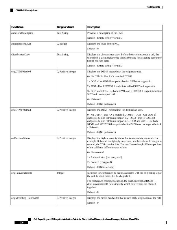
Page 239
Description
Range of Values
Field Name
Displays the media bandwidth that is used at the destination of the call.
Default - 0
0, Positive Integer
destMediaCap_Bandwidth
Displays the Forced Authorization Code (FAC) that is associated with
the call.
Default - Empty string “” or null.
Text String
authorizationCodeValue
Comprises an alphanumeric string of up to 50 characters.
The calling party number gets outpulsed from the device. This field gets
populated only when normalization or localization takes place at the
device.
Default - Empty string “” or null.
Text String
outpulsedCallingPartyNumber
Comprises an alphanumeric string of up to 50 characters.
The called party number gets outpulsed from the device. This field gets
populated only when normalization or localization takes place at the
device.
Default - Empty string “”or null.
Text String
outpulsedCalledPartyNumber
Comprises an alphanumeric string of up to 64 characters.
This field identifies the IP address of the device that originates the call
signalling. The field can be either IPv4 or IPv6 format depending on the
type of IP address that gets used for the call.
For Cisco Unified IP Phones, this field is the address of the Cisco Unified
IP Phone. For PSTN calls, this field is the address of the gateway. For
intercluster calls, this field is the address of the remote Unified
Communications Manager.
The IP addressis either in dotted decimal format or in colon separated
hexadecimal format.
Default - TheIP address of the originating device as reported by the device
or used for the call after media negotiation.
Text string
origIpv4v6Addr
Comprises an alphanumeric string of up to 64 characters.
This field identifies the IP address of the device that terminates the call
signalling. The field can be either in IPv4 or IPv6 format depending upon
the type of IP address that gets used for the call.
For Cisco Unified IP Phones, this field is the address of the Cisco Unified
IP Phone. For PSTN calls, this field is the address of the gateway. For
intercluster calls, this field is the address of the remote Unified
Communications Manager.
The IP addressis either in dotted decimal format or in colon separated
hexadecimal format.
Default - Empty String “” or null. If the destination does not get reached,
this field stays empty.
Text string
destIpv4v6Addr
Call Reporting and Billing Administration Guide for Cisco Unified Communications Manager, Release 15 and SUs
227
CDR Records
CDR Field Descriptions
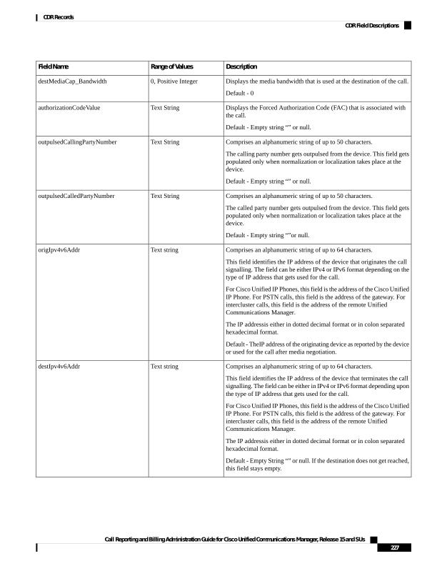
Page 240
Description
Range of Values
Field Name
Identifies the codec type that the originator uses to transmit video (H.261,
H.263, or H.264) for the second video channel.
Default - 0. If media does not get established, this field displays 0. Also,
if H.239 and BFCP are not supported for this call, this field displays 0.
0,
100 = H.261,
101 = H.263,
103 = H.264,
origVideoCap_Codec_Channel2
Identifies the bandwidth measured in units of kbps for the second video
channel.
Default - 0. If media does not get established, this field displays 0. Also,
if H.239 and BFCP are not supported for this call, this field displays 0.
0, Positive integer
origVideoCap_Bandwidth_Channel2
Indicates the transmitting resolution for the second video channel. In the
case of H.264 codec or SIP device, this field refers to the maximum
transmitting resolution the device can transmit for this call.
Default - 0. If media is not established, this field stays 0. Also, if H.239
and BFCP are not supported for this call, this field displays 0.
0,
1 = SQCIF,
2 = QCIF,
3 = CIF,
4 = CIF4,
5 = CIF16
6 = H263 custom resolution
7 = W360P
8 = VGA
9 = W448P
10 = HD720P
11 = HD1080P
12 = CIF2
origVideoCap_Resolution_Channel2
Identifies the v4 IP address of the device that originates the call for the
second video channel.
Default - 0. If media does not get established, this field displays 0. Also,
if H.239 and BFCP are not supported for this call, this field displays 0.
0, Integer
origVideoTransportAddress_IP_Channel2
Identifies the video RTP port associated with the
origH239VideoTransportAddress_IP field for the second video channel.
Default - 0. If media does not get established, this field displays 0. Also,
if H.239 and BFCP are not supported for this call, this field displays 0.
0, Positive integer
origVideoTransportAddress_Port_Channel2
Identifies the H.239 video channel role of the device that originates.
Default - 0. If media does not get established, this field displays 0. Also,
if H.239 is not supported, this field displays 0.
0 = Presentation role,
1 = Live role,
Positive integer
origVideoChannel_Role_Channel2
Identifies the codec type that the terminating party uses to transmit video
(H.261, H.263, or H.264) for the second video channel.
Default - 0. If the destination cannot be reached, this field stays 0. Also,
if H.239 and BFCP are not supported for this call, this field displays 0.
0,
100 = H.261,
101 = H.263,
103 = H.264
destVideoCap_Codec_Channel2
Call Reporting and Billing Administration Guide for Cisco Unified Communications Manager, Release 15 and SUs
228
CDR Records
CDR Field Descriptions
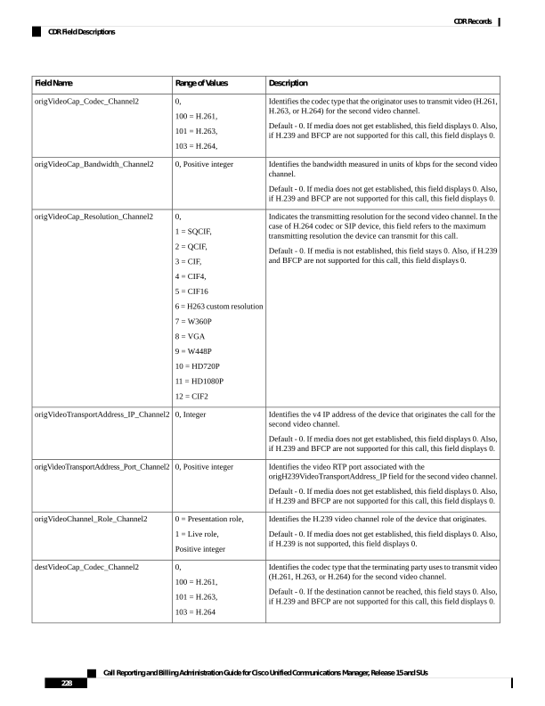
Page 241
Description
Range of Values
Field Name
Identifies the bandwidth measured in units of kbps for the second video
channel.
Default - 0. If media does not get established, this field displays 0. Also,
if H.239 and BFCP are not supported for this call, this field displays 0.
0, Positive integer
destVideoCap_Bandwidth_Channel2
Indicates the transmitting resolution for the second video channel. In the
case of H.264 codec or SIP device, this field refers to the maximum
transmitting resolution the device can transmit for this call.
Default - 0. If media is not established, this field stays 0. Also, if H.239
and BFCP are not supported for this call, this field displays 0.
0,
1 = SQCIF,
2 = QCIF,
3 = CIF,
4 = CIF4,
5 = CIF16
6 = H263 custom resolution
7 = W360P
8 = VGA
9 = W448P
10 = HD720P
11 = HD1080P
12 = CIF2
destVideoCap_Resolution_Channel2
Identifies the v4 IP address of the device that receives the call.
Default - 0. If media does not get established, this field displays 0. Also,
if H.239 and BFCP are not supported for this call, this field displays 0.
0, Integer
destVideoTransportAddress_IP_Channel2
Identifies the video RTP port associated with the
destH239VideoTransportAddress_IP field.
Default - 0. If media does not get established, this field displays 0. Also,
if H.239 and BFCP are not supported for this call, this field displays 0.
0, Positive integer
destVideoTransportAddress_Port_Channel2
Identifies the H.239 video channel role of the device that receives the
call.
Default - 0. If media does not get established, this field displays 0. Also,
if H.239 is not supported, this field displays 0.
0 = Presentation role,
1 = Live role,
Positive integer
destVideoChannel_Role_Channel2
Identifies the protocol (SIP, H.323, CTI/JTAPI, or Q.931) used between
Cisco Unified CM and the upstream voice product in the call path.
0 = Unknown,
1 = SIP,
2 = H323,
3 = CTI/JTAPI,
4 = Q931,
Integer
incomingProtocolID
Identifies the globally unique call reference identification for the protocol.
The value is received from the upstream voice product. The value is
alpha–numeric and truncated to 32 characters.
Varchar(32)
incomingProtocolCallRef
Call Reporting and Billing Administration Guide for Cisco Unified Communications Manager, Release 15 and SUs
229
CDR Records
CDR Field Descriptions
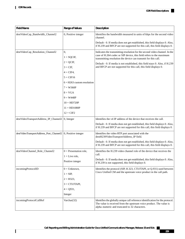
Page 242
Description
Range of Values
Field Name
Identifies the protocol (SIP, H.323, CTI/JTAPI, or Q.931) used between
Cisco Unified CM and the downstream voice product in the call path.
0 = Unknown,
1 = SIP,
2 = H323,
3 = CTI/JTAPI,
4 = Q931,
Integer
outgoingProtocolID
Identifies the globally unique call reference identification for the protocol.
The value is passed to the next downstream voiced product. The value
is alpha–numeric and truncated to 32 characters.
Varchar(32)
outgoingProtocolCallRef
Displays the reason why the call was intercepted for the active call. This
field is used with the external call control feature. See topics related to
routing reason values for external call control for a list of reasons.
Default value is 0.
Positive Integer
For field values see Routing
Reason Values for External
Call Control, on page 236
currentRoutingReason
Displays the reason why the call was intercepted for the first time. This
field is used with the external call control feature, See topics related to
routing reason values for external call control for a list of reasons.
Default value is 0.
Positive Integer
For a complete list of
OnBehalfOf fields, see
OnBehalfof Codes, on page
249
origRoutingReason
Displays why the call was intercepted for the last time. This field is used
with the external call control feature. See topics related to routing reason
values for external call control for a list of reasons.
Default - Empty string.
Positive Integer
For a complete list of
OnBehalfOf fields, see
OnBehalfof Codes, on page
249
lastRedirectingRoutingReason
Indicates the partition for the hunt pilot DN.
Default - Empty string.
Text String
huntPilotPartition
Indicates the hunt pilot DN through which the call is routed.
Default - Empty string.
Text String
huntPilotDN
Call Reporting and Billing Administration Guide for Cisco Unified Communications Manager, Release 15 and SUs
230
CDR Records
CDR Field Descriptions
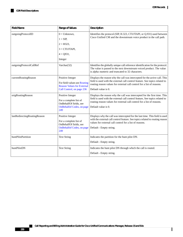
Page 243
Description
Range of Values
Field Name
Indicates the pattern of the called party.
Default value specifies 5 (PATTERN_ROUTE).
• If the huntPilotDN is populated, use the huntPilotDN field value
as the hunt pilot.
• If the huntPilotDN is not available, check the pattern usage (7
=PATTERN_HUNT_PILOT) in the CDR table to identify the call
type. If this call is a hunt list call, use the finalCalledPartyNumber
as the huntPilotDN.
Possible value for the fields:
• 0 CallPark PATTERN_CALL_PARK
• 1 Conference PATTERN_CONF
• 2 Device PATTERN_DEVICE
• 3 Translation PATTERN_TRANSLATION
• 4 Call Pick Up Group PATTERN_CALL_PICK_UP_GROUP
• 5 Route PATTERN_ROUTE
• 6 Message Waiting PATTERN_MESSAGE_WAITING
• 7 Hunt Pilot PATTERN_HUNT_PILOT
• 8 Voice Mail Port PATTERN_VOICE_MAIL_PORT
• 9 Domain Routing PATTERN_ROUTE_DOMAIN
• 10 IPAddress Routing PATTERN_ROUTE_IPNET
• 11 Device template PATTERN_DEVICE_TEMPLATE
• 12 Directed Call Park PATTERN_DIRECTED_CALL_PARK
• 13 Device Intercom PATTERN_DEVICE_INTERCOM
• 14 Translation Intercom PATTERN_TRANSLATION_INTERCOM
• 15 Translation Calling Party Number
PATTERN_TRANSLATION_CALLING_PARTY_NUMBER
• 16 Mobility Handoff PATTERN_MOBILITY_HANDOFF
• 17 Mobility DTMF PATTERN_MOBILITY_DTMF
• 18 Mobility IVR PATTERN_MOBILITY_IVR
• 19 Device Intercom Template
PATTERN_DEVICE_INTERCOM_TEMPLATE
Positive Integer
calledPartyPatternUsage
Call Reporting and Billing Administration Guide for Cisco Unified Communications Manager, Release 15 and SUs
231
CDR Records
CDR Field Descriptions
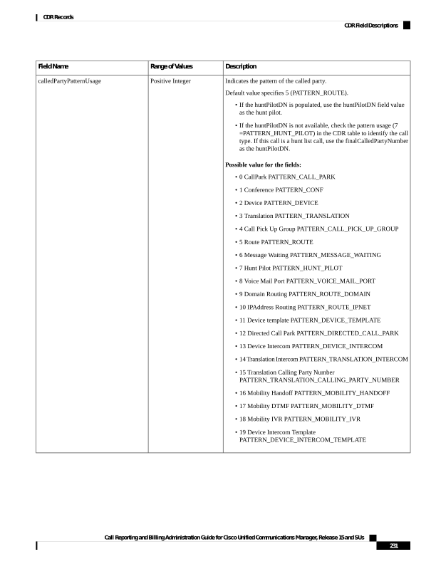
Page 244
Description
Range of Values
Field Name
Specifies alphanumeric string up to 50 characters.
This field is populated with the IMS Identifier(ICID) from the P-Charging
Vector at the incoming call leg of the call.
This field will be empty when the call leg has no IMS or SIP trunk with
P-Charging-Vector enabled.
Default = Empty String " "
Text String
incomingICID
Specifies alphanumeric string up to 50 characters.
This field is populated with the originating Interoperator Identifier(IOI)
from the P-Charging Vector at the incoming call leg of the call.
This field will be empty when the call leg has no IMS or SIP trunk with
P-Charging-Vector enabled.
Default = Empty String " "
Text String
incomingOrigIOI
Specifies alphanumeric string up to 50 characters.
This field is populated with the terminating Interoperator Identifier(IOI)
from the P-Charging Vector at the incoming call leg of the call.
This field will be empty when the call leg has no IMS or SIP trunk with
P-Charging-Vector enabled.
Default = Empty String " "
Text String
incomingTermIOI
Specifies alphanumeric string up to 50 characters.
This field is populated with the IMS Identifier(ICID) from the P-Charging
Vector at the outgoing call leg of the call.
This field will be empty when the call leg has no IMS or SIP trunk with
P-Charging-Vector enabled.
Default = Empty String " "
Text String
outgoingICID
Specifies alphanumeric string up to 50 characters.
This field is populated with the originating Interoperator Identifier(IOI)
from the P-Charging Vector at the outgoing call leg of the call.
This field will be empty when the call leg has no IMS or SIP trunk with
P-Charging-Vector enabled.
Default = Empty String " "
Text String
outgoingOrigIOI
Specifies alphanumeric string up to 50 characters.
This field is populated with the terminating Interoperator Identifier(IOI)
from the P-Charging Vector at the outgoing call leg of the call.
This field will be empty when the call leg has no IMS or SIP trunk with
P-Charging-Vector enabled.
Default = Empty String " "
Text String
outgoingTermIOI
Call Reporting and Billing Administration Guide for Cisco Unified Communications Manager, Release 15 and SUs
232
CDR Records
CDR Field Descriptions
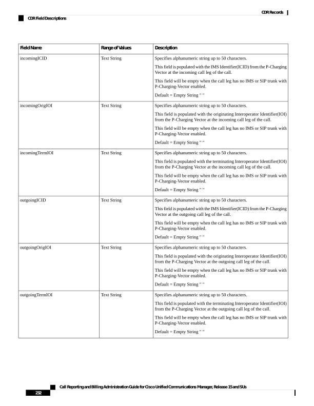
Page 245
Description
Range of Values
Field Name
Specifies alphanumeric string up to 50 characters.
The Original called party number outpulsed from the device. Refer to
section on Redirecting Number Transformation for details.
Default = Empty String " "
Text String
outpulsedOriginalCalledPartyNumber
Specifies alphanumeric string up to 50 characters.
The Last Redirecting number outpulsed from the device. Refer to section
on Redirecting Number Transformation for details.
Default = Empty String " "
Text String
outpulsedLastRedirectingNumber
Specifies whether the call has been put into a queue or not. A value of 0
means that the call is not put into any queue; 1 means the call has been
put into a queue.
Positive Integer
wasCallQueued
Specifies how long a caller has been put into a queue. The value is
specified in second. The value is 0 if the call is never put into any queue.
Positive Integer
totalWaitTimeInQueue
Specifies an alphanumeric string of up to 254 characters that identifies
the calling party if the calling party uses a directory URI for call
addressing.
If the calling party uses a blended address in the identity headers, this
field contains the directory URI portion of the blended address.
Default - Empty string “”. If the calling party does not use a directory
URI, the field stays empty.
Text String
callingPartyNumber_uri
Specifies a string of up to 254 alphanumeric characters that specifies the
directory URI to which the original call was addressed, prior to any call
forwarding, provided the call was addressed to a directory URI.
If a blended address is used for the called party, this field specifies the
directory URI portion of the blended address.
Default - Empty string “”. If destination cannot be reached, or if the called
party is a directory number, this field stays empty.
Text String
originalCalledPartyNumber_uri
Specifies an alphanumeric string of up to 254 characters that indicate the
directory URI address to which the call finally gets presented, if the final
address is a directory URI. If no forwarding occurs, this field shows the
same directory URI as the originalCalledPartyNumber_uri field.
If a blended address is used for the called number, this field specifies the
directory URI portion of the blended address.
For calls to a conference bridge, this field contains the actual identifier
of the conference bridge, which is an alphanumeric string (for example,
b0019901001).
Default - Empty string “”. If destination cannot be reached, or if a
directory number is used for called addressing, this field stays empty.
Text String
finalCalledPartyNumber_uri
Call Reporting and Billing Administration Guide for Cisco Unified Communications Manager, Release 15 and SUs
233
CDR Records
CDR Field Descriptions
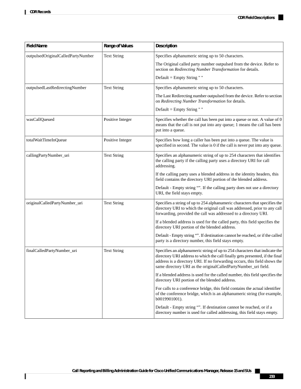
Page 246
Description
Range of Values
Field Name
Specifies an alphanumeric string of up to 254 characters.
For forwarded calls that use a directory URI for addressing, this field
specifies the directory URI of the next to last hop before the call reaches
its final destination. If only one hop occurs, this number matches the
originalCalledPartyNumber_uri.
If a blended address is used, this field contains only the directory URI
portion of the blended address.
For calls that are not forwarded, this field matches the
originalCalledPartyNumber_uri and the finalCalledPartyNumber_uri.
For calls to a conference bridge, this field contains the actual identifier
of the conference bridge, which is an alphanumeric string (for example,
b0019901001).
Default - Empty string “”. If the call is never redirected, or if the address
is a directory number, this field remains empty.
Text String
lastRedirectDn_uri
Specifies the mobile cellular number if the original calling device is a
mobile device.
If the original calling device is not a mobile device, this field remains
empty.
Default - Empty string
Text string
mobileCallingPartyNumber
Specifies the mobile called party if the final called device is a mobile
device.
If the final called device is not a mobile device, this field remains empty.
Default - Empty string
Text string
finalMobileCalledPartyNumber
Specifies the device name of the calling party if the call is placed from
a mobile device.
If the mobile call uses a remote destination profile, the device name is
the mobile number and remote destination profile name. For example,
mobileNumber: RDP-name.
If the mobile device uses a mobile identity, the device name is the mobile
identity name.
If the original device is not a mobile device, this field remains empty.
Default - Empty string
Text string
origMobileDeviceName
Specifies the name of the destination mobile device.
If the mobile device uses a remote destination profile the device name
is the mobile number and remote destination profile name. For example,
mobileNumber: RDP-name.
If the mobile device uses a mobile identity, the device name is the mobile
identity name.
If the destination device is not a mobile device, this field remains empty.
Default - Empty string
Text string
destMobileDeviceName
Call Reporting and Billing Administration Guide for Cisco Unified Communications Manager, Release 15 and SUs
234
CDR Records
CDR Field Descriptions
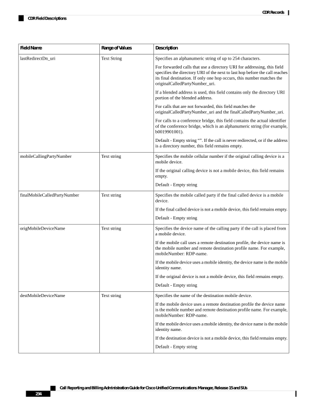
Page 247
Description
Range of Values
Field Name
Specifies the call duration in the mobile network of the originating device
if the calling party is a mobile device.
If the calling party is not a mobile device, this field remains empty.
Default - 0
Positive integer
origMobileCallDuration
Specifies the call duration in the mobile network for the destination device
if the destination device is a mobile device.
If the destination device is not a mobile device, this field remains empty.
Default - 0
Positive integer
destMobileCallDuration
Specifies the mobility feature that is invoked for this mobile call.
Default - 0
Positive integer
mobileCallType
Specifies numeric string (with special characters) up to 50 characters.
This is the pattern to which the original call was placed before any
configured translation is applied.
Calls to Translation Pattern will always populate the pattern after applying
the configured transformation on the translation pattern.
Default—empty string “”.
Text String
originalCalledPartyPattern
Specifies numeric string (with special characters) string up to 50
characters.
The pattern of the final called party to which the call is presented until
that call is answered or ringing has ended. If no forwarding occurred,
this pattern is the same as originalCalledPartyPattern. This field indicates
the pattern before any configured translation rules are applied.
This value is the same as the finalCalledPartyNumber if the number is a
direct match without any translation
Default—empty string “”.
Text String
finalCalledPartyPattern
Specifies numeric string (with special characters) string up to 50
characters.
The pattern of the last party which redirected the call to the current called
party. If there is no redirection, the field has the same value as the
originalCalledPartyPattern.
Default—empty string “”.
Text String
lastRedirectingPartyPattern
Specifies numeric string (with special characters) string up to 50
characters.
The huntPilot pattern as configured in the database. This field is populated
only when the HuntPilot member answers the call which is placed either
directly or due to redirection to the huntPilot.
Default - empty string "". If no huntPilot member answers, this field is
empty.
Text String
huntPilotPattern
Call Reporting and Billing Administration Guide for Cisco Unified Communications Manager, Release 15 and SUs
235
CDR Records
CDR Field Descriptions
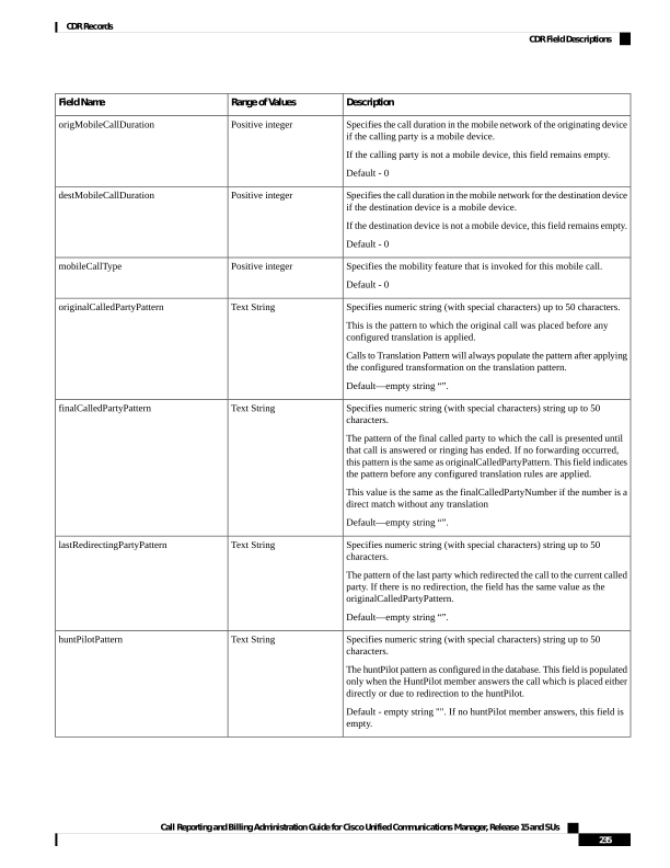
Page 248
Description
Range of Values
Field Name
Indicates whether the device that initiated the call was a Spark client that
is anchored to Cisco Unified Communications Manager over the Spark
Remote Device:
• If yes, this field indicates "CiscoSparkRemoteDevice"
• If no, this field is empty.
Text String
origDeviceType
Indicates whether the device that was called was a Spark client that is
anchored to Cisco Unified Communications Manager over the Spark
Remote Device:
• If yes, this field indicates "CiscoSparkRemoteDevice"
• If no, this field is empty.
Note
If the Spark client "rings" and the CDR Log Calls with Zero Duration
Flag service parameter is True, this field gets populated as
'CiscoSparkRemoteDevice' even if an enterprise number was dialed
with "Ring all shared lines" configured.
Text String
destDeviceType
Indicates the call Session ID of the originating device.
When the session terminates, the system generates a CDR record and the
field is populated with the originating device Session ID for the particular
call.
Note
If the CDR service parameter 'CDR Log Calls with Zero Duration Flag'
is set to 'True', this field is populated even though the call is not
answered.
The maximum length of this field is restricted to 127 characters. For
example, origDeviceSessionID = ab30317fla784dc48fl824d0d3715d86
Default—empty string “”.
Text String
origDeviceSessionID
Indicates the call Session ID of the destination device.
When the session terminates, the system generates a CDR record and the
field is populated with the destination device Session ID for the particular
call.
The maximum length of this field is restricted to 127 characters. For
example, destDeviceSessionID = 47755a9de7794ba387653f2099600ef2
Default—empty string “”.
Text String
destDeviceSessionID
Routing Reason Values for External Call Control
Unified Communications Manager supports the external call control feature, which enables an adjunct route
server to make call-routing decisions for Unified Communications Manager by using the Cisco Unified Routing
Rules Interface. When you configure external call control, Unified Communications Manager issues a route
Call Reporting and Billing Administration Guide for Cisco Unified Communications Manager, Release 15 and SUs
236
CDR Records
Routing Reason Values for External Call Control
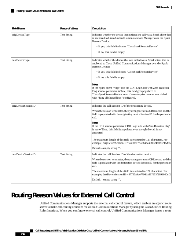
Page 249
request that contains the calling party and called party information to the adjunct route server. The adjunct
route server receives the request, applies appropriate business logic, and returns a route response that instructs
Unified Communications Manager on how the call should get routed, along with any additional call treatment
that should get applied.
The adjunct route server can instruct Unified Communications Manager to allow, divert, or deny the call,
modify calling and called party information, play announcements to callers, reset call history so adjunct
voicemail and IVR servers can properly interpret calling/called party information, and log reason codes that
indicate why calls were diverted or denied.
The following table includes the reasons that can display for the currentRoutingReason, origRoutingReason,
or lastRedirectingRoutingReason fields.
Table 90: Routing Reason Values for External Call Control
Description
Reason
Field Value
This value indicates that the route server did not return
a routing directive to the Unified Communications
Manager.
PDPDecision_NONE
0
This value indicates that Unified Communications
Manager allowed a call.
PDPDecision_Allow_Fulfilled
1
This value indicates that Unified Communications
Manager disallowed a call.
PDPDecision_Allow_Unfulfilled
2
This value indicates that Unified Communications
Manager diverted the call.
PDPDecision_Divert_Fulfilled
3
This value indicates that Unified Communications
Manager was not able to divert the call.
PDPDecision_Divert_Unfulfilled
4
This value indicates that Unified Communications
Manager forwarded the call.
PDPDecision_Forward_Fulfilled
5
This value indicates that Unified Communications
Manager was unable to forward the call.
PDPDecision_Forward_Unfulfilled
6
This value indicates that Unified Communications
Manager rejected the call.
PDPDecision_Reject_Fulfilled
7
This value indicates that Unified Communications
Manager was not able to reject the call.
PDPDecision_Reject_Unfulfilled
8
Cisco Call Detail Records Codes
This chapter section information about the codec types and codes that are used in the Call Detail Record fields.
Codec Types
The following table contains the compression and payload types that may appear in the codec fields.
Call Reporting and Billing Administration Guide for Cisco Unified Communications Manager, Release 15 and SUs
237
CDR Records
Cisco Call Detail Records Codes
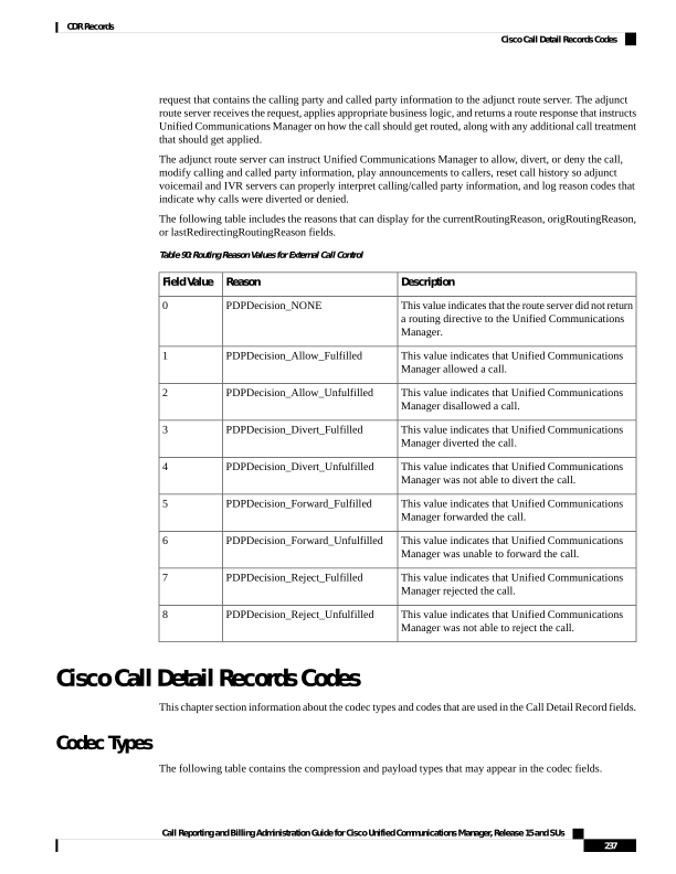
Page 250
Table 91: Codec Types
Description
Value
NonStandard
1
G711Alaw 64k
2
G711Alaw 56k
3
G711mu-law 64k
4
G711mu-law 56k
5
G722 64k
6
G722 56k
7
G722 48k
8
G7231
9
G728
10
G729
11
G729AnnexA
12
Is11172AudioCap
13
Is13818AudioCap
14
G.729AnnexB
15
G.729 Annex AwAnnexB
16
GSM Full Rate
18
GSM Half Rate
19
GSM Enhanced Full Rate
20
Wideband 256K
25
Data 64k
32
Data 56k
33
G7221 32K
40
G7221 24K
41
AAC
42
MP4ALATM_128
43
MP4ALATM_64
44
Call Reporting and Billing Administration Guide for Cisco Unified Communications Manager, Release 15 and SUs
238
CDR Records
Codec Types
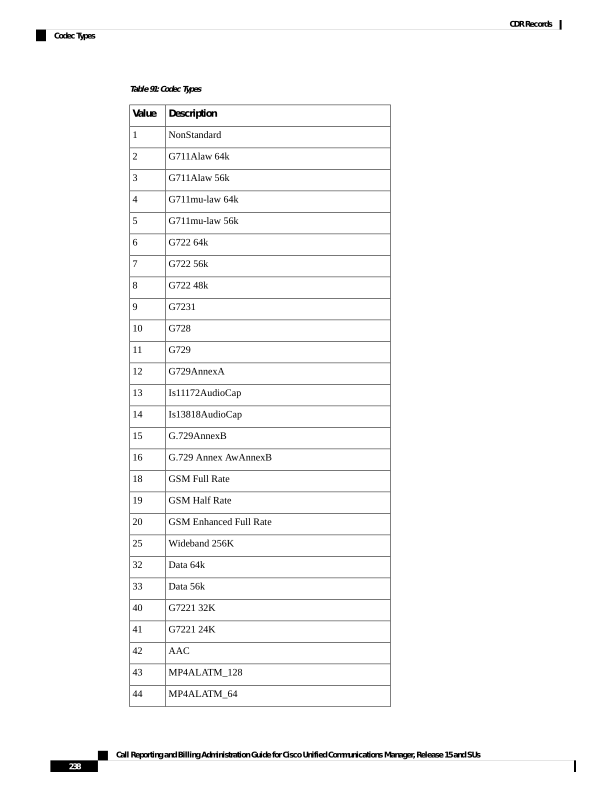
Page 251
Description
Value
MP4ALATM_56
45
MP4ALATM_48
46
MP4ALATM_32
47
MP4ALATM_24
48
MP4ALATM_NA
49
GSM
80-
ActiveVoice
81
G726 32K
82
G726 24K
83
G726 16K
84
iLBC
86
iSAC
89
OPUS
90
H261
100
H263
101
Vieo
102
H264
103
H264_SVC
104
T120
105
H224
106
T38Fax
107
TOTE
108
H265
109
H264_UC
110
XV150_MR_711U
111
NSE_VBD_711U
112
XV150_MR_729A
113
NSE_VBD_729A
114
Call Reporting and Billing Administration Guide for Cisco Unified Communications Manager, Release 15 and SUs
239
CDR Records
Codec Types
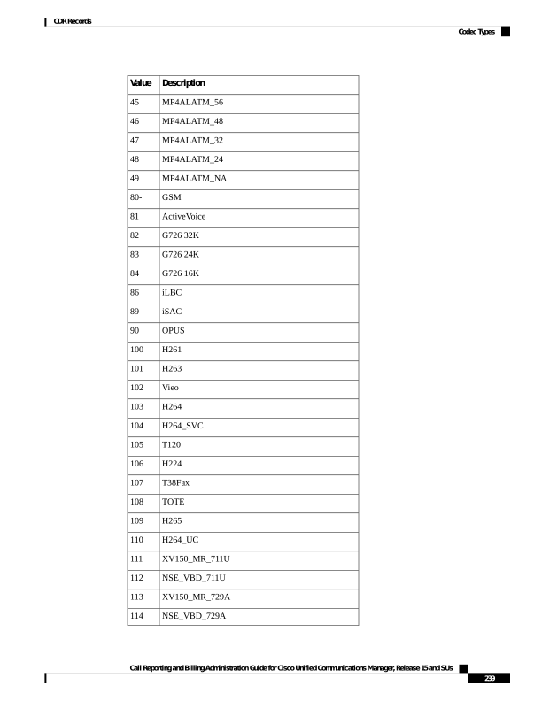
Page 252
Description
Value
H264_FEC
115
Clear_Chan
120
Universal_Xcoder
222
RFC2833_DynPayload
257
PassThrough
258
Dynamic_Payload_PassThru
259
DTMF_OOB
260
Inband_DTMF_RFC2833
261
NoAudio
299
v150_LC_ModemRelay
300
v150_LC_SPRT
301
v150_LC_SSE
302
T38 fax
303
Call Termination Cause Codes
The following tables contain call termination cause codes that may appear in the Cause fields in CDRs.
Cause Code is defined in call control as Natural number. It is a 32 bit unsigned (long) positive integer with
values ranging from 0 to +4,294,967,295.
Note
Table 92: Call Termination Cause Codes
Description
Code
No error
0
Unallocated (unassigned) number
1
No route to specified transit network (national use)
2
No route to destination
3
Send special information tone
4
Misdialed trunk prefix (national use)
5
Channel unacceptable
6
Call Reporting and Billing Administration Guide for Cisco Unified Communications Manager, Release 15 and SUs
240
CDR Records
Call Termination Cause Codes

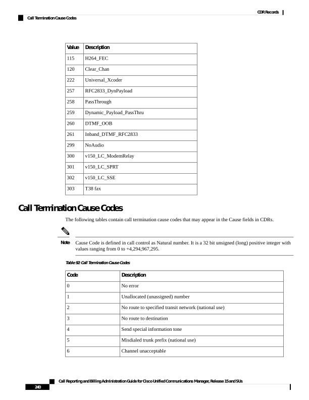
Page 253
Description
Code
Call awarded and being delivered in an established channel
7
Preemption
8
Preemption—circuit reserved for reuse
9
Normal call clearing
16
User busy
17
No user responding
18
No answer from user (If "No Answer Ring duration" value is greater than the
T301 Timer value and after T301 Timer expiry, Call Forwarding No
Answer(CFNA) Feature would be invoked).
19
Subscriber absent
20
Call rejected
21
Number changed
22
Natural Exchange Routing Error
25
Non-selected user clearing
26
Destination out of order
27
Invalid number format (address incomplete)
28
Facility rejected
29
Response to STATUS ENQUIRY
30
Normal, unspecified
31
No circuit/channel available
34
Network out of order
38
Permanent frame mode connection out of service
39
Permanent frame mode connection operational
40
Temporary failure
41
Switching equipment congestion
42
Access information discarded
43
Requested circuit/channel not available
44
Precedence call blocked
46
Resource unavailable, unspecified
47
Call Reporting and Billing Administration Guide for Cisco Unified Communications Manager, Release 15 and SUs
241
CDR Records
Call Termination Cause Codes
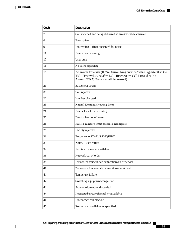
Page 254
Description
Code
Quality of Service not available
49
Requested facility not subscribed
50
Service operation violated
53
Incoming calls barred
54
Incoming calls barred within Closed User Group (CUG)
55
Bearer capability not authorized
57
Bearer capability not presently available
58
Inconsistency in designated outgoing access information and subscriber class
62
Service or option not available, unspecified
63
Bearer capability not implemented
65
Channel type not implemented
66
Requested facility not implemented
69
Only restricted digital information bearer capability is available (national use)
70
Service or option that is not implemented, unspecified
79
Invalid call reference value
81
Identified channel does not exist
82
A suspended call exists, but this call identity does not
83
Call identity in use
84
No call suspended
85
Call having the requested call identity has been cleared
86
User not member of CUG (Closed User Group)
87
Incompatible destination
88
Destination number missing and DC not subscribed
90
Invalid transit network selection (national use)
91
Invalid message, unspecified
95
Mandatory information element is missing
96
Message type nonexistent or not implemented
97
Call Reporting and Billing Administration Guide for Cisco Unified Communications Manager, Release 15 and SUs
242
CDR Records
Call Termination Cause Codes
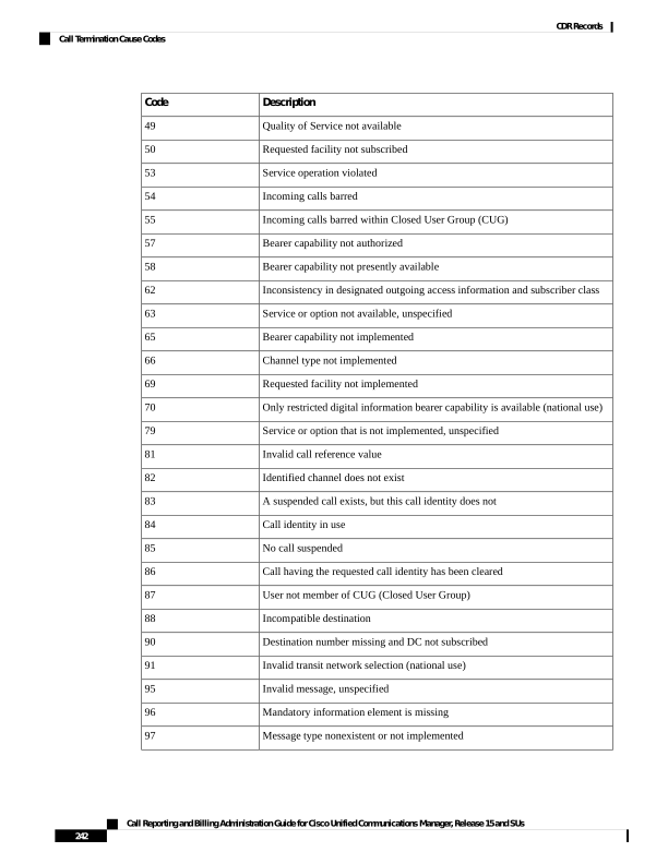
Page 255
Description
Code
Message is not compatible with the call state, or the message type is nonexistent
or not implemented
98
An information element or parameter does not exist or is not implemented
99
Invalid information element contents
100
The message is not compatible with the call state
101
Call terminated when timer expired; a recovery routine that is executed to recover
from the error
102
Parameter nonexistent or not implemented - passed on (national use)
103
Message with unrecognized parameter discarded
110
Protocol error, unspecified
111
Precedence Level Exceeded
122
Device not Preemptable
123
Out of bandwidth (Cisco specific)
125
Call split (Cisco specific)
126
Interworking, unspecified
127
Precedence out of bandwidth
129
Natural Isolated Code
130
Call Control Discovery PSTN Failover (Cisco specific)
131
IME QOS Fallback (Cisco specific)
132
PSTN Fallback locate Call Error (Cisco specific)
133
PSTN Fallback wait for DTMF Timeout (Cisco specific)
134
IME Failed Connection Timed out (Cisco specific)
135
IME Failed not enrolled (Cisco specific)
136
IME Failed socket error (Cisco specific)
137
IME Failed domain blocked (Cisco specific)
138
IME Failed prefix blocked (Cisco specific)
139
IME Failed expired ticket (Cisco specific)
140
IME Failed remote no matching route (Cisco specific)
141
IME Failed remote unregistered (Cisco specific)
142
Call Reporting and Billing Administration Guide for Cisco Unified Communications Manager, Release 15 and SUs
243
CDR Records
Call Termination Cause Codes
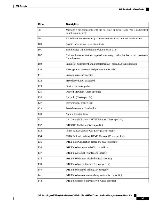
Page 256
Description
Code
IME Failed remote IME disabled (Cisco specific)
143
IME Failed remote invalid IME trunk URI (Cisco specific)
144
IME Failed remote URI not E164 (Cisco specific)
145
IME Failed remote called number not available (Cisco specific)
146
IME Failed Invalid Ticket (Cisco specific)
147
IME Failed unknown (Cisco specific)
148
DCC Allowed Percentage Exceeded
155
Table 93: Cisco-Specific Call Termination Cause Codes
Description
Hex Value Code
Decimal Value Code
Conference Full (was 124)
0x40000
262144
Call split (was 126) This code applies when a call
terminates during a transfer operation because it was
split off and terminated (was not part of the final
transferred call). This code can help you to determine
which calls terminated as part of a feature operation.
0x60000
393216
Conference drop any party/Conference drop last party
(was 128)
0x70000
458752
CCM_SIP_400_BAD_REQUEST
0x1000029
16777257
CCM_SIP_401_UNAUTHORIZED
0x2000015
33554453
CCM_SIP_402_PAYMENT_REQUIRED
0x3000015
50331669
CCM_SIP_403_FORBIDDEN
0x4000015
67108885
CCM_SIP_404_NOT_FOUND
0x5000001
83886081
CCM_SIP_405_METHOD_NOT_ALLOWED
0x600003F
100663359
CCM_SIP_406_NOT_ACCEPTABLE
0x700004F
117440591
CCM_SIP_407_PROXY_AUTHENTICATION_REQUIRED
0x8000015
134217749
CCM_SIP_408_REQUEST_TIMEOUT
0x9000066
150995046
CCM_SIP__410_GONE
0xB000016
184549398
CCM_SIP_411_LENGTH_REQUIRED
0xC00007F
201326719
CCM_SIP_413_REQUEST_ENTITY_TOO_LONG
0xE00007F
234881151
CCM_SIP_414_REQUEST_URI_TOO_LONG
0xF00007F
251658367
Call Reporting and Billing Administration Guide for Cisco Unified Communications Manager, Release 15 and SUs
244
CDR Records
Call Termination Cause Codes
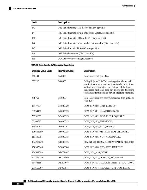
Page 257
Description
Hex Value Code
Decimal Value Code
CCM_SIP_415_UNSUPPORTED_MEDIA_TYPE
0x1000004F
268435535
CCM_SIP_416_UNSUPPORTED_URI_SCHEME
0x1100007F
285212799
CCM_SIP_420_BAD_EXTENSION
0x1500007F
83886207
CCM_SIP_421_EXTENSION_REQUIRED
0x1600007F
369098879
CCM_SIP_423_INTERVAL_TOO_BRIEF
0x1800007F
402653311
CCM_SIP_424_BAD_LOCATION_INFO
0x19000015
419430421
CCM_SIP_429_PROVIDE_REFER_IDENTITY
0x1E000015
503316501
CCM_SIP_480_TEMPORARILY_UNAVAILABLE
0x40000012
1073741842
CCM_SIP_481_CALL_LEG_DOES_NOT_EXIST
0x41000029
1090519081
CCM_SIP_482_LOOP_DETECTED = 0x42000000
- EXCHANGE_ROUTING_ERROR
0x42000019
1107296281
CCM_SIP_483_TOO_MANY_HOOPS
0x43000019
1124073497
CCM_SIP_484_ADDRESS_INCOMPLETE
0x4400001C
1140850716
CCM_SIP_485_AMBIGUOUS
0x45000001
1157627905
CCM_SIP_486_BUSY_HERE
0x46000011
1174405137
CCM_SIP_487_REQUEST_TERMINATED
0x4700001F
1191182367
CCM_SIP_488_NOT_ACCEPTABLE_HERE
0x4800001F
1207959583
CCM_SIP_491_REQUEST_PENDING
0x4B000011
1258291217
CCM_SIP_493_UNDECIPHERABLE
0x4D000011
1291845649
CCM_SIP_500_SERVER_INTERNAL_ERROR
0x54000029
1409286185
CCM_SIP_502_BAD_GATEWAY
0x56000026
1442840614
CCM_SIP_503_SERVICE_UNAVAILABLE
0x57000029
1459617833
CCM_SIP_503_SERVICE_UNAVAILABLE_SER_OPTION_NOAV
0xA700003F
2801795135
CCM_SIP__504_SERVER_TIME_OUT
0x58000066
1476395110
CCM_SIP_505_SIP_VERSION_NOT_SUPPORTED
0x5900007F
1493172351
CCM_SIP_513_MESSAGE_TOO_LARGE
0x5A00007F
1509949567
CCM_SIP_600_BUSY_EVERYWHERE
0xA1000011
2701131793
CCM_SIP_603_DECLINE
0xA2000015
2717909013
Call Reporting and Billing Administration Guide for Cisco Unified Communications Manager, Release 15 and SUs
245
CDR Records
Call Termination Cause Codes
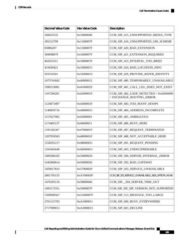
Page 258
Description
Hex Value Code
Decimal Value Code
CCM_SIP_604_DOES_NOT_EXIST_ANYWHERE
0xA3000001
2734686209
CCM_SIP_606_NOT_ACCEPTABLE
0xA400001F
2751463455
CTI_REQUEST_INVALID_PRIMARY_CALL_STATE
0xA0000
655360
PREEMPTION_NON_IP
0xD0008
851976
PREEMPTION_NETWORK
0xE0008
917512
CCM_SIP_417_ERR_RESOURCE_PRIORITY_ROUTINE
0x1200003F
301989951
CCM_SIP_433_ANONYMITY_DISALLOWED
0x22000015
570425365
Redirect Reason Codes
The following table contains the available Redirect Reason Codes that may appear in a record.
Q.931 Standard Redirect Reason Codes
Description
Value
Unknown
0
Call Forward Busy
1
Call Forward No Answer
2
Call Transfer
4
Call Pickup
5
Call Park
7
Call Park Pickup
8
CPE Out of Order
9
Call Forward
10
Call Park Reversion
11
Call Forward all
15
Nonstandard Redirect Reason Codes
Call Deflection
18
Blind Transfer
34
Call Immediate Divert
50
Call Forward Alternate Party
66
Call Reporting and Billing Administration Guide for Cisco Unified Communications Manager, Release 15 and SUs
246
CDR Records
Redirect Reason Codes
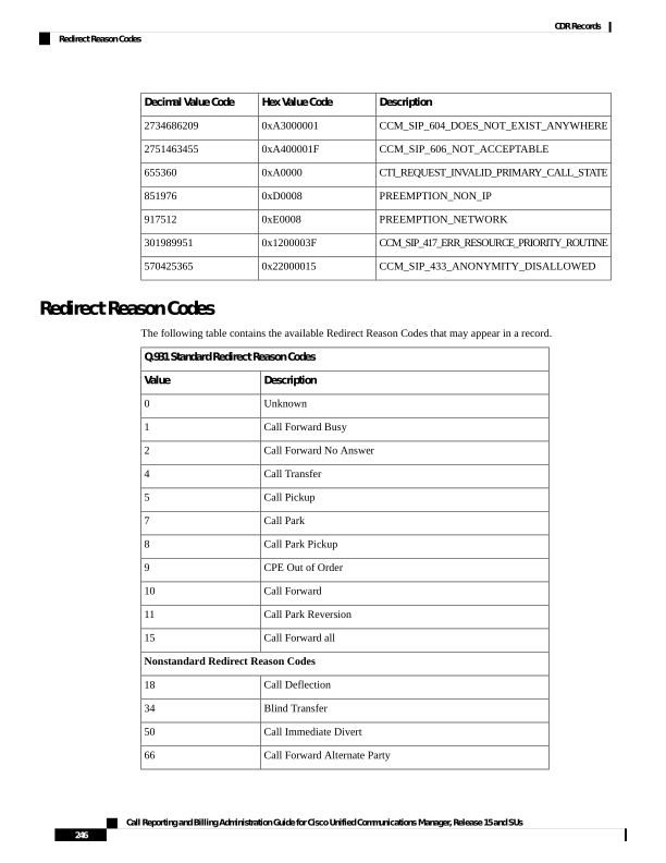
Page 259
Q.931 Standard Redirect Reason Codes
Description
Value
Call Forward On Failure
82
Conference
98
Barge
114
Aar
129
Refer
130
Replaces
146
Redirection (3xx)
162
SIP-forward busy greeting
177
Call Forward Unregistered
178
Follow Me (SIP-forward all greeting)
207
Out of Service (SIP-forward busy greeting)
209
Time of Day (SIP-forward all greeting)
239
Do Not Disturb (SIP-forward no answer greeting)
242
Unavailable (SIP-forward busy greeting)
257
Away (SIP-forward no answer greeting)
274
Mobility HandIn
303
Mobility HandOut
319
Mobility Follow Me
335
Mobility Redial
351
Recording
354
Monitoring
370
Mobility IVR
399
Mobility DVOR
401
Mobility EFA
402
Mobility Session Handoff
403
Mobility Cell Pickup
415
Click to Conference
418
Call Reporting and Billing Administration Guide for Cisco Unified Communications Manager, Release 15 and SUs
247
CDR Records
Redirect Reason Codes
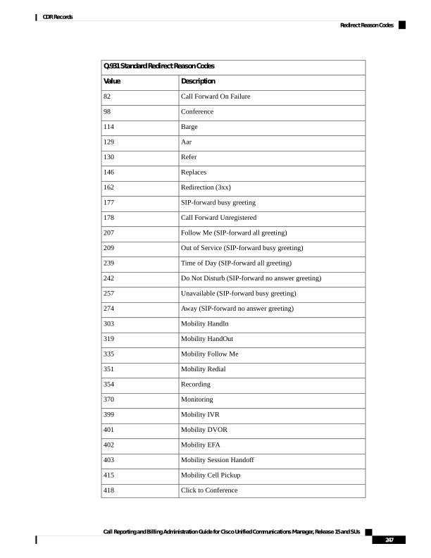
Page 260
Q.931 Standard Redirect Reason Codes
Description
Value
Forward No Retrieve
434
Forward No Retrieve Send Back to Parker
450
Call Control Discovery (indicates that the call is redirected to a
PSTN failover number)
464
Intercompany Media Engine (IME)
480
IME Connection Timed Out
496
IME Not Enrolled
512
IME Socket Error
528
IME Domain Blacklisted
544
IME Prefix Blacklisted
560
IME Expired Ticket
576
IME Remote No Matching Route
592
IME Remote Unregistered
608
IME Remote IME Disabled
624
IME Remote Invalid IME Trunk URI
640
IME Remote URI not E164
656
IME Remote Called Number Not Available
672
IME Invalid Ticket
688
IME Unknown
704
IME PSTN Fallback
720
Presence Enabled Routing
738
Agent Greeting
752
NuRD
783
Native Call Queuing, queue a call
786
Native Call Queuing, de-queue a call
802
Native Call Queuing, redirect to the second destination when no
agent is logged in
818
Call Reporting and Billing Administration Guide for Cisco Unified Communications Manager, Release 15 and SUs
248
CDR Records
Redirect Reason Codes
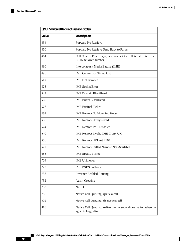
Page 261
Q.931 Standard Redirect Reason Codes
Description
Value
Native Call Queuing, redirect to the second destination when the
queue is full
834
Native Call Queuing, redirect to the second destination when the
maximum wait time in queue is reached
850
OnBehalfof Codes
The following table contains the available OnBehalfof Codes that may appear in a CDR record.
Table 94: OnBehalfof Codes
Description
Value
Unknown
0
CctiLine
1
Unicast Shared Resource Provider
2
Call Park
3
Conference
4
Call Forward
5
Meet-Me Conference
6
Meet-Me Conference Intercepts
7
Message Waiting
8
Multicast Shared Resource Provider
9
Transfer
10
SSAPI Manager
11
Device
12
Call Control
13
Immediate Divert
14
Barge
15
Pickup
16
Refer
17
Replaces
18
Call Reporting and Billing Administration Guide for Cisco Unified Communications Manager, Release 15 and SUs
249
CDR Records
OnBehalfof Codes
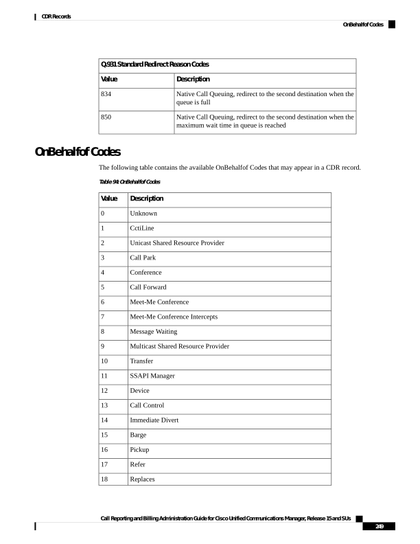
Page 262
Description
Value
Redirection
19
Callback
20
Path Replacement
21
FacCmc Manager
22
Malicious Call
23
Mobility
24
Aar
25
Directed Call Park
26
Recording
27
Monitoring
28
CCDRequestingService
29
Intercompany Media Engine
30
FallBack Manager
31
Presence Enabled Routing
32
AgentGreeting
33
NativeCallQueuing
34
MobileCallType
35
Call Reporting and Billing Administration Guide for Cisco Unified Communications Manager, Release 15 and SUs
250
CDR Records
OnBehalfof Codes

Page 263
C H A P T E R 10
CDR Examples
This chapter provides examples of the call detail records (CDRs) that the Unified Communications
ManagerRelease system generates for all call types. You can use this information for post-processing activities
such as generating billing records and network analysis.
When you install your system, the system enables CDRs by default. You can enable or disable CDRs at any
time that the system is in operation. You do not need to restart Unified Communications Manager for the
change to take effect. The system responds to all changes within a few seconds.
• AAC Calls, on page 252
• Abandoned Calls, on page 254
• Ad Hoc Conference Linking, on page 256
• Agent Greeting Calls, on page 266
• Barge, on page 267
• Call Monitoring, on page 269
• Call Park, on page 271
• Call Pickup, on page 273
• Call Recording, on page 275
• Call Secured Status, on page 277
• Calling Party Normalization, on page 278
• Calls with Busy or Bad Destinations, on page 279
• cBarge, on page 280
• Client Matter Code (CMC), on page 282
• Conference Calls, on page 283
• Conference Now Calls, on page 287
• Conference Drop Any Party, on page 289
• DTMF Method, on page 290
• End-to-End Call Trace, on page 291
• Forced Authorization Code (FAC), on page 295
• Forwarded or Redirected Calls, on page 297
• Hunt List Support, on page 299
• H.239, on page 302
• iLBC Calls, on page 303
• Intercompany Media Engine, on page 306
• Immediate Divert (to Voice-Messaging System), on page 310
• IMS Application Server, on page 312
Call Reporting and Billing Administration Guide for Cisco Unified Communications Manager, Release 15 and SUs
251

Page 264
• Intercom Calls, on page 313
• IPv6 Calls, on page 314
• Legacy Call Pickup, on page 319
• Local Route Groups and Called Party Transformation, on page 320
• Logical Partitioning Calls, on page 321
• Malicious Calls, on page 323
• Meet-Me Conferences, on page 323
• Mobility, on page 324
• Native Call Queuing, on page 337
• Normal Calls (Cisco Unified IP Phone to Cisco Unified IP Phone), on page 338
• Original Calling Party on Transfer, on page 339
• Personal Assistant Calls, on page 340
• Precedence Calls (MLPP), on page 346
• Redirection (3xx) Calls, on page 347
• Redirecting Number Transformation, on page 348
• Refer Calls, on page 349
• Replaces Calls, on page 349
• RSVP, on page 351
• Secure Conference Meet-Me, on page 352
• Short Calls, on page 353
• SIP Call with URL in CallingPartyNumber Field, on page 353
• Successful on Net Calls, on page 354
• Transferred Calls, on page 354
• Video Calls, on page 357
• Video Conference Calls, on page 358
AAC Calls
Advanced Audio Coding-Low Delay (AAC-LD) is a super-wideband codec that provides excellent speech
and music quality at various bit rates. The audio quality scales up with the bit rate. Two mutually incompatible
RTP payload formats are supported: mpeg4-generic and MP4A-LATM.
For AAC-LD (mpeg4-generic) calls, the codec type (payload capability) value 42 is used.
For AAC-LD (MP4A-LATM) calls, a separate codec type value is used for each supported bit rate. The codec
type values are 43 (128K), 44 (64K), 45 (56K), 46 (48K), 47 (32K), and 48 (24K).
The system adds an audio bandwidth field to the CDR for AAC-LD calls.
Definitions
Field Names
This integer field contains the audio bandwidth.
origMediaCap_bandwidth
This integer field contains the audio bandwidth.
destMediaCap_bandwidth
The system populates the bandwidth fields based on the following table:
Bandwidth
Codec
64
G711Alaw64k
Call Reporting and Billing Administration Guide for Cisco Unified Communications Manager, Release 15 and SUs
252
CDR Records
AAC Calls
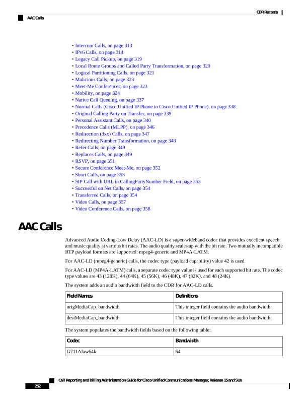
Page 265
Bandwidth
Codec
56
G711Alaw56k
64
G711mu-law64k
56
G711mu-law56k
64
G722 64k
56
G722 56k
48
G722 48k
7
G7231
16
G728
8
G729
8
G729AnnexA
0
Is11172AudioCap
0
Is13818AudioCap
8
G729AnnexB
8
G729AnnexAwAnnexB
13
GSM Full Rate
7
GSM Half Rate
13
GSM Enhanced Full Rate
256
Wideband 256K
64
Data 64k
56
Data 56k
32
G7221 32K
24
G7221 24K
256
AAC-LD (mpeg4-generic)
128
AAC-LD (MP4A-LATM) 128K
64
AAC-LD (MP4A-LATM) 64K
56
AAC-LD (MP4A-LATM) 56K
48
AAC-LD (MP4A-LATM) 48K
32
AAC-LD (MP4A-LATM) 32K
Call Reporting and Billing Administration Guide for Cisco Unified Communications Manager, Release 15 and SUs
253
CDR Records
AAC Calls
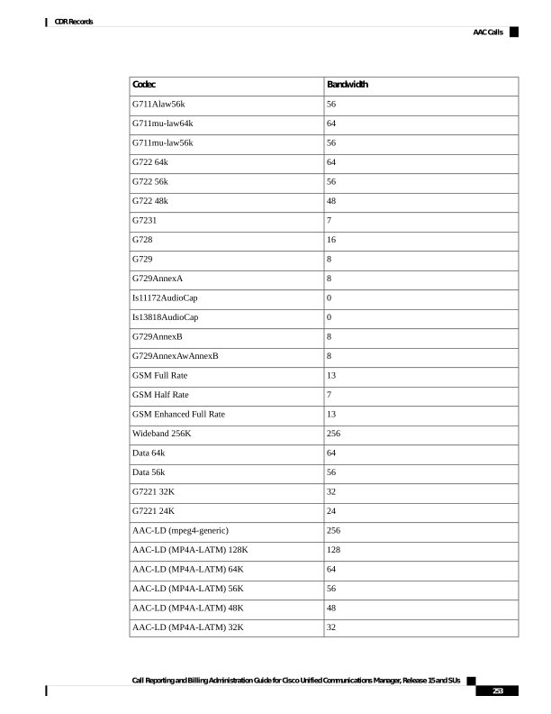
Page 266
Bandwidth
Codec
24
AAC-LD (MP4A-LATM) 24K
13
GSM
15 or 13
iLBC
32
iSAC
8
XV150 MR 729A
8
NSE VBD 729A
AAC-LD (mpeg4-generic) Calls CDR Example
This example applies to a call with AAC-LD (mpeg4-generic) codec:
AAC CDR
Field Names
121
globalCallID_callId
101
origLegCallIdentifier
102
destLegIdentifier
51234
callingPartyNumber
57890
originalCalledPartyNumber
57890
finalCalledPartyNumber
57890
lastRedirectDn
0
origCause_Value
16
dest_CauseValue
42
origMediaCap_payloadCapability
256
origMediaCap_Bandwidth
42
destMediaCap_payloadCapability
256
destMediaCap_Bandwidth
Abandoned Calls
The logging of calls with zero duration represents an optional action. If logging calls with zero duration is
enabled, the following actions occur:
• All calls generate a CDR.
Call Reporting and Billing Administration Guide for Cisco Unified Communications Manager, Release 15 and SUs
254
CDR Records
Abandoned Calls
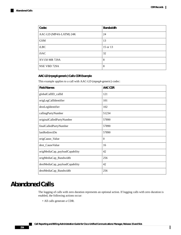
Page 267
• If the call is abandoned, such as when a phone is taken off hook and placed back on hook, various fields
do not contain data. In this case, the originalCalledPartyNumber, finalCalledPartyNumber, the partitions
that are associated with them, the destIpAddr, and the dateTimeConnect fields all remain blank. All calls
that are not connected have a duration of 0 second. When a call is abandoned, the cause code contains
0.
• If the user dials a directory number and abandons the call before it connects, the FirstDest and FinalDest
fields and their associated partitions contain the directory number and the partition to which the call
would have been extended. The DestIp field remains blank, and the duration specifies 0 second.
You must enable the CDR Log Calls With Zero Duration Flag service parameter to log calls with zero duration.
This parameter enables or disables the logging of CDRs for calls which lasted less than 1 second. See Configure
CDR Service Parameters, on page 24 for more information.
Note
Examples of Abandoned Calls
1.
Extension 2001 goes off hook, then on hook.
CDR
Field Names
1
globalCallID_callId
100
origLegCallIdentifier
0
destLegIdentifier
2001
callingPartyNumber
originalCalledPartyNumber
finalCalledPartyNumber
lastRedirectDn
16
origCause_Value
0
dest_CauseValue
0
duration
2.
Extension 2001 calls 2309, but 2001 hangs up (abandons) the call before it is answered.
CDR
Field Names
2
globalCallID_callId
200
origLegCallIdentifier
201
destLegIdentifier
2001
callingPartyNumber
Call Reporting and Billing Administration Guide for Cisco Unified Communications Manager, Release 15 and SUs
255
CDR Records
Abandoned Calls

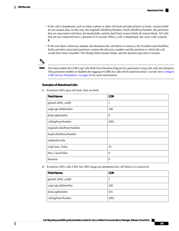
Page 268
CDR
Field Names
2309
originalCalledPartyNumber
2309
finalCalledPartyNumber
2309
lastRedirectDn
16
origCause_Value
0
dest_CauseValue
0
duration
Ad Hoc Conference Linking
The advanced ad hoc conference linking feature allows you to link multiple ad hoc conferences together by
adding an ad hoc conference to another ad hoc conference as if it were an individual participant. You can also
use the methods that are available for adding individual participants to an ad hoc conference to add another
conference to an ad hoc conference.
CDRs that the advanced ad hoc conference linking feature generates include a field that is called
OrigConversationId. This field associates the conference bridges that are involved in a linked conference.
The Comment field of the CDR adds the ConfRequestorDN and ConfRequestorDeviceName tags to indicate
add/drop of participants of the conference by a non-controller of the conference.
The following scenarios show some of the various CDRs:
Conference Linking Using Join
The direction of the call between the bridges depends upon which of the two calls that involve Carol is primary.
The primary call survives, and the secondary call gets redirected to the conference.
Alice calls Bob, and Bob conferences in Carol (Conference 1). Dave calls Carol, and conferences in Ed
(Conference 2). Two separate conferences get created. Carol exists in both conferences. At this point, CDR1,
CDR2, CDR3, and CDR4 get generated.
Carol joins the two conferences. At this point, CDR5 gets generated.
When the remaining parties hang up, the remaining CDRs get generated in the order that the parties leave the
conference.
Conference Linking Using Join Example
CDR6: Dave ->
Conference Bridge
(conference call)
CDR5: Carol ->
Conference Bridge
(conference call)
CDR4: Dave -> Ed
(consultation call)
CDR3: Dave -> Carol
(original call)
CDR2: Bob -> Carol
(consultation call)
CDR1: Alice -> Bob
(original call)
Field Names
3
3
4
3
2
1
globalCallID_callId
22
22
23
21
13
11
origLegCallIdentifier
26
25
24
22
14
12
destLegIdentifier
Call Reporting and Billing Administration Guide for Cisco Unified Communications Manager, Release 15 and SUs
256
CDR Records
Ad Hoc Conference Linking
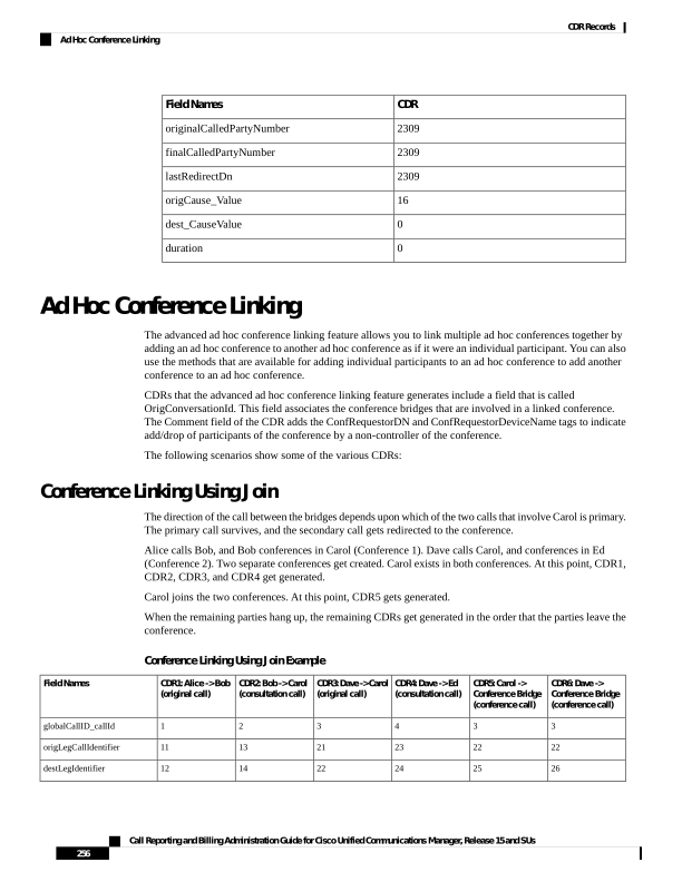
Page 269
CDR6: Dave ->
Conference Bridge
(conference call)
CDR5: Carol ->
Conference Bridge
(conference call)
CDR4: Dave -> Ed
(consultation call)
CDR3: Dave -> Carol
(original call)
CDR2: Bob -> Carol
(consultation call)
CDR1: Alice -> Bob
(original call)
Field Names
1003
1002
1003
1003
1001
1000
callingPartyNumber
b0029901222
b0029901222
1004
1002
1002
1001
originalCalledPartyNumber
b0029901222
b0029901222
1004
1002
1002
1001
finalCalledPartyNumber
1003
1003
1004
1002
1002
1001
lastRedirectDn
4
4
4
4
4
4
origTerminationOnBehalfOf
4
4
4
4
4
4
destTerminationOnBehalfOf
98
98
0
0
0
0
lastRedirectRedirectReason
4
4
0
0
0
0
lastRedirectRedirectOnBehalfOf
0
0
0
0
0
0
origConversationID
2222
2222
0
0
0
0
destConversationID
ConfControll
erDn=1003;Co
nfController
DeviceName=S
EP0003E333FA
D1;ConfReque
storDn-1003;
ConfRequesto
rDeviceName=
SEP0003E333F
AD1
ConfControll
erDn=1001;Co
nfController
DeviceName=S
EP0003E333FE
BD;ConfReque
storDn-1001;
ConfRequesto
rDeviceName=
SEP0003E333F
EBD
Comment
CDR11: Bob ->
Conference Bridge
(conference call)
CDR10: Alice ->
Conference Bridge
(conference call)
CDR9: Conference
Bridge (conference
call)
CDR8: Ed -> Conference
Bridge (conference
call)
CDR7: Dave ->
Conference Bridge
(conference call)
Field Names
1
1
1
3
3
globalCallID_callId
12
11
17
24
21
origLegCallIdentifier
16
15
28
27
26
destLegIdentifier
1001
1000
b0029901001
1004
1003
callingPartyNumber
b0029901001
b0029901001
b0029901222
b0029901222
b0029901222
originalCalledPartyNumber
b0029901001
b0029901001
b0029901222
b0029901222
b0029901222
finalCalledPartyNumber
1001
1001
1002
1003
1003
lastRedirectDn
0
0
0
0
0
origTerminationOnBehalfOf
0
0
0
0
0
destTerminationOnBehalfOf
98
98
4
98
98
lastRedirectRedirectReason
4
4
10
4
4
lastRedirectRedirectOnBehalfOf
0
0
0
0
0
origConversationID
Call Reporting and Billing Administration Guide for Cisco Unified Communications Manager, Release 15 and SUs
257
CDR Records
Conference Linking Using Join

Page 270
CDR11: Bob ->
Conference Bridge
(conference call)
CDR10: Alice ->
Conference Bridge
(conference call)
CDR9: Conference
Bridge (conference
call)
CDR8: Ed -> Conference
Bridge (conference
call)
CDR7: Dave ->
Conference Bridge
(conference call)
Field Names
2222
2222
2222
2222
2222
destConversationID
ConfControll
erDn=1001;Co
nfController
DeviceName=S
EP0003E333FE
BD;ConfReque
storDn-1001;
ConfRequesto
rDeviceName=
SEP0003E333F
EBD
ConfControll
erDn=1001;Co
nfController
DeviceName=S
EP0003E333FE
BD;ConfReque
storDn-1001;
ConfRequesto
rDeviceName=
SEP0003E333F
EBD
ConfControll
erDn=1003;Co
nfController
DeviceName=S
EP0003E333FA
D1;ConfReque
storDn-1003;
ConfRequesto
rDeviceName=
SEP0003E333F
AD1
ConfControll
erDn=1003;Co
nfController
DeviceName=S
EP0003E333FA
D1;ConfReque
storDn-1003;
ConfRequesto
rDeviceName=
SEP0003E333F
AD1
ConfControll
erDn=1003;Co
nfController
DeviceName=S
EP0003E333FA
D1;ConfReque
storDn-1003;
ConfRequesto
rDeviceName=
SEP0003E333F
AD1
Comment
Conference Linking Using Transfer or Direct Transfer
Alice calls Bob, and Bob conferences Carol (Conference 1). Dave calls Carol and conferences in Ed (Conference
2). Two separate conferences get created; Carol exists in both conferences. At this point, CDR1, CDR2, CDR3,
and CDR4 get generated.
Carol presses the Direct Transfer (DirTrfr) softkey on the call to the first conference. Alice and Bob exist
in Conference 1 while Dave and Ed are in Conference 2. When the remaining parties hang up, the remaining
CDRs get generated in the order in which the parties leave the conference.
The direction of the call between the bridges depends on which of the two calls that involve Carol is the
primary call. The primary call side represents the calling party of the transferred call.
Note
Conference Linking Using Transfer or Direct Transfer Example
CDR6: Carol ->
Conference Bridge
(conference call)
CDR5: Carol ->
Conference Bridge
(conference call)
CDR4: Dave -> Carol
(consultation call)
CDR3: Dave -> Carol
(original call)
CDR2: Bob -> Carol
(consultation call)
CDR1: Alice -> Bob
(original call)
Field Names
3
1
4
3
2
1
globalCallID_callId
22
14
23
21
13
11
origLegCallIdentifier
25
17
24
22
14
12
destLegIdentifier
1003
1002
1003
1003
1001
1000
callingPartyNumber
b0029901222
b0029901001
1004
1002
1002
1001
originalCalledPartyNumber
b0029901222
b0029901001
1004
1002
1002
1001
finalCalledPartyNumber
1003
1001
1004
1002
1002
1001
lastRedirectDn
10
10
4
4
4
4
origTerminationOnBehalfOf
10
10
4
4
4
4
destTerminationOnBehalfOf
98
98
0
0
0
0
lastRedirectRedirectReason
Call Reporting and Billing Administration Guide for Cisco Unified Communications Manager, Release 15 and SUs
258
CDR Records
Conference Linking Using Transfer or Direct Transfer

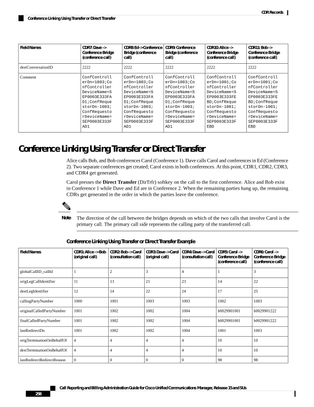
Page 271
CDR6: Carol ->
Conference Bridge
(conference call)
CDR5: Carol ->
Conference Bridge
(conference call)
CDR4: Dave -> Carol
(consultation call)
CDR3: Dave -> Carol
(original call)
CDR2: Bob -> Carol
(consultation call)
CDR1: Alice -> Bob
(original call)
Field Names
4
4
0
0
0
0
lastRedirectRedirectOnBehalfOf
0
0
0
0
0
0
origConversationID
2222
1111
0
0
0
0
destConversationID
ConfControll
erDn=1003;Co
nfController
DeviceName=S
EP0003E333FA
D1;ConfReque
storDn-1003;
ConfRequesto
rDeviceName=
SEP0003E333F
AD1
ConfControll
erDn=1001;Co
nfController
DeviceName=S
EP0003E333FE
BD;ConfReque
storDn-1001;
ConfRequesto
rDeviceName=
SEP0003E333F
EBD
Comment
CDR11: Bob ->
Conference Bridge
(conference call)
CDR10: Alice ->
Conference Bridge
(conference call)
CDR9: Conference
Bridge (conference
call)
CDR8: Ed -> Conference
Bridge (conference
call)
CDR7: Dave ->
Conference Bridge
(conference call)
Field Names
1
1
1
3
3
globalCallID_callId
12
11
17
24
21
origLegCallIdentifier
16
15
28
27
26
destLegIdentifier
1001
1000
b0029901001
1004
1003
callingPartyNumber
b0029901001
b0029901001
b0029901222
b0029901222
b0029901222
originalCalledPartyNumber
b0029901001
b0029901001
b0029901222
b0029901222
b0029901222
finalCalledPartyNumber
1001
1001
1002
1003
1003
lastRedirectDn
0
0
0
0
0
origTerminationOnBehalfOf
0
0
0
0
0
destTerminationOnBehalfOf
98
98
4
98
98
lastRedirectRedirectReason
4
4
10
4
4
lastRedirectRedirectOnBehalfOf
0
0
111
0
0
origConversationID
1111
1111
2222
2222
2222
destConversationID
ConfControll
erDn=1001;Co
nfController
DeviceName=S
EP0003E333FE
BD;ConfReque
storDn-1001;
ConfRequesto
rDeviceName=
SEP0003E333F
EBD
ConfControll
erDn=1001;Co
nfController
DeviceName=S
EP0003E333FE
BD;ConfReque
storDn-1001;
ConfRequesto
rDeviceName=
SEP0003E333F
EBD
ConfControll
erDn=1003;Co
nfController
DeviceName=S
EP0003E333FA
D1;ConfReque
storDn-1003;
ConfRequesto
rDeviceName=
SEP0003E333F
AD1
ConfControll
erDn=1003;Co
nfController
DeviceName=S
EP0003E333FA
D1;ConfReque
storDn-1003;
ConfRequesto
rDeviceName=
SEP0003E333F
AD1
ConfControll
erDn=1003;Co
nfController
DeviceName=S
EP0003E333FA
D1;ConfReque
storDn-1003;
ConfRequesto
rDeviceName=
SEP0003E333F
AD1
Comment
Call Reporting and Billing Administration Guide for Cisco Unified Communications Manager, Release 15 and SUs
259
CDR Records
Conference Linking Using Transfer or Direct Transfer

Page 272
Linked Conference Party Removal
CDRs get generated in the order in which the parties leave a conference. When the remaining conference only
has two parties, the two parties get joined directly together.
Alice calls Bob, and Bob conferences Carol (Conference 1). Dave calls Carol, and conferences in Ed
(Conference 2). Two separate conferences get created; Carol participates in both conferences. At this point,
CDR1, CDR2, CDR3, and CDR4 get generated.
Carol presses the Direct Transfer (DirTrfr) softkey on the call to the first conference. Alice and Bob exist
in Conference1 while Dave and Ed are in Conference2. Conference 1 and Conference 2 get transferred together.
Carol hangs up and leaves only two parties in Conference 1.
Because only two parties exist in the conference, Bob and the conference link get joined together. At this
point, CDR7, CDR8, and CDR9 get generated. Because Bob is the controller in Conference1, Bob represents
the calling party in the call between Bob and Conference2. When the remaining parties hang up, the remaining
CDRs get generated in the order in which the parties leave the conference.
If Bob is not a controller and the chaining occurs before Bob joins Conference1, the call between Bob and
Conference2 gets generated in the opposite direction from what is shown in the CDRs.
Note
The direction of the call between the final two parties of a conference depends on who has been in the
conference the longest. The party that has been in the conference the longest becomes the calling party.
Removing a Party From a Linked Conference Example
CDR6: Carol ->
Conference Bridge
(conference call)
CDR5: Carol ->
Conference Bridge
(conference call)
CDR4: Dave -> Carol
(consultation call)
CDR3: Dave -> Carol
(original call)
CDR2: Bob -> Carol
(consultation call)
CDR1: Alice -> Bob
(original call)
Field Names
3
1
4
3
2
1
globalCallID_callId
22
14
23
21
13
11
origLegCallIdentifier
25
17
24
22
14
12
destLegIdentifier
1002
1002
1003
1003
1001
1000
callingPartyNumber
b0029901222
b0029901001
1004
1002
1002
1001
originalCalledPartyNumber
b0029901222
b0029901001
1004
1002
1002
1001
finalCalledPartyNumber
1003
1001
1004
1002
1002
1001
lastRedirectDn
10
10
4
4
4
4
origTerminationOnBehalfOf
10
10
4
4
4
4
destTerminationOnBehalfOf
98
98
0
0
0
0
lastRedirectRedirectReason
4
4
0
0
0
0
lastRedirectRedirectOnBehalfOf
0
0
0
0
0
0
origConversationID
2222
1111
0
0
0
0
destConversationID
Call Reporting and Billing Administration Guide for Cisco Unified Communications Manager, Release 15 and SUs
260
CDR Records
Linked Conference Party Removal

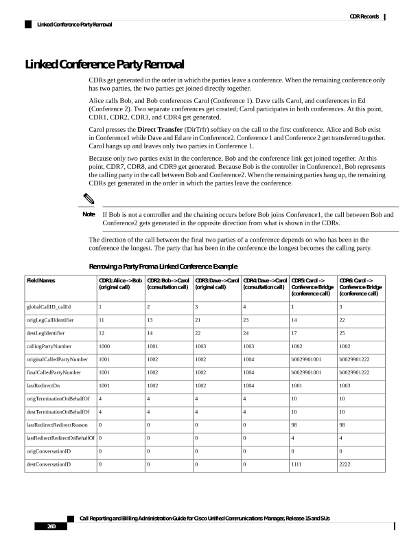
Page 273
CDR6: Carol ->
Conference Bridge
(conference call)
CDR5: Carol ->
Conference Bridge
(conference call)
CDR4: Dave -> Carol
(consultation call)
CDR3: Dave -> Carol
(original call)
CDR2: Bob -> Carol
(consultation call)
CDR1: Alice -> Bob
(original call)
Field Names
ConfControll
erDn=1003;Co
nfController
DeviceName=S
EP0003E333FA
D1;ConfReque
storDn-1003;
ConfRequesto
rDeviceName=
SEP0003E333F
AD1
ConfControll
erDn=1001;Co
nfController
DeviceName=S
EP0003E333FE
BD;ConfReque
storDn-1001;
ConfRequesto
rDeviceName=
SEP0003E333F
EBD
Comment
CDR12: Ed ->
Conference Bridge
(conference call)
CDR11: Dave ->
Conference Bridge
(conference call)
CDR10: Bob ->
Conference Bridge
(conference call)
CDR9: Conference
Bridge ->
Conference Bridge
CDR8: Bob ->
Conference Bridge
(conference call)
CDR7: Alice ->
Conference Bridge
(conference call)
Field Names
3
3
3
3
1
1
globalCallID_callId
24
12
11
25
12
11
origLegCallIdentifier
27
16
15
28
16
15
destLegIdentifier
1003
1001
1000
b0029901222
1001
1001
callingPartyNumber
b0029901222
b0029901222
b0029901222
b0029901001
b0029901001
b0029901001
originalCalledPartyNumber
b0029901222
b0029901222
b0029901222
b0029901001
b0029901001
b0029901001
finalCalledPartyNumber
1003
1003
b0029901001
1002
1001
1001
lastRedirectDn
0
0
4
4
4
16
origTerminationOnBehalfOf
0
0
4
4
4
0
destTerminationOnBehalfOf
98
98
98
4
98
98
lastRedirectRedirectReason
4
4
4
10
4
4
lastRedirectRedirectOnBehalfOf
0
0
0
2222
0
0
origConversationID
2222
2222
2222
1111
1111
1111
destConversationID
ConfControll
erDn=1003;Co
nfController
DeviceName=S
EP0003E333FA
D1;ConfReque
storDn-1003;
ConfRequesto
rDeviceName=
SEP0003E333F
AD1
ConfControll
erDn=1003;Co
nfController
DeviceName=S
EP0003E333FA
D1;ConfReque
storDn-1003;
ConfRequesto
rDeviceName=
SEP0003E333F
AD1
ConfControll
erDn=1003;Co
nfController
DeviceName=S
EP0003E333FA
D1;ConfReque
storDn-1003;
ConfRequesto
rDeviceName=
SEP0003E333F
AD1
ConfControll
erDn=1003;Co
nfController
DeviceName=S
EP0003E333FA
D1;ConfReque
storDn-1003;
ConfRequesto
rDeviceName=
SEP0003E333F
AD1
ConfControll
erDn=1001;Co
nfController
DeviceName=S
EP0003E333FE
BD;ConfReque
storDn-1001;
ConfRequesto
rDeviceName=
SEP0003E333F
EBD
ConfControll
erDn=1001;Co
nfController
DeviceName=S
EP0003E333FE
BD;ConfReque
storDn-1001;
ConfRequesto
rDeviceName=
SEP0003E333F
EBD
Comment
Call Reporting and Billing Administration Guide for Cisco Unified Communications Manager, Release 15 and SUs
261
CDR Records
Linked Conference Party Removal
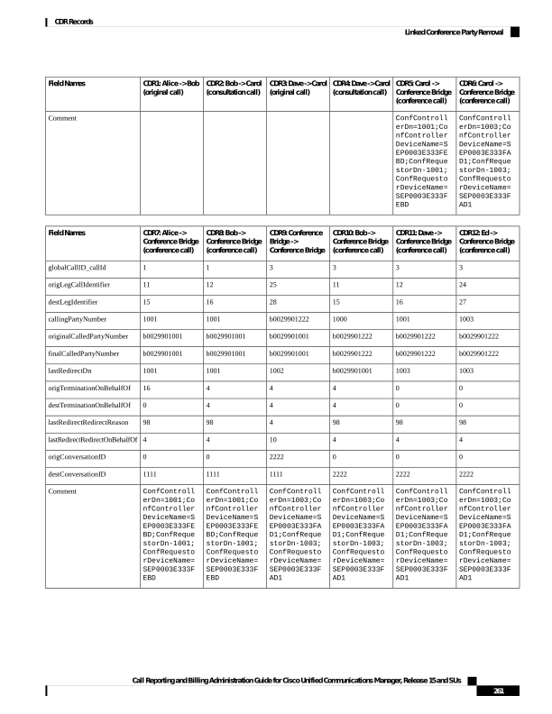
Page 274
Linked Conference Party (Controller) Removal
CDRs get generated in the order in which the parties leave a conference. When the remaining conference only
has two parties, these two parties get joined directly together.
Alice calls Bob, and Bob conferences Carol (Conference 1). Dave calls Carol and conferences in Ed (Conference
2). Two separate conferences get created; Carol participates in both conferences. At this point, CDR1, CDR2,
CDR3, and CDR4 get generated.
Carol presses the Direct Transfer (DirTrfr) softkey on the call to the first conference. Alice and Bob exist
in Conference1, while Dave and Ed are in Conference2. Conference 1 and Conference 2 get transferred
together. Bob hangs up which leaves only two parties that are connected to Conference1.
Because only two parties exist in Conference1, Alice and the conference link get joined directly together. At
this point, CDR7, CDR8, and CDR9 get generated. Because Alice has been in the conference longer, she
becomes the calling party in the call between Alice and Conference2. When the remaining parties hang up,
the remaining CDRs get generated in the order in which the parties leave the conference.
The direction of a call between the final two parties of a conference depends on who has been in the conference
the longest. The party that has been in the conference the longest becomes the calling party.
Note
Removing a Controller From a Linked Conference Example
CDR6: Carol ->
Conference Bridge
(conference call)
CDR5: Carol ->
Conference Bridge
(conference call)
CDR4: Dave -> Carol
(consultation call)
CDR3: Dave -> Carol
(original call)
CDR2: Bob -> Carol
(consultation call)
CDR1: Alice -> Bob
(original call)
Field Names
3
1
4
3
2
1
globalCallID_callId
22
14
23
21
13
11
origLegCallIdentifier
25
17
24
22
14
12
destLegIdentifier
1002
1002
1003
1003
1001
1000
callingPartyNumber
b0029901222
b0029901001
1004
1002
1002
1001
originalCalledPartyNumber
b0029901222
b0029901001
1004
1002
1002
1001
finalCalledPartyNumber
1003
1001
1004
1002
1002
1001
lastRedirectDn
10
10
4
4
4
4
origTerminationOnBehalfOf
10
10
4
4
4
4
destTerminationOnBehalfOf
98
98
0
0
0
0
lastRedirectRedirectReason
4
4
0
0
0
0
lastRedirectRedirectOnBehalfOf
0
0
0
0
0
0
origConversationID
2222
1111
0
0
0
0
destConversationID
Call Reporting and Billing Administration Guide for Cisco Unified Communications Manager, Release 15 and SUs
262
CDR Records
Linked Conference Party (Controller) Removal

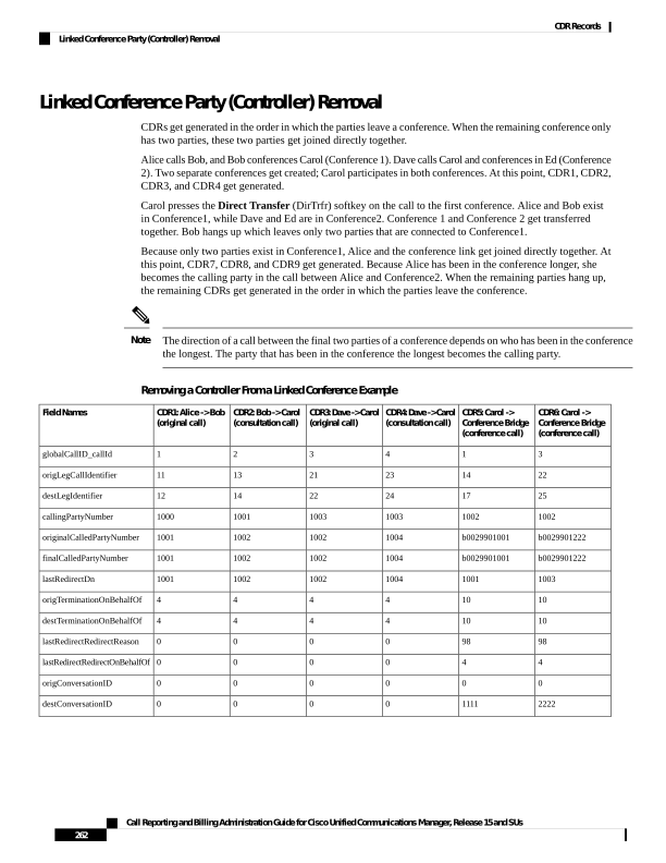
Page 275
CDR6: Carol ->
Conference Bridge
(conference call)
CDR5: Carol ->
Conference Bridge
(conference call)
CDR4: Dave -> Carol
(consultation call)
CDR3: Dave -> Carol
(original call)
CDR2: Bob -> Carol
(consultation call)
CDR1: Alice -> Bob
(original call)
Field Names
ConfControll
erDn=1003;Co
nfController
DeviceName=S
EP0003E333FA
D1;ConfReque
storDn-1003;
ConfRequesto
rDeviceName=
SEP0003E333F
AD1
ConfControll
erDn=1001;Co
nfController
DeviceName=S
EP0003E333FE
BD;ConfReque
storDn-1001;
ConfRequesto
rDeviceName=
SEP0003E333F
EBD
Comment
CDR12: Ed ->
Conference Bridge
(conference call)
CDR11: Dave ->
Conference Bridge
(conference call)
CDR10: Alice ->
Conference Bridge
(conference call)
CDR9: Conference
Bridge ->
Conference Bridge
CDR8: Alice ->
Conference Bridge
(conference call)
CDR7: Conference
Bridge ->
Conference Bridge
Field Names
3
3
3
3
1
1
globalCallID_callId
24
21
11
25
11
12
origLegCallIdentifier
27
26
25
28
15
16
destLegIdentifier
1004
1003
1001
b0029901001
1000
1001
callingPartyNumber
b0029901222
b0029901222
b0029901222
b0029901001
b0029901001
b0029901001
originalCalledPartyNumber
b0029901222
b0029901222
b0029901222
b0029901001
b0029901001
b0029901001
finalCalledPartyNumber
1003
1003
b0029901001
1002
1001
1001
lastRedirectDn
0
0
4
4
16
4
origTerminationOnBehalfOf
0
0
4
4
0
4
destTerminationOnBehalfOf
98
98
98
4
98
98
lastRedirectRedirectReason
4
4
4
10
4
4
lastRedirectRedirectOnBehalfOf
0
0
0
2222
0
0
origConversationID
2222
2222
2222
1111
1111
1111
destConversationID
ConfControll
erDn=1003;Co
nfController
DeviceName=S
EP0003E333FA
D1;ConfReque
storDn-1003;
ConfRequesto
rDeviceName=
SEP0003E333F
AD1
ConfControll
erDn=1003;Co
nfController
DeviceName=S
EP0003E333FA
D1;ConfReque
storDn-1003;
ConfRequesto
rDeviceName=
SEP0003E333F
AD1
ConfControll
erDn=1003;Co
nfController
DeviceName=S
EP0003E333FA
D1;ConfReque
storDn-1003;
ConfRequesto
rDeviceName=
SEP0003E333F
AD1
ConfControll
erDn=1003;Co
nfController
DeviceName=S
EP0003E333FA
D1;ConfReque
storDn-1003;
ConfRequesto
rDeviceName=
SEP0003E333F
AD1
ConfControll
erDn=1001;Co
nfController
DeviceName=S
EP0003E333FE
BD;ConfReque
storDn-1001;
ConfRequesto
rDeviceName=
SEP0003E333F
EBD
ConfControll
erDn=1001;Co
nfController
DeviceName=S
EP0003E333FE
BD;ConfReque
storDn-1001;
ConfRequesto
rDeviceName=
SEP0003E333F
EBD
Comment
Call Reporting and Billing Administration Guide for Cisco Unified Communications Manager, Release 15 and SUs
263
CDR Records
Linked Conference Party (Controller) Removal
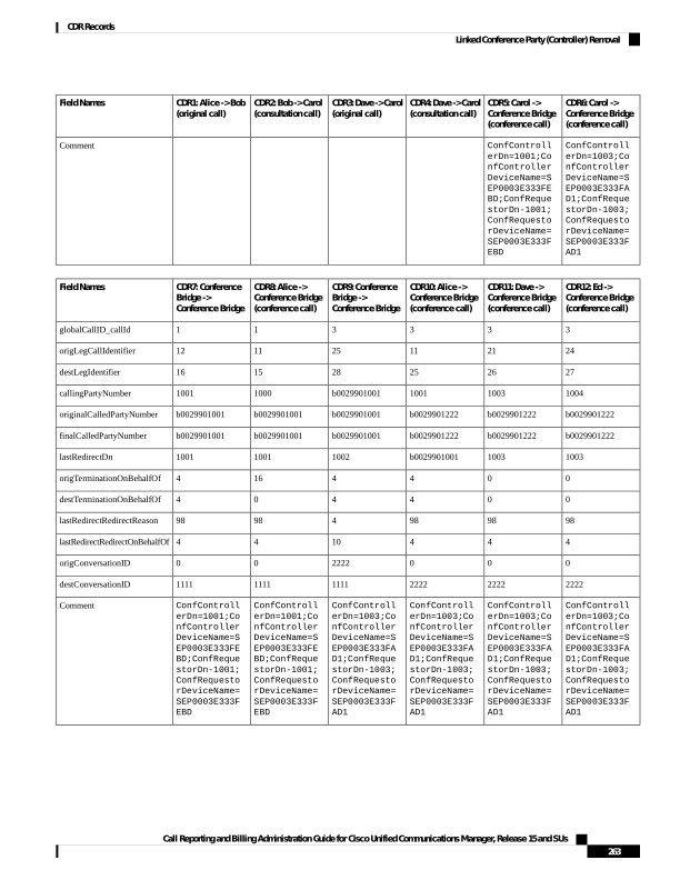
Page 276
Linked Conference Removal
Alice calls Bob, and Bob conferences Carol (Conference 1). Dave calls Carol, and conferences in Ed
(Conference 2). Two separate conferences get created; Carol participates in both conferences. At this point,
CDR1, CDR2, CDR3, and CDR4 get generated.
Carol presses the Direct Transfer (DirTrfr) softkey on the call to the first conference. Alice and Bob exist
in Conference1, while Dave and Ed are in Conference2. Conference 1 and Conference 2 get transferred
together.
Bob presses the ConfList softkey and has Alice, Bob, and the conference link “Conference” shown in the list.
Bob selects “Conference” and presses the Remove softkey. At this point, CDR7, CDR8, and CDR9 get
generated. The conference link gets removed, which leaves two parties in the conference.
The remaining two parties get joined together. In Conference 1, Alice and Bob get joined together, and in
Conference2, Dave and Ed get joined together. When the remaining parties hang up, the remaining CDRs get
generated in the order in which the parties leave the conference.
Removing the Linked Conference Example
CDR6: Carol ->
Conference Bridge
(conference call)
CDR5: Carol ->
Conference Bridge
(conference call)
CDR4: Dave -> Carol
(consultation call)
CDR3: Dave -> Carol
(original call)
CDR2: Bob -> Carol
(consultation call)
CDR1: Alice -> Bob
(original call)
Field Names
3
1
4
3
2
1
globalCallID_callId
22
14
23
21
13
11
origLegCallIdentifier
25
17
24
22
14
12
destLegIdentifier
1002
1002
1003
1003
1001
1000
callingPartyNumber
b0029901222
b0029901001
1004
1002
1002
1001
originalCalledPartyNumber
b0029901222
b0029901001
1004
1002
1002
1001
finalCalledPartyNumber
1003
1001
1004
1002
1002
1001
lastRedirectDn
10
10
4
4
4
4
origTerminationOnBehalfOf
10
10
4
4
4
4
destTerminationOnBehalfOf
98
98
0
0
0
0
lastRedirectRedirectReason
4
4
0
0
0
0
lastRedirectRedirectOnBehalfOf
0
0
0
0
0
0
origConversationID
2222
1111
0
0
0
0
destConversationID
ConfControll
erDn=1003;Co
nfController
DeviceName=S
EP0003E333FA
D1;ConfReque
storDn-1003;
ConfRequesto
rDeviceName=
SEP0003E333F
AD1
ConfControll
erDn=1001;Co
nfController
DeviceName=S
EP0003E333FE
BD;ConfReque
storDn-1001;
ConfRequesto
rDeviceName=
SEP0003E333F
EBD
Comment
Call Reporting and Billing Administration Guide for Cisco Unified Communications Manager, Release 15 and SUs
264
CDR Records
Linked Conference Removal
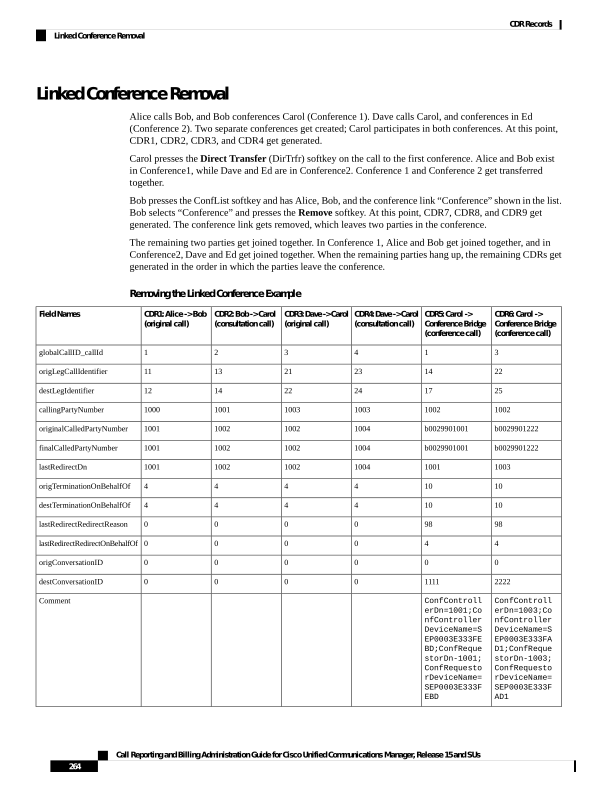
Page 277
CDR12: Bob-> Alice
CDR11: Ed ->
Conference Bridge
(conference call)
CDR10: Dave ->
Conference Bridge
(conference call)
CDR9: Bob ->
Conference Bridge
CDR8: Alice ->
Conference Bridge
(conference call)
CDR7: Conference
Bridge ->
Conference Bridge
Field Names
3
3
3
1
1
3
globalCallID_callId
21
24
21
12
11
25
origLegCallIdentifier
24
27
26
16
15
28
destLegIdentifier
1003
1004
1003
1001
1000
b0029901222
callingPartyNumber
b0029901222
b0029901222
b0029901222
b0029901001
b0029901001
b0029901001
originalCalledPartyNumber
1004
b0029901222
b0029901222
b0029901001
b0029901001
b0029901001
finalCalledPartyNumber
b0029901222
1003
1003
1001
1001
1002
lastRedirectDn
0
0
16
4
4
4
origTerminationOnBehalfOf
0
0
0
4
4
4
destTerminationOnBehalfOf
98
98
98
98
98
4
lastRedirectRedirectReason
4
4
4
4
4
10
lastRedirectRedirectOnBehalfOf
0
0
0
0
0
0
origConversationID
0
2222
2222
1111
1111
1111
destConversationID
ConfControll
erDn=1003;Co
nfController
DeviceName=S
EP0003E333FA
D1;ConfReque
storDn-1003;
ConfRequesto
rDeviceName=
SEP0003E333F
AD1
ConfControll
erDn=1003;Co
nfController
DeviceName=S
EP0003E333FA
D1;ConfReque
storDn-1003;
ConfRequesto
rDeviceName=
SEP0003E333F
AD1
ConfControll
erDn=1003;Co
nfController
DeviceName=S
EP0003E333FA
D1;ConfReque
storDn-1003;
ConfRequesto
rDeviceName=
SEP0003E333F
AD1
ConfControll
erDn=1001;Co
nfController
DeviceName=S
EP0003E333FE
BD;ConfReque
storDn-1001;
ConfRequesto
rDeviceName=
SEP0003E333F
EBD
ConfControll
erDn=1001;Co
nfController
DeviceName=S
EP0003E333FE
BD;ConfReque
storDn-1001;
ConfRequesto
rDeviceName=
SEP0003E333F
EBD
ConfControll
erDn=1003;Co
nfController
DeviceName=S
EP0003E333FA
D1;ConfReque
storDn-1003;
ConfRequesto
rDeviceName=
SEP0003E333F
AD1
Comment
CDR13: Dave -> Ed
Field Names
3
globalCallID_callId
21
origLegCallIdentifier
24
destLegIdentifier
1003
callingPartyNumber
b0029901222
originalCalledPartyNumber
1004
finalCalledPartyNumber
b0029901222
lastRedirectDn
0
origTerminationOnBehalfOf
Call Reporting and Billing Administration Guide for Cisco Unified Communications Manager, Release 15 and SUs
265
CDR Records
Linked Conference Removal
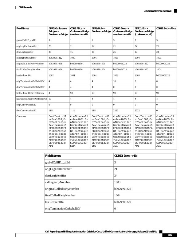
Page 278
CDR13: Dave -> Ed
Field Names
0
destTerminationOnBehalfOf
98
lastRedirectRedirectReason
4
lastRedirectRedirectOnBehalfOf
0
origConversationID
0
destConversationID
ConfControllerDn=10
03;ConfControllerDe
viceName=SEP0003E33
3FAD1;ConfRequestor
Dn-1003;ConfRequest
orDeviceName=SEP000
3E333FAD1
Comment
Agent Greeting Calls
The Agent Greeting call feature instructs Unified Communications Manager to play a prerecorded announcement
to the customer automatically after successful media connection to the agent device occurs. Both the agent
and the customer hear the Agent Greeting.
Example of an Agent Greeting Call
1.
The customer (1001) calls the agent (1006).
2.
The agent (1006) answers the call. The customer and the agent connect.
3.
The Agent Greeting call feature instructs Unified Communications Manager to play a prerecorded
announcement to the customer automatically after successful media connection to the agent device occurs.
This causes an IVR (1000) to connect to the Built-In Bridge (BIB) of agent phone. Both the agent and
the customer hear the Agent Greeting.
4.
The customer-agent call ends. A CDR gets generated for the customer-to-agent call. A CDR gets generated
for the IVR (1000) to BIB of agent phone.
The CDR for the IVR to agent BIB specifies the comment AgentGreeting=<agentCI>. The OnBehalfOf
field is set to 33 and redirectReason code is set to 752 for Agent Greeting call.
Call From IVR to Agent BIB
Call From Customer to Agent
Field Names
270002
270001
globalCallID_callId
22980861
22980857
origLegCallIdentifier
22980862
22980858
destLegIdentifier
1000
1001
callingPartyNumber
b00121104001
1006
originalCalledPartyNumber
Call Reporting and Billing Administration Guide for Cisco Unified Communications Manager, Release 15 and SUs
266
CDR Records
Agent Greeting Calls
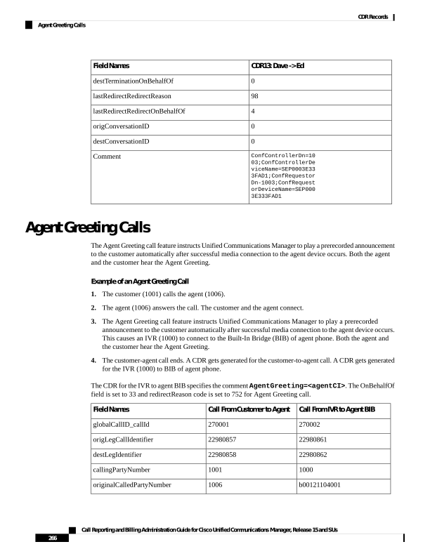
Page 279
Call From IVR to Agent BIB
Call From Customer to Agent
Field Names
b00121104001
1006
finalCalledPartyNumber
0
12
origCallTerminationOnBehalfOf
33
0
destCallTerminationOnBehalfOf
33
0
origCalledPartyRedirectOnBehalfOf
33
0
lastRedirectRedirectOnBehalfOf
752
0
origCalledPartyRedirectReason
752
0
lastRedirectRedirectReason
22980858
0
destConversationId
33
joinOnBehalfOf
AgentGreeting=22980858
comment
9
23
duration
Barge
When a shared line uses the barge feature, the origCalledPartyNumber, finalCalledPartyNumber, and
lastRedirectDn represent the conference bridge number 'b00. . .'. The redirect and join OnBehalfOf fields
reflect a value of Barge = 15, and the redirect reason fields specify Barge = 114.
Barge Examples
1.
40003 calls 40001, and 40001 answers. Shared line 40001' on another phone presses the Barge softkey.
All the parties get conferenced together; then, 40003 hangs up.
Both CDRs have the same globalCallID_callId, and the conversationID field links back to the CI (call Identifier)
of the barged call.
Note
Barge Call CDR
Original Call CDR
Field Names
7
7
globalCallID_callId
16777232
16777230
origLegCallIdentifier
16777235
16777231
destLegIdentifier
40003
40003
callingPartyNumber
b001501001
40001
origCalledPartyNumber
b001501001
40001
finalCalledPartyNumber
Call Reporting and Billing Administration Guide for Cisco Unified Communications Manager, Release 15 and SUs
267
CDR Records
Barge

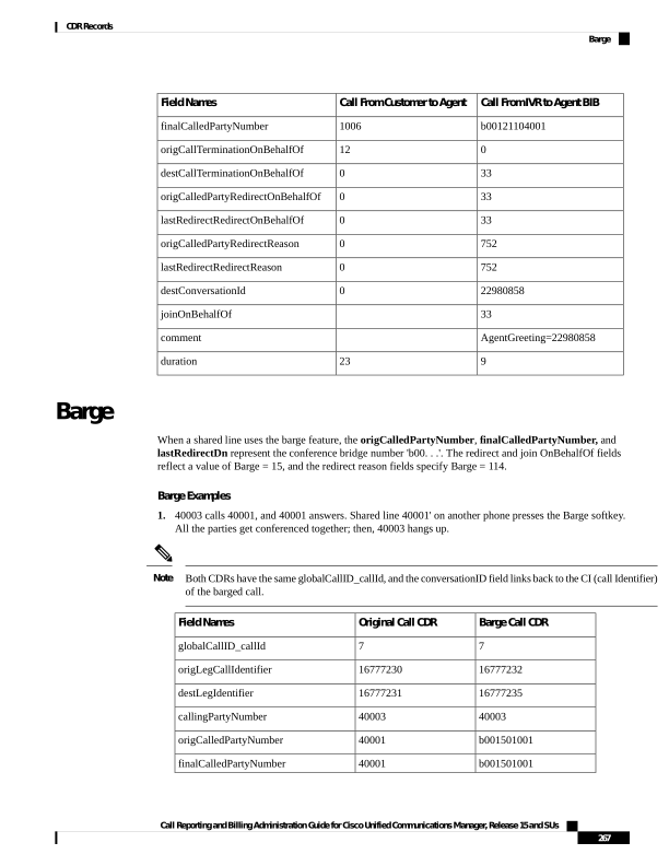
Page 280
Barge Call CDR
Original Call CDR
Field Names
b001501001
40001
lastRedirectDn
0
16
origCause_Value
0
0
dest_CauseValue
114
0
origCalledPartyRedirectReason
114
0
lastRedirectRedirectReason
15
origCalledPartyRedirectOnBehalfOf
15
lastRedirectRedirectOnBehalfOf
15
joinOnBehalfOf
16777231
0
destConversationID
2.
40003 calls 40001, and 40001 answers. Shared line 40001' on another phone presses the Barge softkey.
All the parties get conferenced together; then, 40001 hangs up.
Both CDRs have the same globalCallID_callId, and the conversationID field links back to the CI (call Identifier)
of the barged call.
Note
Final Call 2 CDR
Barge Call 1 CDR
Original Call CDR
Field Names
9
9
9
globalCallID_callId
16777236
16777238
16777236
origLegCallIdentifier
16777238
16777241
16777237
destLegIdentifier
40003
40001
40003
callingPartyNumber
40001
b001501001
40001
origCalledPartyNumber
40001
b001501001
40001
finalCalledPartyNumber
40001
b001501001
40001
lastRedirectDn
16
393216
0
origCause_Value
0
393216
16
dest_CauseValue
0
114
0
origCalledPartyRedirectReason
0
114
0
lastRedirectRedirectReason
12
15
origTerminationOnBehalfOf
12
15
12
destTerminationOnBehalfOf
15
lastRedirectRedirectOnBehalfOf
Call Reporting and Billing Administration Guide for Cisco Unified Communications Manager, Release 15 and SUs
268
CDR Records
Barge

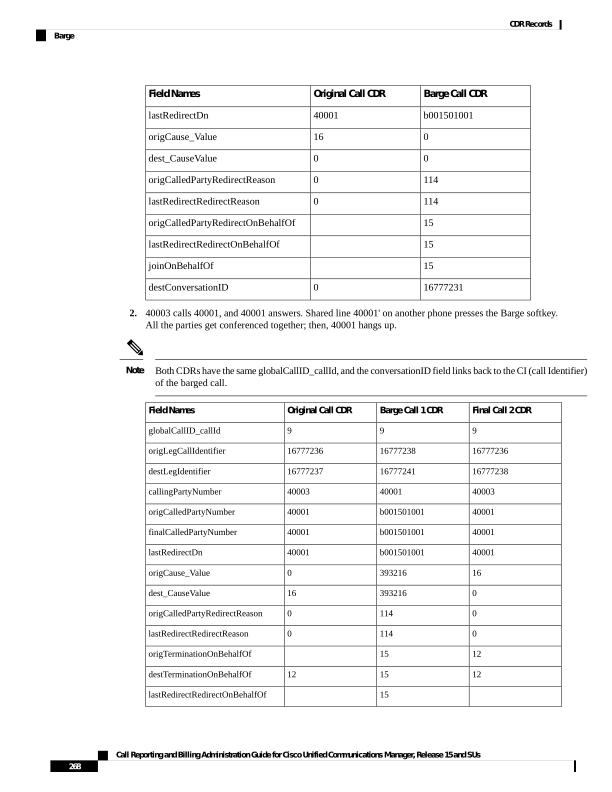
Page 281
Final Call 2 CDR
Barge Call 1 CDR
Original Call CDR
Field Names
15
joinOnBehalfOf
0
16777237
0
destConversationID
3.
40003 calls 40001, and 40001 answers. Shared line 40001' on another phone presses the Barge softkey.
All the parties get conferenced together; then, 40001' (another shared line and phone) presses the Barge
softkey. 40003 hangs up first.
All CDRs have the same globalCallID_callId, and the conversationID field links back to the CI (call Identifier)
of the barged call.
Note
Final Call 2 CDR
Barge Call 1 CDR
Original Call CDR
Field Names
14
14
14
globalCallID_callId
16777255
16777251
16777249
origLegCallIdentifier
16777258
16777254
16777250
destLegIdentifier
40001
40001
40003
callingPartyNumber
b001501001
b001501001
40001
origCalledPartyNumber
b001501001
b001501001
40001
finalCalledPartyNumber
b001501001
b001501001
40001
lastRedirectDn
0
0
16
origCause_Value
0
0
0
dest_CauseValue
114
114
0
origCalledPartyRedirectReason
114
114
0
lastRedirectRedirectReason
15
15
12
origTerminationOnBehalfOf
destTerminationOnBehalfOf
15
15
origRedirectRedirectOnBehalfOf
15
15
lastRedirectRedirectOnBehalfOf
15
15
joinOnBehalfOf
16777251
16777250
0
destConversationID
Call Monitoring
The system generates CDRs for the Call Monitoring feature by using existing CDR fields.
The monitoring calls have one-way media. The media fields stay empty for one side of the call for one-way
media CDRs.
Call Reporting and Billing Administration Guide for Cisco Unified Communications Manager, Release 15 and SUs
269
CDR Records
Call Monitoring

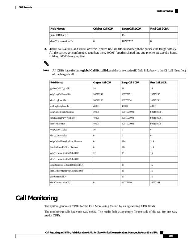
Page 282
The destConversationID field of the Call Monitoring CDR matches the agent call leg identifier in the CDR
of the call that is monitored and links together the Call Monitoring CDR and the CDR of the monitored call.
Call Monitoring Examples
1.
The customer (9728134987) calls the agent (30000), and the agent answers. The supervisor (40003)
monitors the call. The destConversationID from the monitoring call matches the destLegIdentifier of the
monitored call.
Monitoring Call CDR
Monitored Call CDR
Field Names
10
7
globalCallID_callId
16777232
16777230
origLegCallIdentifier
16777235
16777231
destLegIdentifier
40003
9728134987
callingPartyNumber
b001501001
30000
originalCalledPartyNumber
b001501001
30000
finalCalledPartyNumber
b001501001
30000
lastRedirectDn
0
16
origCause_Value
0
0
dest_CauseValue
370
0
origCalledPartyRedirectReason
370
0
lastRedirectRedirectOnBehalfOf
28
origCalledPartyRedirectOnBehalfOf
28
lastRedirectRedirectOnBehalfOf
16777231
0
destConversationID
2.
The agent (30000) calls the customer (9728134987), and the customer answers. The supervisor (40003)
monitors the call. The destConversationID from the monitoring call matches the origLegCallIdentifier of
the monitored call.
Monitoring Call CDR
Monitored Call CDR
Field Names
101
71
globalCallID_callId
16777932
16777299
origLegCallIdentifier
16777235
16777300
destLegIdentifier
40003
30000
callingPartyNumber
b001501002
9728134987
originalCalledPartyNumber
b001501002
9728134987
finalCalledPartyNumber
Call Reporting and Billing Administration Guide for Cisco Unified Communications Manager, Release 15 and SUs
270
CDR Records
Call Monitoring
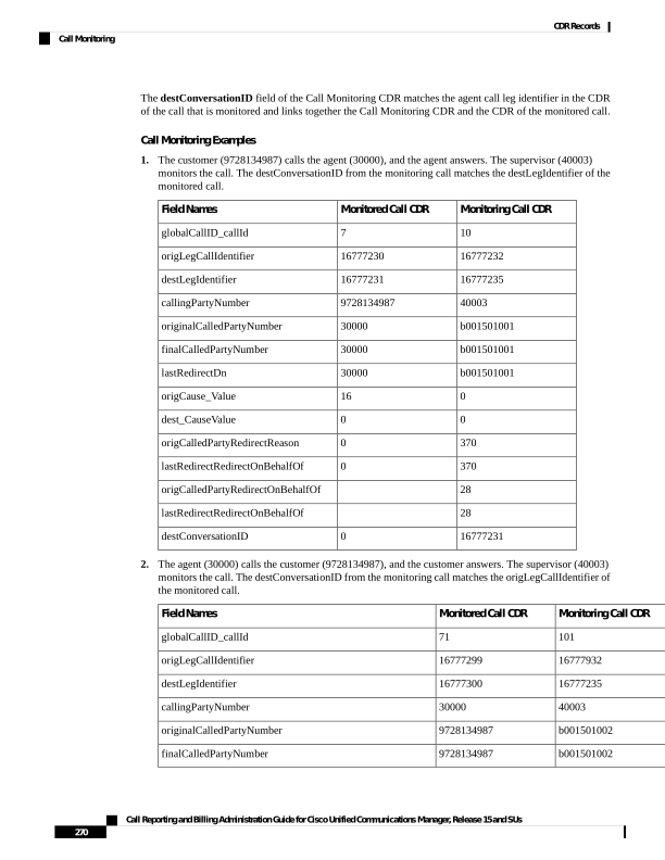
Page 283
Monitoring Call CDR
Monitored Call CDR
Field Names
b001501002
9728134987
lastRedirectDn
0
16
origCause_Value
0
0
dest_CauseValue
370
0
origCalledPartyRedirectReason
370
0
lastRedirectRedirectOnBehalfOf
28
origCalledPartyRedirectOnBehalfOf
28
lastRedirectRedirectOnBehalfOf
16777299
0
destConversationID
Call Park
Call Park generates two CDRs, one for the original call that gets parked and another for the call that gets
picked up or reverted. These CDRs will have the same globalCallID_callId.
Call Park Pickup
When the call is parked, the call gets split. The original call generates a CDR. The
origTerminationOnBehalfOf and destTerminationOnBehalfOf fields get set to Call Park = 3 for this CDR.
When the parked call gets retrieved, the user goes off hook and enters the park code. This call joins with the
parked call. Because the user who is picking up the call gets joined with the parked call, the system treats the
user as the originator of the call, and the parked user gets treated as the destination. This means that the
callingPartyNumber field of the call contains the directory number of the user who is picking up the call,
and the originalCalledNumber and finalCalledNumber fields contain the directory number of the parked
user. The lastRedirectDn field contains the park code that is used to pick up the call. The
lastRedirectRedirectReason field specifies Call Park Pickup = 8. The lastRedirectRedirectOnBehalfOf
field should specify Call Park = 3.
Call Park Pickup CDR Example
50003 calls 50002; 50002 presses the Park softkey. 50001 picks up the parked call by dialing the park code
(44444).
Parked Call That Is Picked Up
CDR
Original Call That Is Parked
CDR
Field Names
1
1
globalCallID_callId
20863961
20863957
origLegCallIdentifier
20863957
20863958
destLegIdentifier
Call Reporting and Billing Administration Guide for Cisco Unified Communications Manager, Release 15 and SUs
271
CDR Records
Call Park
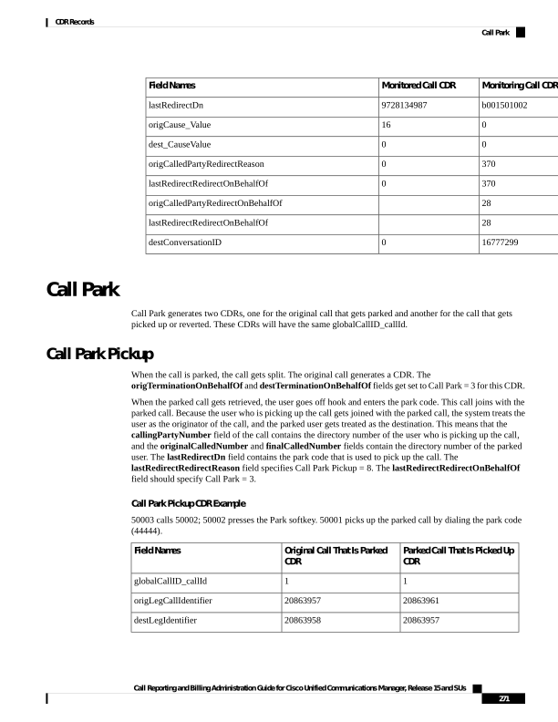
Page 284
Parked Call That Is Picked Up
CDR
Original Call That Is Parked
CDR
Field Names
50001
50003
callingPartyNumber
50003
50002
originalCalledPartyNumber
50003
50002
finalCalledPartyNumber
44444
50002
lastRedirectDn
0
393216
origCause_Value
16
393216
dest_CauseValue
0
0
origCalledPartyRedirectReason
8
0
lastRedirectRedirectReason
0
0
origCalledPartyRedirectOnBehalfOf
3
0
lastRedirectRedirectOnBehalfOf
0
3
origTerminationOnBehalfOf
12
3
destTerminationOnBehalfOf
3
0
joinOnBehalfOf
60
4
duration
Call Park Reversion
When a call is parked and not picked up, the call park reversion timer expires and redirects the call to the
called party. In this case, the system generates two CDRs. The first CDR appears the same as the preceding
Call Park Pickup scenario, but the second CDR differs slightly. When the Call Pickup Reversion timer expires,
the call gets redirected to the called party.
When the call is parked, the call gets split. This action generates a CDR for the original call. The
origTerminationOnBehalfOf and destTerminationOnBehalfOf fields get set to Call Park = 3 for this CDR,
the same as the Call Park Pickup scenario.
When the Call Park Reversion timer expires, the call gets redirected to the called party. The
origCalledPartyRedirectOnBehalfOf and lastRedirectRedirectOnBehalfOf fields specify Call Park = 3.
The origCalledPartyRedirectReason field specifies Call Park = 7, and the lastRedirectRedirectReason
field specifies Call Park Reversion = 11.
Call Park Reversion CDR Example
• Call Park Reversion Example – 50003 calls 50002; 50002 presses the Park softkey. Nobody picks up
the parked call; the parked call reverts to 50002, and 50002 answers.
Call Reporting and Billing Administration Guide for Cisco Unified Communications Manager, Release 15 and SUs
272
CDR Records
Call Park Reversion
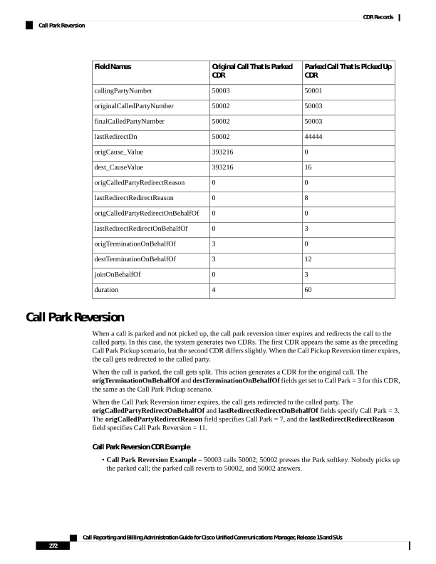
Page 285
Reverted Call CDR
Original Call That Is Parked
CDR
Field Names
2
2
globalCallID_callId
20863963
20863963
origLegCallIdentifier
20863967
20863964
destLegIdentifier
50003
50003
callingPartyNumber
50002
50002
originalCalledPartyNumber
50002
50002
finalCalledPartyNumber
50002
50002
lastRedirectDn
0
393216
origCause_Value
16
393216
dest_CauseValue
7
0
origCalledPartyRedirectReason
11
0
lastRedirectRedirectReason
3
0
origCalledPartyRedirectOnBehalfOf
3
0
lastRedirectRedirectOnBehalfOf
3
3
origTerminationOnBehalfOf
12
3
destTerminationOnBehalfOf
3
0
joinOnBehalfOf
60
7
duration
Call Pickup
There are two types of call pickup in Unified Communications Manager: Pickup and Auto Pickup. The CDR
records appear slightly different for these two types of call pickup.
Pickup
Pickup CDR Example
A call comes in from the PSTN to extensions 2000, 2001, and 2002. These extensions reside in the same
pickup group. Extension 2002 picks up the call that is ringing on 2001. Extension 2002 answers the call, and
the call connects between the PSTN caller and extension 2002.
Call Reporting and Billing Administration Guide for Cisco Unified Communications Manager, Release 15 and SUs
273
CDR Records
Call Pickup

Page 286
Pickup Call CDR
Field Names
22
globalCallID_callId
9728131234
callingPartyNumber
2001
originalCalledPartyNumber
2002
finalCalledPartyNumber
2001
lastRedirectDn
0
origCause_Value
16
dest_CauseValue
16
origTerminationOnBehalfOf
16
destTerminationOnBehalfOf
16
lastRedirectOnBehalfOf
5
lastRedirectReason
16
joinOnBehalfOf
Auto Pickup
Auto Pickup acts like call pickup with auto answer. The user does not need to press the last answer softkey.
The call automatically connects. Two CDRs get generated for Auto Pickup. These CDRs have the same Call
ID.
• The first CDR gets generated for the original call. This CDR has the origTerminationOnBehalfOf and
destTerminationOnBehalfOf fields equal to 16 (Pickup). Thisvalue indicates that the call got terminated
on behalf of the Pickup feature.
• The second CDR represents the final call after it was picked up. This CDR has the
lastRedirectOnBehalfOf and the joinOnBehalfOf fields set to 16 (Pickup). This value indicates that
the call was joined on behalf of the Pickup feature. The lastRedirectReason contains the redirect reason
of 5 (Pickup).
Auto Pickup CDRs look the same for all types of auto pickup: Auto Pickup, Auto Group Pickup and Auto
Other Pickup.
When the Service Parameter Auto Call Pickup Enabled is set to True for an IP Phone and a Unified
Communications Manager receives an incoming call that the IP phone picks up, the prefix digit defined in
the Translation Pattern is added to the callingPartyNumber in CDR. However, the prefix digit is not added
when the Service Parameter Auto Call Pickup Enabled is set to False.
Note
Call Reporting and Billing Administration Guide for Cisco Unified Communications Manager, Release 15 and SUs
274
CDR Records
Auto Pickup

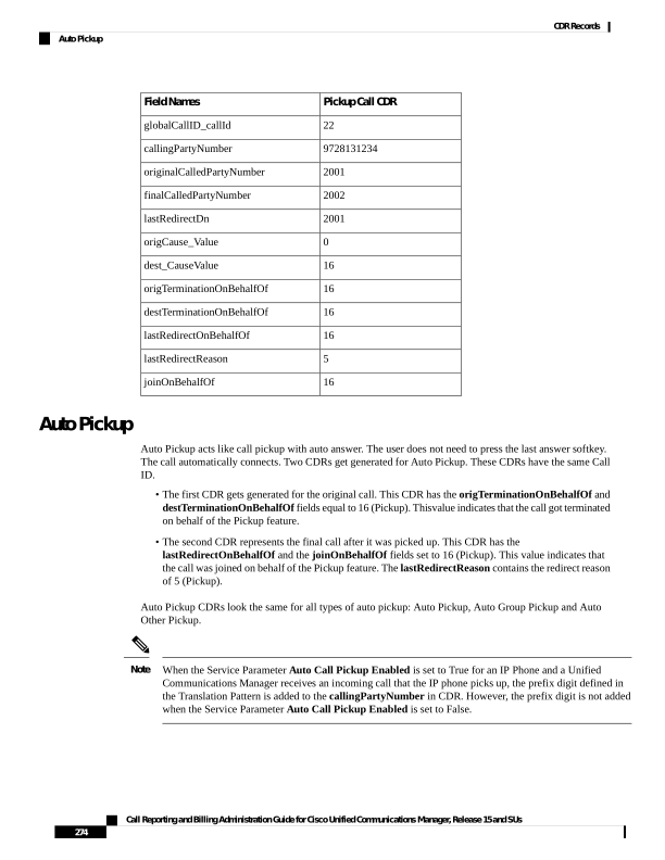
Page 287
Auto Pickup CDR Example
• Auto Pickup Example - Call goes from the PSTN to extension 2001; 2001 and 2002 exist in the same
pickup group. 2002 picks up the call that rings on 2001; the call automatically connects between the
PSTN caller and 2002. They talk for 2 minutes.
The prefix digits defined in the Translation Pattern only applies to basic call.
Note
Pickup CDR
Original Call CDR
Field Names
11
11
globalCallID_callId
12345
12345
origLegCallIdentifier
12347
12346
destLegIdentifier
9728134987
9728134987
callingPartyNumber
2001
2001
originalCalledPartyNumber
2002
2001
finalCalledPartyNumber
2001
2001
lastRedirectDn
16
393216
origCause_Value
0
393216
dest_CauseValue
12
16
origTerminationOnBehalfOf
16
16
destTerminationOnBehalfOf
5
0
lastRedirectRedirectReason
16
0
lastRedirectRedirectOnBehalfOf
16
0
joinOnBehalfOf
120
0
duration
Call Recording
The system generates CDRs for the Call Recording feature by using existing CDR fields.
The recording calls have one-way media. The media fields stay empty for one side of the call for one-way
media CDRs.
The origConversationID field of the two Call Recording CDRs matches the agent call leg identifier in the
Recording Call CDR and links together the Call Recording CDR and the CDR of the recorded call.
Call Reporting and Billing Administration Guide for Cisco Unified Communications Manager, Release 15 and SUs
275
CDR Records
Call Recording

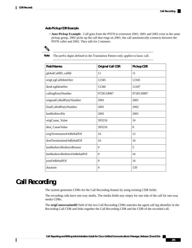
Page 288
If the CDR Log Calls with Zero Duration Flag service parameter is set to true, two additional server call
records are created.
Note
Call Recording CDR Examples
1.
The customer (9728134987) calls the agent (30000), and the agent answers. The Recorder's DN is 90000.
The recording feature creates two recording calls to the recording device, which results in two additional
CDRs: one for the agent voice, and another for the customer voice. The origConversationID from the
recording CDRs matches the destLegIdentifier of the recorded CDR. In this scenario, the customer hangs
up.
Recording Call CDR2
Recording Call CDR1
Recorded Call CDR
Field Names
11
10
7
globalCallID_callId
16777122
16777120
16777110
origLegCallIdentifier
16777123
16777121
16777111
destLegIdentifier
BIB
BIB
9728134987
callingPartyNumber
90000
90000
30000
originalCalledPartyNumber
90000
90000
30000
finalCalledPartyNumber
90000
90000
30000
lastRedirectDn
0
0
16
origCause_Value
0
0
0
dest_CauseValue
354
354
0
origCalledPartyRedirectReason
354
354
0
lastRedirectRedirectOnBehalfOf
27
27
origCalledPartyRedirectOnBehalfOf
27
27
lastRedirectRedirectOnBehalfOf
16777111
16777111
0
origConversationID
2.
The agent (30000) calls the customer (9728134987), and the customer answers. The Recorder's DN is
90000. The recording feature creates two recording calls to the recording device, which results in two
additional CDRs: one for the agent voice, and another for the customer voice. The origConversationID
field from the recording CDRs will match the origLegCallIdentifier field of the recorded CDR. In this
scenario, the agent hangs up.
Recording Call CDR 2
Recording Call CDR 1
Recorded Call CDR
Field Names
110
100
71
globalCallID_callId
16777222
16777220
16777113
origLegCallIdentifier
16777223
16777221
16777114
destLegIdentifier
BIB
BIB
30000
callingPartyNumber
Call Reporting and Billing Administration Guide for Cisco Unified Communications Manager, Release 15 and SUs
276
CDR Records
Call Recording

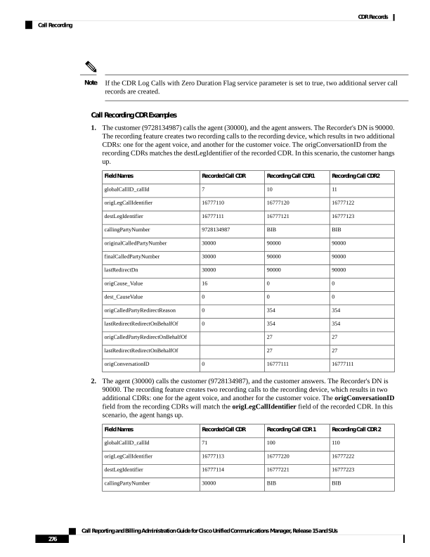
Page 289
Recording Call CDR 2
Recording Call CDR 1
Recorded Call CDR
Field Names
90000
90000
9728134987
originalCalledPartyNumber
90000
90000
9728134987
finalCalledPartyNumber
90000
90000
9728134987
lastRedirectDn
16
16
16
origCause_Value
0
0
0
dest_CauseValue
354
354
0
origCalledPartyRedirectReason
354
354
0
lastRedirectRedirectOnBehalfOf
27
27
origCalledPartyRedirectOnBehalfOf
27
27
lastRedirectRedirectOnBehalfOf
16777113
16777113
0
origConversationID
Call Secured Status
This field identifies security status of the call. It contains the highest level of security that is reached during
a call. For example, if the call is originally unsecured, and later the call changes to secured, the CDR contains
1 for “Secured” even though different portions of the call have different status values. The callSecuredStatus
field identifies the security status of the call.
Call Secured Status CDR Examples
1.
Encrypted Call - The system encrypts the call between 20000 and 20001. The parties talk for 5minutes.
CDR
Field Names
102
globalCallID_callId
16777140
origLegCallIdentifier
16777141
destLegIdentifier
20000
callingPartyNumber
20001
origCalledPartyNumber
20001
finalCalledPartyNumber
20001
lastRedirectDn
0
origCause_Value
16
dest_CauseValue
2
callSecuredStatus
300
duration
Call Reporting and Billing Administration Guide for Cisco Unified Communications Manager, Release 15 and SUs
277
CDR Records
Call Secured Status
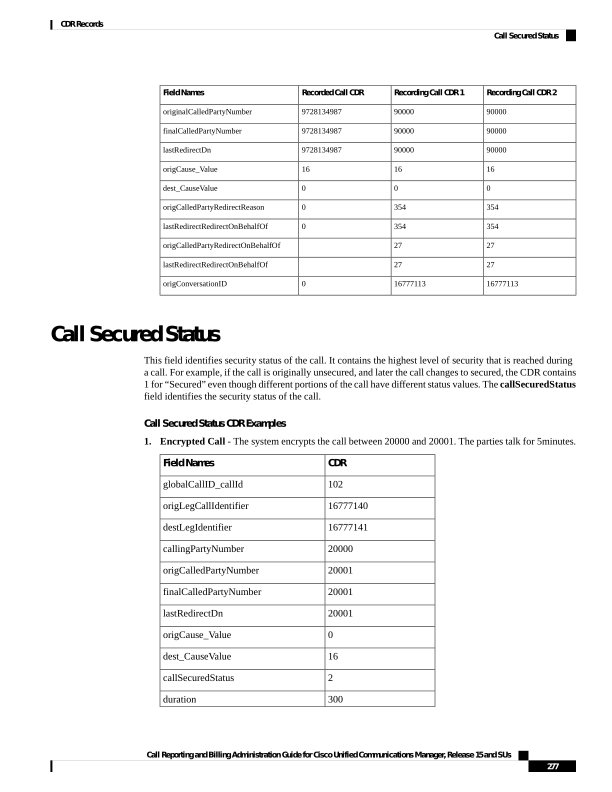
Page 290
Authenticated Call - The call between 20000 and 20001 gets authenticated (not encrypted). The parties
talk for 10 minutes.
CDR
Field Names
103
globalCallID_callId
16777142
origLegCallIdentifier
16777143
destLegIdentifier
20000
callingPartyNumber
20001
origCalledPartyNumber
20001
finalCalledPartyNumber
20001
lastRedirectDn
0
origCause_Value
16
dest_CauseValue
1
callSecuredStatus
600
duration
Calling Party Normalization
This feature provides the support of the international escape code "+" to Unified Communications Manager.
This addition enhances the dialing capabilities of dual-mode phones and improves callbacks for companies
in different geographical locations.
The callingPartyNumber, originalCalledPartyNumber, finalCalledPartyNumber, lastRedirectDN fields,
and the new fields, outpulsedCallingPartyNumber and outpulsedCalledPartyNumber, may now contain
a "+" in the CDR. The device reports the Calling Party Number that it outpulsed back to Call Control only if
calling party normalization/localization takes place. If calling party normalization/localization occurs, the
action gets recorded in the CDR in the new field outpulsedCallingPartyNumber.
Calling Party Normalization CDR Examples
1.
A call gets placed from a Dallas PSTN to an enterprise phone. The 7-digit calling number comprises
5001212; the Dallas area code displays 972. The calling party transformation contains +1972. The
callingPartyNumber field in the CDR contains +1 972 500 1212 (global format). The new field
outpulsedCallingPartyNumber contains the localized number 500 1212.
Values
Field Names
1
globalCallID_callId
100
origLegCallIdentifier
101
destLegIdentifier
Call Reporting and Billing Administration Guide for Cisco Unified Communications Manager, Release 15 and SUs
278
CDR Records
Calling Party Normalization
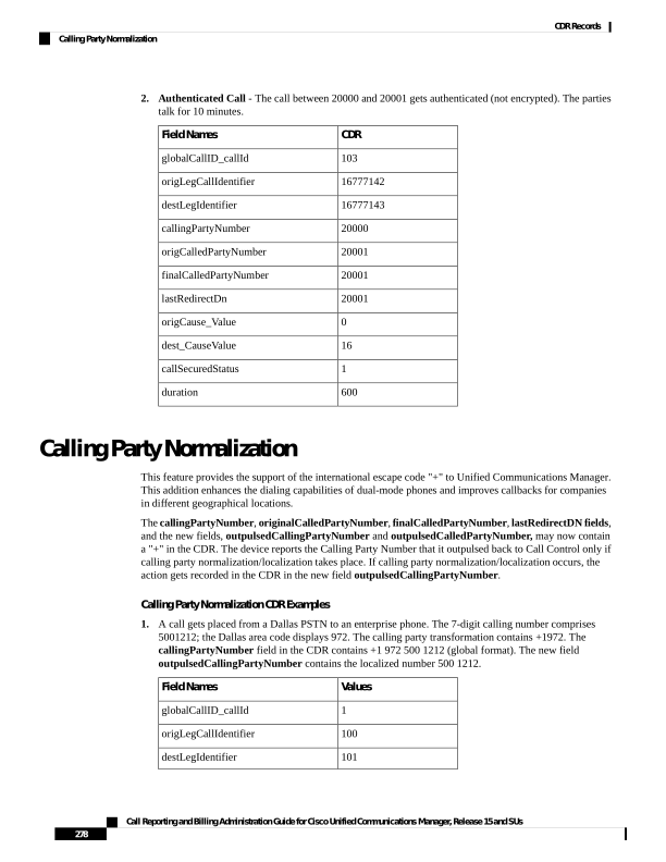
Page 291
Values
Field Names
+19725001212
callingPartyNumber
5001212
outpulsedCallingPartyNumber
60
duration
1.
A call gets placed from an enterprise phone to a Dallas PSTN. The extension of the enterprise phone
comprises 12345; the fully qualified number comprises 9725002345. Calling party transformation checks
the external phone number mask feature. The callingPartyNumber field in the CDR contains +1 972
500 2345 (global format). The new field outpulsedCallingPartyNumber contains the localized number
9725002345.
Values
Field Names
2
globalCallID_callId
102
origLegCallIdentifier
103
destLegIdentifier
+19725002345
callingPartyNumber
9725002345
outpulsedCallingPartyNumber
60
duration
Calls with Busy or Bad Destinations
The system logs all these calls as normal calls, and all relevant fields contain data. The Calling or Called Party
Cause fields contain a cause code that indicates why the call does not connect, and the Called Party IP and
Date/Time Connect fields remain blank. The system logs all unsuccessful calls, even if zero duration calls
are not being logged (CdrLogCallsWithZeroDurationFlag set at True or False, a duration of zero, and a
DateTimeConnect value of zero).
Examples of Unsuccessful Calls CDRs
1.
Call goes to PSTN number, but party already is engaged (cause 17 = user busy)
CDR
Field Names
3
globalCallID_callId
300
origLegCallIdentifier
301
destLegIdentifier
2001
callingPartyNumber
9728134987
originalCalledPartyNumber
Call Reporting and Billing Administration Guide for Cisco Unified Communications Manager, Release 15 and SUs
279
CDR Records
Calls with Busy or Bad Destinations
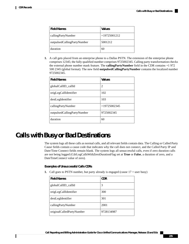
Page 292
CDR
Field Names
0
origCause_Value
17
dest_CauseValue
0
duration
2.
Call goes to PSTN number, but number does not exist (cause 1 = number unavailable)
CDR
Field Names
4
globalCallID_callId
302
origLegCallIdentifier
303
destLegIdentifier
2001
callingPartyNumber
9728134987
originalCalledPartyNumber
1
origCause_Value
0
dest_CauseValue
0
duration
3.
Call to PSTN fails because PSTN trunks are out of order (cause 38 = Network Out Of Order).
CDR
Field Names
5
globalCallID_callId
304
origLegCallIdentifier
305
destLegIdentifier
2001
callingPartyNumber
9728134987
originalCalledPartyNumber
0
origCause_Value
38
dest_CauseValue
0
duration
cBarge
The cBarge feature acts very similar to the conference feature. When a shared line uses the cBarge feature,
the origCalledPartyNumber, finalCalledPartyNumber and lastRedirectDn represent the conference bridge
Call Reporting and Billing Administration Guide for Cisco Unified Communications Manager, Release 15 and SUs
280
CDR Records
cBarge
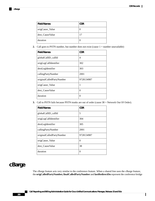
Page 293
number 'b00. . . '. The redirect and join OnBehalfOf fields have a value of Conference = 4, and the redirect
reason fields specify Conference = 98.
cBarge CDR Example
40003 calls 40001, and 40001 answers; 40001' (shared line) on another phone presses the cBarge button.
Final Call CDR
cBarge Call CDR 3
cBarge Call CDR 2
cBarge Call CDR 1
Orig Call CDR
Field Names
49
49
49
49
49
globalCallID_callId
1677347
1677346
1677347
1677348
1677346
origLegCallIdentifier
1677346
1677352
1677351
1677353
1677347
destLegIdentifier
40001
40003
40001
40001
40003
callingPartyNumber
40003
b0029901001
b0029901001
b0029901001
40001
originalCalledPartyNumber
40003
b0029901001
b0029901001
b0029901001
40001
finalCalledPartyNumber
b0029901001
40001
40001
b0029901001
40001
lastRedirectDn
16
393216
393216
16
393216
origCause_Value
0
393216
393216
0
393216
dest_CauseValue
0
98
98
98
0
origCalledPartyRedirectReason
98
98
98
98
0
lastRedirectRedirectReason
4
4
4
4
destTerminationOnBehalfOf
4
4
4
origCalledRedirectOnBehalfOf
4
4
4
4
lastRedirectRedirectOnBehalfOf
4
4
4
4
joinOnBehalfOf
1
16777220
16777220
16777220
0
Conversation ID
360
360
360
60
duration
Comment
Orig Call CDR
ConfControllerDn=40003;ConfControlerDeviceName=SEP0003E333FEBD
cBarge Call CDR 1
ConfControllerDn=40003;ConfControlerDeviceName=SEP0003E333FEBD
cBarge Call CDR 2
ConfControllerDn=40003;ConfControlerDeviceName=SEP0003E333FEBD
cBarge Call CDR 3
ConfControllerDn=40003;ConfControlerDeviceName=SEP0003E333FEBD
Final Call CDR
Call Reporting and Billing Administration Guide for Cisco Unified Communications Manager, Release 15 and SUs
281
CDR Records
cBarge

Page 294
Client Matter Code (CMC)
When the CMC feature gets invoked, the system writes the client matter code into the CDR. The
clientMatterCode field contains the client matter code that the caller enters.
CMC CDR Example
10000 calls 2142364624; the user gets prompted for a client matter code and enters 11111. The caller answers
the call and talks for 10 minutes.
Values
Field Names
101
globalCallID_callId
16777130
origLegCallIdentifier
16777131
destLegIdentifier
10000
callingPartyNumber
2142364624
origCalledPartyNumber
2142364624
finalCalledPartyNumber
2142364624
lastRedirectDn
0
origCause_Value
16
dest_CauseValue
11111
clientMatterCode
600
duration
CMC Example 2
Blind conference using CMC :
1.
Call from 136201 to 136111.
2.
136111 answers and speaks for a few seconds.
3.
136201 presses the Conference softkey and dials 136203.
4.
The user is prompted to enter the CMC code and the user enters 125. CMC code 125 is configured as
level 1 and is given a name as Forward_CMC.
5.
While 136203 is ringing, 136201 presses Conference softkey to complete the conference.
6.
136203 answers the call.
7.
The three members in the conference talk for sometime.
Call Reporting and Billing Administration Guide for Cisco Unified Communications Manager, Release 15 and SUs
282
CDR Records
Client Matter Code (CMC)
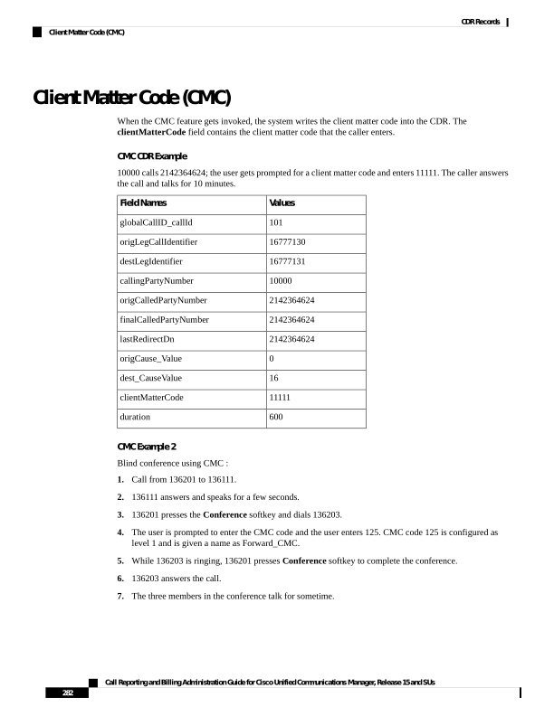
Page 295
136111 hangs sup, leaving 136201 and 136203 in the conference. Since there are only two participants
in the conference, the conference feature will join these two directly together and they talk for a few
seconds.
Final CDR
Conference
CDR 3
Conference
CDR 2
Conference
CDR 1
Setup Call
CDR
Orig Call
CDR
FieldNames
60027
60025
60025
60025
60026
60025
globalCallID_callId
23704527
23704526
23704522
23704523
23704524
23704522
origLegCallIdentifier
23704528
23704532
23704530
23704531
23704526
23704523
destLegIdentifier
136201
136203
136201
136111
136201
136201
callingPartyNumber
136203
b00105401002
b00105401002
b00105401002
136203
136111
origCalledPartyNumber
136203
b00105401002
b00105401002
b00105401002
136203
136111
finalCalledPartyNumber
136203
136201
136201
136201
136203
136111
lastRedirectDn
0
393216
393216
16
0
393216
origCause_Value
16
393216
393216
393216
0
393216
dest_CauseValue
Forward_CMC
authCodeDescription
0
0
0
0
1
0
authorizationLevel
48
25
32
32
0
20
Duration
125
authorizationCode
The setup call CDR for this example is generated even though it is of zero duration since CMC is used for
this call.
Note
Conference Calls
Multiple records get logged for calls that are part of a conference. The number of CDR records that get
generated depends on the number of parties in the conference. One CDR exists for each party in the conference;
one CDR for the original placed call, one CDR for each setup call that gets used to join other parties to the
conference, and one CDR for the last two parties that get connected in the conference. For a three-party, ad
hoc conference, six CDRs exist: one CDR for the original call, three CDRs for the parties that get connected
to the conference, one CDR for each setup call, and one CDR for the final two parties in the conference. You
can associate the setup calls with the correct call leg in the conference by examining the calling leg ID and
called leg ID.
The conference bridge device represents special significance to the Unified Communications Manager, and
calls to the conference bridge appear as calls to the conference bridge device. A special number in the form
“b0019901001” shows the conference bridge port. Records show all calls into the conference bridge, regardless
Call Reporting and Billing Administration Guide for Cisco Unified Communications Manager, Release 15 and SUs
283
CDR Records
Conference Calls

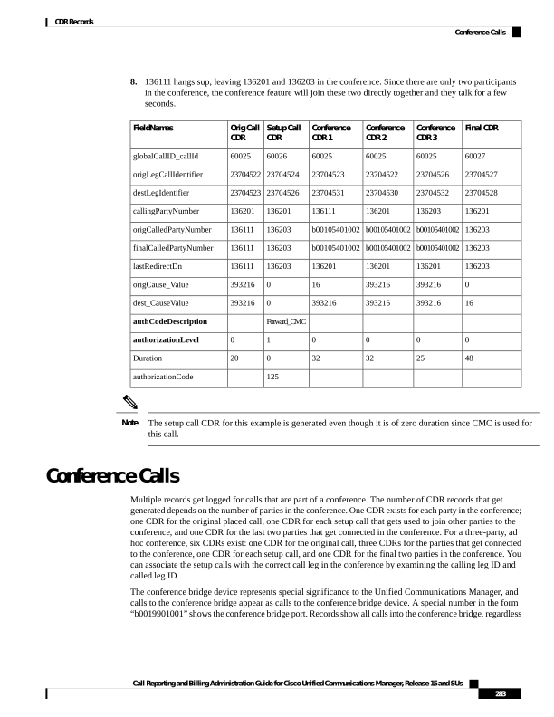
Page 296
of the actual direction; however, by examining the setup call CDRs, you can determine the original direction
of each call.
You can find the conference controller information in the comment field of the CDR. The format of this
information follows:
Comment field = “ConfControllerDn=1000;ConfControllerDeviceName=SEP0003”
• The conference controller DN + conference controller device name uniquely identify the conference
controller. The system needs the device name in the case of shared lines.
• If the call is involved in multiple conference calls, the comment field contains multiple conference
controller information. This situation can occur when the conference goes down to two parties, and one
of these parties starts another conference. If this is the case, the last conference controller information
in the comment field identifies the conference controller.
The call legs that are connected to the conference include the following information fields:
• The finalCalledPartyNumber field contains the conference bridge number “b0019901001.”
• The origCalledPtyRedirectOnBehalfOf field gets set to Conference = 4.
• The lastRedirectRedirectOnBehalfOf field gets set to Conference = 4.
• The joinOnBehalfOf field gets set to (Conference = 4).
• The comment field identifies the conference controller.
• The destConversationID field remains the same for all members in the conference. You can use
this field to identify members of a conference call.
The original placed call and all setup calls that were used to join parties to the conference have the following
characteristics:
• The origCallTerminationOnBehalfOf field gets set to Conference = 4.
• The destCallTerminationOnBehalfOf field gets set to Conference = 4.
Conference Call CDR Example
• Call goes from 2001 to 2309.
• 2309 answers and talks for 60 seconds.
• 2001 presses the conference softkey and dials 3071111.
• 307111 answers and talks for 20 seconds; then, 2001 presses the conference softkey to complete the
conference.
• The three members of the conference talk for 360 seconds.
3071111 hangs up and leaves 2001 and 2309 in the conference. Because only two participants are left in the
conference, the conference features joins these two directly together, and they talk for another 55 seconds.
Call Reporting and Billing Administration Guide for Cisco Unified Communications Manager, Release 15 and SUs
284
CDR Records
Conference Calls
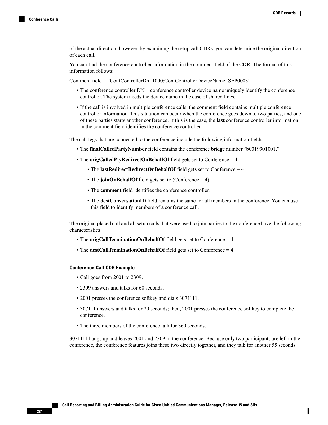
Page 297
Each conference call leg gets shown as placing a call into the conference bridge. The system shows the call
as a call into the bridge, regardless of the actual direction of the call.
Note
Final CDR
Conference CDR 3
Conference CDR 2
Conference CDR 1
Setup Call CDR
Orig Call CDR
Field Names
1
1
1
1
2
1
globalCallID_callId
101
106
102
101
105
101
origLegCallIdentifier
102
117
116
115
106
102
destLegIdentifier
2001
3071111
2309
2001
2001
2001
callingPartyNumber
2309
b0029901001
b0029901001
b0029901001
3071111
2309
originalCalledPartyNumber
2309
b0029901001
b0029901001
b0029901001
3071111
2301
finalCalledPartyNumber
b0029901001
b0029901001
b0029901001
b0029901001
3071111
2001
lastRedirectDn
16
393216
393216
16
0
393216
origCause_Value
0
393216
393216
393216
0
393216
dest_CauseValue
0
0
0
0
0
0
origCalledPartyRedirectReason
98
0
0
0
0
0
lastRedirectRedirectReason
12
4
12
12
4
4
origTerminationOnBehalfOf
4
4
0
0
4
4
destTerminationOnBehalfOf
0
4
4
4
0
0
origCalledRedirectOnBehalfOf
4
4
4
4
0
0
lastRedirectRedirectOnBehalfOf
4
4
4
4
0
0
joinOnBehalfOf
0
1
1
1
0
0
Conversation ID
55
360
360
360
20
60
duration
Comment
Orig Call CDR
ConfControllerDn=2001;ConfControlerDeviceName=SEP0003E333FEBD
Setup Call CDR
ConfControllerDn=2001;ConfControlerDeviceName=SEP0003E333FEBD
Conference CDR 1
ConfControllerDn=2001;ConfControlerDeviceName=SEP0003E333FEBD
Conference CDR 2
ConfControllerDn=2001;ConfControlerDeviceName=SEP0003E333FEBD
Conference CDR 3
Final CDR
Call Reporting and Billing Administration Guide for Cisco Unified Communications Manager, Release 15 and SUs
285
CDR Records
Conference Calls

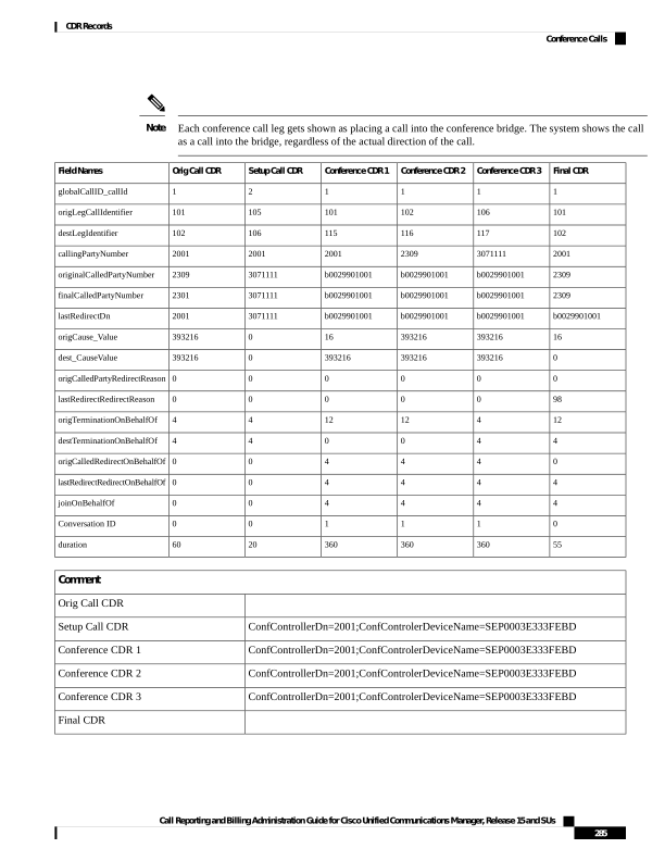
Page 298
Operational Factors
Three major operational factors exist for conference call CDRs:
1.
When a conference decreases to two parties, the two parties connect directly and release the conference
resource. This change generates an additional CDR for the call between the last two parties in the conference
call.
For example, if four people connect in a conference call (Amy, Dustin, Spencer, Ethan), when Ethan
hangs up, three people remain in the conference call that is connected to the conference bridge (Amy,
Dustin, Spencer). When Spencer hangs up, only two people remain in the conference call (Amy and
Dustin). The system joins Amy and Dustin directly, and, the conference resource gets released. Directly
joining Amy and Dustin creates an additional CDR between the last two parties in the conference.
2.
The system adds the conference controller information to the comment field in the CDR. This information
identifies the conference controller. No need now exists to examine the consultation call to determine
who is the conference controller. The following example shows this information:
Comment field = “ConfControllerDn=1000;ConfControllerDeviceName=SEP0003E333FEBD”
• The conference controller DN + conference controller device name uniquely identify the conference
controller. A need for the device name exists in the case of shared lines.
• If the call is involved in multiple conference calls, the comment field contains multiple conference
controller information. This situation may occur when the conference goes down to two parties, and
one of these parties starts another conference. If this is the case, the last conference controller
information in the comment field identifies the conference controller.
3.
The party that added the participant, known as the requestor party, appears in the CDR comment field.
The tags for the requestor information include ConfRequestorDn and ConfRequestorDeviceName. The
party that requested to remove a participant, known as the drop requestor, appears in the CDR comment
field. The tags for the drop requestor information include DropConfRequestorDn and
DropConRequestorDeviceName.
Calls that are part of a conference have multiple records that are logged for them. The number of CDRs that
get generated depends on the number of parties in the conference. One CDR exists for each party in the
conference, one CDR for the original placed call, and one CDR for each setup call that is used to join other
parties to the conference. Therefore, for a three-party ad hoc conference, six CDRs exist:
• One CDR for the original call.
• Three CDRs for the parties that are connected to the conference.
• One CDR for each setup call.
• One CDR for the final two parties in the conference.
You can associate the setup calls with the correct call leg in the conference by examining the callinglegID
and the calledlegID.
The conference bridge device holds special significance to the Unified Communications Manager. Calls to
the conference bridge appear as calls to the conference bridge device. A special number in the form
“b0019901001” shows the conference bridge port. All calls get shown “into” the conference bridge, regardless
of the actual direction. You can determine the original direction of each call by examining the setup call CDRs.
The call legs that are connected to the conference have the following values for these fields:
Call Reporting and Billing Administration Guide for Cisco Unified Communications Manager, Release 15 and SUs
286
CDR Records
Operational Factors
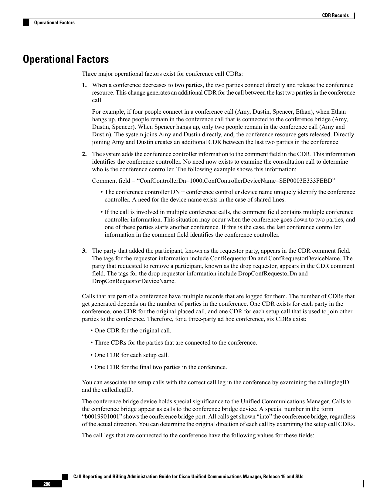
Page 299
• finalCalledPartyNumber—Represents a conference bridge “b0019901001”.
• origCalledPartyRedirectOnBehalfOf—Set to Conference (4).
• lastRedirectRedirectOnBehalfOf—Set to Conference (4).
• joinOnBehalfOf—Set to Conference (4).
• comment—Identifies the conference controller.
The original placed call and all setup calls that get used to join parties to the conference have the following
values for the fields:
• origCallTerminationOnBehalfOf—Set to Conference (4).
• destCallTerminationOnBehalfOf—Set to Conference (4).
Conference Now Calls
This feature allows both external and internal callers to join a conference by dialing a Conference Now IVR
Directory Number. An Interactive Voice Response (IVR) application guides the caller to join the conference
by playing an announcement and collecting caller entered DTMF digits.
A conference call using the Conference Now feature logs multiple CDR records for a call. The number of
CDR records that get generated depends on the number of parties in the conference. One CDR exists for each
party in the conference; one CDR for the original placed call, and one CDR for each setup call that get used
to join the conference bridge. For a two-party, Conference Now, four CDRs exists: two CDR for the original
call, and two CDR for parties that get connected to the conference bridge.
The conference bridge device represents special significance to the Unified Communications Manager, and
calls to the conference bridge appear as calls to the conference bridge device. A special number in the form
“b00105401006” shows the conference bridge port. Records show all calls into the conference bridge, regardless
of the actual direction; however, by examining the setup call CDRs, you can determine the original direction
of each call.
You can find the Conference Now host information in the comment field of the CDR. The comments field
will only be populated for redirection of the call to the CFB. The format of this information follows:
Comment field = “ConferenceNowHostId =john; ConferenceNowMeetingNumber=136136”.
The ConferenceNowHostId+ConferenceNowMeetingNumber uniquely identifies the Conference Now
information.
The call legs that are connected to the conference include the following information fields:
• The finalCalledPartyNumber field contains the conference bridge number “b00105401006”.The
finalCalledPartyNumber field in case of initial call when it connects to IVR contains the IVR directory
number “c00124401001”.
• The origCalledPtyRedirectOnBehalfOf field is set to (Meet-me Conference Intercepts= 7).
• The lastRedirectRedirectOnBehalfOf field is set to (Meet-me Conference Intercepts= 7).
• The joinOnBehalfOf field is set to (Meet-me Conference Intercepts=7).
• The comment field identifies ConfrenceNowHostId and ConferenceNowMeetingNumber.
Call Reporting and Billing Administration Guide for Cisco Unified Communications Manager, Release 15 and SUs
287
CDR Records
Conference Now Calls
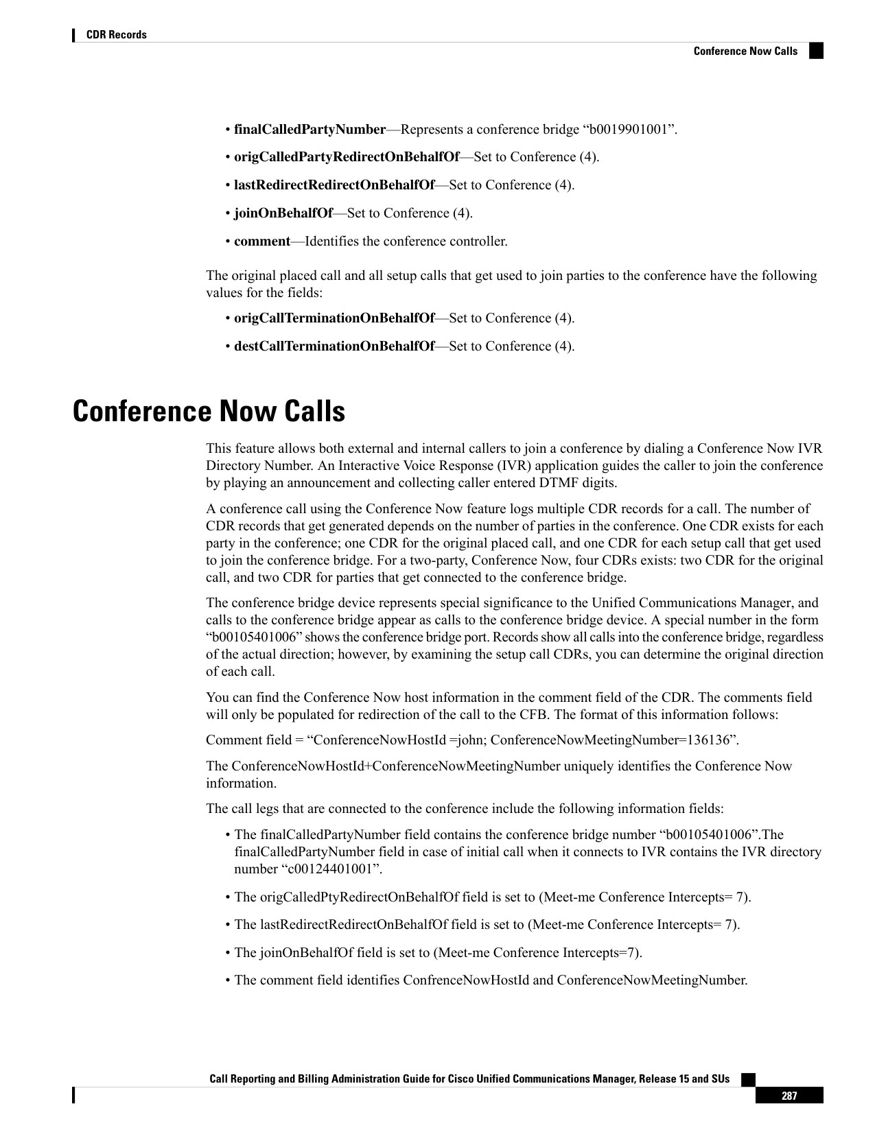
Page 300
• The destConversationId field is the same for all members in the conference. This field can be used to
identify members of a conference call.
The original placed call and all setup calls that were used to join parties to the conference have the following
characteristics:
• The origCallTerminationOnBehalfOf field is set to (Meet-me Conference Intercepts= 7).
• The destCallTerminationOnBehalfOf field is set to (Meet-me Conference Intercepts= 7).
ConferenceNow CDR Example
The following table contains an example CDR for the following scenario.
• User A (139139) calls into a Conference Now conference bridge with the phone number 1010.
• User A (139139) connects to IVR and IVR requests for a Meeting Number.
• User A (139139) dials the Meeting Number “ 136136” followed by #.
• User A (139139) joins as an attendee; therefore presses # and then enters attendee access code followed
by #.
• User A (139139) is placed on Music On Hold (MoH).
• User B (136136) dials the Conference Now phone number 1010.
• User B (136136) connects to IVR and the IVR requests for a Meeting Number.
• User B (136136) dials in the Meeting Number followed by #.
• User B (136136) enters the host pin followed by # as the user is joining the conference call as a host.
• Both the attendee and the host get redirected to Conference Bridge and are placed into conference.
Conference CDR 2
Orig Call CDR2
Conference CDR 1
Orig Call CDR1
FieldNames
47003
47003
47002
47002
globalCallID_callId
20795098
20795098
20795093
20795093
origLegCallIdentifier
20795103
20795101
20795104
20795096
destLegIdentifier
136136
136136
139139
139139
callingPartyNumber
1010
1010
1010
1010
originalCalledPartyNumber
b00105401006
c00124401001
b00105401006
c00124401001
finalCalledPartyNumber
c00124401001
1010
c00124401001
1010
lastRedirectDn
16
0
16
0
origCause_Value
0
0
0
0
dest_CauseValue
0
0
0
0
origCalledPartyRedirectReason
0
0
0
0
lastRedirectRedirectReason
12
7
12
7
origTerminationOnBehalfOf
Call Reporting and Billing Administration Guide for Cisco Unified Communications Manager, Release 15 and SUs
288
CDR Records
Conference Now Calls
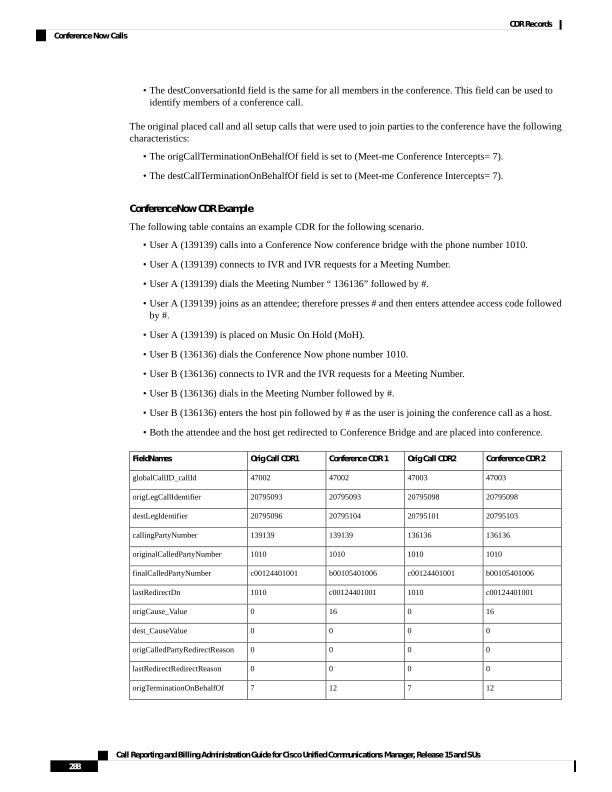
Page 301
Conference CDR 2
Orig Call CDR2
Conference CDR 1
Orig Call CDR1
FieldNames
7
7
7
7
destTerminationOnBehalfOf
0
0
0
0
origCalledRedirectOnBehalfOf
7
0
7
0
lastRedirectRedirectOnBehalfOf
7
0
7
0
joinOnBehalfOf
16809217
0
16809217
0
Conversation ID
9
10
20
14
duration
Comment
Orig Call CDR 1
ConferenceNowHostID=Rishi;ConferenceNowMeetingNumber=136136
Conference CDR 1
Orig Call CDR 2
ConferenceNowHostID=Rishi;ConferenceNowMeetingNumber=136136
Conference CDR 2
Conference Drop Any Party
The Conference Drop Any Party feature terminates calls that look the same as other calls except for a new
cause code. The cause code identifies the calls that this feature terminates.
Conference Drop Any Party CDR Example
The following table contains an example CDR for a call that connects to a conference and gets dropped by
this feature.
Last Redirec
Party
Final Called
Partition
Final Called
Party
Dest
Cause
Called
Leg
Original
Called
Partition
Orig
Cause
Original Called
Party
Calling
Partition
Calling
Party
2001
MKTG
2309
16
102
MKTG
0
2309
ACNTS
2001
b002990100
b0029901001
0
115
MKTG
16
2309
ACNTS
2001
b002990100
b0029901001
128
116
0
b0029901001
ACNTS
2309
b002990100
b0029901001
0
117
16
b0029901001
PSTN
3071111
30711111
PSTN
3071111
0
106
PSTN
16
2309
ACNTS
2001
Duration
Join
OnBehalfOf
LastRedirect
Redirect
OnBehalfOf
OriginalCalled
Pty Redirect
OnBehalfOf
DestCall
Termination
OnBehalfOf
OrigCall
Termination
OnBehalfOf
Orig
Conversation
ID
60
0
0
0
4
4
0
Call Reporting and Billing Administration Guide for Cisco Unified Communications Manager, Release 15 and SUs
289
CDR Records
Conference Drop Any Party
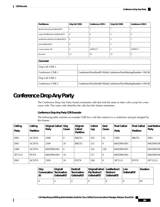
Page 302
Duration
Join
OnBehalfOf
LastRedirect
Redirect
OnBehalfOf
OriginalCalled
Pty Redirect
OnBehalfOf
DestCall
Termination
OnBehalfOf
OrigCall
Termination
OnBehalfOf
Orig
Conversation
ID
360
4
4
4
0
12
1
200
4
4
4
0
13
1
360
4
4
4
4
4
1
20
0
0
0
4
4
0
Original Calling Party on Transfer
DTMF Method
These fields identify the Dual Tone Multi-Frequency (DTMF) method that gets used for the call.
DTMF CDR Examples
1.
No Preference Example - The DTMF method that gets used during this call represents No Preference/Best
Effort. This call connects for 1minute.
CDR
Field Names
200
globalCallID_callId
16777500
origLegCallIdentifier
16777501
destLegIdentifier
20000
callingPartyNumber
20001
origCalledPartyNumber
20001
finalCalledPartyNumber
20001
lastRedirectDn
0
origCause_Value
16
dest_CauseValue
0
origDTMFMethod
0
destDTMFMethod
60
duration
1.
Preferred OOB Example - The DTMF method that is used during this call represents OOB Preferred.
This call remains connected for 1minute.
Call Reporting and Billing Administration Guide for Cisco Unified Communications Manager, Release 15 and SUs
290
CDR Records
Original Calling Party on Transfer
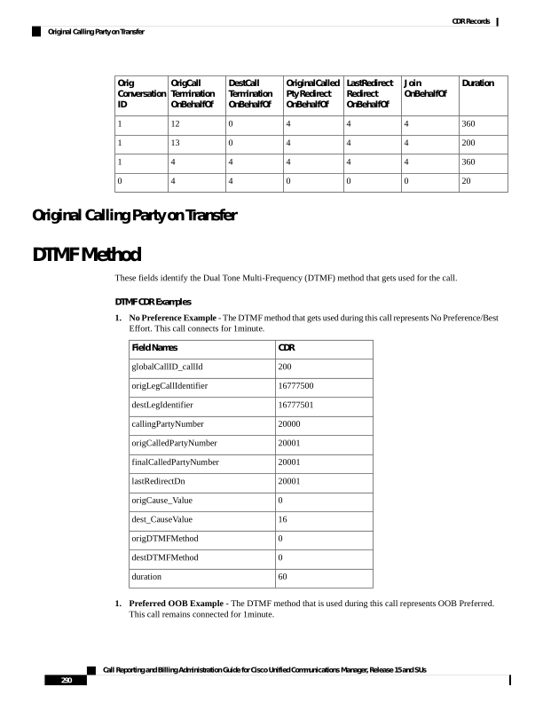
Page 303
CDR
Field Names
201
globalCallID_callId
16777502
origLegCallIdentifier
16777503
destLegIdentifier
20000
callingPartyNumber
20001
origCalledPartyNumber
20001
finalCalledPartyNumber
20001
lastRedirectDn
0
origCause_Value
16
dest_CauseValue
1
origDTMFMethod
1
destDTMFMethod
60
duration
End-to-End Call Trace
The End-to-End Call Trace feature facilitates tracing calls that traverse multiple Cisco voice products, such
as Unified CM, Cisco IOS Gateways, and other products.
End-to-End Call Trace Example
1.
H323 - Calling party 1003 calls 1004 via H.323 trunk.
Values
FieldNames
1
cdrRecordType
1
globalCallID_callManagerId
32009
globalCallID_callId
19654113
origLegCallIdentifier
1221263718
dateTimeOrigination
1
origNodeId
0
origSpan
1897990154
origIpAddr
Call Reporting and Billing Administration Guide for Cisco Unified Communications Manager, Release 15 and SUs
291
CDR Records
End-to-End Call Trace
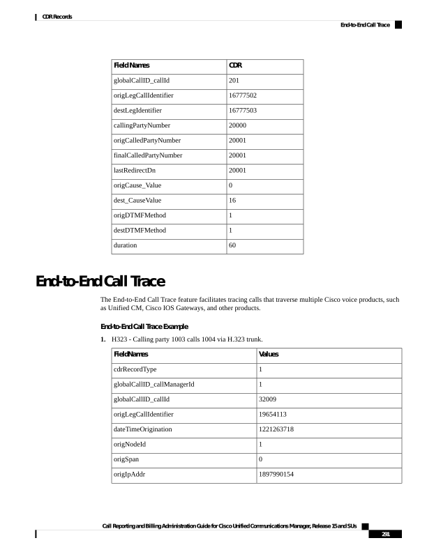
Page 304
Values
FieldNames
1004
callingPartyNumber
16
origCause_value
4
origPrecedenceLevel
1897990154
origMediaTransportAddress_IP
19824
origMediaTransportAddress_Port
4
origMediaCap_payloadCapability
20
origMediaCap_maxFramesPerPacket
19654114
destLegIdentifier
1
destNodeId
19654114
destSpan
424630538
destIpAddr
1003
originalCalledPartyNumber
1003
finalCalledPartyNumber
0
destCause_value
4
destPrecedenceLevel
-1759442934
destMediaTransportAddress_IP
27508
destMediaTransportAddress_Port
4
destMediaCap_payloadCapability
20
destMediaCap_maxFramesPerPacket
1221263720
dateTimeConnect
1221263721
dateTimeDisconnect
1003
lastRedirectDn
c8868f84-0f4e-452c-a814-bf97a7fe69fc
Pkid
1
Duration
SEP003094C2B08C
origDeviceName
self-loop
destDeviceName
12
origCallTerminationOnBehalfOf
0
destCallTerminationOnBehalfOf
Call Reporting and Billing Administration Guide for Cisco Unified Communications Manager, Release 15 and SUs
292
CDR Records
End-to-End Call Trace
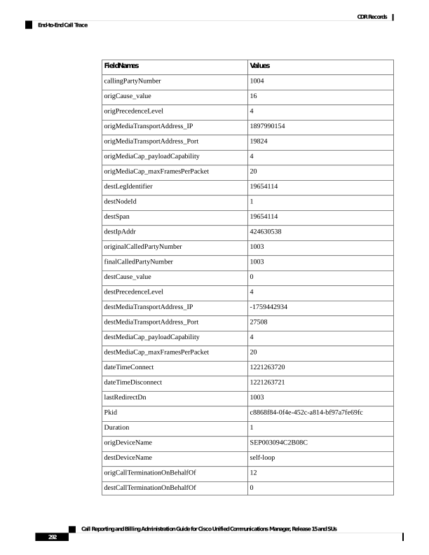
Page 305
Values
FieldNames
3
origDTMFMethod
4
destDTMFMethod
64
origMediaCap_Bandwidth
64
destMediaCap_Bandwidth
10.8.33.113
origIpv4v6Addr
10.8.33.151
destIpv4v6Addr
0
IncomingProtocolID
IncomingProtocolCallRef
2
OutgoingProtocolID
0053C43F6701B18C030004010A082171
OutgoingProtocolCallRef
2.
Q931 - 1004 calls 1003 via Q931.
Values
FieldNames
1
cdrRecordType
1
globalCallID_callManagerId
32008
globalCallID_callId
19654111
origLegCallIdentifier
1221263350
dateTimeOrigination
1
origNodeId
2
origSpan
122640650
origIpAddr
1004
callingPartyNumber
0
origCause_value
4
origPrecedenceLevel
122640650
origMediaTransportAddress_IP
17218
origMediaTransportAddress_Port
4
origMediaCap_payloadCapability
20
origMediaCap_maxFramesPerPacket
Call Reporting and Billing Administration Guide for Cisco Unified Communications Manager, Release 15 and SUs
293
CDR Records
End-to-End Call Trace
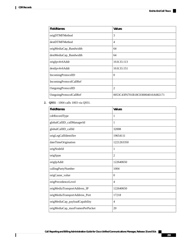
Page 306
Values
FieldNames
19654112
destLegIdentifier
1
destNodeId
0
destSpan
-1759442934
destIpAddr
1003
originalCalledPartyNumber
1003
finalCalledPartyNumber
16
destCause_value
4
destPrecedenceLevel
-1759442934
destMediaTransportAddress_IP
23350
destMediaTransportAddress_Port
4
destMediaCap_payloadCapability
20
destMediaCap_maxFramesPerPacket
1221263351
dateTimeConnect
1221263352
dateTimeDisconnect
1003
lastRedirectDn
b576bd8d-9703-4f66-ae45-64ae5c04738e
Pkid
1
Duration
BRI/S1/SU0/P1@nw052b-3640.cisco.com
origDeviceName
SEP003094C2D263
destDeviceName
0
origCallTerminationOnBehalfOf
12
destCallTerminationOnBehalfOf
1
origDTMFMethod
3
destDTMFMethod
64
origMediaCap_Bandwidth
64
destMediaCap_Bandwidth
10.89.79.7
origIpv4v6Addr
10.8.33.151
destIpv4v6Addr
4
IncomingProtocolID
Call Reporting and Billing Administration Guide for Cisco Unified Communications Manager, Release 15 and SUs
294
CDR Records
End-to-End Call Trace
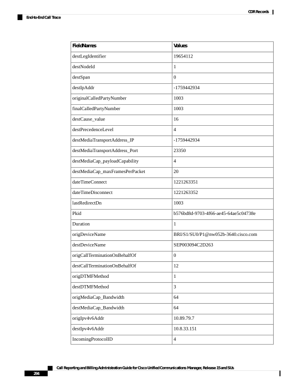
Page 307
Values
FieldNames
01-1004-1003
IncomingProtocolCallRef
0
OutgoingProtocolID
OutgoingProtocolCallRef
Forced Authorization Code (FAC)
When the FAC feature gets invoked, the system writes the authorization description and level into the CDR.
For security reasons, the actual authorization code does not get written to the CDR.
• The authCodeDescription field contains the description of the authorization code.
• The authorizationLevel field contains the level of authorization that is associated with the authorization
code.
FAC CDR Example 1
45000 calls 9728134987; the system prompts the user for an authorization code and enters 12345. FAC code
12345 gets configured as level 1 and name Legal1. The caller answers the call and talks for 2minutes.
Values
Field Names
100
globalCallID_callId
16777123
origLegCallIdentifier
16777124
destLegIdentifier
45000
callingPartyNumber
9728134987
origCalledPartyNumber
9728134987
finalCalledPartyNumber
9728134987
lastRedirectDn
0
origCause_Value
16
dest_CauseValue
Legal1
authCodeDescription
1
authorizationLevel
120
duration
12345
authorizationCode
CDR will now be written for a setup call leg for all the unanswered calls before the call is redirected to another
caller if FAC is used to setup the call.
Call Reporting and Billing Administration Guide for Cisco Unified Communications Manager, Release 15 and SUs
295
CDR Records
Forced Authorization Code (FAC)
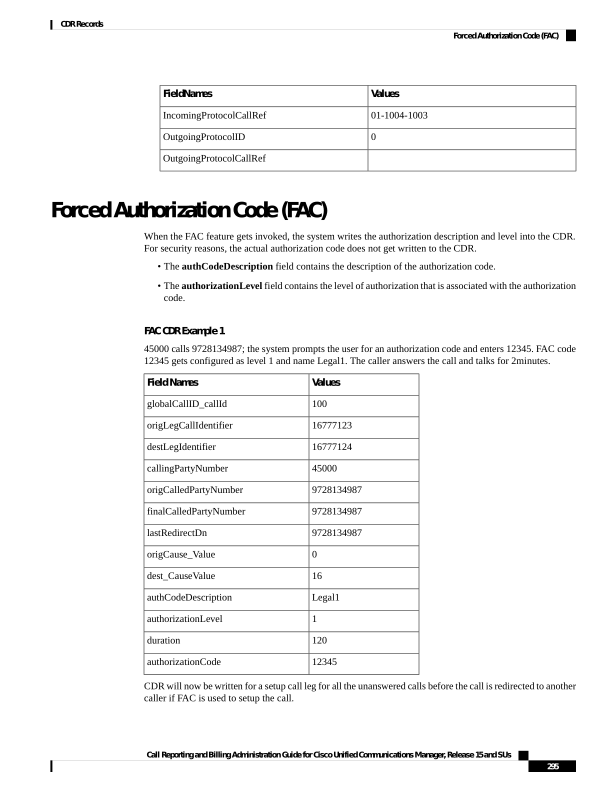
Page 308
The unanswered call will not have any connect time since media is not connected for this call. The CDR will
be logged regardless of the service parameter CdrLogCallsWithZeroDurationFlag if FAC is present in the
call.
Note
FAC Example 2
Blind conference using FAC:
1.
Call from 136201 to 136111.
2.
136111 answers and speaks for a few seconds.
3.
136201 presses the Conference softkey and dials 136203.
4.
The user is prompted to enter the FAC code and the user enters 124. FAC code 124 is configured as level
1 and given a name as Forward_FAC.
5.
While 136203 is ringing, 136201 presses the Conference softkey to complete the conference.
6.
136203 answers the call.
7.
The three members in the conference talk for sometime.
8.
136111 hangs up, leaving 136201 and 136203 in the conference. Since there are only two participants in
the conference, the conference feature will join these two directly together and they talk for a few seconds.
Final CDR
Conference
CDR 3
Conference
CDR 2
Conference
CDR 1
Setup Call
CDR
Orig Call
CDR
FieldNames
60017
60015
60015
60015
60016
60015
globalCallID_callId
23704377
23704376
23704372
23704373
23704374
23704372
origLegCallIdentifier
23704378
23704382
23704380
23704381
23704376
23704373
destLegIdentifier
136201
136203
136201
136111
136201
136201
callingPartyNumber
136203
b00105401002
b00105401002
b00105401002
136203
136111
origCalledPartyNumber
136203
b00105401002
b00105401002
b00105401002
136203
136111
finalCalledPartyNumber
136203
136201
136201
136201
136203
136111
lastRedirectDn
0
393216
393216
16
0
393216
origCause_Value
16
393216
393216
393216
0
393216
dest_CauseValue
Forward_FAC
authCodeDescription
0
0
0
0
1
0
authorizationLevel
38
32
37
37
0
18
Duration
124
authorizationCode
Call Reporting and Billing Administration Guide for Cisco Unified Communications Manager, Release 15 and SUs
296
CDR Records
Forced Authorization Code (FAC)

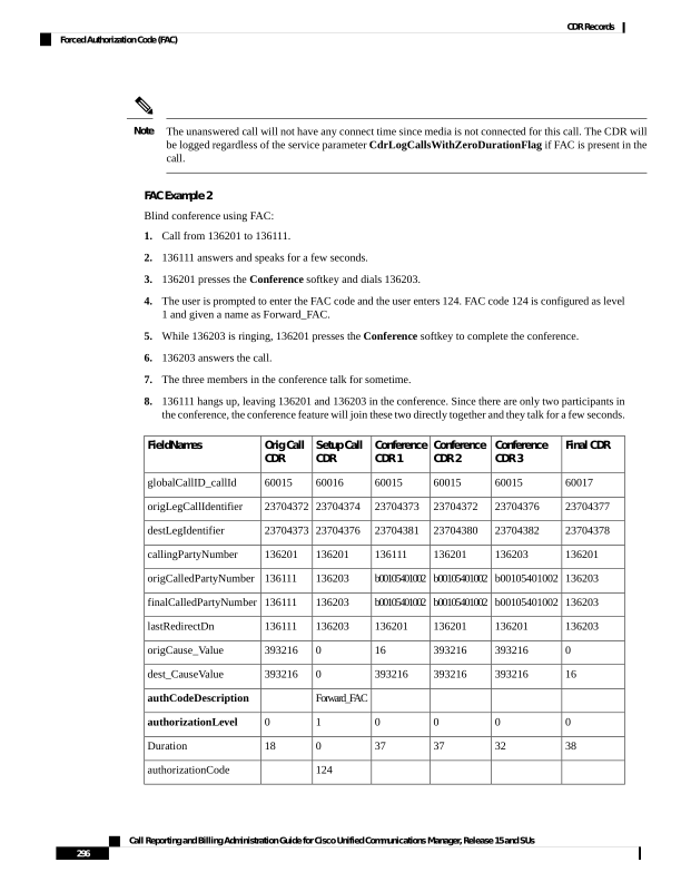
Page 309
The setup call CDR for this example is generated even though it is of zero duration since FAC is used for this
call.
Note
Forwarded or Redirected Calls
Forwarded calls generate a single CDR and show the Calling Party, Original Called Number, Last Redirecting
Number, Final Called Number, and the associated partitions. If the call gets forwarded more than twice, the
intermediate forwarding parties do not populate in the CDR.
Call forwarding can occur on several conditions (always, busy, and no answer). The condition under which
the call gets forwarded does not populate in the CDR.
The CDRs for forwarded calls match those for normal calls, except for the originalCalledPartyNumber field
and the originalCalledPartyNumberPartition field. These fields contain the directory number and partition for
the destination that was originally dialed by the originator of the call. If the call gets forwarded, the
finalCalledPartyNumber and finalCalledPartyNumberPartition fields differ and contain the directory number
and partition of the final destination of the call.
Also, when a call gets forwarded, the lastRedirectDn and lastRedirectDnPartition fields contain the directory
number and partition of the last phone that forwarded or redirected the call.
Call Forwarding uses the redirect call primitive to forward the call. Features that use the redirect call primitive
have similar CDRs. Some of the important CDR fields for forwarded calls follow:
• The originalCalledPartyNumber contains the number of the original called party.
• The finalCalledPartyNumber represents the number that answered the call.
• The lastRedirectDn field specifies the number that performed the last redirect.
• The origCalledPartyRedirectReason represents the reason that the call was redirected the first time.
For call forwarding, this field can contain Call Forward Busy=1, Call Forward No Answer=2, Call
Forward All=15.
• The lastRedirectRedirectReason specifies the reason that the call was redirected the last time. For call
forwarding, this field can contain Call Forward Busy=1, Call Forward No Answer=2, Call Forward
All=15.
• The origCalledPartyRedirectOnBehalfOf field identifies which feature redirects the call for the first
redirect. For call forwarding, this field specifies 5 (Call Forward).
• The lastRedirectRedirectOnBehalfOf field identifies which feature redirects the call for the last redirect.
For call forwarding, this field specifies 5 (Call Forward).
Forwarded Calls CDR Examples
1.
CFA - Call comes in from the PSTN to extension 2001; the call gets forwarded (CFA) to 2309, where
the call is answered, and talk occurs for 2minutes.
CDR
Field Names
12345
globalCallID_callId
Call Reporting and Billing Administration Guide for Cisco Unified Communications Manager, Release 15 and SUs
297
CDR Records
Forwarded or Redirected Calls

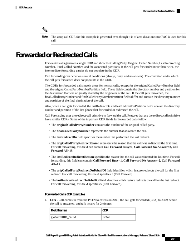
Page 310
CDR
Field Names
100
origLegCallIdentifier
102
destLegIdentifier
9728134987
callingPartyNumber
2001
originalCalledPartyNumber
2309
finalCalledPartyNumber
2001
lastRedirectDn
0
origCause_Value
16
dest_CauseValue
15
origCalledPartyRedirectReason
15
lastRedirectRedirectReason
5
origCalledPartyRedirectOnBehalfOf
5
lastRedirectRedirectOnBehalfOf
120
duration
2.
Multiple Hop CFA & CFNA - Call comes in from the PSTN to extension 1000; the call gets forwarded
(CFA) to 2000; then, the call gets forwarded (CFNA) to the voice-messaging system (6000) where the
caller leaves a message.
CDR
Field Names
12346
globalCallID_callId
102
origLegCallIdentifier
105
destLegIdentifier
9728134987
callingPartyNumber
1000
originalCalledPartyNumber
6000
finalCalledPartyNumber
2000
lastRedirectDn
0
origCause_Value
16
dest_CauseValue
15
origCalledPartyRedirectReason
2
lastRedirectRedirectReason
Call Reporting and Billing Administration Guide for Cisco Unified Communications Manager, Release 15 and SUs
298
CDR Records
Forwarded or Redirected Calls
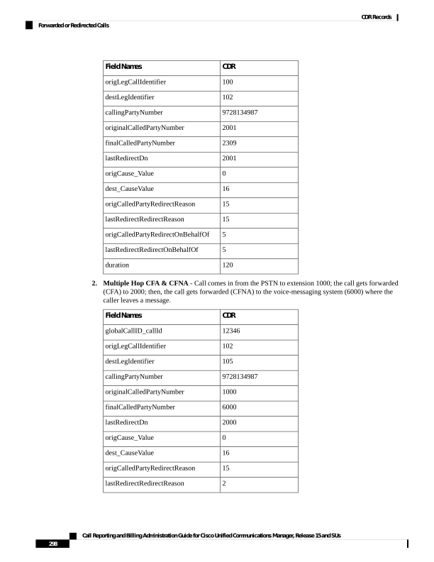
Page 311
CDR
Field Names
5
origCalledPartyRedirectOnBehalfOf
5
lastRedirectRedirectOnBehalfOf
15
duration
3.
Multiple Hop CFNA & CFB - Call comes in from the PSTN to extension 4444; the call gets forwarded
(CFNA) to 5555; then, it gets forwarded (CFB) to 6666 where the call is answered, and they talk for 30
seconds.
CDR
Field Names
12347
globalCallID_callId
106
origLegCallIdentifier
108
destLegIdentifier
9728134987
callingPartyNumber
4444
originalCalledPartyNumber
6666
finalCalledPartyNumber
5555
lastRedirectDn
16
origCause_Value
0
dest_CauseValue
2
origCalledPartyRedirectReason
1
lastRedirectRedirectReason
5
origCalledPartyRedirectOnBehalfOf
5
lastRedirectRedirectOnBehalfOf
30
duration
Hunt List Support
Hunt List Examples
1.
Answered Calls - In this example, calls go to a hunt list and a member of the hunt list answers the call.
• Cisco Unified IP Phones 3001, 3002, 3003 and 3004 are part of the hunt list. The display names for
the phones are 3001-Name, 3002-Name, 3003-Name and 3004-Name, respectively.
• Hunt Pilot 2000 is associated with a hunt list. Hunt pilot 2000 is configured with display name as
2000-Name.
Call Reporting and Billing Administration Guide for Cisco Unified Communications Manager, Release 15 and SUs
299
CDR Records
Hunt List Support
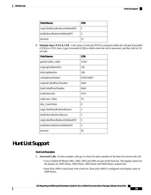
Page 312
• Phone 1000 calls hunt pilot 2000; call is offered at 3001 and answered.
When the Show Line Group Member DN in finalCalledPartyNumber CDR Field service parameter is
set to True, the following values appear in the CDR.
CDR
Field Names
1000
callingPartyNumber
callingPartyNumberPartition
2000
originalCalledPartyNumber
originalCalledPartyNumberPartition
3001
finalCalledPartyNumber
finalCalledPartyNumberPartition
Phone 1000
origDeviceName
Phone 3001
destDeviceName
2000
huntPilotDN
huntPilotPartition
When the Show Line Group Member DN in finalCalledPartyNumber CDR Field service parameter is
set to False, the following values in the table display in the CDR.
CDR
Field Names
1000
callingPartyNumber
callingPartyNumberPartition
2000
originalCalledPartyNumber
originalCalledPartyNumberPartition
2000
finalCalledPartyNumber
finalCalledPartyNumberPartition
Phone 1000
origDeviceName
Phone 3001
destDeviceName
2000
huntPilotDN
huntPilotPartition
1.
Abandoned or Failed Calls - In this example, calls go to a hunt list and a member of the hunt list abandons
or fails the call.
• Cisco Unified IP Phones 3001, 3002, 3003 and 3004 are part of the hunt list.
Call Reporting and Billing Administration Guide for Cisco Unified Communications Manager, Release 15 and SUs
300
CDR Records
Hunt List Support
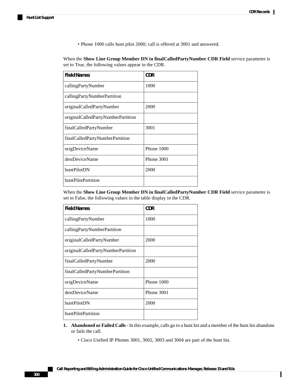
Page 313
• Hunt Pilot 2000 is associated with a hunt list.
• Phone 1000 calls hunt pilot 2000; call is offered at 3001 and abandoned. When the Show Line Group
Member DN in finalCalledPartyNumber CDR field service parameter is set to True, the following
values from the table display in the CDR:
CDR
Field Names
1000
callingPartyNumber
callingPartyNumberPartition
2000
originalCalledPartyNumber
originalCalledPartyNumberPartition
2000
finalCalledPartyNumber
finalCalledPartyNumberPartition
Phone 1000
origDeviceName
Phone 3001
destDeviceName
huntPilotDN
huntPilotPartition
7
calledPartyPatternUsage
If the call is not answered by any of the hunt group members, the finalCalledPartyNumber field shows the
hunt pilot DN. The number shows a line group member DN only when one of the line group member answers
the call.
Note
Because the call does not get answered, the huntPilotDN is not available in the CDR. The PatternUsage (7
= PATTERN_HUNT_PILOT) field gets set to 7 to indicate that the call was made to a hunt pilot. When the
service parameter is enabled, the finalCalledPartyNumber field denotes the member hunt DN and the
originalCalledPartyNumber field denotes the huntPilot DN.
When the Show Line Group Member DN in the finalCalledPartyNumber CDR field service parameter
is set to False, the following values in the table display in the CDR:
CDR
Field Names
1000
callingPartyNumber
callingPartyNumberPartition
2000
originalCalledPartyNumber
originalCalledPartyNumberPartition
Call Reporting and Billing Administration Guide for Cisco Unified Communications Manager, Release 15 and SUs
301
CDR Records
Hunt List Support

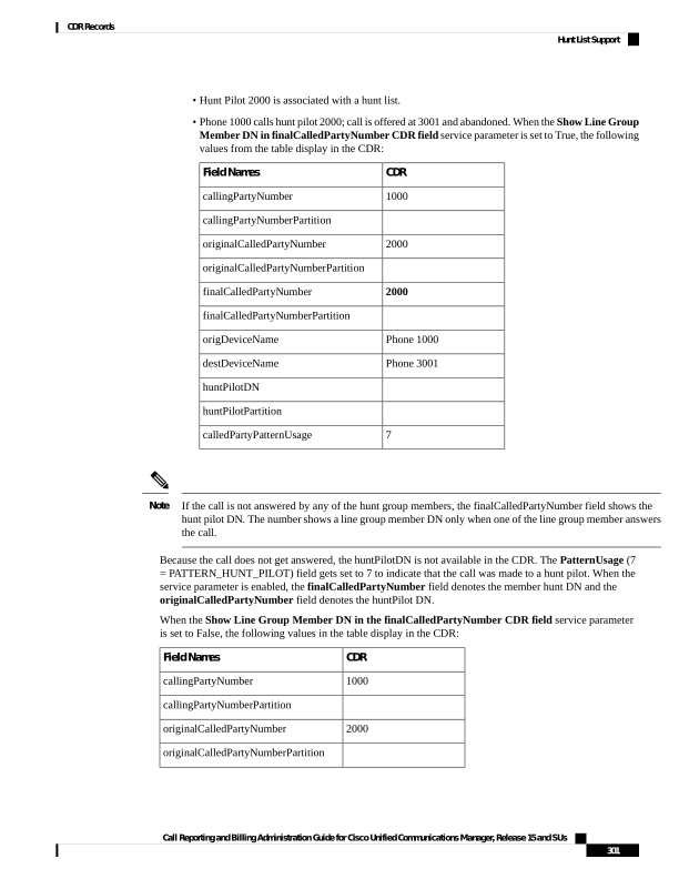
Page 314
CDR
Field Names
2000
finalCalledPartyNumber
finalCalledPartyNumberPartition
Phone 1000
origDeviceName
Phone 3001
destDeviceName
huntPilotDN
huntPilotPartition
7
calledPartyPatternUsage
Because the call is not answered, the huntPilotDN is not available in the CDR. The PatternUsage (7 =
PATTERN_HUNT_PILOT) field gets set to 7 to indicate that the call was made to a hunt pilot. When the
service parameter is not enabled, the finalCalledPartyNumber field denotes the member hunt DN.
H.239
Unified Communications Manager supports H.239. This feature defines the procedures for use of up to two
video channels in H.320-based systems and for labeling individual channels with a role of “presentation” or
“live.” This procedure indicates the requirements for processing the channel and the role of the channel content
in the call. Role labels apply to both H.320 and H.245 signaling-based systems.
Several new CDR fields support a second video channel for both the origination and destination devices. This
CDR provides an example of these new fields.
H.239 CDR Example
When A and B declare H.239 capability in Terminal Capability Set (TCS) and one, or both, of the endpoints
initiates the receiving channel to have an extended video channel in an H.239 mechanism for presentation or
video feed, the new CDR fields display in the CDR in addition to the existing fields of a video call.
Calling party 51234 calls the called party 57890. Let 103 represent H.264, 187962284 represents 172.19.52.11,
288625580 represents 172.19.52.17, and 352 represents 352K.
CDR
Field Names
121
globalCallID_callId
101
origLegCallIdentifier
102
destLegIdentifier
51234
callingPartyNumber
57890
originalCalledPartyNumber
57890
finalCalledPartyNumber
57890
lastRedirectDn
Call Reporting and Billing Administration Guide for Cisco Unified Communications Manager, Release 15 and SUs
302
CDR Records
H.239
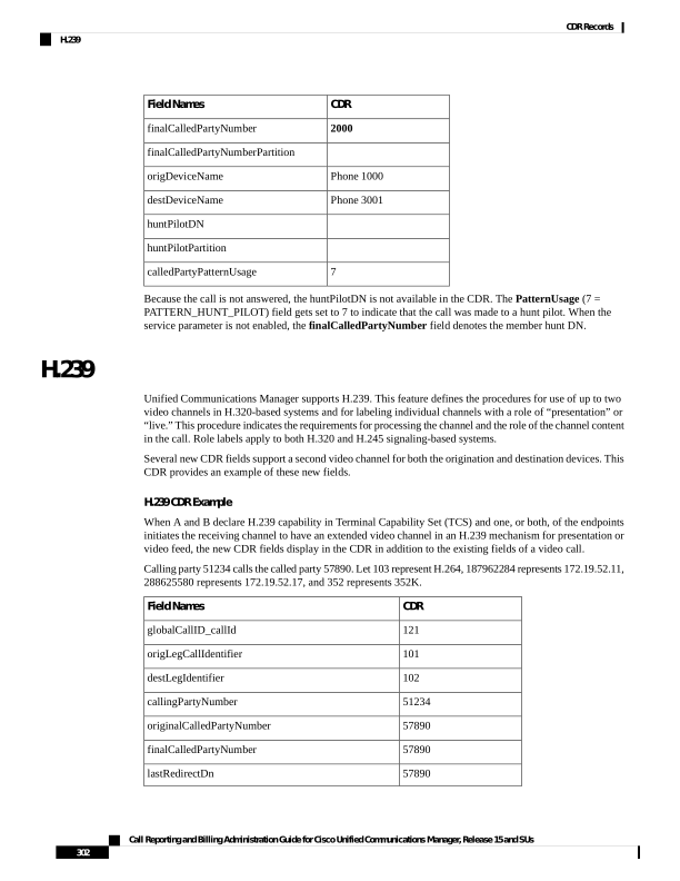
Page 315
CDR
Field Names
0
origCause_Value
16
destCause_Value
103
origVideoCap_Codec
352
origVideoCap_Bandwidth
0
origVideoCap_Resolution
187962284
origVideoTransportAddress_IP
2406
origVideoTransportAddress_Port
103
destVideoCap_Codec
352
destVideoCap_Bandwidth
0
destVideoCap_Resolution
288625580
destVideoTransportAddress_IP
2328
destVideoTransportAddress_Port
103
origVideoCap_Codec_Channel2
352
origVideoCap_Bandwidth_Channel2
0
origVideoCap_Resolution_Channel2
187962284
origVideoTransportAddress_IP_Channel2
2410
origVideoTransportAddress_Port_Channel2
0
origVideoChannel_Role_Channel2
103
destVideoCap_Codec_Channel2
352
destVideoCap_Bandwidth_Channel2
0
destVideoCap_Resolution_Channel2
288625580
destVideoTransportAddress_IP_Channel2
2330
destVideoTransportAddress_Port_Channel2
0
destVideoChannel_Role_Channel2
iLBC Calls
Internet Low Bit Rate Codec (iLBC) enables graceful speech quality degradation in a lossy network where
frames get lost. For iLBC calls, the codec specifies Media_Payload_ILBC = 86.
Call Reporting and Billing Administration Guide for Cisco Unified Communications Manager, Release 15 and SUs
303
CDR Records
iLBC Calls
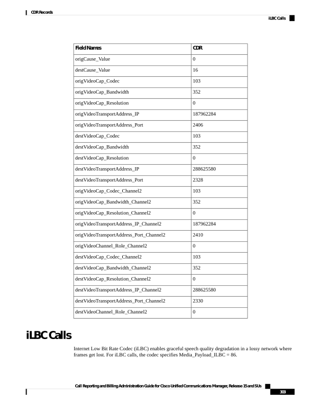
Page 316
The system adds an audio bandwidth field to the CDR for iLBC calls.
Definitions
Field Names
This integer field contains the audio bandwidth.
origMediaCap_bandwidth
This integer field contains the audio bandwidth.
destMediaCap_bandwidth
The system populates the bandwidth fields based on the following table:
Bandwidth
Codec
64
G711Alaw64k
56
G711Alaw56k
64
G711mu-law64k
56
G711mu-law56k
64
G722 64k
56
G722 56k
48
G722 48k
7
G7231
16
G728
8
G729
8
G729AnnexA
0
Is11172AudioCap
0
Is13818AudioCap
8
G729AnnexB
8
G729AnnexAwAnnexB
13
GSM Full Rate
7
GSM Half Rate
13
GSM Enhanced Full Rate
256
Wideband 256K
64
Data 64k
56
Data 56k
32
G7221 32K
24
G7221 24K
Call Reporting and Billing Administration Guide for Cisco Unified Communications Manager, Release 15 and SUs
304
CDR Records
iLBC Calls
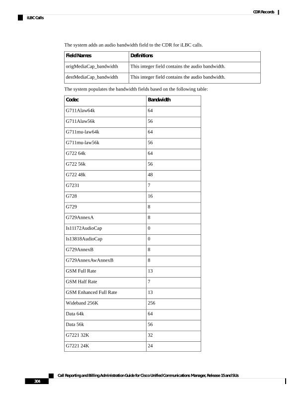
Page 317
Bandwidth
Codec
256
AAC-LD (mpeg4-generic)
128
AAC-LD (MP4A-LATM) 128K
64
AAC-LD (MP4A-LATM) 64K
56
AAC-LD (MP4A-LATM) 56K
48
AAC-LD (MP4A-LATM) 48K
32
AAC-LD (MP4A-LATM) 32K
24
AAC-LD (MP4A-LATM) 24K
13
GSM
15 or 13
iLBC
32
iSAC
8
XV150 MR 729A
8
NSE VBD 729A
iLBC Call CDR Example
This example applies to a call with iLBC codec.
iLBC CDR
Field Names
121
globalCallID_callId
101
origLegCallIdentifier
102
destLegIdentifier
51234
callingPartyNumber
57890
originalCalledPartyNumber
57890
finalCalledPartyNumber
57890
lastRedirectDn
0
origCause_Value
16
dest_CauseValue
86
origMediaCap_payloadCapability
15
origMediaCap_Bandwidth
86
destMediaCap_payloadCapability
Call Reporting and Billing Administration Guide for Cisco Unified Communications Manager, Release 15 and SUs
305
CDR Records
iLBC Calls
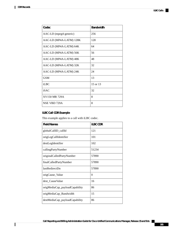
Page 318
iLBC CDR
Field Names
15
destMediaCap_Bandwidth
Intercompany Media Engine
Successful IME Calls
A call is made to PSTN. The gateway has it in the learned IME route and the call is extended to IME trunk.
Call is successfully routed out through IME trunk.
CDR
Field Names
3
globalCallID_callId
300
origLegCallIdentifier
301
destLegIdentifier
2001
callingPartyNumber
9728134987
originalCalledPartyNumber
30
lastRedirectRedirectOnBehalfOf
0
lastRedirectRedirectReason
10
duration
Failed IME Calls Due to IME Trunk Rejection
A call is made to PSTN. The gateway has it in the learned IME route and the call is extended to IME trunk.
The IME trunk rejects the call, and the call treatment does not cause the call to be redirected to the PSTN, so
the call gets rejected. Depending on the reason of IME trunk reject, different lastRedirectRedirectReason can
be reported.
CDR
Field Names
3
globalCallID_callId
300
origLegCallIdentifier
301
destLegIdentifier
2001
callingPartyNumber
9728134987
originalCalledPartyNumber
30
origTerminationOnBehalfOf
30
lastRedirectRedirectOnBehalfOf
Call Reporting and Billing Administration Guide for Cisco Unified Communications Manager, Release 15 and SUs
306
CDR Records
Intercompany Media Engine
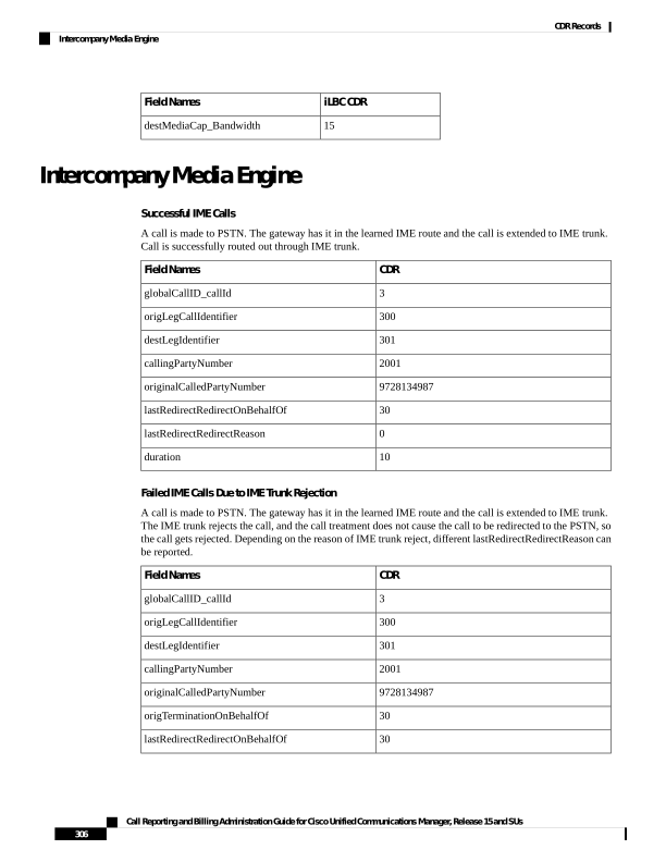
Page 319
CDR
Field Names
496 OR 512 OR 528 OR 544 OR 560 OR 576 OR
592 OR 608 OR 624 OR 640 OR 656 OR 672 OR
688 OR 704
lastRedirectRedirectReason
31
origCause_Value
0
duration
IME Calls Redirected to PSTN Due to IME Trunk Rejection
A call is made to PSTN. The gateway has it in the learned IME route and the call is extended to IME trunk.
The IME Trunk rejects the call, and the call treatment DOES cause the call to be redirected to the PSTN, so
the call gets rejected. Depending on reason of IME trunk reject, different lastRedirectRedirectReason can be
reported.
CDR
Field Names
3
globalCallID_callId
300
origLegCallIdentifier
301
destLegIdentifier
2001
callingPartyNumber
9728134987
originalCalledPartyNumber
30
lastRedirectRedirectOnBehalfOf
496 OR 512 OR 528 OR 544 OR 560 OR 576 OR
592 OR 608 OR 624 OR 640 OR 656 OR 672 OR
688 OR 704
lastRedirectRedirectReason
10
duration
IME Call Successfully Routed Out Through IME Trunk, Call Fallback to PSTN Due to Poor QoS
A call is made to PSTN. The gateway has it in the learned IME route and the call is extended to IME trunk.
Call is routed out through IME trunk. Bad QoS later discovered and call falls back to PSTN.
Two CDRs are generated in this case; one for the IME call and one for fallback to PSTN call.
Table 95: For IME call
CDR
Field Names
3
globalCallID_callId
300
origLegCallIdentifier
301
destLegIdentifier
2001
callingPartyNumber
Call Reporting and Billing Administration Guide for Cisco Unified Communications Manager, Release 15 and SUs
307
CDR Records
Intercompany Media Engine
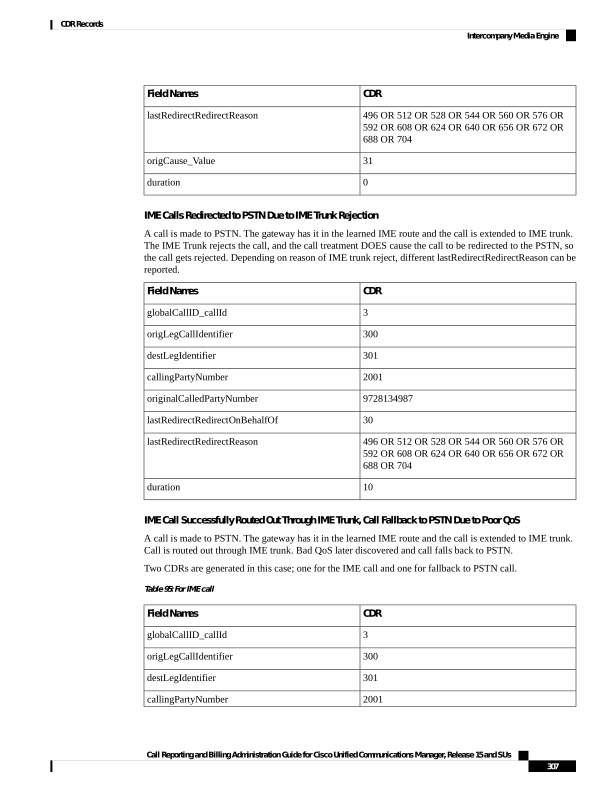
Page 320
CDR
Field Names
9728134987
originalCalledPartyNumber
30
OrigTerminationOnBehalfOf
30
lastRedirectRedirectOnBehalfOf
132
origCause_value
5
duration
Table 96: For Fallback to PSTN Call
CDR
Field Names
3
globalCallID_callId
300
origLegCallIdentifier
301
destLegIdentifier
2001
callingPartyNumber
9728134987
originalCalledPartyNumber
31
lastRedirectRedirectOnBehalfOf
31
joinOnBehalfOf
722
lastRedirectRedirectReason
5
duration
Clear the PSTN Failback Call Case 1
A call is made to PSTN. The gateway has it in the learned IME route and the call is extended to IME trunk.
Call is routed out through IME trunk. Bad QoS is discovered later and fall back initiated to PSTN. Call is
rejected by PSTN gateway. Call is intercepted by Fallback Manager which clears the call. IME call remains
untouched.
Two CDRs are generated in this case; one for the IME call and one for fallback to PSTN call.
Table 97: For IME Call
CDR
Field Names
3
globalCallID_callId
300
origLegCallIdentifier
301
destLegIdentifier
2001
callingPartyNumber
Call Reporting and Billing Administration Guide for Cisco Unified Communications Manager, Release 15 and SUs
308
CDR Records
Intercompany Media Engine
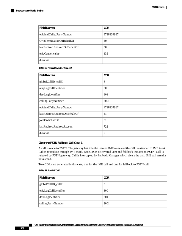
Page 321
CDR
Field Names
9728134987
originalCalledPartyNumber
30
lastRedirectRedirectOnBehalfOf
0
lastRedirectRedirectReason
5
duration
Table 98: For Fallback to PSTN Call
CDR
Field Names
3
globalCallID_callId
300
origLegCallIdentifier
301
destLegIdentifier
2001
callingPartyNumber
9728134987
originalCalledPartyNumber
31
OrigTerminationOnBehalfOf
Existing PSTN GW cause codes
origCause_value
0
duration
Clear the PSTN Failback Call Case 2
A call is made to PSTN. The gateway has it in the learned IME route and the call is extended to IME trunk.
Call is routed out through IME trunk. Bad QoS is discovered later and fall back initiated to PSTN. Cannot
find link to IME call. Call is intercepted by Fallback Manager which clears the call. IME call remains untouched.
Two CDRs are generated in this case; one for the IME call and one for fallback to PSTN call.
Table 99: For IME Call
CDR
Field Names
3
globalCallID_callId
300
origLegCallIdentifier
301
destLegIdentifier
2001
callingPartyNumber
9728134987
originalCalledPartyNumber
30
lastRedirectRedirectOnBehalfOf
0
lastRedirectRedirectReason
Call Reporting and Billing Administration Guide for Cisco Unified Communications Manager, Release 15 and SUs
309
CDR Records
Intercompany Media Engine
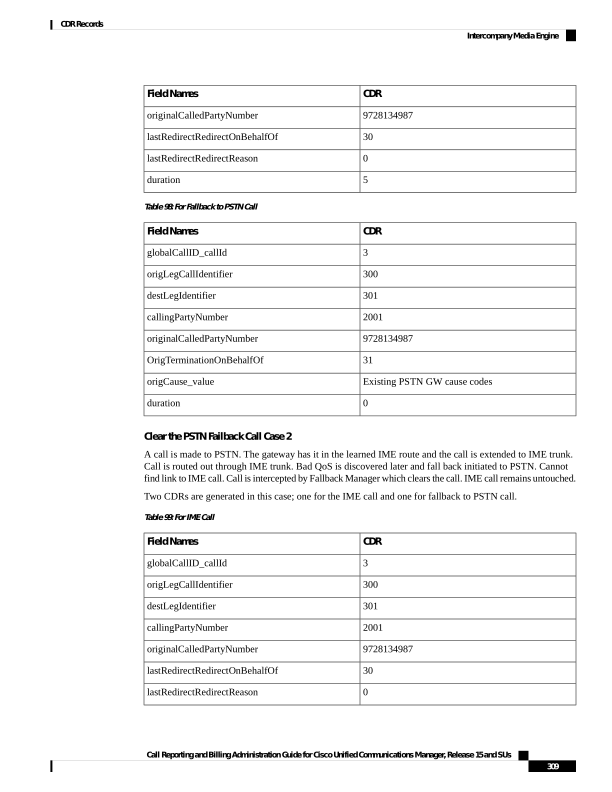
Page 322
CDR
Field Names
5
duration
Table 100: For Fallback to PSTN Call
CDR
Field Names
3
globalCallID_callId
300
origLegCallIdentifier
301
destLegIdentifier
2001
callingPartyNumber
9728134987
originalCalledPartyNumber
31
OrigTerminationOnBehalfOf
133 OR 134 OR existing cause codes
origCause_value
0
duration
Immediate Divert (to Voice-Messaging System)
Immediate Divert (IDivert) gets invoked in three different call states:
• You can invoke the IDivert feature while the incoming call is ringing. The CDR for the ringing case acts
very similar to call forwarding, but the origCalledPartyRedirectOnBehalfOf and the
lastRedirectRedirectOnBehalfOf fields specify Immediate Divert = 14.
• You can invoke the IDivert feature while the call is connected or on hold. These scenarios generate two
CDRs. Both CDRs have the same globalCallID_CallId field. The first CDR applies to the original
connection, and the second CDR applies to the call redirected to the voice-messaging system. The first
call has the origTerminationOnBehalfOf and destTerminationOnBehalfOf fields set to Immediate
Divert = 14.
• The call that gets redirected to the voice-messaging system has the origCalledPartyRedirectOnBehalfOf
and lastRedirectRedirectOnBehalfOf fields set to Immediate Divert = 14.
IDivert CDR Examples
1.
IDivert during Alerting – 40003 calls 40001, and while 40001 is ringing, 40001 presses the IDivert
button, and call diverts to the voice-messaging system 40000.
If the call gets redirected by IDivert in the Alerting state, only one CDR gets generated.
Note
Call Reporting and Billing Administration Guide for Cisco Unified Communications Manager, Release 15 and SUs
310
CDR Records
Immediate Divert (to Voice-Messaging System)

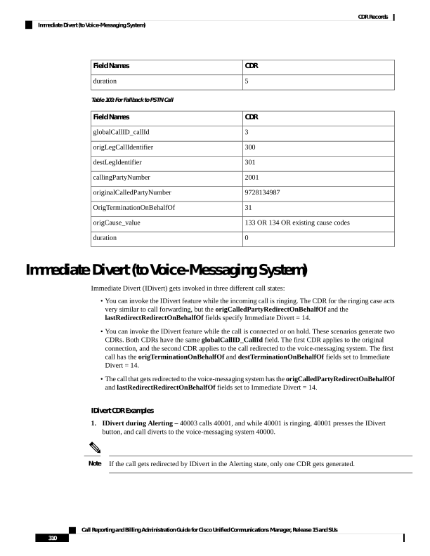
Page 323
Original call CDR
Field Names
37
globalCallID_callId
16777327
origLegCallIdentifier
16777329
destLegIdentifier
40003
callingPartyNumber
40001
origCalledPartyNumber
40000
finalCalledPartyNumber
40001
lastRedirectDn
16
origCause_Value
0
dest_CauseValue
50
origCalledPartyRedirectReason
50
lastRedirectRedirectReason
14
origCalledPartyRedirectOnBehalfOf
14
lastRedirectRedirectOnBehalfOf
14
joinOnBehalfOf
2.
IDivert during Connect – 40003 calls 40001, and 40001 answers the call. 40001 decides to divert the
caller to the voice-messaging system and presses the IDivert softkey. 40003 gets diverted to the
voice-messaging system 40000.
Because the call gets connected before the redirect, two CDRs get generated: one for the original connected
call, and another for the call that is diverted to the voice-messaging system.
Diverted Call CDR
Original Connected Call CDR
Field Names
38
38
globalCallID_callId
16777330
16777330
origLegCallIdentifier
16777332
16777331
destLegIdentifier
40003
40003
callingPartyNumber
40001
40001
origCalledPartyNumber
40000
40001
finalCalledPartyNumber
40001
40001
lastRedirectDn
16
0
origCause_Value
0
0
dest_CauseValue
Call Reporting and Billing Administration Guide for Cisco Unified Communications Manager, Release 15 and SUs
311
CDR Records
Immediate Divert (to Voice-Messaging System)
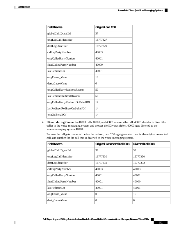
Page 324
Diverted Call CDR
Original Connected Call CDR
Field Names
50
0
origCalledPartyRedirectReason
50
0
lastRedirectRedirectReason
14
origCalledPartyRedirectOnBehalfOf
14
lastRedirectRedirectOnBehalfOf
14
14
origTerminationOnBehalfOf
12
14
destTerminationOnBehalfOf
14
joinOnBehalfOf
IMS Application Server
1.
IMS A with calls IMS B through Unified Communications Manager
The incoming invite to Unified Communications Manager contains:
Icid: 5802170000010000000000A85552590A (say, PCV1) and orig_ioi: rcdn-85.swyan.open-ims.test
(say, IOI_1).
The INVITE from the Unified Communications Manager to IMS B has the same icid as
5802170000010000000000A85552590A (PCV1), orig_ioi as rcdn-85.swyan.open-ims.test (IOI_1).
2.
When B answers, 200 OK to Unified Communications Manager has icid as
5802170000010000000000A85552590A (PCV1), orig_ioi as rcdn-85.swyan.open-ims.test (IOI_1), and
term_ioi, rcdn-86.swyan.open-ims.test (IOI_2). There could be extra fields with this 200 OK.
3.
The 200 OK from Unified Communications Manager to IMS A has icid
5802170000010000000000A85552590A (PCV1), orig_ioi as rcdn-85.swyan.open-ims.test (IOI_1), and
term_ioi as rcdn-86.swyan.open-ims.test (IOI_2). The extra fields in the 200 OK will be passed to IMS
A.
Side B
Side A
CDR
term_ioi
orig_ioi
icid
term_ioi
orig_ioi
icid
parties
IOI_2
IOI_1
PCV1
IOI_2
IOI_1
PCV1
A-B
CDR
Fields Names
3
globalCallID_callId
300
origLegCallIdentifier
301
destLegIdentifier
CUCM_ISC_TRUNK1
origDeviceName
Call Reporting and Billing Administration Guide for Cisco Unified Communications Manager, Release 15 and SUs
312
CDR Records
IMS Application Server
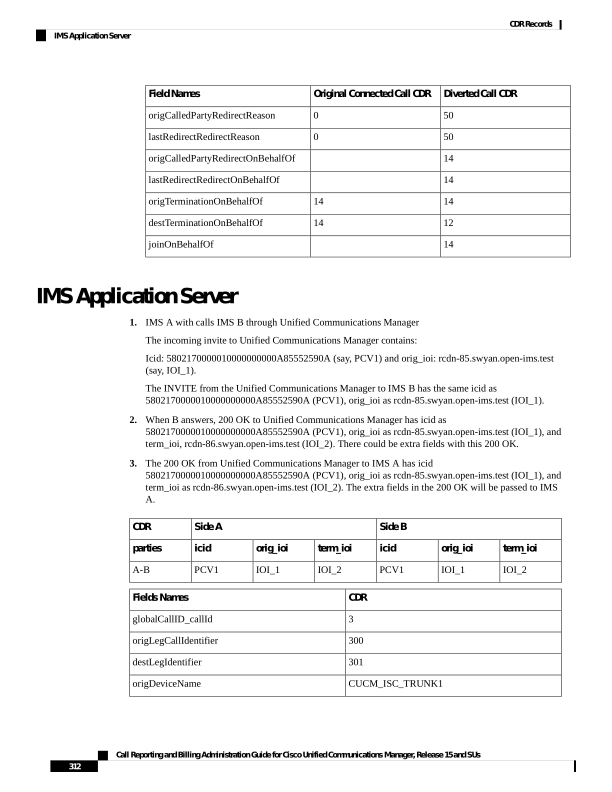
Page 325
CDR
Fields Names
CUCM_ISC_TRUNK2
destDeviceName
5802170000010000000000A85552590A
IncomingICID
rcdn-85.swyan.open-ims.test
IncomingOrigIOI
rcdn-86.swyan.open-ims.test
IncomingTermIOI
5802170000010000000000A85552590A
OutgoingICID
rcdn-85.swyan.open-ims.test
OutgoingOrigIOI
rcdn-86.swyan.open-ims.test
OutgoingTermIOI
Intercom Calls
The Intercom feature provides one-way audio; therefore, the CDR reflects one-way audio. For talk-back
intercom, two-way audio exists, and the CDR reflects two-way audio.
The Intercom feature requires a partition (intercom partition), and existing CDR partition fields get used to
identify intercom calls.
The following two examples show CDRs for intercom.
Intercom CDR Examples
1.
Whisper Intercom - Phone 20000 invokes the intercom. The configured intercom partition name specifies
“Intercom.”
Original Call CDR
Field Names
1111000
globalCallID_callId
21822467
origLegCallIdentifier
21822468
destLegIdentifier
20000
callingPartyNumber
20001
originalCalledPartyNumber
20001
finalCalledPartyNumber
16
origCause_Value
0
dest_CauseValue
0
origMediaTransportAddress_IP
0
origMediaTransportAddress_Port
-47446006
destMediaTransportAddress_IP
Call Reporting and Billing Administration Guide for Cisco Unified Communications Manager, Release 15 and SUs
313
CDR Records
Intercom Calls
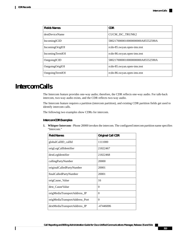
Page 326
Original Call CDR
Field Names
28480
destMediaTransportAddress_Port
Intercom
origCalledPartyNumberPartition
Intercom
callingPartyNumberPartition
Intercom
finalCalledPartyNumberPartition
5
duration
2.
Talk-Back Intercom - Phone 20000 presses the intercom button. 20001 invokes Talk-Back and talks to
20000. The configured intercom partition name specifies “Intercom.”
Original Call CDR
Field Names
1111000
globalCallID_callId
21822469
origLegCallIdentifier
21822470
destLegIdentifier
20000
callingPartyNumber
20001
originalCalledPartyNumber
20001
finalCalledPartyNumber
16
origCause_Value
0
dest_CauseValue
-131332086
origMediaTransportAddress_IP
29458
origMediaTransportAddress_Port
-47446006
destMediaTransportAddress_IP
29164
destMediaTransportAddress_Port
Intercom
origCalledPartyNumberPartition
Intercom
callingPartyNumberPartition
Intercom
finalCalledPartyNumberPartition
5
duration
IPv6 Calls
Unified Communications Manager supports IPv6 in this release. There are two new fields in the CDR for this
feature:
Call Reporting and Billing Administration Guide for Cisco Unified Communications Manager, Release 15 and SUs
314
CDR Records
IPv6 Calls
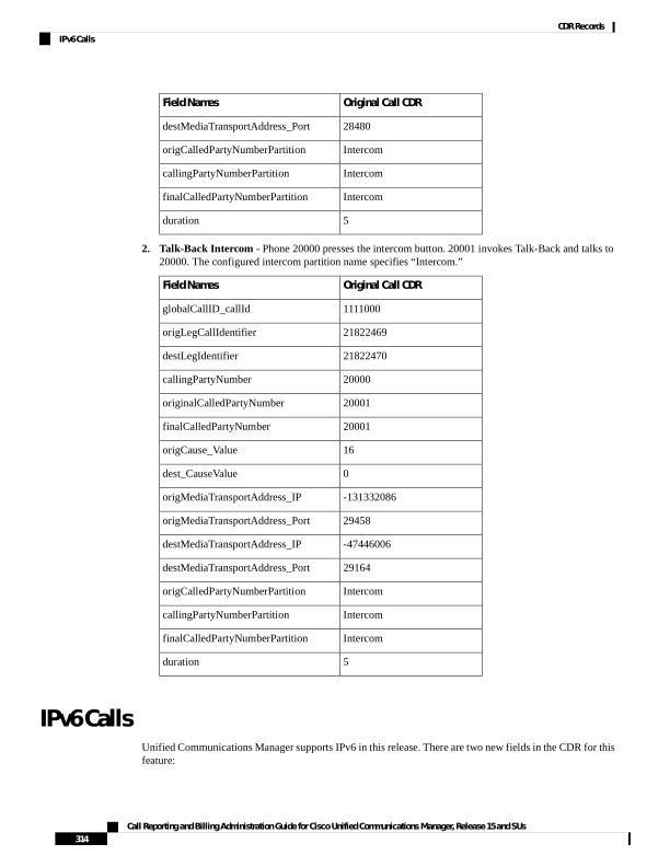
Page 327
• origIpv4v6Addr—This field identifies the IP address of the device that originates the call signaling.
The field can be in either IPv4 or IPv6 format depending on the IP address type that gets used for the
call.
• destIpv4v6Addr—This field identifies the IP address of the device that terminates the call signaling.
The field can be in either IPv4 or IPv6 format depending on the IP address type that gets used for the
call.
The following CDR examples display IPv6 with successful and unsuccessful calls.
Successful Calls
1.
A talks to B; A hangs up. A is configured as v4_only and B is configured as v4_only. The new fields
origIpv4v6Addr and destIpv4v6Addr get populated with the format of their respective v4 addresses.
Values
Field Names
1
globalCallID_callId
100
origLegCallIdentifier
101
destLegIdentifier
2001
callingPartyNumber
2309
originalCalledPartyNumber
2309
finalCalledPartyNumber
2309
lastRedirectDn
352737802
origIpAddr
1878566390
destIpAddr
10.90.6.21
origIpv4v6Addr
10.90.7.144
destIpv4v6Addr
60
duration
2.
A talks to B; A hangs up. A is configured as v6_only and B is configured as v6_only. The new fields
origIpv4v6Addr anddestIpv4v6Addr get populated with the format of their respective v6 addresses.
Values
Field Names
1
globalCallID_callId
100
origLegCallIdentifier
101
destLegIdentifier
2001
callingPartyNumber
2309
originalCalledPartyNumber
Call Reporting and Billing Administration Guide for Cisco Unified Communications Manager, Release 15 and SUs
315
CDR Records
IPv6 Calls
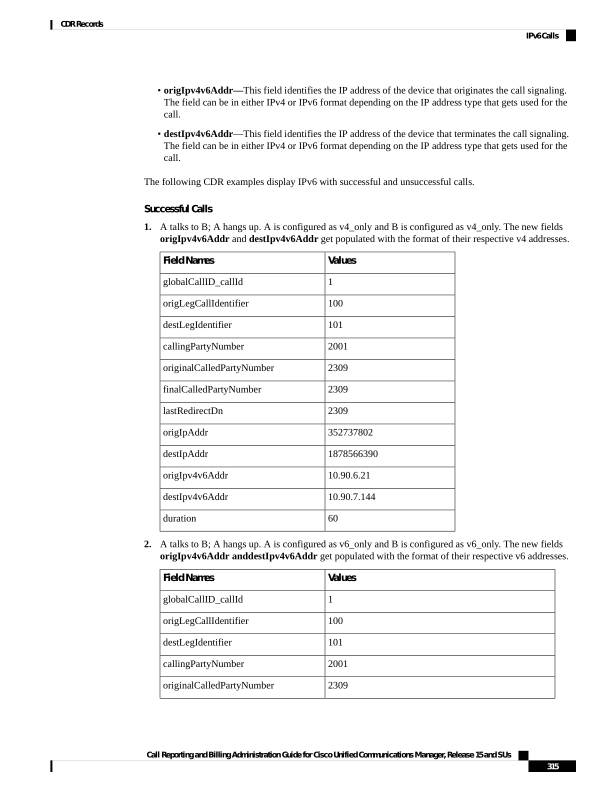
Page 328
Values
Field Names
2309
finalCalledPartyNumber
2309
lastRedirectDn
0
origIpAddr
0
destIpAddr
2001:fecd:ba23:cd1f:dcb1:1010:9234:40881
origIpv4v6Addr
2001:420:1e00:e5:217:8ff:fe5c:2fa9
destIpv4v6Addr
60
duration
3.
A talks to B; A hangs up. A is configured as v4_only and B is configured as v6_only. The new fields
origIpv4v6Addr and destIpv4v6Addr get populated with the format of their respective v4/v6 addresses.
Values
Field Names
1
globalCallID_callId
100
origLegCallIdentifier
101
destLegIdentifier
2001
callingPartyNumber
2309
originalCalledPartyNumber
2309
finalCalledPartyNumber
2309
lastRedirectDn
352737802
origIpAddr
-1878566390
destIpAddr
10.90.6.21
origIpv4v6Addr
10.90.7.144
destIpv4v6Addr
60
duration
4.
A talks to B; A hangs up. A is configured as v4_v6 and B is configured as v4_only. In this case, media
negotiates v4. The new fields origIpv4v6Addr and destIpv4v6Addr get populated with the format of
their respective v4 addresses.
Values
Field Names
1
globalCallID_callId
100
origLegCallIdentifier
101
destLegIdentifier
Call Reporting and Billing Administration Guide for Cisco Unified Communications Manager, Release 15 and SUs
316
CDR Records
IPv6 Calls
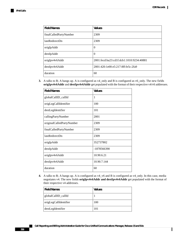
Page 329
Values
Field Names
2001
callingPartyNumber
2309
originalCalledPartyNumber
2309
finalCalledPartyNumber
2309
lastRedirectDn
352737802
origIpAddr
-1878566390
destIpAddr
10.90.6.21
origIpv4v6Addr
10.90.7.144
destIpv4v6Addr
60
duration
5.
A talks to B; A hangs up. A is configured as v4_v6 and B is configured as v6_only. In this case, media
negotiates v6. The new fields origIpv4v6Addr and destIpv4v6Addr get populated with the format of
their respective v6 addresses.
Values
Field Names
1
globalCallID_callId
100
origLegCallIdentifier
101
destLegIdentifier
2001
callingPartyNumber
2309
originalCalledPartyNumber
2309
finalCalledPartyNumber
2309
lastRedirectDn
352737802
origIpAddr
0
destIpAddr
2001:fecd:ba23:cd1f:dcb1:1010:9234:4088
origIpv4v6Addr
2001:420:1e00:e5:217:8ff:fe5c:2fa9
destIpv4v6Addr
60
duration
Unsuccessful Calls
1.
A calls B; A abandons the call. A is configured as v4_only and B is configured as v6_only. The new field
origIpv4v6Addr gets populated with the format of its v4 address. The new field destIpv4v6Addr does
not get populated.
Call Reporting and Billing Administration Guide for Cisco Unified Communications Manager, Release 15 and SUs
317
CDR Records
IPv6 Calls
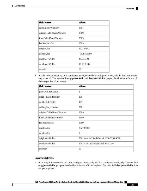
Page 330
Values
Field Names
1
globalCallID_callId
100
origLegCallIdentifier
101
destLegIdentifier
2001
callingPartyNumber
2309
originalCalledPartyNumber
2309
finalCalledPartyNumber
2309
lastRedirectDn
352737802
origIpAddr
-569419254
destIpAddr
10.90.15.222
origIpv4v6Addr
destIpv4v6Addr
0
duration
2.
A calls B; the call fails. A is configured as v6_only and B is configured as v4_v6. The new field
origIpv4v6Addr gets populated with the format of its v6 address. The new field destIpv4v6Addr does
not get populated in this case.
Values
Field Names
1
globalCallID_callId
100
origLegCallIdentifier
101
destLegIdentifier
2001
callingPartyNumber
2309
originalCalledPartyNumber
2309
finalCalledPartyNumber
2309
lastRedirectDn
0
origIpAddr
0
destIpAddr
2001:fecd:ba23:cd1f:dcb1:1010:9234:4088
origIpv4v6Addr
destIpv4v6Addr
0
duration
Call Reporting and Billing Administration Guide for Cisco Unified Communications Manager, Release 15 and SUs
318
CDR Records
IPv6 Calls
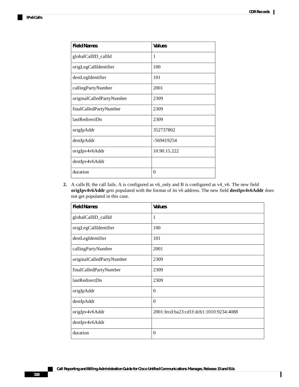
Page 331
Legacy Call Pickup
Legacy Call Pickup calls act similar to forwarded calls. Legacy Call Pickup uses the redirect call control
primitive like call forwarding. Some of the important CDR fields for Legacy Call Pickup calls follow:
• The originalCallPartyNumber field contains the number of the original called party.
• The finalCalledPartyNumber field specifies the number of the party that picks up the call.
• The lastRedirectDn field specifies the number that rings when the call gets picked up.
• The origCalledPartyRedirectReason field specifies the reason that the call gets redirected the first
time. For call pickup calls, this field can contain Call Pickup = 5.
• The lastRedirectRedirectReason field specifies the reason that the call gets redirected the last time.
For call pickup, this field can contain Call Pickup = 5.
• The origCalledPartyRedirectOnBehalfOf field identifies which feature redirects the call for the first
redirect. For call pickup, this field specifies Pickup = 16.
• The lastRedirectRedirectOnBehalfOf field identifies which feature redirects the call for the last redirect.
For call pickup, this field specifies Pickup = 16.
Legacy Call Pickup CDR Example
Call from the PSTN to extension 2001; 2001 and 2002 exist in the same pickup group. 2002 picks up the call
that rings on 2001. 2002 answers the call, and the call connects between the PSTN caller and 2002. They talk
for 2 minutes.
CDR
Field Names
22
globalCallID_callId
1
origLegCallIdentifier
2
destLegIdentifier
9728134987
callingPartyNumber
2001
originalCalledPartyNumber
2002
finalCalledPartyNumber
2001
lastRedirectDn
0
origCause_Value
16
dest_CauseValue
0
origCalledPartyRedirectReason
5
lastRedirectRedirectReason
16
origCalledPartyRedirectOnBehalfOf
Call Reporting and Billing Administration Guide for Cisco Unified Communications Manager, Release 15 and SUs
319
CDR Records
Legacy Call Pickup
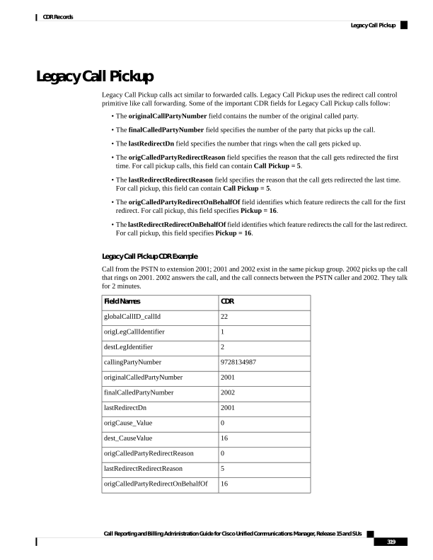
Page 332
CDR
Field Names
16
lastRedirectRedirectOnBehalfOf
120
duration
Local Route Groups and Called Party Transformation
In this release, Unified Communications Manager supports the new feature, local route groups and called
party transformation. The device reports the Called Party Number that it outpulsed back to Call Control only
if called party transformation occurs. This action gets recorded in the CDR in the new field
outpulsedCalledPartyNumber.
Local Route Groups and Called Party Normalization CDR Example
A call gets placed from an enterprise phone in Dallas to the PSTN; the dialed number specifies 9.5551212.
The translation causes the called party number to take the digits as dialed by the originator, discard PreDot
and add the Prefix +1 214.
The finalCalledPartyNumber in the CDR comprises the globally unique E.164 string +12145551212.
If a San Jose gateway gets selected, it transforms the global string +1 214 555 1212 into 12145551212, and
if a Dallas gateway gets selected, the global string gets transformed into 2145551212.
The device returns this global string to Call Control as the outpulsedCalledPartyNumber; it gets recorded
in the CDR.
The following CDR gets created if the San Jose gateway gets selected.
Values
Field Names
1
globalCallID_callId
100
origLegCallIdentifier
101
destLegIdentifier
2001
callingPartyNumber
+12145551212
originalCalledPartyNumber
2309
finalCalledPartyNumber
2309
lastRedirectDn
16
origCause_Value
0
dest_CauseValue
60
duration
12145551212
outpulsedCalledPartyNumber
The following CDR gets created if the Dallas gateway gets selected.
Call Reporting and Billing Administration Guide for Cisco Unified Communications Manager, Release 15 and SUs
320
CDR Records
Local Route Groups and Called Party Transformation
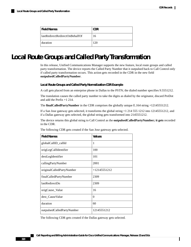
Page 333
Values
Field Names
1
globalCallID_callId
100
origLegCallIdentifier
101
destLegIdentifier
2001
callingPartyNumber
+12145551212
originalCalledPartyNumber
+12145551212
finalCalledPartyNumber
+12145551212
lastRedirectDn
16
origCause_Value
0
dest_CauseValue
60
duration
2145551212
outpulsedCalledPartyNumber
Logical Partitioning Calls
The Telecom Regulatory Authority of India (TRAI) requires that voice traffic over an enterprise data network
and a PSTN network remain separate. The logical partitioning feature ensures that a single system can be used
to support both types of calls as long as calls that pass through a PSTN gateway can never directly connect
to a VoIP phone or VoIP PSTN gateway in another geographic location (geolocation).
CDR Example for Call Termination Cause Code CCM_SIP_424_BAD_LOCATION_INFO
A SIP trunk call goes from cluster1 to cluster2. The call contains a geolocation header but does not include
an XML location. Cluster2 releases the call with a SIP Status code of 424 (bad location information [decimal
value = 419430421]).
Cause code CCM_SIP_424_BAD_LOCATION_INFO gets logged for calls that are cleared because of bad
location information by the SIP trunk on the Unified Communications Manager. The remote endpoint on the
SIP trunk can send the 424 SIP Status code for cases when the geolocation information is bad for some of the
following reasons:
• The geolocation header indicates the inclusion of PIDF-LO, but the message body does not carry this
information.
• The geolocation header has a CID header that refers to a URL, but no corresponding Content-IP header
with the same URL exists.
• The geolocation header has a URL other than the CID header (that is a SIP, or SIPS URL).
Refer to additional CDR examples for more information on other call termination cause codes.
Call Reporting and Billing Administration Guide for Cisco Unified Communications Manager, Release 15 and SUs
321
CDR Records
Logical Partitioning Calls
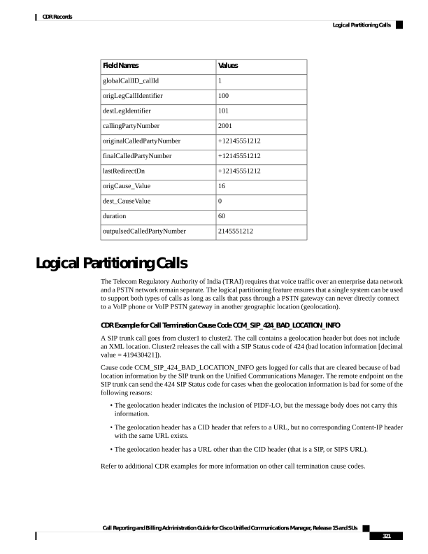
Page 334
Values
Field Names
1
globalCallID_callId
100
origLegCallIdentifier
101
destLegIdentifier
2001
callingPartyNumber
9900
originalCalledPartyNumber
9900
finalCalledPartyNumber
9900
lastRedirectDn
0
origCause_Value
419430421
dest_CauseValue
0
duration
CDR Example for Call Termination Cause Code 503
Call 82291002 from cluster1 gets call-forwarded to the PSTN 41549901. A call occurs from cluster2 from
DN 89224001 to cluster1 DN 82291002. The call gets denied because of logical partitioning with a call
termination cause code of CCM_SIP_503_SERVICE_UNAVAIL_SER_OPTION_NOAVAIL [decimal value
of -1493172161]) for the dest_CauseValue.
Cause code CCM_SIP_503_SERVICE_UNAVAIL_SER_OPTION_NOAVAIL gets logged for calls that get
cleared because of restricted logical partitioning policy checks during the call establishment phase (basic call,
call forwarding, call pickup, call park, meet-me conferences, and so forth). Refer to additional CDR examples
for more information on other call termination cause codes.
Values
Field Names
1
globalCallID_callId
100
origLegCallIdentifier
101
destLegIdentifier
89224001
callingPartyNumber
82291002
originalCalledPartyNumber
41549901
finalCalledPartyNumber
82291002
lastRedirectDn
0
origCause_Value
-1493172161
dest_CauseValue
0
duration
Call Reporting and Billing Administration Guide for Cisco Unified Communications Manager, Release 15 and SUs
322
CDR Records
Logical Partitioning Calls
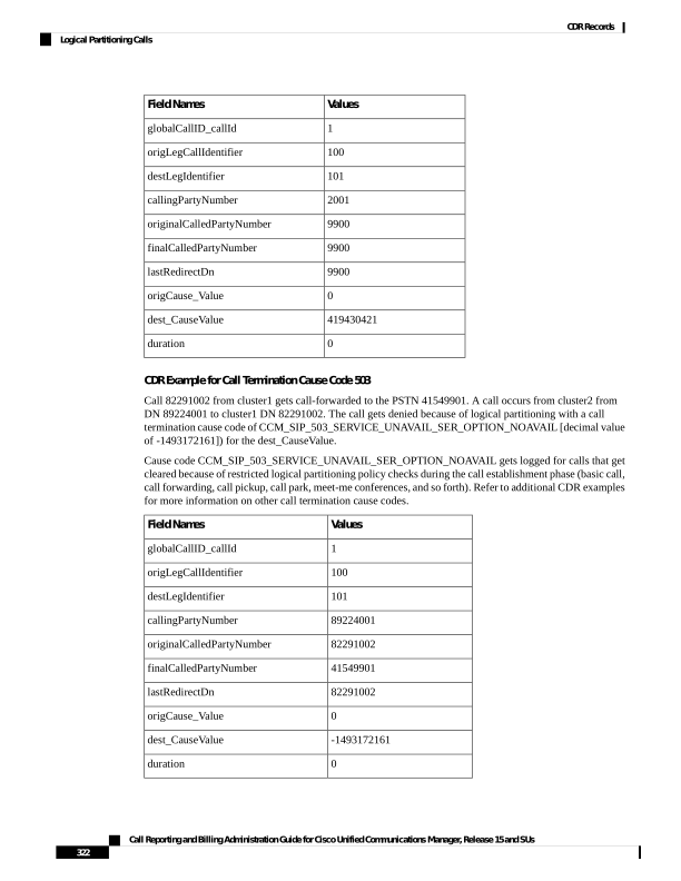
Page 335
Malicious Calls
When a call gets identified as a malicious call (button press), the local Unified Communications Manager
network flags the call. The Comment field flags the malicious call.
Malicious Calls CDR Example
The following table contains an example CDR of a customer call that gets marked as malicious.
Comment
Dest
Cause
Orig
Cause
Original
Called
Partition
Original
Called Party
Calling
Partition
Calling Party
“callFlag=MALICIOUS”
16
0
ACNTS
5555
CUST
9728552001
Meet-Me Conferences
A meet-me conference occurs when several parties individually dial into a conference bridge at a predetermined
time.
The Cisco Secure Conference feature uses the existing callSecuredStatus field to display the highest security
status that a call reaches. For meet-me conferences, the system clears calls that try to join the conference but
do not meet the security level of the meet-me conference with a terminate cause = 58 (Bearer capability not
presently available).
Meet-Me Conference CDR Example
The following table contains an example CDR for the following scenario. 5001 specifies the dial-in number.
The conference bridge device signifies special significance to the Unified Communications Manager, and
calls to the conference bridge appear as forwarded calls; that is, UserA phones the predetermined number
(5001); the call gets forwarded to a conference bridge port. The conference bridge port appears with a special
number of the form “b0019901001.”
• User A (2001) calls into a meet-me conference bridge with the phone number 5001.
• User B (2002) calls into a meet-me conference bridge with the phone number 5001.
• User C (2003) calls into a meet-me conference bridge with the phone number 5001.
Last
Redirect
Partition
Last Redirect
Party
Final Called
Partition
Final Called
Party
Original
Called
Partition
Original
Called Party
Calling
Partition
Calling
Party
b0019901001
b0019901001
5001
Accounts
2001
A
b0019901001
b0019901001
5001
Accounts
2002
B
b0019901001
b0019901001
5001
Accounts
2003
C
Call Reporting and Billing Administration Guide for Cisco Unified Communications Manager, Release 15 and SUs
323
CDR Records
Malicious Calls
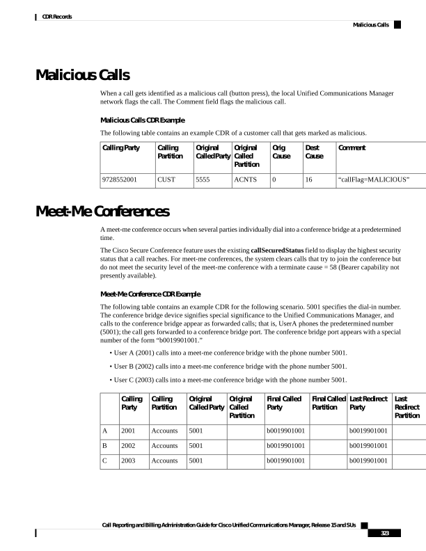
Page 336
Mobility
The following call detail record (CDR) fields apply specifically to Mobility calls. If the call does not invoke
a mobility feature, these fields remain empty:
• mobileCallingPartyNumber
• finalMobileCalledPartyNumber
• origMobileDeviceName
• destMobileDeviceName
• origMobileCallDuration
• destMobileCallDuration
• mobileCallType
The system generates a standard CDR for every call that uses the Mobility features. When a call gets split,
redirected, or joined by the Mobility feature, the corresponding OnBehalfOf code represents a new value that
is designated to Mobility. If any of the following OnBehalfOf fields has the Mobility code of 24, the CDR
has the Mobility call type:
• origCallTerminationOnBehalfOf
• destCallTerminationOnBehalfOf
• origCalledPartyRedirectOnBehalfOf
• lastRedirectRedirectOnBehalfOf
• joinOnBehalfOf
MobileCallType Values
The following table displays the field values for the mobileCallType CDR field. Cisco Analysis and Reporting
(CAR) uses the mobileCallType field to determine the CAR call type. If a single call invokes more than one
mobility feature, the value of the mobileCallType field represents the integer values added together. For
example, if a call uses the Mobile Connect feature and then invokes Hand-Out, the mobile call type will be
136 (8 + 128).
mobileCallType Value
Mobility Feature
0
Nonmobility call
1
Dial via Office Reverse Callback
2
Dial via Office Forward
4
Reroute remote destination call to enterprise
network
8
Mobile Connect
10
Interactive Voice Response
Call Reporting and Billing Administration Guide for Cisco Unified Communications Manager, Release 15 and SUs
324
CDR Records
Mobility
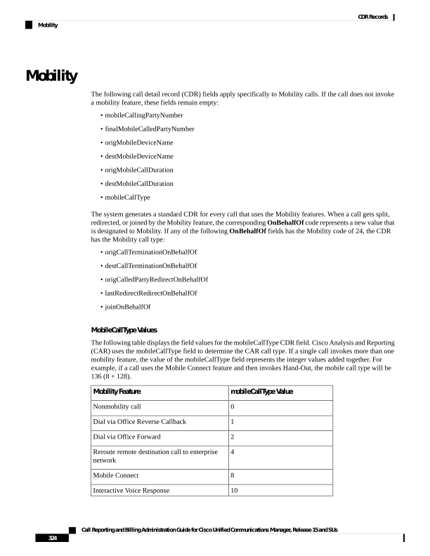
Page 337
mobileCallType Value
Mobility Feature
20
Enterprise Feature Access
40
Hand-In
80
Hand-Out
100
Redial
200
Least Cost Routing with dial-via-office reverse
callback
82
Least Cost Routing with dial-via-office forward
800
Send call to mobile
1000
Session handoff
Last Redirect Reason
In legacy deployments before 10.0, CAR uses the lastRedirectReason field to identify the mobility call type.
The following table shows the Mobility values for lastRedirectReason.
lastRedirectReason Value
Mobility Feature
303
Hand-In
319
Hand-Out
335
Mobile Connect
351
Redial
399
Interactive Voice Response
401
Dial via Office Reverse Callback
402
Enterprise Feature Access
403
Session Handoff
415
Send call to mobile
783
Reroute remote destination call to enterprise
network
Mobility CDR Examples
The following examples demonstrate how mobility features display in CDR records:
1.
Mobile phone initiates Dial via Office Reverse Callback - A mobile phone with a device name of
BOTSAU, a mobile number of 2145551234, and an enterprise number of 1000 invokes the dial-via-office
Reverse callback feature to place a call to extension 2000. The MAC address of the called device is
Call Reporting and Billing Administration Guide for Cisco Unified Communications Manager, Release 15 and SUs
325
CDR Records
Mobility
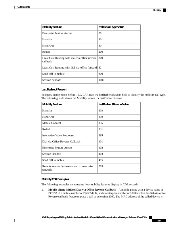
Page 338
SEP001FCAE90004. The IP address of the SIP gateway is 10.194.108.70. The total call duration is 55
seconds.
Dial via Office Reverse Callback CDR
Field
0
origCallTerminationOnBehalfOf
12
destCallTerminationOnBehalfOf
24
origCalledRedirectOnBehalfOf
24
lastRedirectOnBehalfOf
24
joinOnBehalfOf
401
origCalledPartyRedirectReason
401
lastRedirectReason
10.194.108.70
origDeviceName
SEP001FCAE9004
destDeviceName
2000
finalCalledPartyNumber
huntPilotDN
2145551234
mobileCallingPartyNumber
finalMobileCalledPartyNumber
BOTSAU
origMobileDeviceName
destMobileDeviceName
55
origMobileCallDuration
destMobileCallDuration
1
mobileCallType
2.
Mobile phone initiates Dial via Office Forward - Mobile phone 2145551234 initiates the Dial via
Office Forward feature to place a call. The mobile phone has a device name of BOTSAU and is mapped
to enterprise number 1000. The called number is extension 823006 with a device MAC address of
SEP001FCAE90004. The call crosses a SIP gateway at 10.194.108.70 and lasts for a total duration of
120 seconds.
Dial via Office Forward CDR
Field
0
origCallTerminationOnBehalfOf
12
destCallTerminationOnBehalfOf
0
origCalledRedirectOnBehalfOf
0
lastRedirectOnBehalfOf
Call Reporting and Billing Administration Guide for Cisco Unified Communications Manager, Release 15 and SUs
326
CDR Records
Mobility
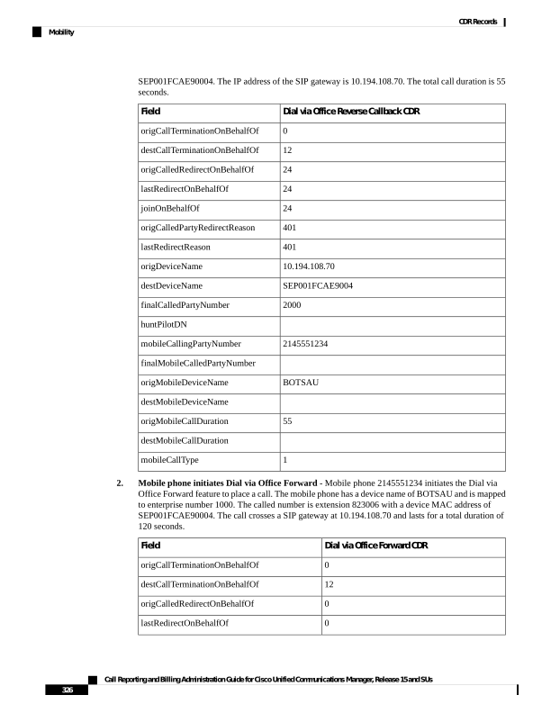
Page 339
Dial via Office Forward CDR
Field
0
joinOnBehalfOf
0
origCalledPartyRedirectReason
0
lastRedirectReason
10.194.108.70
origDeviceName
SEP001FCAE90004
destDeviceName
823006
finalCalledPartyNumber
huntPilotDN
2145551234
mobileCallingPartyNumber
finalMobileCalledPartyNumber
BOTSAU
origMobileDeviceName
destMobileDeviceName
120
origMobileCallDuration
0
destMobileCallDuration
2
mobileCallType
3.
Call to remote destination is rerouted to enterprise number - Cisco Unified IP Phone
SEP001FCAE90004, at extension 2000, dials mobile number 2145551234. The destination mobile
phone is mapped to enterprise number 1000 and has the Reroute Remote Destination Calls to Enterprise
Number service parameter enabled in Unified Communications Manager. Unified Communications
Manager reroutes the mobile call to enterprise number 1000. The call crosses SIP gateway GW_SIP
and lasts for a total duration of 60 seconds.
Reroute Remote Detination CDR
Field
0
origCallTerminationOnBehalfOf
12
destCallTerminationOnBehalfOf
24
origCalledRedirectOnBehalfOf
24
lastRedirectOnBehalfOf
0
joinOnBehalfOf
783
origCalledPartyRedirectReason
783
lastRedirectReason
SEP001FCAE90004
origDeviceName
GW_SIP
destDeviceName
Call Reporting and Billing Administration Guide for Cisco Unified Communications Manager, Release 15 and SUs
327
CDR Records
Mobility
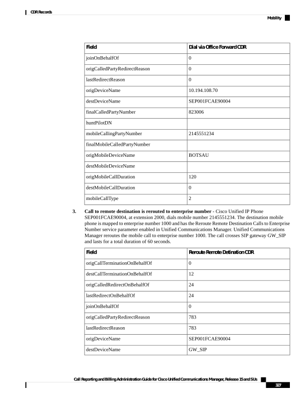
Page 340
Reroute Remote Detination CDR
Field
1000
finalCalledPartyNumber
huntPilotDN
mobileCallingPartyNumber
2145551234
finalMobileCalledPartyNumber
origMobileDeviceName
2145551234:rdp
destMobileDeviceName
0
origMobileCallDuration
60
destMobileCallDuration
4
mobileCallType
4.
Mobile phone invokes deskphone call pickup - Cisco Unified IP Phone SEP001FCAE90004 calls
extension 1000, which is shared between a desk phone and a mobile device. The mobile phone answers
the call and then hangs up, triggering the desktop pickup feature. The desktop call pickup timer runs
for about 10 seconds before expiring. After the timer expires, the call is resumed on a Wi-Fi device for
another 10 seconds.
Desktop Call Pickup CDR
Field
0
origCallTerminationOnBehalfOf
12
destCallTerminationOnBehalfOf
0
origCalledRedirectOnBehalfOf
0
lastRedirectOnBehalfOf
0
joinOnBehalfOf
0
origCalledPartyRedirectReason
0
lastRedirectReason
SEP001FCAE90004
origDeviceName
GW_SIP
destDeviceName
1000
finalCalledPartyNumber
huntPilotDN
mobileCallingPartyNumber
finalMobileCalledPartyNumber
origMobileDeviceName
Call Reporting and Billing Administration Guide for Cisco Unified Communications Manager, Release 15 and SUs
328
CDR Records
Mobility
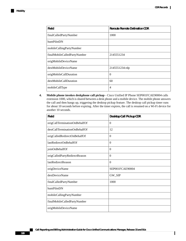
Page 341
Desktop Call Pickup CDR
Field
destMobileDeviceName
0
origMobileCallDuration
10
destMobileCallDuration
8
mobileCallType
5.
Mobile Connect Call - Single Number Reach Voicemail policy set to Timer Control - Cisco Unified
IP Phone SEP001FCAE90004, at extension 2000, calls enterprise number 1000. Mobile Connect is
invoked and both the desk phone and mobile phone ring. The mobile phone uses a mobile identity with
a device name of BOTSARAH. The Single Number Reach Voicemail policy is set to Timer Control.
The call traverses a SIP gateway and lasts for 10 minutes.
CDR
Field
0
origCallTerminationOnBehalfOf
12
destCallTerminationOnBehalfOf
0
origCalledRedirectOnBehalfOf
0
lastRedirectOnBehalfOf
0
joinOnBehalfOf
0
origCalledPartyRedirectReason
0
lastRedirectReason
SEP001FCAE90004
origDeviceName
GW_SIP
destDeviceName
1000
finalCalledPartyNumber
huntPilotDN
mobileCallingPartyNumber
2145551234
finalMobileCalledPartyNumber
origMobileDeviceName
BOTSARAH
destMobileDeviceName
0
origMobileCallDuration
10
destMobileCallDuration
8
mobileCallType
6.
Mobile Connect Call - Single Number Reach Voicemail Policy set to UserControl Mode -Cisco
Unified IP Phone SEP001FCAE91231 at enterprise number 238011 calls across a SIP gateway, GW_SIP.
Call Reporting and Billing Administration Guide for Cisco Unified Communications Manager, Release 15 and SUs
329
CDR Records
Mobility
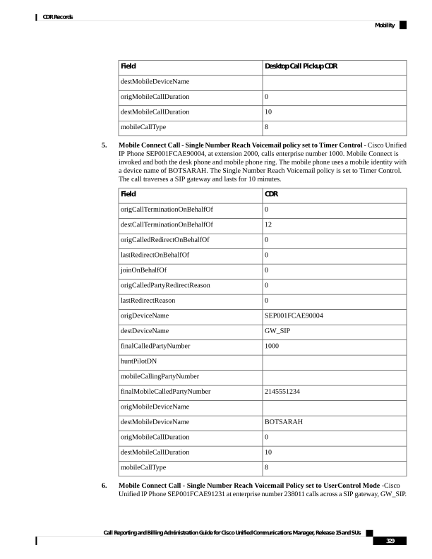
Page 342
The called party is SEP001FCEA91289, at enterprise number 238006 and mobile number 14089022179.
Three CDRs are produced.
IP Phone to Mobile
Phone
0 Duration Call
Announcement to
user
Field
12
24
24
origCallTerminationOnBehalfOf
24
24
24
destCallTerminationOnBehalfOf
24
24
24
origCalledRedirectOnBehalfOf
24
24
24
lastRedirectOnBehalfOf
24
0
0
joinOnBehalfOf
335
335
335
origCalledPartyRedirectReason
335
335
335
lastRedirectReason
SEP001FCAE91231
ParkingLotDevice
SEP001FCAE91231
origDeviceName
GW_SIP
GW_SIP
GW_SIP
destDeviceName
238006
238006
238006
finalCalledPartyNumber
huntPilotDN
mobileCallingPartyNumber
14089022179
14089022179
14089022179
finalMobileCalledPartyNumber
origMobileDeviceName
14089022179:rdp
14089022179:rdp
14089022179:rdp
destMobileDeviceName
0
0
origMobileCallDuration
6
3
destMobileCallDuration
8
8
8
mobileCallType
7.
Mobile phone makes an Enterprise Feature Access (EFA) call with two-stage dialing - Remote
destination deepak-RDP, at 4089022179 with shared-line desk phone SEP001EBE90DE95 and enterprise
number 238006, calls internal desk phone SEP001FCAE91231, at enterprise number 238011, using
Enterprise Feature Access two-stage dialing. Total call duration is 30 seconds. Two CDRs are produced:
one for the mobile phone dialing the EFA access codes into Unified Communications Manager and the
second for the mobile phone to desk phone conversation.
Mobile Phone to Desk Phone
Mobile Phone to Unified
Communications Manager
Field
12
24
origCallTerminationOnBehalfOf
24
24
destCallTerminationOnBehalfOf
Call Reporting and Billing Administration Guide for Cisco Unified Communications Manager, Release 15 and SUs
330
CDR Records
Mobility
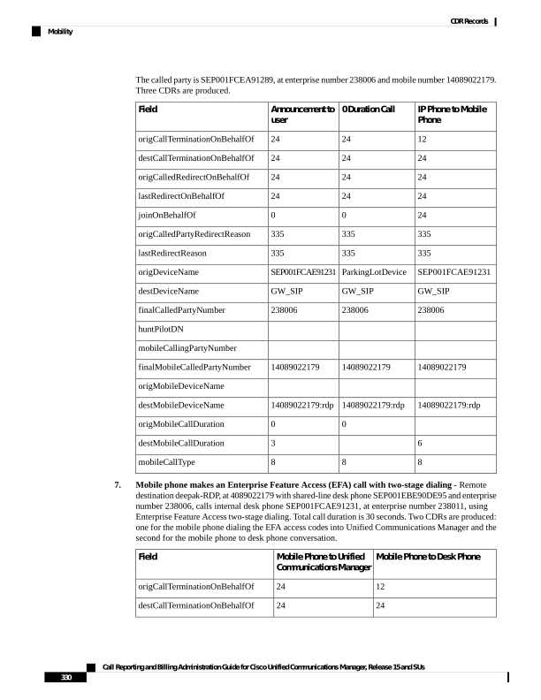
Page 343
Mobile Phone to Desk Phone
Mobile Phone to Unified
Communications Manager
Field
24
24
origCalledRedirectOnBehalfOf
24
24
lastRedirectOnBehalfOf
24
24
joinOnBehalfOf
402
402
origCalledPartyRedirectReason
402
402
lastRedirectReason
GW_SIP
GW_SIP
origDeviceName
SEP001FCAE91231
ParkingLotDevice
destDeviceName
238011
00111101001
finalCalledPartyNumber
huntPilotDN
14089022179
14089022179
mobileCallingPartyNumber
finalMobileCalledPartyNumber
14089022179:rdp
14089022179:rdp
origMobileDeviceName
destMobileDeviceName
25
5
origMobileCallDuration
0
destMobileCallDuration
32
32
mobileCallType
8.
Mobile phone makes a Mobile Voice Access call - Remote destination 4089022179, with shared line
desk phone SEP001EBE90DE95 at enterprise number 238006, uses Mobile Voice Access to call an
internal desk phone SEP00000000000002 at enterprise number 238011. The remote destination has a
remote destination profile of deepak-rdp. The call traverses SIP gateway GW_SIP and lasts for 60
seconds.
Mobile Phone to Desk Phone
Field
12
origCallTerminationOnBehalfOf
0
destCallTerminationOnBehalfOf
24
origCalledRedirectOnBehalfOf
24
lastRedirectOnBehalfOf
24
joinOnBehalfOf
399
origCalledPartyRedirectReason
399
lastRedirectReason
Call Reporting and Billing Administration Guide for Cisco Unified Communications Manager, Release 15 and SUs
331
CDR Records
Mobility
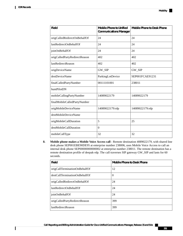
Page 344
Mobile Phone to Desk Phone
Field
GW_SIP
origDeviceName
SEP00000000000002
destDeviceName
238011
finalCalledPartyNumber
huntPilotDN
14089022179
mobileCallingPartyNumber
finalMobileCalledPartyNumber
14089022179:rdp
origMobileDeviceName
destMobileDeviceName
60
origMobileCallDuration
destMobileCallDuration
16
mobileCallType
9.
Mobility Hand-In - Cisco Unified IP Phone SEP001FCAE91231 at enterprise number 238011, calls
enterprise number 238006, which is unregistered on the VoIP side, but registered to the smartphone
TCTSAU. The mobile identity of the smartphone is 14089022179. At the beginning of the call TCTSAU
is located in a cellular network, but the device moves into Wi-Fi range and the Hand-In feature is invoked
to move the call into the enterprise. The total call duration is 85 seconds, with the called device in Wi-Fi
range for the last 30 seconds.
IP Phone to IP Phone
IP Phone to Cellular Phone
Field
12
24
origCallTerminationOnBehalfOf
24
24
destCallTerminationOnBehalfOf
0
0
origCalledRedirectOnBehalfOf
24
0
lastRedirectOnBehalfOf
24
0
joinOnBehalfOf
303
0
origCalledPartyRedirectReason
303
0
lastRedirectReason
SEP001FCAE91231
SEP001FCAE91231
origDeviceName
TCTSAU
GW_SIP
destDeviceName
238006
238006
finalCalledPartyNumber
huntPilotDN
mobileCallingPartyNumber
Call Reporting and Billing Administration Guide for Cisco Unified Communications Manager, Release 15 and SUs
332
CDR Records
Mobility
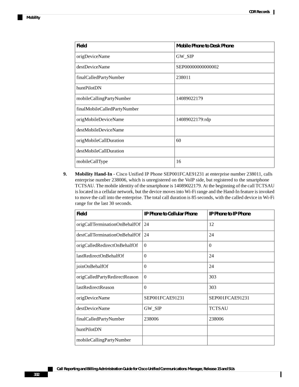
Page 345
IP Phone to IP Phone
IP Phone to Cellular Phone
Field
14089022179
finalMobileCalledPartyNumber
origMobileDeviceName
TCTSAU
destMobileDeviceName
0
0
origMobileCallDuration
55
destMobileCallDuration
72
8
mobileCallType
10.
Mobility Hand-Out - Cisco Unified IP Phone SEP001FCAE94005 at enterprise number 238011, calls
a dual-mode smartphone with a mobile identity of 14089022179, at enterprise number 238006. The
smartphone is in local Wi-Fi range when the call is answered and the two parties speak for 27 seconds.
The smartphone moves out of the enterprise network and the call is switched to the cell network, after
which the parties continue to speak for another 25 seconds.
IP Phone to Cell Network
IP Phone to IP Phone
Field
0
24
origCallTerminationOnBehalfOf
12
24
destCallTerminationOnBehalfOf
0
0
origCalledRedirectOnBehalfOf
24
0
lastRedirectOnBehalfOf
24
0
joinOnBehalfOf
0
0
origCalledPartyRedirectReason
319
0
lastRedirectReason
SEP001FCAE94005
SEP001FCAE94005
origDeviceName
GW_SIP
TCTSAU
destDeviceName
238006
238006
finalCalledPartyNumber
huntPilotDN
mobileCallingPartyNumber
14089022179
finalMobileCalledPartyNumber
origMobileDeviceName
TCTSAU
destMobileDeviceName
0
0
origMobileCallDuration
23
0
destMobileCallDuration
Call Reporting and Billing Administration Guide for Cisco Unified Communications Manager, Release 15 and SUs
333
CDR Records
Mobility
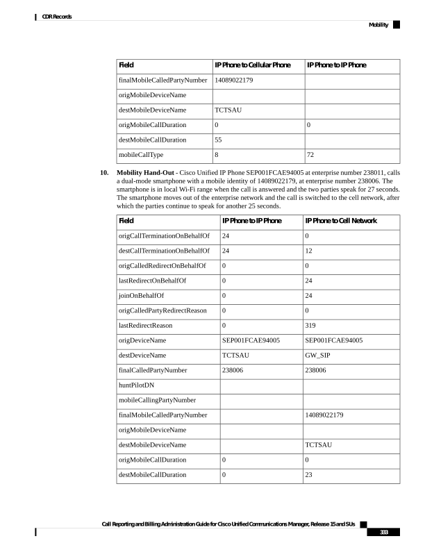
Page 346
IP Phone to Cell Network
IP Phone to IP Phone
Field
128
0
mobileCallType
11.
Mobile phone invokes Least Cost Routing Hand-Out using Dial via Office Reverse Callback - A
dual-mode phone, BOTSAU, with a mobile identity of 14089022179, is within the enterprise wifi
network and registered to enterprise number 238006. The phone invokes Dial via Office Reverse Callback
(DVOR) using least cost routing to call enterprise number 238011. The two parties speak for 25 seconds,
but the mobile phone moves out of Wi-Fi range, triggering the handout feature to the cellular network.
On the cell network, the two parties speak for another 35 seconds.
Mobile phone to IP
phone
IP phone to IP phone
DVOR callback
Field
0
24
24
origCallTerminationOnBehalfOf
12
24
24
destCallTerminationOnBehalfOf
0
0
0
origCalledRedirectOnBehalfOf
24
0
0
lastRedirectOnBehalfOf
24
0
0
joinOnBehalfOf
0
0
0
origCalledPartyRedirectReason
319
0
0
lastRedirectReason
GW_SIP
BOTSAU
ParkingLotDevice
origDeviceName
SEP001FCAE91231
SEP001FCAE91231
GW_SIP
destDeviceName
238011
238011
238006
finalCalledPartyNumber
huntPilotDN
14089022179
mobileCallingPartyNumber
14089022179
finalMobileCalledPartyNumber
BOTSAU
origMobileDeviceName
BOTSAU
destMobileDeviceName
35
0
0
origMobileCallDuration
0
0
destMobileCallDuration
512
0
0
mobileCallType
12.
Mobile Phone invokes Least Cost Routing Hand-Out using Dial via Office Forward - A dual-mode
phone, BOTSAU, with a mobile number of 14089022179, is mapped to enterprise number 238006 and
is within Wi-Fi range of the enterprise. The phone invokes Dial via Office Forward with least cost
routing to place a call to enterprise number 238011, which is registered to a Cisco Unified IP Phone
SEP001FCAE91006. The two parties talk for 30 seconds before the mobile phone moves out of Wi-Fi
Call Reporting and Billing Administration Guide for Cisco Unified Communications Manager, Release 15 and SUs
334
CDR Records
Mobility
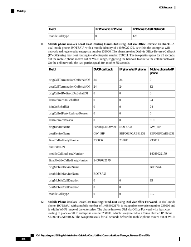
Page 347
range and the call is handed out to the cell network, following which the call continues for another 25
seconds.
Mobile Phone to IP Phone
IP Phone to IP Phone
Field
12
24
origCallTerminationOnBehalfOf
0
24
destCallTerminationOnBehalfOf
0
0
origCalledRedirectOnBehalfOf
24
0
lastRedirectOnBehalfOf
24
0
joinOnBehalfOf
0
0
origCalledPartyRedirectReason
319
0
lastRedirectReason
GW_SIP
BOTSAU
origDeviceName
SEP001FCAE91006
SEP001FCAE91006
destDeviceName
238011
238011
finalCalledPartyNumber
huntPilotDN
14089022179
mobileCallingPartyNumber
finalMobileCalledPartyNumber
BOTSAU
origMobileDeviceName
destMobileDeviceName
0
0
origMobileCallDuration
25
0
destMobileCallDuration
130
0
mobileCallType
13.
Send Call to Mobile - A Cisco Unified IP Phone SEP001FCAE90001 at 238011, makes a call to
enterprise number 238006. The called party answers the call on Cisco Unified IP Phone
SEP001FCAE90022. The conversation continues for 45 seconds before the called party presses the
Mobility softkey to send the call to the mobile phone, BOTSAU, at 12145551234. The call continues
on the mobile phone for another 35 seconds. The total call duration is 55 seconds.
IP Phone to Mobile
Phone
IP Phone to IP Phone
Announcement
Field
24
24
24
origCallTerminationOnBehalfOf
12
24
24
destCallTerminationOnBehalfOf
0
0
0
origCalledRedirectOnBehalfOf
Call Reporting and Billing Administration Guide for Cisco Unified Communications Manager, Release 15 and SUs
335
CDR Records
Mobility
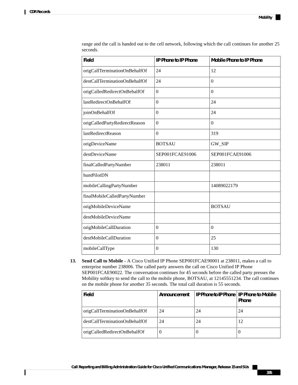
Page 348
IP Phone to Mobile
Phone
IP Phone to IP Phone
Announcement
Field
24
0
0
lastRedirectOnBehalfOf
24
0
0
joinOnBehalfOf
0
0
0
origCalledPartyRedirectReason
415
0
0
lastRedirectReason
SEP001FCAE90001
SEP001FCAE90001
SEP001FCAE90001
origDeviceName
GW_SIP
SEP001FCAE90022
GW_SIP
destDeviceName
238006
238006
238006
finalCalledPartyNumber
huntPilotDN
mobileCallingPartyNumber
12145551234
12145551234
finalMobileCalledPartyNumber
origMobileDeviceName
BOTSAU
BOTSAU
destMobileDeviceName
0
0
0
origMobileCallDuration
35
0
0
destMobileCallDuration
2048
0
0
mobileCallType
14.
Session Handoff - Cisco Unified IP Phone SEP001FCAE90001, at extension 1000, calls extension
2500. The phone rings at both a desk phone and a mobile phone. The called party answers on a mobile
phone, BOTSAU at mobile number 2145551234 and a conversation begins. After 35 seconds, the called
party triggers the Session Handoff feature and transfers the call to a desk phone. The call continues on
desk phone SEP001FCAE90022 for another 60 seconds.
IP Phone to IP Phone
IP Phone to Mobile
Phone
Parking Lot to Desk
Phone
Field
24
24
24
origCallTerminationOnBehalfOf
12
24
24
destCallTerminationOnBehalfOf
0
0
0
origCalledRedirectOnBehalfOf
24
0
0
lastRedirectOnBehalfOf
24
0
0
joinOnBehalfOf
0
0
0
origCalledPartyRedirectReason
403
0
0
lastRedirectReason
Call Reporting and Billing Administration Guide for Cisco Unified Communications Manager, Release 15 and SUs
336
CDR Records
Mobility
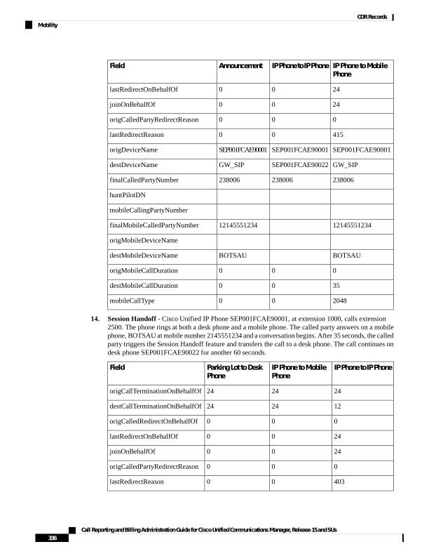
Page 349
IP Phone to IP Phone
IP Phone to Mobile
Phone
Parking Lot to Desk
Phone
Field
SEP001FCAE90001
SEP001FCAE90001
SEP001FCAE90001
origDeviceName
SEP001FCAE90022
BOTSARAH
SEP001FCAE90022
destDeviceName
2500
2500
2500
finalCalledPartyNumber
huntPilotDN
mobileCallingPartyNumber
2145551234
finalMobileCalledPartyNumber
origMobileDeviceName
BOTSARAH
destMobileDeviceName
0
0
0
origMobileCallDuration
10
15
0
destMobileCallDuration
5096
0
0
mobileCallType
Native Call Queuing
The Native Call Queuing feature provides an enhanced capability to handle incoming calls to a hunt pilot
number. Unified Communications Manager provides call queuing natively to users so that callers can be held
in a queue until hunt members are available to answer them. Callers in a queue receive an initial greeting
announcement followed by music on hold or tone on hold. If the caller remains in a queue for time, a secondary
announcement is played at a configured interval until the call can be answered—or until the maximum wait
timer expires.
Native Call Queuing Example
Unified Communications Manager cluster has four IP Phones: DN 1000, 1001, 1002, and 1003.
A hunt pilot (HP) 2000 is created with line group DN 1000 associated with it. So, this hunt pilot 2000 can
only handle one call. Now, Check the “Queuing” enabled flag on the hunt pilot 2000 configuration page. Set
the “Max Call Waiting Timer” to be 30 seconds, and select “Route the call to this destination” to be DN 1003.
Ideally, if a caller has been put into that queue for 30 seconds, then it will be routed to DN 1003.
1.
DN 1001 calls HP 2000, and 1000 answers the call.
2.
DN 1002 calls HP 2000. Since the agent is busy, call is queued.
3.
After 30 seconds, call is routed to DN 1003.
.
4.
DN 1003 answers the call.
Call Reporting and Billing Administration Guide for Cisco Unified Communications Manager, Release 15 and SUs
337
CDR Records
Native Call Queuing
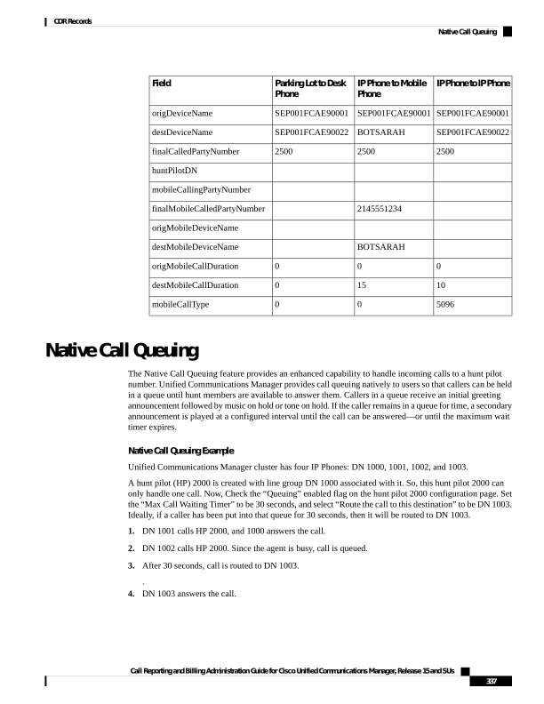
Page 350
CDR
Field Names
87029
globalCallID_callId
30117105
origLegCallIdentifier
1002
callingPartyNumber
2000
originalCalledPartyNumber
1
wasCallQueued
30
totalWaitTimeInQueue
Normal Calls (Cisco Unified IP Phone to Cisco Unified IP Phone)
Normal calls log three records per call; one CDR and two CMRs, one for each endpoint. In the CDR, the
“originalCalledPartyNumber” field contains the same Directory Number as the “finalCalledPartyNumber”
field.
Successful Normal Calls CDR Examples
A successful call between two Cisco Unified IP Phones generates a single CDR at the end of the call.
1.
The caller terminates a 60-second call. Because the calling party hangs up, the orig_CauseValue specifies
16 (Normal Clearing).
CDR
Field Names
1
globalCallID_callId
100
origLegCallIdentifier
101
destLegIdentifier
2001
callingPartyNumber
2309
originalCalledPartyNumber
2309
finalCalledPartyNumber
2309
lastRedirectDn
16
origCause_Value
0
dest_CauseValue
60
duration
2.
The called party clears a 60-second call. Because the called party hangs up, the dest_CauseValue specifies
16 (Normal Clearing).
Call Reporting and Billing Administration Guide for Cisco Unified Communications Manager, Release 15 and SUs
338
CDR Records
Normal Calls (Cisco Unified IP Phone to Cisco Unified IP Phone)
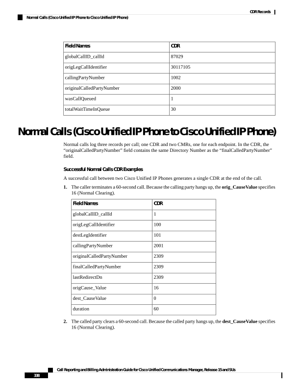
Page 351
CDR
Field Names
1
globalCallID_callId
100
origLegCallIdentifier
101
destLegIdentifier
2001
callingPartyNumber
2309
originalCalledPartyNumber
2309
finalCalledPartyNumber
2309
lastRedirectDn
0
origCause_Value
16
dest_CauseValue
60
duration
Original Calling Party on Transfer
This feature changes the calling party number for a consultation call of a Cisco Unity or Cisco Unity
Connection-initiated call transfer. The CDR of the consultation call shows that the original caller calls the
transfer destination, not that the Cisco Unity or Cisco Unity Connection port calls the transfer destination.
You must configure this feature in the service parameters in Unified Communications Manager. See additional
information at “Configuring CDR Service Parameters” section of the CDR Analysis and Reporting
Administration Guide.
Original Calling Party on Transfer CDR Example
4001 calls 4002. 4002 transfers the call to 4003. The system generates three CDRs:
• The call between the original parties (4001 to 4002).
• The consultation call between the transferring party (4002) to the final transfer destination (4003).
• The call from the transferred party (4001) to the transfer destination (4003).
originalCalledPartyNumber
CallingPartyNumber
Call
4002
4001
1
4003
4002
2
4003
4001
3
Call Reporting and Billing Administration Guide for Cisco Unified Communications Manager, Release 15 and SUs
339
CDR Records
Original Calling Party on Transfer
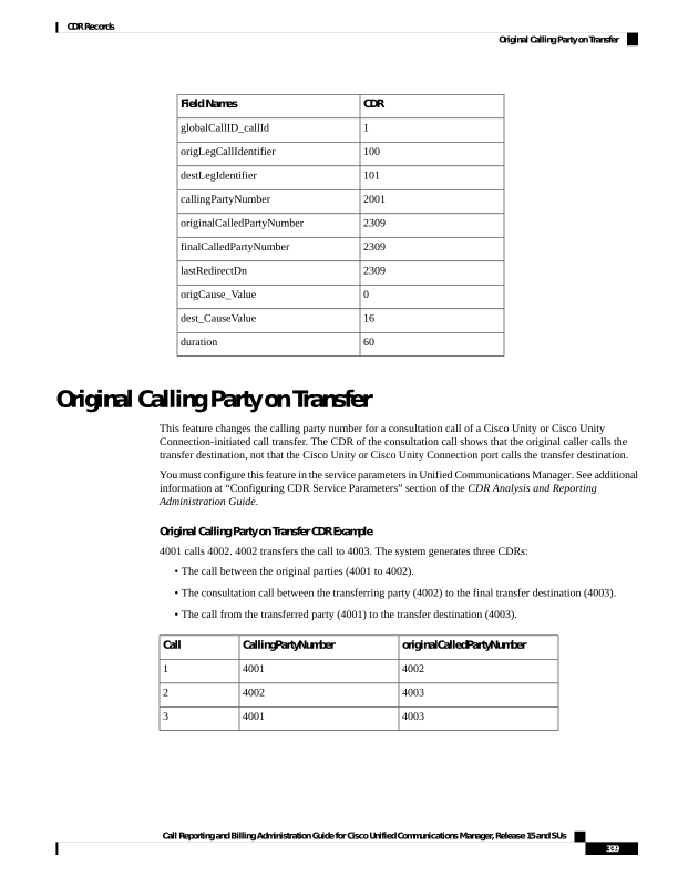
Page 352
No originalCallingParty field exists in the CDR.
Note
Personal Assistant Calls
This section contains information about Personal Assistant Calls.
Personal Assistant Direct Call
A personal assistant direct call acts similar to the Blind Transfer from the Calling Party call type.
Personal Assistant Direct Call CDR Example
The following table contains an example CDR for this scenario:
• User A (2101) calls a Personal Assistant route point (2000) and says “call User B.”
• The call transfers to User B (2105). In this case, User B did not configure any rules.
In the following example, 2000 represents the main personal assistant route point to reach personal assistant,
21XX represents the personal assistant interceptor route point, and 2001-2004 represents the media port.
Note
In all cases, 2101 specifies the calling number.
Duration
(secs)
Last Redirect
DN Partition
Last
Redir
DN
Original Called
Party Number
Partition
Original
Called
Party
Num
Final Called
Party Number
Partition
Final
Called
Party
Num
DestLeg
Identifier
Calling Party
Number
Partition
OrigLegCall
Identifier
Calling
Party
Num
34
Phones
2000
1023970182
2000
Phones
2004
16777219
PAManaged
16777217
2101
0
PAManaged
2105
1023970182
2105
PAManaged
2105
16777222
Phones
16777221
2004
5
PAManaged
2105
1023970191
2105
PAManaged
2105
16777222
PAManaged
16777217
2101
Personal Assistant Interceptor Going to Media Port and Transferring Call
This scenario acts similar to Blind Transfer from the Calling Party and Forwarded Calls actions.
Personal Assistant Interceptor Going to Media Port and Transferring the Call CDR Example
The following table contains an example CDR for this scenario:
• User A (2101) dials 2105.
• The personal assistant interceptor (21XX) picks up the call and redirects it to a media port (2002).
Call Reporting and Billing Administration Guide for Cisco Unified Communications Manager, Release 15 and SUs
340
CDR Records
Personal Assistant Calls

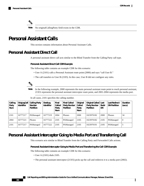
Page 353
• Personal assistant processes the call according to the rules (if any) and transfers the call to the destination
(2105), which has not configured any rules.
Duration
(secs)
Last Redirect
DN Partition
Last
Redir
DN
OriginalCalled
Party Number
Partition
Original
Called
Party
Num
Final Called
Party Number
Partition
Final
Called
Party
Num
DestLeg
Identifier
Calling Party
Number
Partition
OrigLegCall
Identifier
Calling
Party
Num
2
PAManaged
2105
1023970478
2105
PAManaged
2105
16777285
Phones
16777234
2002
9
" "
21xx
1023970478
2105
PA
2002
16777232
PAManaged
16777230
2101
5
" "
" "
1023970483
" "
" "
2101
16777230
PAManaged
16777235
2105
Personal Assistant Interceptor Going Directly to Destination
This scenario can have two different cases: with rules and with no rules.
Example Personal Assistant Interceptor Going Directly to Destination with No Rules CDR
The following table contains an example CDR for this scenario:
• User A (2101) dials 2105.
• The personal assistant interceptor (21XX) picks up the call, processes it according to the rules (if any),
and redirects the call to the destination (2105).
The following table contains an example CDR for this scenario:
Duration(secs)
Last
Redirect
DN
Partition
Last
Redirect
DN
Original
Called Party
Number
Partition
Original
Called
Party
Number
FinalCalled
Party
Number
Partition
Final
Called
Party
Number
DestLeg
Identifier
Calling Party
Number
Partition
OrigLegCall
Identifier
Calling
Party
Number
8
" "
21XX
1023970710
2105
PA
2105
16777242
PAManaged
16777240
2101
Example Personal Assistant Going Directly to Destination with Rule to Forward Calls to Different
Destination CDR
The following table contains an example CDR for this scenario:
• User A (2101) dials 2105.
• The Personal Assistant interceptor (21XX) picks up the call and processes it according to the rules.
• The Personal Assistant interceptor then redirects the call to the final destination (2110). In this case, 2105
configured a rule to forward the call to extension 2110.
Call Reporting and Billing Administration Guide for Cisco Unified Communications Manager, Release 15 and SUs
341
CDR Records
Personal Assistant Interceptor Going Directly to Destination
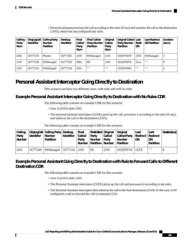
Page 354
Duration(secs)
Last
Redirect
DN
Partition
Last
Redirect
DN
Original
Called Party
Number
Partition
Original
Called
Party
Number
FinalCalled
Party
Number
Partition
Final
Called
Party
Number
DestLeg
Identifier
Calling Party
Number
Partition
OrigLegCall
Identifier
Calling
Party
Number
8
" "
21XX
1023970710
2105
PA
2110
16777242
PAManaged
16777240
2101
Personal Assistant Interceptor Going to Multiple Destinations
This scenario can have several different cases. In each case, User B (2105) configures a rule to reach him at
extension 2110 or 2120. This rule can activate when a caller calls Personal Assistant route point (2000) and
says “call User B” (direct case) or when the caller dials User B (2105) directly (interceptor case).
Personal Assistant Interceptor Going to Multiple Destinations CDR Examples
The following sections contain examples of each case. The following tables contain example CDRs for each
of these scenarios:
• Personal assistant direct multiple destinations: 2110 and 2120 (call accepted at first destination)
• Personal assistant direct multiple destinations: 2110 and 2120 (call accepted at second destination)
• Personal assistant direct multiple destinations: 2110 and 2120 (call accepted at third destination)
• Personal assistant intercept multiple destinations: 2110 and 2120 (call accepted at first destination)
• Personal assistant intercept multiple destinations: 2110 and 2120 (call accepted at second destination)
• Personal assistant intercept multiple destinations: 2110 and 2120 (call accepted at third destination)
Personal Assistant Direct Multiple Destinations: 2110 and 2120 (Call Accepted at First Destination)
• User A calls personal assistant and says, “call User B.”
• User B answers the call at 2110 extension.
Duration
(secs)
Last Redirect
DN Partition
Last
Redir
DN
Original Called
Party Number
Partition
Original
Called
PartyNum
Final Called
Party Number
Partition
Final
Called
Party
Num
DestLeg
Identifier
Calling Party
Number
Partition
OrigLegCall
Identifier
Calling
Party
Num
6
PAManaged
2110
1023971303
2110
PAManaged
2110
16777263
Phones
16777262
2004
22
Phones
2000
1023971303
2000
Phones
2004
16777260
PAManaged
16777258
2101
9
" "
" "
1023971312
" "
" "
2101
16777258
PAManaged
16777263
2110
Personal Assistant Direct Multiple Destinations: 2110 and 2120 (Call Accepted at Second Destination)
• User A calls personal assistant and says, “call User B.”
• User B answers the call at 2120 extension.
Call Reporting and Billing Administration Guide for Cisco Unified Communications Manager, Release 15 and SUs
342
CDR Records
Personal Assistant Interceptor Going to Multiple Destinations
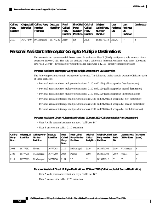
Page 355
Duration
(secs)
Last Redirect
DN Partition
Last
Redir
DN
Original Called
Party Number
Partition
Original
Called
Party
Num
Final Called
Party Number
Partition
Final
Called
Party
Num
DestLeg
Identifier
Calling Party
Number
Partition
OrigLegCall
Identifier
Calling
Party
Num
0
PAManaged
2110
1023971456
2110
PAManaged
2110
16777270
Phones
16777269
2001
4
PAManaged
2120
1023971467
2120
PAManaged
2120
16777273
Phones
16777272
2001
37
Phones
2000
1023971467
2000
Phones
2001
16777267
PAManaged
16777265
2101
7
" "
" "
1023971474
" "
" "
2101
16777265
PAManaged
16777273
2120
0
" "
" "
1023971476
" "
" "
" "
0
PAManaged
16777275
2110
Personal Assistant Direct Multiple Destinations: 2110 and 2120 (Call Accepted at Third Destination)
• User A calls personal assistant and says, “call User B.”
• User B does not answer at either extension 2110 or 2120.
• Personal Assistant transfers the call to the original destination (2105), and User B then answers at that
extension.
2105 (the original destination) represents the third destination in this case.
Note
Duration
(secs)
Last Redirect
DN Partition
Last
Redir
DN
Original Called
Party Number
Partition
Original
Called
Party
Num
Final Called
Party Number
Partition
Final
Called
Party
Num
DestLeg
Identifier
Calling Party
Number
Partition
OrigLegCall
Identifier
Calling
Party
Num
0
PAManaged
2110
1023971602
2110
PAManaged
2110
16777282
Phones
16777281
2002
0
PAManaged
2120
1023971615
2120
PAManaged
2120
16777285
Phones
16777284
2002
38
Phones
2000
1023971619
2000
Phones
2002
16777279
PAManaged
16777277
2101
0
PAManaged
2105
1023971619
2105
PAManaged
2105
16777288
Phones
16777287
2002
7
PAManaged
2105
1023971627
2105
PAManaged
2105
16777288
PAManaged
16777277
2101
0
" "
" "
1023971629
" "
" "
" "
0
PAManaged
16777289
2105
Personal Assistant Intercept Multiple Destinations: 2110 and 2120 (Call Accepted at First Destination)
• User A calls personal assistant and says, “call User B.”
• User B answers the call at extension 2110.
Call Reporting and Billing Administration Guide for Cisco Unified Communications Manager, Release 15 and SUs
343
CDR Records
Personal Assistant Interceptor Going to Multiple Destinations

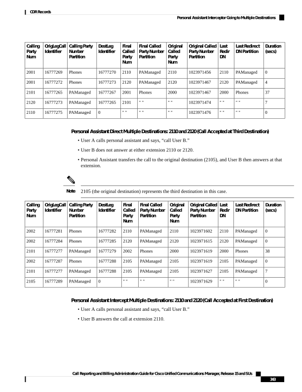
Page 356
Duration
(secs)
Last Redirect
DN Partition
Last
Redir
DN
OriginalCalled
Party Number
Partition
Original
Called
Party
Num
Final Called
Party Number
Partition
Final
Called
Party
Num
DestLeg
Identifier
Calling Party
Number
Partition
OrigLegCall
Identifier
Calling
Party
Num
4
PAManaged
2110
1023971740
2110
PAManaged
2110
16777296
Phones
16777295
2003
10
" "
21XX
1023971740
2105
PA
2003
16777293
PAManaged
16777291
2101
9
" "
" "
1023971749
" "
" "
2101
16777291
PAManaged
16777296
2110
Personal Assistant Intercept Multiple Destinations: 2110 and 2120 (Call Accepted at Second Destination)
• User A calls personal assistant and says, “call User B.”
• User B answers the call at extension 2120.
Duration
(secs)
Last Redirect
DN Partition
Last
Redir
DN
Original Called
Party Number
Partition
Original
Called
Party
Num
Final Called
Party Number
Partition
Final
Called
Party
Num
DestLeg
Identifier
Calling Party
Number
Partition
OrigLegCall
Identifier
Calling
Party
Num
0
PAManaged
2110
1023971815
2110
PAManaged
2110
16777303
Phones
16777302
2004
3
PAManaged
2120
1023971824
2120
PAManaged
2120
16777306
Phones
16777305
2004
22
" "
21XX
1023971824
2105
PA
2004
16777300
PAManaged
16777298
2101
8
" "
" "
1023971832
" "
" "
2101
16777298
PAManaged
16777306
2120
Personal Assistant Intercept Multiple Destinations: 2110 and 2120 (Call Accepted at Third Destination)
• User A calls personal assistant and says, “call User B.”
• User B does not answer at either extension 2110 or 2120.
• Personal assistant transfers the call to the original destination (2105), which User B then answers.
2110 (the original destination) represents the third destination in this case.
Note
Duration
(secs)
Last Redirect
DN Partition
Last
Redir
DN
OriginalCalled
Party Number
Partition
Original
Called
Party
Num
Final Called
Party Number
Partition
Final
Called
Party
Num
DestLeg
Identifier
Calling Party
Number
Partition
OrigLegCall
Identifier
Calling
Party
Num
0
PAManaged
2110
1023971923
2110
PAManaged
2110
16777313
Phones
16777312
2001
0
PAManaged
2120
1023971936
2120
PAManaged
2120
16777316
Phones
16777315
2001
30
" "
21XX
1023971940
2105
PA
2001
16777310
PAManaged
16777308
2101
0
PAManaged
2105
1023971940
2105
PAManaged
2105
16777319
Phones
16777318
2001
Call Reporting and Billing Administration Guide for Cisco Unified Communications Manager, Release 15 and SUs
344
CDR Records
Personal Assistant Interceptor Going to Multiple Destinations

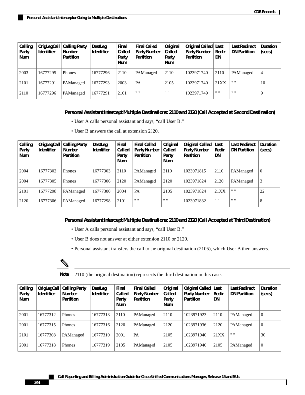
Page 357
Duration
(secs)
Last Redirect
DN Partition
Last
Redir
DN
OriginalCalled
Party Number
Partition
Original
Called
Party
Num
Final Called
Party Number
Partition
Final
Called
Party
Num
DestLeg
Identifier
Calling Party
Number
Partition
OrigLegCall
Identifier
Calling
Party
Num
12
PAManaged
2105
1023971953
2105
PAManaged
2105
16777319
PAManaged
16777308
2101
Personal Assistant Conferencing
Personal assistant conferencing acts similar to the ad hoc conferences call type.
Personal Assistant Conferencing CDR Example
The following table contains an example CDR for this scenario:
• User A calls personal assistant route point (2000) and says, “conference User B (2105) and User C
(2110).”
• Personal assistant conferences User B and C into User A conference.
Final Called Party
Number Partition
Final Called Party
Num
DestLeg
Identifier
Calling Party
Number Partition
OrigLegCall
Identifier
Calling
Party Num
PAManaged
2105
16777346
Phones
16777345
2003
Phones
2003
16777342
PAManaged
16777340
2101
PAManaged
2002
16777351
Phones
16777350
2003
" "
2110
16777347
Phones
16777342
2003
" "
b00110201001
16777352
PAManaged
16777351
2110
" "
b00110201001
16777349
PAManaged
16777346
2105
" "
b00110201001
16777348
PAManaged
16777340
2101
This table continues with this additional information.
Duration
(seconds)
Last Redirect DN
Partition
Last Redirect DN
Original Called Party
Number Partition
Original CalledParty
Number
6
PAManaged
2105
1023972575
2105
62
Phones
2003
1023972576
2000
39
PAManaged
2110
1023972595
2110
25
" "
b00110201001
1023972601
b00110201001
14
" "
b00110201001
1023972609
b00110201001
34
" "
b00110201001
1023972610
b00110201001
Call Reporting and Billing Administration Guide for Cisco Unified Communications Manager, Release 15 and SUs
345
CDR Records
Personal Assistant Conferencing

Page 358
Duration
(seconds)
Last Redirect DN
Partition
Last Redirect DN
Original Called Party
Number Partition
Original CalledParty
Number
34
" "
b00110201001
1023972610
b00110201001
Precedence Calls (MLPP)
Precedence calls take place the same as other calls except the precedence level fields get set in the CDR. Also,
when a higher level precedence call preempts a call, the cause codes indicate the reason for the preemption.
Precedence Call CDR Examples
1.
A call to another IP phone occurs by dialing a precedence pattern (precedence level 2).
Precedence Call CDR
Field Names
100
globalCallID_callId
12345
origLegCallIdentifier
12346
destLegIdentifier
2001
callingPartyNumber
826001
origCalledPartyNumber
0
origCause_Value
16
dest_CauseValue
2
origPrecedenceLevel
2
destPrecedenceLevel
2.
A precedence call gets received from another network (precedence level 1).
Precedence Call CDR
Field Names
102
globalCallID_callId
11111
origLegCallIdentifier
11112
destLegIdentifier
9728552001
callingPartyNumber
6001
origCalledPartyNumber
16
origCause_Value
0
dest_CauseValue
1
origPrecedenceLevel
Call Reporting and Billing Administration Guide for Cisco Unified Communications Manager, Release 15 and SUs
346
CDR Records
Precedence Calls (MLPP)
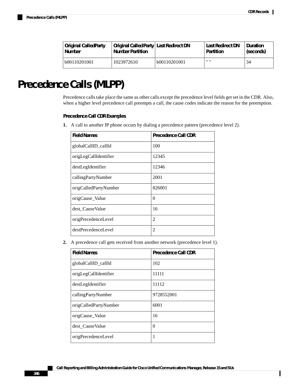
Page 359
Precedence Call CDR
Field Names
1
destPrecedenceLevel
3.
A call gets preempted by a higher precedence level call.
Higher Level Call CDR
Original call CDR
Field Names
10001
10000
globalCallID_callId
12345680
12345678
origLegCallIdentifier
12345681
12345679
destLegIdentifier
9728551234
2001
callingPartyNumber
826001
826001
origCalledPartyNumber
0
0
origCause_Value
16
9
dest_CauseValue
1
2
origPrecedenceLevel
1
2
destPrecedenceLevel
Redirection (3xx) Calls
This example shows CDRs for the redirection feature (3xx).
When a call is redirected by the Redirection Feature (3xx), the origCalledPartyRedirectOnBehalfOf and
lastRedirectRedirectOnBehalfOf fields specify UnifiedCM Redirection = 19. The
origCalledPartyRedirectReason and the lastRedirectRedirectReason fields specify Redirection = 162.
Redirection (3xx) CDR Example
Activate CFA on phone 10010 that is running SIP (registered to Unified Communications Manager) with a
CFA destination of 10000. 35010 calls 10010, which is CFA to 10000. The call gets redirected from 10010
to 10000. 10000 answers the call and talks for 1minute.
Original Call CDR
Field Names
11
globalCallID_callId
21832023
origLegCallIdentifier
21832026
destLegIdentifier
35010
callingPartyNumber
10010
originalCalledPartyNumber
10000
finalCalledPartyNumber
Call Reporting and Billing Administration Guide for Cisco Unified Communications Manager, Release 15 and SUs
347
CDR Records
Redirection (3xx) Calls
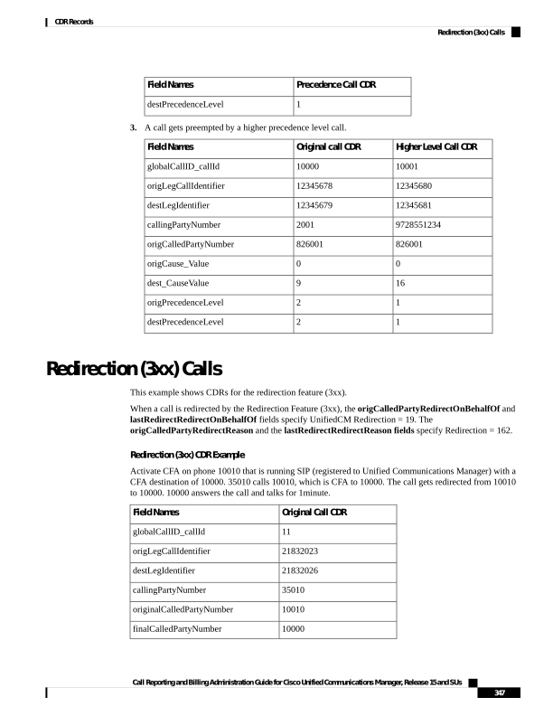
Page 360
Original Call CDR
Field Names
10010
lastRedirectDn
0
origCause_Value
16
dest_CauseValue
162
origCalledPartyRedirectReason
162
lastRedirectRedirectReason
19
origCalledPartyRedirectOnBehalfOf
19
lastRedirectRedirectOnBehalfOf
0
origTerminationOnBehalfOf
12
destTerminationOnBehalfOf
19
joinOnBehalfOf
60
duration
Redirecting Number Transformation
When the redirecting number transformation feature is enabled, original called and last redirecting number
are transformed before it sends out in outgoing setup message.
Redirecting Number Transformation Example
1.
CCM1 - Phone A [ 180000 ] , Phone B [ 180001 ] , Phone C [ 180002 ]
2.
SIP trunk is configured on CCM1 pointing to SIP Gateway
3.
Phone B has external mask set as +9111XXXX
4.
Phone C has external mask set as +9122XXXX
On SIP trunk, redirecting party CSS is configured which has the partitions P1 and there is a Calling Party
transformation pattern associated with P1. This pattern has external phone number mask enabled.
Scenario
A - calls Phone B ---- CFA - Phone C CFA --- SIP Trunk --- SIP Gateway
B - Original Called Party, C - Last Redirecting Party
There are 2 diversion headers corresponding to original and last redirecting party that is sent out in outgoing
SIP INVITE message and these diversion headers have transformed redirecting number, that is, +91110001
and +91220002.
These values are also stored in CDR records. Transformed original called number will be stored in
outpulsedOriginalCalledPartyNumber and transformed last redirecting number will be stored in
outpulsedLastRedirectingNumber.
Call Reporting and Billing Administration Guide for Cisco Unified Communications Manager, Release 15 and SUs
348
CDR Records
Redirecting Number Transformation
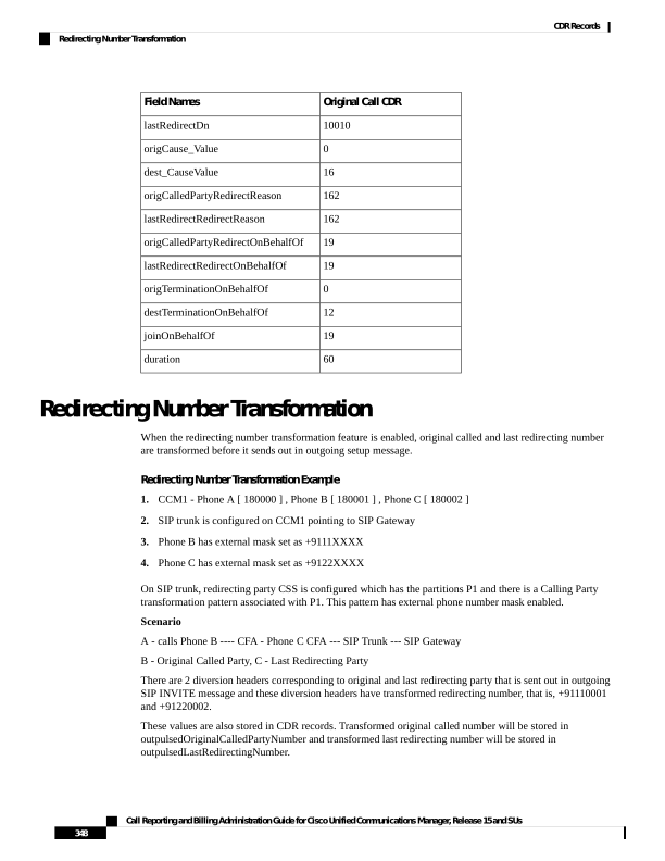
Page 361
CDR
Field Names
115010
globalCallID_callId
30751507
origLegCallIdentifier
180000
callingPartyNumber
880003
outpulsedCallingPartyNumber
+91110001
outpulsedOriginalCalledPartyNumber
+91220002
outpulsedLastRedirectingNumber
Refer Calls
See the replaces calls topic for an example of Refer with Replaces.
Replaces Calls
The examples show CDRs for various types of Replaces calls.
Replaces CDR Examples
1.
Invite with Replaces – Phone 35010 that is running SIP calls phone 35020 that is running SIP. The
transfer button gets pressed on 35010, and a call gets placed to SCCP phone 3000, 3000 answers the call;
then, phone 35010 completes the transfer. The final transferred call occurs between 35020 and 3000.
When the transfer is complete, the system sends an Invite with Replaces to Unified Communications Manager.
Note
Reverted Call CDR
Original Call CDR
Field Names
5045248
5045247
globalCallID_callId
21822469
21822467
origLegCallIdentifier
21822468
21822468
destLegIdentifier
35020
35010
callingPartyNumber
3000
3000
originalCalledPartyNumber
3000
3000
finalCalledPartyNumber
35010
3000
lastRedirectDn
0
393216
origCause_Value
16
393216
dest_CauseValue
Call Reporting and Billing Administration Guide for Cisco Unified Communications Manager, Release 15 and SUs
349
CDR Records
Refer Calls

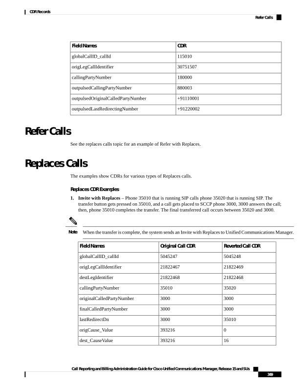
Page 362
Reverted Call CDR
Original Call CDR
Field Names
0
0
origCalledPartyRedirectReason
146
0
lastRedirectRedirectReason
0
0
origCalledPartyRedirectOnBehalfOf
18
0
lastRedirectRedirectOnBehalfOf
0
18
origTerminationOnBehalfOf
12
18
destTerminationOnBehalfOf
18
0
joinOnBehalfOf
60
5
duration
2.
Refer with Replaces – Phone 35010 that is running SIP calls SCCP 3000, the transfer button gets pressed
on 35010, and a call is placed to SCCP 3001; 3001 answers the call; then, phone 35010 completes the
transfer. The final transferred call occurs between 3000 and 3001.
When the transfer completes, a Refer with Replaces gets sent to Unified Communications Manager.
Note
Final Transferred Call
CDR
Consultation Call CDR
Original Call CDR
Field Names
5045245
5045246
5045245
globalCallID_callId
21822462
21822463
21822461
origLegCallIdentifier
21822464
21822464
21822462
destLegIdentifier
3000
35010
35010
callingPartyNumber
3001
3001
3000
originalCalledPartyNumber
3001
3001
3000
finalCalledPartyNumber
35010
3001
3000
lastRedirectDn
16
393216
393216
origCause_Value
0
393216
393216
dest_CauseValue
130
0
0
origCalledPartyRedirectReason
146
0
0
lastRedirectRedirectReason
17
0
0
origCalledPartyRedirectOnBehalfOf
18
0
0
lastRedirectRedirectOnBehalfOf
Call Reporting and Billing Administration Guide for Cisco Unified Communications Manager, Release 15 and SUs
350
CDR Records
Replaces Calls


Page 363
Final Transferred Call
CDR
Consultation Call CDR
Original Call CDR
Field Names
12
18
17
origTerminationOnBehalfOf
17
18
17
destTerminationOnBehalfOf
18
0
0
joinOnBehalfOf
25
4
25
duration
RSVP
These fields identify the status of RSVP reservation for the call. Be aware that the Unified Communications
Manager RSVP CDR status field value gets concatenated, and the system retains the last 32 status values for
the call.
For example, if a call is established with “Optional” policy, and the initial RSVP reservation is successful,
and then it subsequently loses its bandwidth reservation and then regains its bandwidth reservation after retry,
for several times during middle of the call, the call ends with a successful RSVP reservation. The CDR shows
the following string as the UnifiedCommunication RSVP reservation status for that particular stream:
“2:5:2:5:2:5:2” (success:lost_bw:success:lost_bw:success:lost_bw:success).
RSVP Call CDR Examples
1.
The example represents a call that gets established with “Optional” policy, and the initial RSVP reservation
succeeds. The parties talk for 5minutes.
CDR
Field Names
300
globalCallID_callId
16777300
origLegCallIdentifier
16777301
destLegIdentifier
20000
callingPartyNumber
20001
origCalledPartyNumber
20001
finalCalledPartyNumber
20001
lastRedirectDn
0
origCause_Value
16
dest_CauseValue
2
origDTMFMethod
2
destDTMFMethod
300
duration
Call Reporting and Billing Administration Guide for Cisco Unified Communications Manager, Release 15 and SUs
351
CDR Records
RSVP
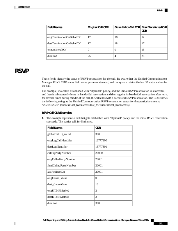
Page 364
The example represents a call that is established with “Optional” policy, and the initial RSVP reservation
succeeds, then it loses its bandwidth reservation but regains it after a retry. The parties talk for 1minute.
CDR
Field Names
301
globalCallID_callId
16777302
origLegCallIdentifier
16777303
destLegIdentifier
20000
callingPartyNumber
20001
origCalledPartyNumber
20001
finalCalledPartyNumber
20001
lastRedirectDn
0
origCause_Value
16
dest_CauseValue
2:5:2
origDTMFMethod
2:5:2
destDTMFMethod
60
duration
Secure Conference Meet-Me
The following example shows a CDR for a meet-me secure conference. 35010 calls into a secure meet-me
conference, but 35010 is a non-secure phone. Because 35010 does not meet the minimum security level of
the meet-me conference, the call gets cleared with the cause code of 58 (meet-me conference minimum security
level not met).
Secure Conference Meet-Me CDR Example
Call to the Meet-Me Conference CDR
Field Names
5045247
globalCallID_callId
123456879
origLegCallIdentifier
123456999
destLegIdentifier
35010
callingPartyNumber
50000
originalCalledPartyNumber
50000
finalCalledPartyNumber
50000
lastRedirectDn
Call Reporting and Billing Administration Guide for Cisco Unified Communications Manager, Release 15 and SUs
352
CDR Records
Secure Conference Meet-Me
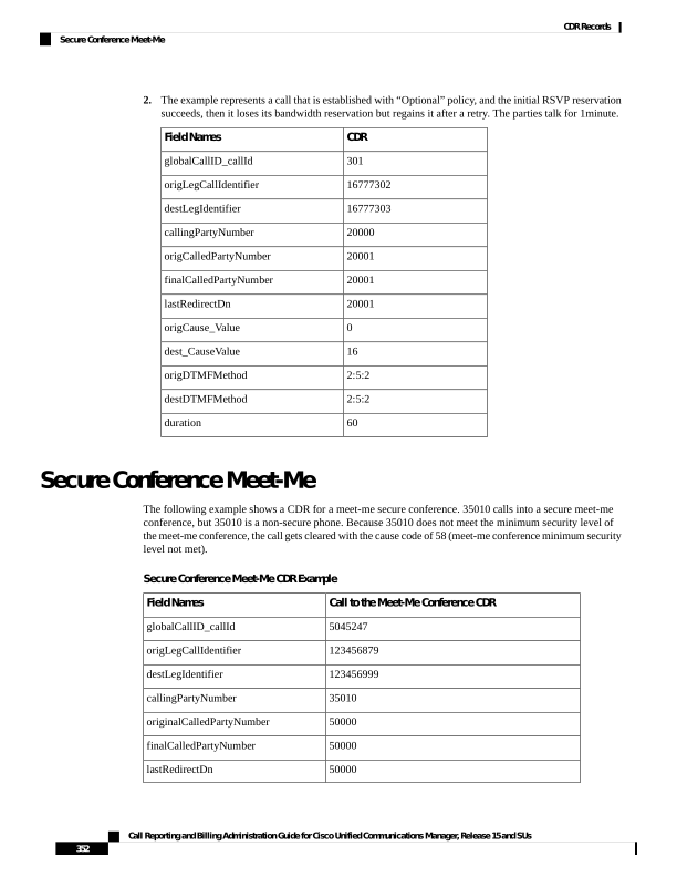
Page 365
Call to the Meet-Me Conference CDR
Field Names
58
origCause_Value
0
dest_CauseValue
0
origCalledPartyRedirectReason
0
lastRedirectRedirectReason
0
origCalledPartyRedirectOnBehalfOf
0
lastRedirectRedirectOnBehalfOf
6
origTerminationOnBehalfOf
6
destTerminationOnBehalfOf
Short Calls
A short call, with a CdrLogCallsWithZeroDurationFlag set at True and a duration of less than 1second,
appears as a zero duration call in the CDR. The DateTimeConnect field, which shows the actual connect
time of the call, differentiates these calls from failed calls. For failed calls (which never connected), this value
equals zero.
Short Calls CDR Example
The following table contains an example of a successful On Net call with a duration of less than 1second that
the called party cleared.
Duration
DateTime
Connect
Dest
Cause
Orig
Cause
Original
CalledPartition
Original
CalledParty
Calling
Partition
Calling
Party
0
973795815
16
0
Marketing
2309
Accounts
2001
SIP Call with URL in CallingPartyNumber Field
Calling and called parties can have SIP calls where the extension number is a URL. The extension number
can use all printable ASCII characters. Do not leave any spaces in the URL. For example, extension “1000
1001” does not get accepted as a valid URL.
Printable ASCII characters represent characters with ASCII code (in decimal) from 33 to 126.
Note
SIP Call with URL in CallingPartyNumber Field CDR Example
The SIP trunk of the Unified Communications Manager receives an incoming call. The call contains a SIP
URL for the callingPartyNumber.
Call Reporting and Billing Administration Guide for Cisco Unified Communications Manager, Release 15 and SUs
353
CDR Records
Short Calls

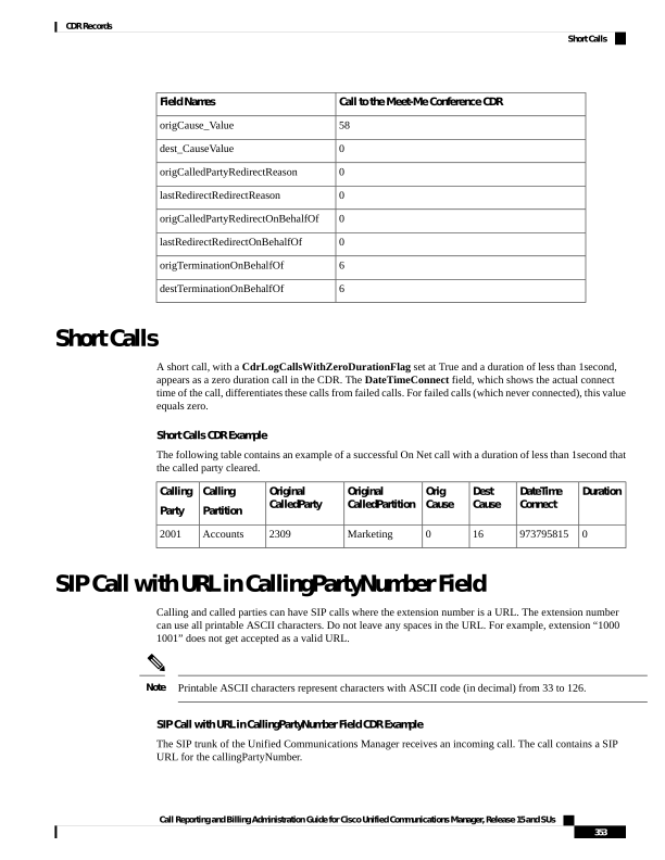
Page 366
Values
Field Names
1
globalCallID_callId
100
origLegCallIdentifier
101
destLegIdentifier
bob@abc.com
callingPartyNumber
2309
originalCalledPartyNumber
2309
finalCalledPartyNumber
2309
lastRedirectDn
16
origCause_Value
0
dest_CauseValue
60
duration
Successful on Net Calls
A successful call between two Cisco Unified IP Phones generates a single CDR at the end of the call.
Successful On Net Call CDR Examples
The following table contains two examples:
• A—A 60-second call that the caller terminates
• B—A 60-second call that the called party clears
Duration
Dest
Cause
Orig
Cause
Original Called
Partition
Original Called
Party
Calling
Partition
Calling
Party
60
0
16
Marketing
2309
Accounts
2001
A
60
16
0
Marketing
2309
Accounts
2001
B
Transferred Calls
Calls that are transferred generate multiple CDRs. One CDR exists for the original call, one for the consultation
call, and another for the final transferred call.
For the original call, the origCause_value and destCause_value gets set to split = 393216, which indicates
the call was split. The origCallTerminationOnBehalfOf and destCallTerminationOnBehalfOf fields get
set to Transfer = 10 to indicate that this call was involved in a transfer.
Call Reporting and Billing Administration Guide for Cisco Unified Communications Manager, Release 15 and SUs
354
CDR Records
Successful on Net Calls
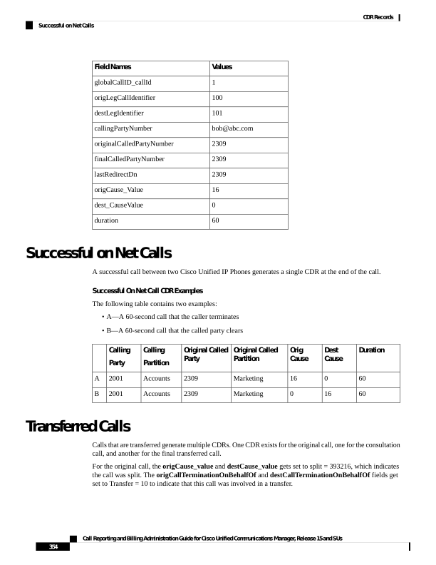
Page 367
For the consultation call, the origCause_value and destCause_value fields get set to split = 393216, which
indicates that the call was split. The origCallTerminationOnBehalfOf and destCallTerminationOnBehalfOf
fields get set to Transfer = 10 to indicate that this call was involved in a transfer.
For the final transferred call, the joinOnBehalfOf field gets set to Transfer = 10 to indicate that this call
resulted from a transfer.
Transferred Calls CDR Examples
The following examples, which are not an exhaustive set, illustrate the records that would be generated under
the stated circumstances. These examples help clarify what records are generated on transferred calls.
Blind Transfer From the Calling Party CDR Example
Call goes from extension 2001 to a PSTN number; they talk for 120 seconds. 2001 initiates a blind transfer
to 2002. CDR 1 (original call) shows a call from extension 2001 to a PSTN number, talking for 120 seconds.
CDR 2 (consultation call) shows a call from 2001 to extension 2002. CDR 3 represents the final transferred
call where 2001 completes the transfer, drops out of the call, and leaves a call between the PSTN and 2002.
Final Transferred CD
Consultation Call CDR
Original Call CDR
Field Names
1
2
1
globalCallID_callId
102
103
101
origLegCallIdentifier
104
104
102
destLegIdentifier
3071111
2001
2001
callingPartyNumber
2002
2002
3071111
originalCalledPartyNumber
2002
2002
3071111
finalCalledPartyNumber
2001
2002
3071111
lastRedirectDn
16
393216
393216
origCause_Value
0
393216
393216
dest_CauseValue
0
10
10
origTerminationOnBehalfOf
0
10
10
destTerminationOnBehalfOf
10
0
0
joinOnBehalfOf
360
0
120
duration
Consultation Transfer From the Calling Party CDR Example
Call goes from extension 2001 to a PSTN number; they talk for 60 seconds. 2001 initiates a consultation
transfer to 2002 and talks for 10 seconds before the transfer completes. The final transferred call talks for 360
seconds. CDR 1 (original call) shows a call from extension 2001 to a PSTN number, talking for 60 seconds.
CDR 2 (consultation call) shows a call from 2001 to extension 2002, talking for 10 seconds. CDR 3 represents
the final transferred call where 2001 completes the transfer, drops out of the call, and leaves a call between
the PSTN and 2002.
Call Reporting and Billing Administration Guide for Cisco Unified Communications Manager, Release 15 and SUs
355
CDR Records
Transferred Calls

Page 368
Final Transferred Call CD
Consultation Call CDR
Original Call CDR
Field Names
1
2
1
globalCallID_callId
112
113
111
origLegCallIdentifier
114
114
112
destLegIdentifier
3071111
2001
2001
callingPartyNumber
2002
2002
3071111
originalCalledPartyNumber
2002
2002
3071111
finalCalledPartyNumber
2001
50001
50001
lastRedirectDn
16
393216
393216
origCause_Value
0
393216
393216
dest_CauseValue
0
10
10
origTerminationOnBehalfOf
0
10
10
destTerminationOnBehalfOf
10
0
0
joinOnBehalfOf
360
10
60
duration
Blind Transfer From the Called Party CDR Example
Call goes from 50000 to 50001; they talk for 120 seconds. 50001 initiates a blind transfer to 50002. CDR 1
(original call) shows a call from extension 50001 to 50002, talking for 120 seconds. CDR 2 (consultation
call) shows a call from 50001 to extension 50002. CDR 3 represents the final transferred call where 50001
completes the transfer, drops out of the call, and leaves a call between 50000 and 50002.
Final Transferred Call CD
Consultation Call CDR
Original Call CDR
Field Names
1
2
1
globalCallID_callId
200
202
200
origLegCallIdentifier
203
203
201
destLegIdentifier
50000
50001
50000
callingPartyNumber
50002
50002
50001
originalCalledPartyNumber
50002
50002
50001
finalCalledPartyNumber
50001
50001
50001
lastRedirectDn
16
393216
393216
origCause_Value
0
393216
393216
dest_CauseValue
0
10
10
origTerminationOnBehalfOf
Call Reporting and Billing Administration Guide for Cisco Unified Communications Manager, Release 15 and SUs
356
CDR Records
Transferred Calls
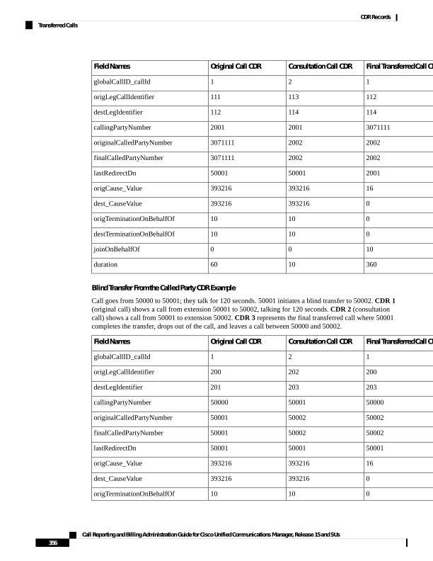
Page 369
Final Transferred Ca
Consultation Call CDR
Original Call CDR
Field Names
0
10
10
destTerminationOnBehalfOf
10
0
0
joinOnBehalfOf
360
0
120
duration
Consultation Transfer From the Called Party CDR Example
Call goes from 50000 to 50001; they talk for 120 seconds. 50000 initiates a blind transfer to 50002. CDR1
(original call) shows a call from extension 50000 to a 50001, talking for 120 seconds. CDR2 (consultation
call) shows a call from 50000 to extension 50002. CDR3 represents the final transferred call where 50000
completes the transfer, drops out of the call, and leaves a call between 50001 and 50002.
Final Transferred Ca
Consultation Call CDR
Original Call CDR
Field Names
1
2
1
globalCallID_callId
201
202
200
origLegCallIdentifier
203
203
201
destLegIdentifier
50000
50001
50000
callingPartyNumber
50002
50002
50001
originalCalledPartyNumber
50002
50002
50001
finalCalledPartyNumber
50001
50001
50001
lastRedirectDn
16
393216
393216
origCause_Value
0
393216
393216
dest_CauseValue
0
10
10
origTerminationOnBehalfOf
0
10
10
destTerminationOnBehalfOf
10
0
0
joinOnBehalfOf
360
0
120
duration
Video Calls
The following example shows a CDR for a video call.
Video Calls CDR Example
Calling party 51234 calls the called party 57890. In the following example, let 100 = H.261,
187962284=172.19.52.11, 288625580=172.19.52.17, 320=320K, and 2=QCIF.
Call Reporting and Billing Administration Guide for Cisco Unified Communications Manager, Release 15 and SUs
357
CDR Records
Video Calls
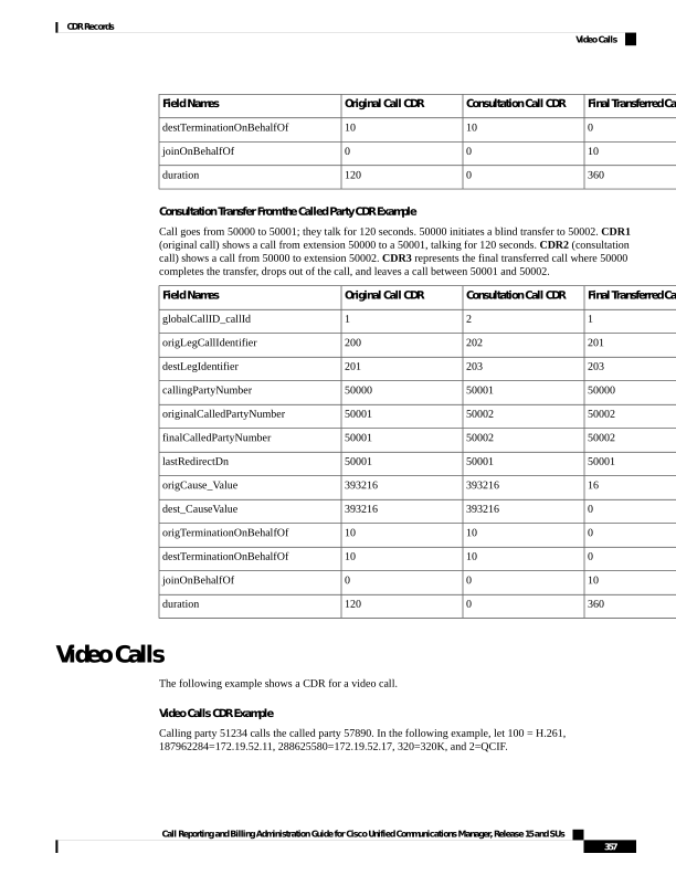
Page 370
Video Call CDR
Field Names
121
globalCallID_callId
101
origLegCallIdentifier
102
destLegIdentifier
51234
callingPartyNumber
57890
origCalledPartyNumber
57890
finalCalledPartyNumber
57890
lastRedirectDn
0
origCause_Value
16
dest_CauseValue
100
origVideoCap_Codec
320
origVideoCap_Bandwidth
2
origVideoCap_Resolution
187962284
origVideoTransportAddress_IP
49208
origVideoTransportAddress_Port
100
destVideoCap_Codec
320
destVideoCap_Bandwidth
2
destVideoCap_Resolution
288625580
destVideoTransportAddress_IP
49254
destVideoTransportAddress_Port
Video Conference Calls
Calls that are part of a video conference have multiple records logged. The number of CDR records that are
generated depends on the number of parties in the video conference. One CDR record exists for each party
in the video conference, one for the original placed call, one for each setup call that was used to join other
parties to the video conference, and one for the last two parties that are connected in the video conference.
Therefore, for a three party ad hoc video conference, six CDR records exist:
• 1 record for the original call
• 3 records for the parties that connected to the conference
• 1 record for each setup call
Call Reporting and Billing Administration Guide for Cisco Unified Communications Manager, Release 15 and SUs
358
CDR Records
Video Conference Calls
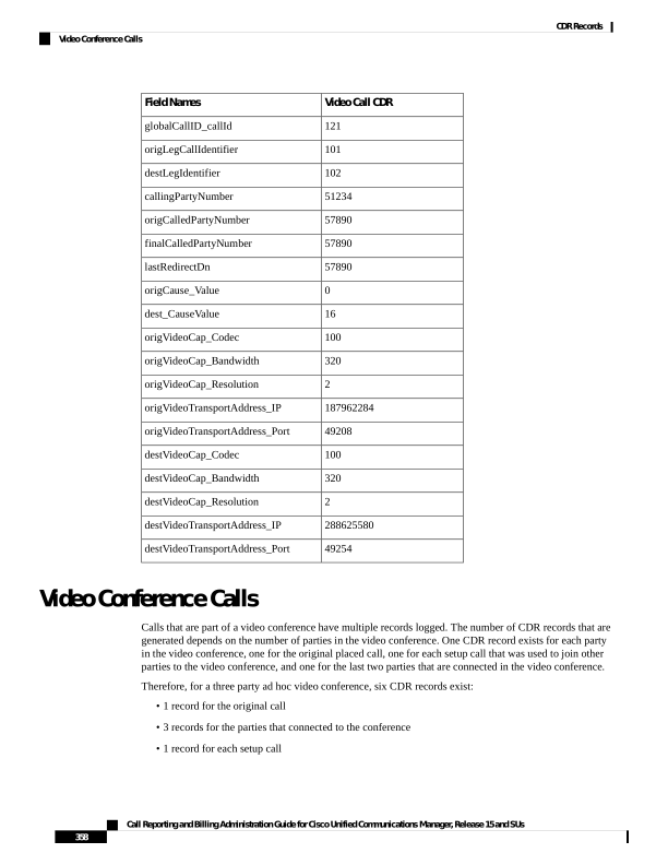
Page 371
• 1 record for the final two parties in the conference
You can associate the setup calls with the correct call leg in the conference by examining the calling leg ID
and called leg ID.
The conference bridge device has special significance to the Unified Communications Manager, and calls to
the conference bridge appear as calls to the conference bridge device. A special number in the form
"b0019901001" shows the conference bridge port.
All calls in or out of the conference bridge get shown going into the conference bridge, regardless of the actual
direction. By examining the setup call CDR records, you can determine the original direction of each call.
You can find the conference controller information in the comment field of the CDR. The format of this
information follows:
Comment field = "ConfControllerDn=1000;ConfControllerDeviceName=SEP0003"
• The conference controller DN + conference controller device name uniquely identifies the conference
controller. You need the device name in the case of shared lines.
• If the call is involved in multiple conference calls, the comment field will contain multiple conference
controller information. This could happen in case the conference goes down to two parties and one of
these parties starts another conference. If this is the case, the last conference controller information in
the comment field will identify the conference controller.
The call legs that are connected to the conference will have the following fields information:
• The finalCalledPartyNumber field contains the conference bridge number "b0019901001".
• The origCalledPtyRedirectOnBehalfOf field gets set to (Conference = 4).
• The lastRedirectRedirectOnBehalfOf field gets set to (Conference = 4).
• The joinOnBehalfOf field gets set to (Conference = 4).
• The comment field identifies the conference controller.
• The destConversationId field remains the same for all members in the conference. You can use
this field to identify members of a conference call.
The original placed call and all setup calls that were used to join parties to the conference will have the
following fields:
• The origCallTerminationOnBehalfOf field gets set to (Conference = 4).
• The destCallTerminationOnBehalfOf field gets set to (Conference = 4).
Video Conference Call CDR Example
1.
Call from 2001 to 2309; 2309 answers, and they talk for 60 seconds.
2.
2001 presses the conference softkey and dials 3071111.
3.
307111 answers and talks for 20 seconds; 2001 presses the conference softkey to complete the conference.
4.
The three members of the conference talk for 360 seconds.
5.
3071111 hangs up; 2001 and 2309 stay in the conference. Because only two participants remain in the
conference, the conference feature joins the two directly together, and they talk for another 55seconds.
Call Reporting and Billing Administration Guide for Cisco Unified Communications Manager, Release 15 and SUs
359
CDR Records
Video Conference Calls
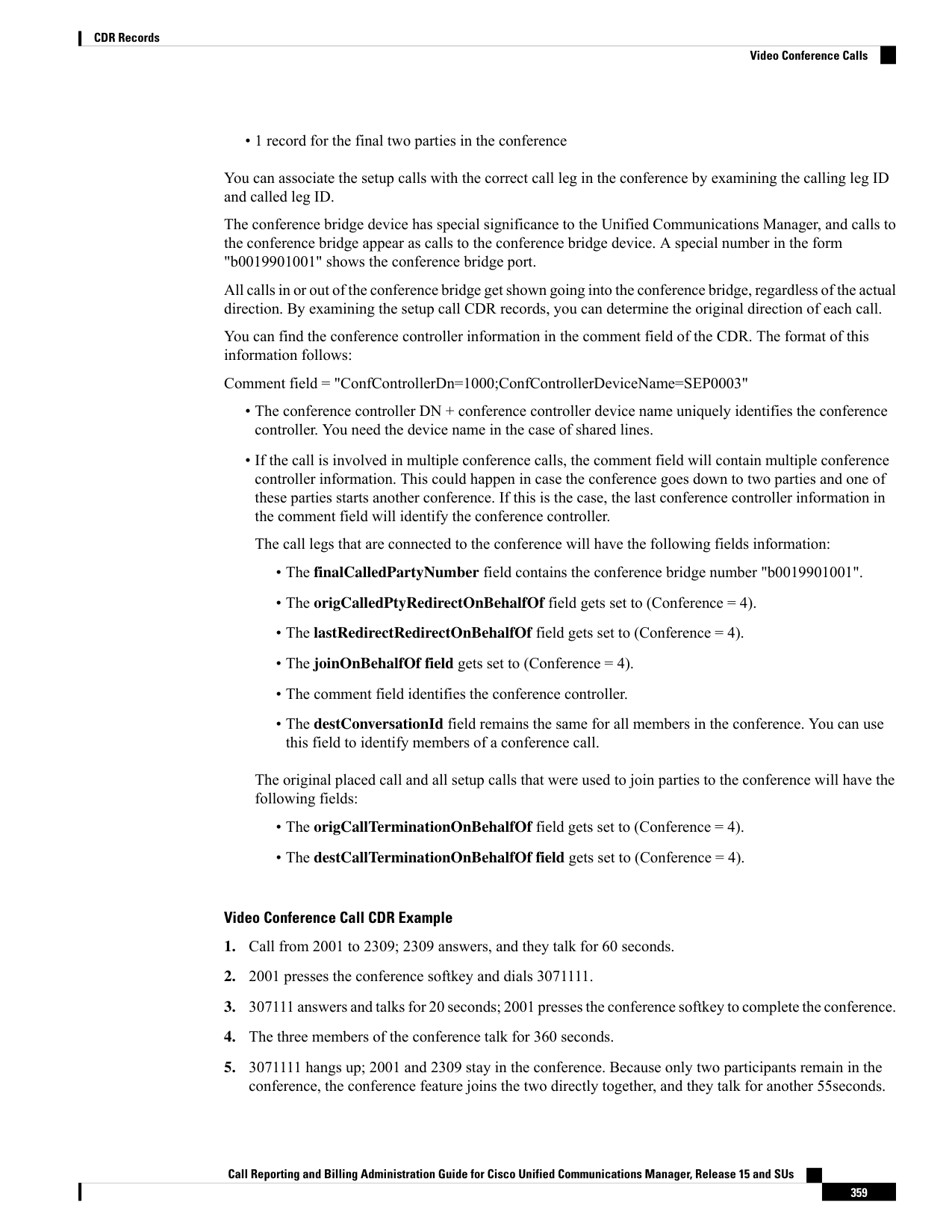
Page 372
Each video conference call leg gets shown placing a call into the conference bridge. The call gets shown as
a call into the bridge, regardless of the actual direction of the call.
Note
Final CDR
Conference CDR 3
Conference CDR 2
Conference CDR 1
Setup Call CDR
Orig Call CDR
FieldNames
1
1
1
2
1
globalCallID_callId
101
106
102
101
105
101
origLegCallIdentifier
102
117
116
115
106
102
destLegIdentifier
2001
3071111
2309
2001
2001
2001
callingPartyNumber
2309
b0029901001
b0029901001
b0029901001
3071111
2309
originalCalledPartyNumber
2309
b0029901001
b0029901001
b0029901001
3071111
2309
finalCalledPartyNumber
b0029901001
b0029901001
b0029901001
b0029901001
3071111
2001
lastRedirectDn
16
393216
393216
16
0
393216
origCause_Value
0
393216
393216
393216
0
393216
dest_CauseValue
103
103
103
103
103
103
origVideoCap_Codec
320
320
320
320
320
320
origVideoCap_Bandwidth
0
0
0
0
0
0
origVideoCap_Resolution
552953152
-945658560
-822647488
552953152
552953152
552953152
origVideoTransportAddress_IP
5445
5445
5445
5445
5445
5445
origVideoTransportAddress_Port
103
103
103
103
103
103
destVideoCap_Codec
320
320
320
320
320
320
destVideoCap_Bandwidth
0
0
0
0
0
0
destVideoCap_Resolution
-822647488
-666216182
-666216182
-666216182
-945658560
-822647488
destVideoTransportAddress_IP
5445
10001
10004
10000
10002
5445
destVideoTransportAddress_Port
0
0
0
0
0
0
origCalledPartyRedirectReason
98
0
0
0
0
0
lastRedirectRedirectReason
12
4
12
12
4
4
origTerminationOnBehalfOf
4
4
0
0
4
4
destTerminationOnBehalfOf
0
4
4
4
0
0
origCalledRedirectOnBehalfOf
4
4
4
4
0
0
lastRedirectRedirectOnBehalfOf
4
4
4
4
0
0
joinOnBehalfOf
0
1
1
1
0
Conversation ID
55
360
360
360
60
duration
Call Reporting and Billing Administration Guide for Cisco Unified Communications Manager, Release 15 and SUs
360
CDR Records
Video Conference Calls


Page 373
Comment
Orig Call CDR
ConfControllerDn=2001;ConfControlerDeviceName=SEP0003E333FEBD
Setup Call CDR
ConfControllerDn=2001;ConfControlerDeviceName=SEP0003E333FEBD
Conference CDR 1
ConfControllerDn=2001;ConfControlerDeviceName=SEP0003E333FEBD
Conference CDR 2
ConfControllerDn=2001;ConfControlerDeviceName=SEP0003E333FEBD
Conference CDR 3
Final CDR
Call Reporting and Billing Administration Guide for Cisco Unified Communications Manager, Release 15 and SUs
361
CDR Records
Video Conference Calls
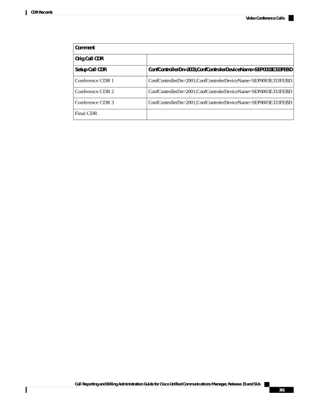
Page 374
Call Reporting and Billing Administration Guide for Cisco Unified Communications Manager, Release 15 and SUs
362
CDR Records
Video Conference Calls

Page 375
P A R T III
CMR Records
• Call Management Records, on page 365
• CMR Field Descriptions, on page 371
• CMR Examples, on page 383

Page 376
Page 377
C H A P T E R 11
Call Management Records
This chapter describes the format and logic of the call management records (CMRs) that the Unified
Communications Manager system generates, and how to access the CMR files.
• Call Management Records Overview, on page 365
• CMR Processing, on page 365
• CMRs for SIP Trunks, on page 366
• CMRs for Headsets, on page 368
• CMRs for Headsets, on page 369
• Set Up CMRs, on page 369
• CPU Utilization, on page 370
Call Management Records Overview
The Unified Communications Manager system generates call management records (CMRs). You can use this
information for post-processing activities such as generating billing records and network analysis.
When you install your system, CMRs remain disabled by default, you can enable or disable CMRs at any
time that the system is in operation. You do not need to restart Unified Communications Manager for the
change to take the effect. The system responds to all changes within a few seconds. The system enables CMR
or diagnostic data separately from CDR data.
CMR Processing
The CMR records store information about the quality of the streamed audio and video of the call.
When Unified Communications Manager places or receives a call, the system generates a CDR record when
the call terminates. The system writes the CDR to a flat file (text file). Inside the Unified Communications
Manager, the call control process generates CDR records. The system writes records when significant changes
occur to a given call, such as ending the call, transferring the call, redirecting the call, splitting the call, joining
a call, and so forth.
When CMR records are enabled, the number of records that are written varies by type of call and the call
scenario. When Diagnostics are enabled, the device generates CMR records for each call. The system writes
one CMR record for each IP phone that is involved in the call or for each Media Gateway Control Protocol
(MGCP) gateway. The system sends these records to EnvProcessCdr where they get written to flat files.
Call Reporting and Billing Administration Guide for Cisco Unified Communications Manager, Release 15 and SUs
365

Page 378
For Hold and Resume calls on SCCP devices, multiple CMR Records are generated based on the number of
times the call is put on hold.
Note
The Unified Communications Manager generates CMR records but does not perform any post processing on
the records. The system writes the records to comma-delimited flat files and periodically passes them to the
CDR Repository. The CMR files represent a specific filename format within the flat file.
Filename Format
The following example shows the full format of the filename:
tag_clusterId_nodeId_datetime_seqNumber
• tag—Identifies the type of file, either CDR or CMR.
• clusterId—Identifies the cluster or server where the Unified Communications Manager database exists.
• nodeId—Identifies the node.
• datetime—Specifies UTC time in yyyymmddhhmm format.
• seqnumber—Specifies sequence number.
An example of the filename follows:
• cmr_Cluster1_02_200404061011_6125
Flat File Format
The CMR flat files have the following format:
• Line 1—List of field names in comma separated format.
• Line 2—List of field types in comma separated format.
• Line 3—Data in comma separated format.
• Line 4—Data in comma separated format.
The following example shows a flat file:
Line1-“cmrRecordType”,“globalCallID_callManagerId”,“globalCallID_callId”,“origLegCallIdentifier”,...
Line2-INTEGER,INTEGER,INTEGER,INTEGER,...
Line3-1,1,388289,17586046,...
Line4-1,1,388293,17586054,...
CMRs for SIP Trunks
Unified Communications Manager stores end-of-call video and audio information and metrics in Call
Management Records (CMRs) for incoming and outgoing SIP trunk calls through Cisco Unified Border
Element (CUBE) or SIP IOS gateways.
CUBE sends the call statistics in a P-RTP-Stat header either in a BYE message or a 200 OK response to BYE
message to update the CMRs in Unified Communications Manager.
Call Reporting and Billing Administration Guide for Cisco Unified Communications Manager, Release 15 and SUs
366
CMR Records
CMRs for SIP Trunks

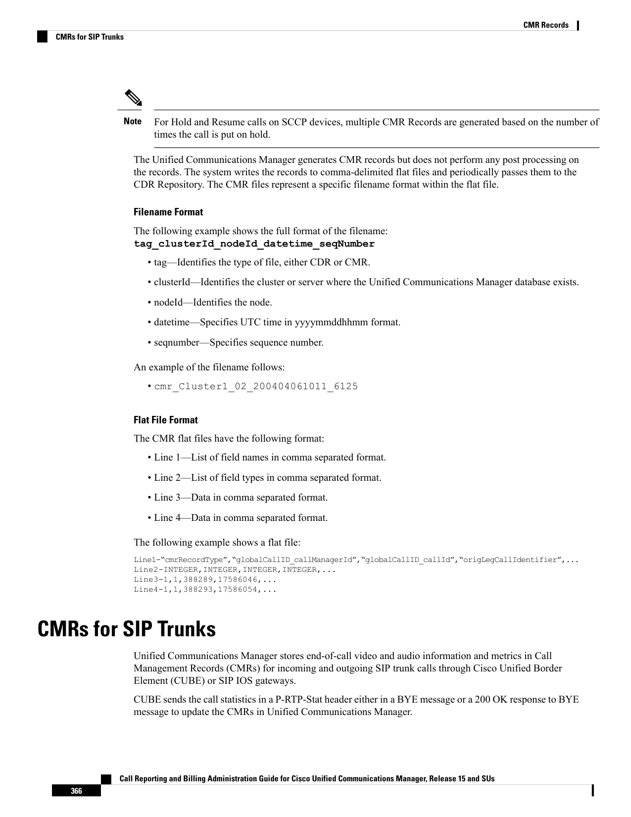
Page 379
When the call is routed through a Session Manager Edition (SME), call statistics sent by CUBE are recorded
in the CMRs generated on the SME than the LEAF cluster.
CMRs are generated by Unified Communications Manager when Call Diagnostics Enabled service parameter
is enabled.
Note
P-RTP Stat Format
The format of P-RTP-Stat is as follows:
P-RTP-Stat: PS=<Packets Sent>, OS=<Octets Sent>, PR=<Packets Recd>, OR=<Octets Recd>, PL=<Packets
Lost>, JI=<Jitter>, LA=<Round Trip Delay in ms>, DU=<Call Duration in seconds>
The following table describes the P-RTP-Stat header fields:
Table 101: P-RTP-Stat Header Fields
Description
Field
Packets Sent
PS
Octets Sent
OS
Packets Received
PR
Octets Received
OR
Packets Lost
PL
Jitter
JI
Round-Trip Delay in milliseconds (ms)
LA
Call Duration in seconds
DU
Example
The following example shows the sample BYE message with a P-RTP-Stat header.
Sample BYE Message
BYE sip:45002@209.165.201.1:5060;transport=tcp SIP/2.0
Via: SIP/2.0/TCP 209.165.200.225:5060;branch=z9hG4bK1a2f5c92d361
From:sip:1006@209.165.200.225;tag=12734~95fd5a73-11ac-4642-9308-401b17a658fb-17711590
To:<sip:45002@209.165.201.1;tag=445~b5883d68-042a-4a73-adc3-6be8a5f9f263-25068153
Date: Fri, 13 Oct 2017 04:29:38 GMT
Call-ID: 1e4d2a80-9e014132-6e2-e11f4d0a@209.165.200.225
User-Agent: Cisco-CUCM12.5
P-Asserted-Identity: sip:1006@209.165.200.225
CSeq: 102 BYE
Reason: Q.850;cause=16
Session-ID: 97173553334349d0a9391305caa12733;remote=49fd996b345a4745b9db7f242ddaa446
Content-Length: 0
P-RTP-Stat: PS=3775,OS=649300,PR=3775,OR=604000,PL=0,JI=0,LA=4,DU=98
Call Reporting and Billing Administration Guide for Cisco Unified Communications Manager, Release 15 and SUs
367
CMR Records
CMRs for SIP Trunks

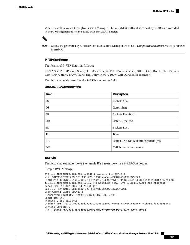
Page 380
Corresponding Sample Call Management Records
"cdrRecordType","globalCallID_callManagerId","globalCallID_callId","nodeId","directoryNum",
"callIdentifier","dateTimeStamp","numberPacketsSent","numberOctetsSent","numberPacketsReceived"
"numberOctetsReceived","numberPacketsLost","jitter","latency","pkid","directoryNumPartition",
"globalCallId_ClusterID","deviceName","varVQMetrics","duration","videoContentType","videoDuration",
"numberVideoPacketsSent","numberVideoOctetsSent","numberVideoPacketsReceived","numberVideoOctetsReceived",
"numberVideoPacketsLost","videoAverageJitter","videoRoundTripTime","videoOneWayDelay","videoReceptionMetrics",
"videoTransmissionMetrics","videoContentType_channel2","videoDuration_channel2","numberVideoPacketsSent_channel2",
"numberVideoOctetsSent_channel2","numberVideoPacketsReceived_channel2","numberVideoOctetsReceived_channel2",
"numberVideoPacketsLost_channel2","videoAverageJitter_channel2","videoRoundTripTime_channel2","videoOneWayDelay_channel2",
"videoReceptionMetrics_channel2","videoTransmissionMetrics_channel2"
INTEGER,INTEGER,INTEGER,INTEGER,VARCHAR(50),
INTEGER,INTEGER,INTEGER,INTEGER,INTEGER,INTEGER,INTEGER,INTEGER,INTEGER,UNIQUEIDENTIFIER,VARCHAR(50),VARCHAR(50),
VARCHAR(129),VARCHAR(600),INTEGER,VARCHAR(10),INTEGER,INTEGER,INTEGER,INTEGER,INTEGER,INTEGER,INTEGER,INTEGER,
INTEGER,VARCHAR(600),VARCHAR(600),VARCHAR(10),INTEGER,INTEGER,INTEGER,INTEGER,INTEGER,INTEGER,INTEGER,INTEGER,INTEGER,
VARCHAR(600),VARCHAR(600)
2,1,48553,1,"",29258891,1515145049,3775,649300,3775,604000,0,0,4,"50870a6d-193d-478f-8971-0dc641a6058a",
"","StandAloneCluster","sip_trunk3_to_camserv_2_DO","",98,"",,,,,,,,,,"","","",,,,,,,,,,"",""
2,1,48553,1,"11011",29258890,1515145049,8900,7676700,8998,7676767,0,2,0,"7526cf73-ae78-48b1-9640-7ea19b546321","",
"StandAloneCluster","SEPCD1111000011","",98,"main",0,0,0,0,0,0,0,0,0,"","TxFrameRate=0","",,,,,,,,,,"",""
In the preceding example, Unified Communications Manager inserts the call statistics into the CMRs per the
communicated information in the P-RTP-Stat header. If a P-RTP-Stat header comprises partial field values
or any field is absent, Unified Communications Manager generates CMRs with available field values.
Some of the fields in the CMRs are not populated due to fields unrelated to SIP trunk or if no call statistics
are received from CUBE.
Note
In the following scenarios, there are no CMRs written for the SIP trunk:
• P-RTP-Stat header is present without any fields in an incoming BYE message or 200 OK response to
BYE message from CUBE.
• P-RTP-Stat header is not present in an incoming BYE message or 200 OK response to BYE message
from CUBE.
• P-RTP-Stat header and fields are present in an incoming BYE message or 200 OK response to BYE
message from CUBE but corresponding field values are empty.
CMRs for Headsets
Unified Communications Manager stores the call diagnostics details for Headsets. The details include call
quality, packets lost, packets received, jitter, delay, and so on. Whenever there is a call between two phones
using headsets, the diagnostics records for both the headsets populates separately in a column ‘Headset-Stat’.
You can view the Serial Number and Metrics of the particular Headset used.
Example
The following example shows the sample BYE message for Headsets:
BYE sip:1@10.77.29.46:5060;transport=tcp SIP/2.0
RTP-TxStat: Dur=13,Pkt=658,Oct=105280
Call Reporting and Billing Administration Guide for Cisco Unified Communications Manager, Release 15 and SUs
368
CMR Records
CMRs for Headsets

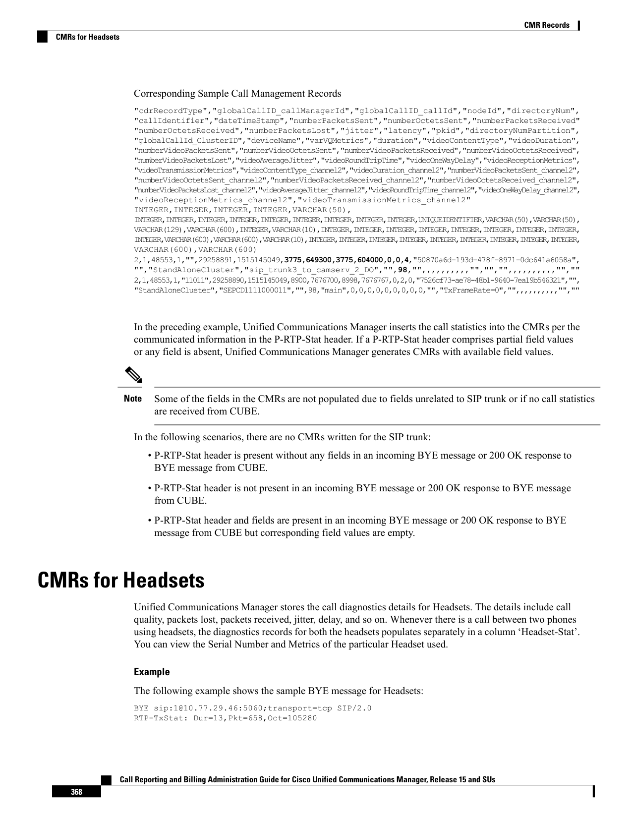
Page 381
Date: Thu, 10 Jan 2019 06:22:08 GMT
From: "1020" sip:1020@10.77.29.46;tag=e0899d9508fc00064e7fc5d0-264cc0f8
Content-Length: 0
User-Agent: Cisco-CP9971/9.4.2
User-Agent: Cisco-CP9971/9.4.2
To: sip:1@10.77.29.46;tag=38869~03b645d3-522f-428d-a380-425f3fdaed66-28473124
Call-ID: e0899d95-08fc0003-44f9a213-39b10eeb@10.77.36.21
Via: SIP/2.0/TCP 10.77.36.21:51918;branch=z9hG4bK7a47320e
CSeq: 102 BYE
Headset-Stat: SN=AAA111BBB222, Metrics="Key=value;Key1=Value1Key=value;"
Max-Forwards: 70
RTP-RxStat:
Dur=13,Pkt=657,Oct=113004,LatePkt=0,LostPkt=0,AvgJit=1,VQMetrics="MLQK=4.5000;MLQKav=4.5000;
MLQKmn=4.5000;MLQKmx=4.5000;MLQKvr=0.95;CCR=0.0000;ICR=0.0000;ICRmx=0.0000;CS=0;SCS=0"
CMRs for Headsets
Unified Communications Manager stores the call diagnostics details for Headsets. The details include call
quality, packets lost, packets received, jitter, delay, and so on. Whenever there is a call between two phones
using headsets, the diagnostics records for both the headsets populates separately in a column ‘Headset-Stat’.
You can view the Serial Number and Metrics of the particular Headset used.
Example
The following example shows the sample BYE message for Headsets:
BYE sip:1@10.77.29.46:5060;transport=tcp SIP/2.0
RTP-TxStat: Dur=13,Pkt=658,Oct=105280
Date: Thu, 10 Jan 2019 06:22:08 GMT
From: "1020" sip:1020@10.77.29.46;tag=e0899d9508fc00064e7fc5d0-264cc0f8
Content-Length: 0
User-Agent: Cisco-CP9971/9.4.2
User-Agent: Cisco-CP9971/9.4.2
To: sip:1@10.77.29.46;tag=38869~03b645d3-522f-428d-a380-425f3fdaed66-28473124
Call-ID: e0899d95-08fc0003-44f9a213-39b10eeb@10.77.36.21
Via: SIP/2.0/TCP 10.77.36.21:51918;branch=z9hG4bK7a47320e
CSeq: 102 BYE
Headset-Stat: SN=AAA111BBB222, Metrics="Key=value;Key1=Value1Key=value;"
Max-Forwards: 70
RTP-RxStat:
Dur=13,Pkt=657,Oct=113004,LatePkt=0,LostPkt=0,AvgJit=1,VQMetrics="MLQK=4.5000;MLQKav=4.5000;
MLQKmn=4.5000;MLQKmx=4.5000;MLQKvr=0.95;CCR=0.0000;ICR=0.0000;ICRmx=0.0000;CS=0;SCS=0"
Set Up CMRs
You can configure CMRs on the Service Parameters Configuration window in Cisco Unified CM
Administration.
1.
To access the Service Parameters Configuration window, open Cisco Unified CM Administration and
choose System > Service Parameters.
2.
Choose Advanced button.
3.
Select the Call Diagnostics Enabled parameter.
Call Reporting and Billing Administration Guide for Cisco Unified Communications Manager, Release 15 and SUs
369
CMR Records
CMRs for Headsets
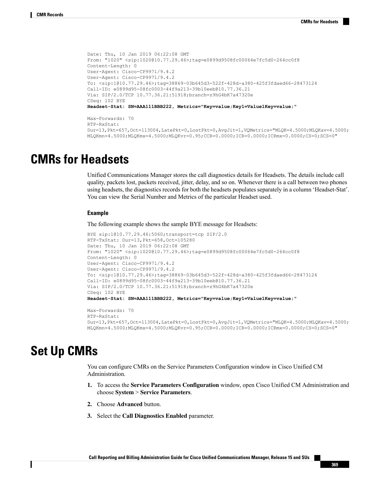
Page 382
This parameter determines whether the system generates CMRs, also called call diagnostic records. Valid
values specify Disabled (do not generate CMRs), Enabled Only When CDR Enabled Flag is True (generate
CMRs only when the CDR Enabled Flag service parameter is set to True), or Enabled Regardless of CDR
Enabled Flag (generates CMRs without regard to the setting in the CDR Enabled Flag service parameter).
This represents a required field. The default value specifies Disabled.
Feature Limitations
This feature is not supported for SME call flows:
• On receiving call statistics from CUBE/IOS GW on SME, Unified Communications Manager generates
CMR (provided CMR is enabled) for the trunk side, but it won’t be able to forward call statistics to other
nodes in outgoing BYE or 200OK for BYE.
• Sample Call flow:
Phone1 > CUBE/IOS GW > SME > CUCM1 > Phone2
For the above call scenario, SME generates the CMR for trunk side pointing to CUBE. These statistics
are not forwarded to a leaf node. For Phone2, CMR is recorded on a leaf node.
CPU Utilization
Cisco has performed basic testing to measure CPU utilization when CDRs and/or CMRs are enabled. The
CPU utilization testing was measured on subscribers and was not measured on the publishers. Your actual
results can vary because of the CDR Loader settings and the CDR Management settings for external billing
servers. The following table displays the results of these tests.
These tests were performed with Unified Communications Manager Release 8.0(1).
Note
Table 102: CDR and CMR CPU Utilization
% Increase in
CPU
% Increase in Cisco
Unified CM CPU
Average % Increase
in Total CPU
Utilization
Average % Increase
in Cisco Unified CM
CPU Utilization
CDRs and CMRs Enabled/Disabled
11.15
6.17
CDRs disabled, CMRs disabled
8.57
13.18
12.10
6.99
CDRs enabled, CMRs disabled
0.86
3.43
11.24
6.38
CDRs disabled, CMRs enabled
17.02
24.92
13.04
7.71
CDRs enabled, CMRs enabled
Call Reporting and Billing Administration Guide for Cisco Unified Communications Manager, Release 15 and SUs
370
CMR Records
CPU Utilization

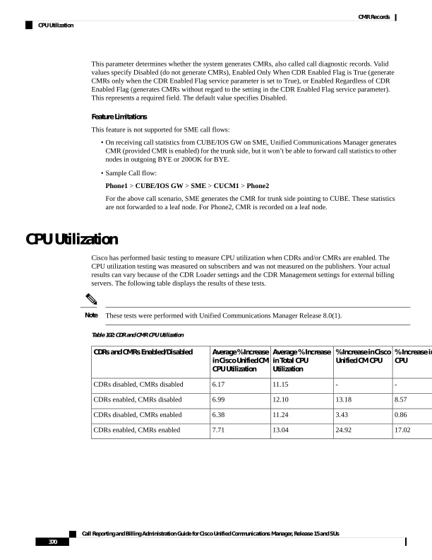
Page 383
C H A P T E R 12
CMR Field Descriptions
This chapter describes the field descriptions of the Call Management Records (CMRs).
• CMR Field Descriptions, on page 371
• K-Factor Data, on page 380
CMR Field Descriptions
The following table contains the fields, range of values, and field descriptions of the CMRs in the order in
which they appear in the CMR.
Table 103: CMR Field Descriptions
Description
Range of Values
Field Name
Specifies the type of this specific record. The following valid
values apply:
• 0—Start call detail record (not used)
• 1—End call detail record
• 2—CMR record
Default - For CMRs, this field always specifies 2.
0, 1, or 2
cdrRecordType
Specifies a unique Unified Communications Manager identity.
This field makes up half of the Global Call ID. The Global Call
ID comprises the following fields:
• globalCallId_callId
• globalCallID_callManagerID
All records that are associated with a standard call have the same
Global Call ID in them.
Default - Ensure that this field is populated.
Positive Integer
globalCallID_callManagerId
Call Reporting and Billing Administration Guide for Cisco Unified Communications Manager, Release 15 and SUs
371

Page 384
Description
Range of Values
Field Name
Specifies a unique call identity value that gets assigned to each
call. The system allocates this identifier independently on each
call server. Values get chosen sequentially when a call begins.
Each call, successful or unsuccessful, receives value assignment.
This field makes up half the Global Call ID. The Global Call ID
comprises the following two fields:
• globalCallId_callId
• globalCallID_callManagerID
All records that are associated with a standard call have the same
Global Call ID in them.
Default - Ensure that this field is populated.
Positive Integer
globalCallId_callId
Specifies the server or node within the Unified Communications
Manager cluster, where this record gets generated.
Default - Ensure that this field is populated.
Positive Integer
nodeId
Specifies the directory number of the device from which these
diagnostics are collected.
Default - Ensure that this field is populated.
Integer
directoryNumber
Identifies the call leg to which this record pertains.
Default - Ensure that this field is populated.
Positive Integer
callIdentifier
Represents the approximate time that the device goes on the hook.
Unified Communications Manager records the time when the
phone responds to a request for diagnostic information.
Default - Ensure that this field is populated.
Integer
dateTimeStamp
Designates the total number of Routing Table Protocol (RTP)
data packets that the device transmits since starting transmission
on this connection. The value remains zero if the connection is
set to “receive only” mode.
Default - 0
Integer
numberPacketsSent
Specifies the total number of payload octets (that is, not including
header or padding) that the device transmits in RTP data packets
since starting transmission on this connection. The value remains
zero if the connection is set to “receive only” mode.
Default - 0
Integer
numberOctetsSent
Call Reporting and Billing Administration Guide for Cisco Unified Communications Manager, Release 15 and SUs
372
CMR Records
CMR Field Descriptions
Page 385
Description
Range of Values
Field Name
Specifies the total number of RTP data packets that the device
has received since starting reception on this connection. The count
includes packets that are received from different sources if this
is a multicast call. The value remains zero if the connection is set
in “send only” mode.
Default - 0
Integer
numberPacketsReceived
Specifies the total number of payload octets (that is, not including
header or padding) that the device has received in RTP data
packets since starting reception on this connection. The count
includes packets that are received from different sources if this
is a multicast call. The value remains zero if the connection is set
in “send only” mode.
Default - 0
Integer
numberOctetsReceived
Designates the total number of RTP data packets that have been
lost since the beginning of reception. This number designates the
number of packets that were expected, less the number of packets
that were received, where the number of packets that were received
includes any that are late or duplicates. Thus, packets that arrive
late do not get counted as lost, and the loss may be negative if
duplicate packets exist. The number of packets that are expected
designates the extended last sequence number that was received,
as defined next, less the initial sequence number that was received.
The value remains zero if the connection was set in “send only”
mode. For detailed information, see RFC 1889.
Default - 0
Integer
numberPacketsLost
Provides an estimate of the statistical variance of the RTP data
packet interarrival time that is measured in milliseconds and
expressed as an unsigned integer. The interarrival jitter J specifies
the mean deviation (smoothed absolute value) of the difference
D in the packet spacing at the receiver, compared to the sender
for a pair of packets. RFC 1889 contains detailed computation
algorithms. The value remains zero if the connection was set in
“send only” mode.
Default - 0
Integer
jitter
Call Reporting and Billing Administration Guide for Cisco Unified Communications Manager, Release 15 and SUs
373
CMR Records
CMR Field Descriptions
Page 386
Description
Range of Values
Field Name
Designates value that is an estimate of the network latency,
expressed in milliseconds. This value represents the average value
of the difference between the NTP timestamp that the RTP Control
Protocol (RTCP) messages indicate and the NTP timestamp of
the receivers, measured when these messages are received. Unified
Communications Manager obtains the average by summing all
estimates then dividing by the number of RTCP messages that
have been received. For detailed information, see RFC 1889.
Default - 0
Note
CMR records will not show latency for all phone loads. For
example, for SIP 9.2.1 and 9.2.2, the latency will not show, as it
has not been implemented in these loads.
Integer
latency
Identifies a text string that the database uses internally to uniquely
identify each row. This text string provides no meaning to the call
itself.
Default - The system always populates this field with a unique
ID.
Text String
pkid
Identifies the partition of the directory number.
Default - Empty string “”. This field may remain empty if no
partition exists.
Text String
directoryNumberPartition
Designates a unique ID that identifies a single Unified
Communications Manager, or a cluster of Unified
Communications Managers.
The system generates this field during installation, but Unified
Communications Manager does not use it: globalCallId_ClusterId
- globalCallId_callManagerId + globalCallId_callId.
Default - Ensure that this field is populated.
Text String
globalCallId_ClusterId
Identifies the name of the device.
Default - Empty string “”. This field may remain empty if no
device name exists.
Text String
deviceName
Call Reporting and Billing Administration Guide for Cisco Unified Communications Manager, Release 15 and SUs
374
CMR Records
CMR Field Descriptions
Page 387
Description
Range of Values
Field Name
Contains a variable number of voice quality metrics. This field
comprises a string of voice quality metrics that are separated by
a semicolon.
The format of the string follows:
fieldName=value;fieldName=value.precision
This example shows voice quality data, but the names may differ.
"MLQK=4.5000;MLQKav=4.5000;
MLQKmn=4.5000;MLQKmx=4.5000;MLQKvr=0.95;
CCR=0.0000;ICR=0.0000;ICRmx=0.0000; CS=0;SCS=0”
Note
For more information on the K-Factor data that makes up the
varVQMetrics record, see K-Factor Data, on page 380.
Text String
varVQMetrics
Specifies the duration value of audio session that is expressed in
seconds. This is reported only for SIP phones.
Integer
duration
Identifies the type of video stream. It can be “main”, “speaker”
or “slides”. For an audio-only call, no video metrics are populated.
Text String
videoContentType
Specifies the duration value of the first video session, expressed
in seconds.
Integer
videoDuration
Specifies the total number of RTP data packets that are transmitted
by the device since starting transmission on this connection.
Integer
numberVideoPacketsSent
Specifies the total number of payload octets (that is, not including
header or padding) transmitted in RTP data packets by the device
since starting transmission on this connection.
Integer
numberVideoOctetsSent
Specifies the total number of RTP data packets received by the
device since starting reception on this connection.
Integer
numberVideoPacketsReceived
Specifies the total number of payload octets (that is, not including
header or padding) received in RTP data packets by the device
since starting reception on this connection.
Integer
numberVideoOctetsReceived
Specifies the total number of RTP data packets that have been
lost since the beginning of reception on this connection.
Integer
numberVideoPacketsLost
Provides an estimate of the statistical variance of the RTP data
packet interarrival time for this connection that is measured in
milliseconds and expressed as an unsigned integer. For detailed
information, see RFC 3550 for details.
Integer
videoAverageJitter
This is a measure of average round trip time between the two
endpoints for this connection. It is expressed in milliseconds. For
detailed information, see RFC 3550 and RFC 3611 for detail
Integer
videoRoundTripTime
Call Reporting and Billing Administration Guide for Cisco Unified Communications Manager, Release 15 and SUs
375
CMR Records
CMR Field Descriptions
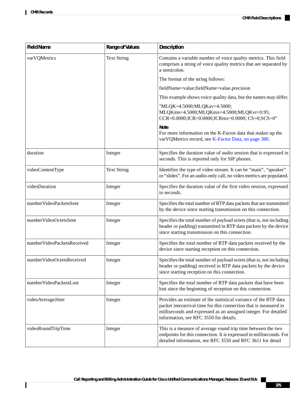
Page 388
Description
Range of Values
Field Name
This is a measure of the average one-way delay (OWD) between
the endpoints for this connection. This is only available if
endpoints are time synchronized (same NTP source) and is
measured in milli-seconds; otherwise “NA”
Text String
videoOneWayDelay
Contains a variable number of Cisco defined metrics that are
related to RTP transmission on this connection. These metrics are
delimited by a semicolon. The format of this string is:
CiscoTxVM="TxCodec=xxx; TxBw=xxx;TxBwMax=xxx;
TxReso=xxx;TxFrameRate=xxx"
TxCodec identifies the type of video codec used for the transmitted
video stream.
TxBw identifies the actual bandwidth that is used for the
transmitted video stream.
TxBwMax identifies the maximum negotiated bandwidth for the
transmitted video stream.
TxReso identifies the resolution of the transmitted video stream
(for example, 640x480).
TxFrameRate identifies the average frame rate that is measured
in frames per second for the transmitted video stream.
Text String
videoTransmissionMetrics
Call Reporting and Billing Administration Guide for Cisco Unified Communications Manager, Release 15 and SUs
376
CMR Records
CMR Field Descriptions
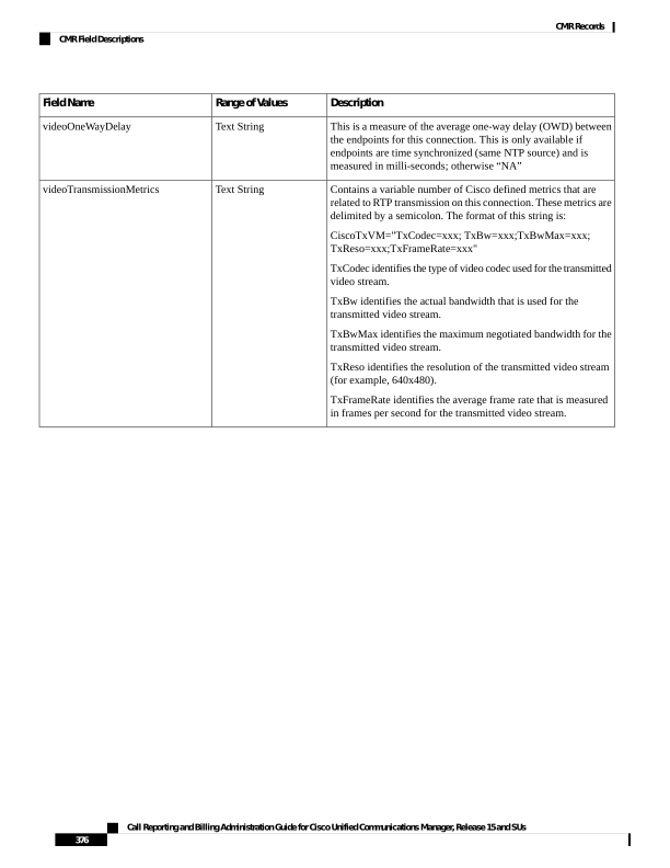
Page 389
Description
Range of Values
Field Name
Contains a variable number of Cisco defined metrics that are
related to RTP reception on this connection. These metrics are
delimited by a semicolon. The format of this string is:
CiscoRxVM="CS=xxx; SCS=xxx;DSCP=xxx; DSCPunad=xxx;
RxFramesLost=xxx;RxCodec=xxx; RxBw=xxx;RxBwMax=xxx;
RxReso=xxx;RxFrameRate=xxx"
CS identifies the concealed seconds metrics for the received video
stream.
SCS identifies the severely concealed seconds for the received
video stream.
DSCP is useful in verifying the DSCP value of the received video
stream marked by endpoint.
DSCPunad is useful in verifying the DSCP value of the received
video stream marked by endpoint.
RxCodec identifies the type of video codec used for received
video stream.
RxBw identifies the actual bandwidth used for the received video
stream.
RxBwMax identifies the maximum negotiated bandwidth for the
received video stream.
RxReso identifies the resolution of the received video stream (for
example, 640x480).
RxFrameRate identifies the average frame rate measured in frames
per second for the received video stream.
TextString
videoReceptionMetrics
Identifies the type of second video stream if it exists. If it does
not exist, the remaining metrics for the second video stream will
not be populated.
Text String
videoContentType_channel2
Specifies the duration of the second video session, expressed in
seconds.
Integer
videoDuration_channel2
Specifies the total number of RTP data packets that are transmitted
by the device since starting transmission on this connection.
Integer
numberVideoPacketsSent_channel2
Specifies the total number of payload octets (that is, not including
header or padding) transmitted in RTP data packets by the device
since starting transmission on this connection.
Integer
numberVideoOctetsSent_channel2
Specifies the total number of RTP data packets received by the
device since starting reception on this connection.
Integer
numberVideoPacketsReceived_channel2
Specifies the total number of payload octets (that is, not including
header or padding) received in RTP data packets by the device
since starting reception on this connection.
Integer
numberVideoOctetsReceived_channel2
Call Reporting and Billing Administration Guide for Cisco Unified Communications Manager, Release 15 and SUs
377
CMR Records
CMR Field Descriptions
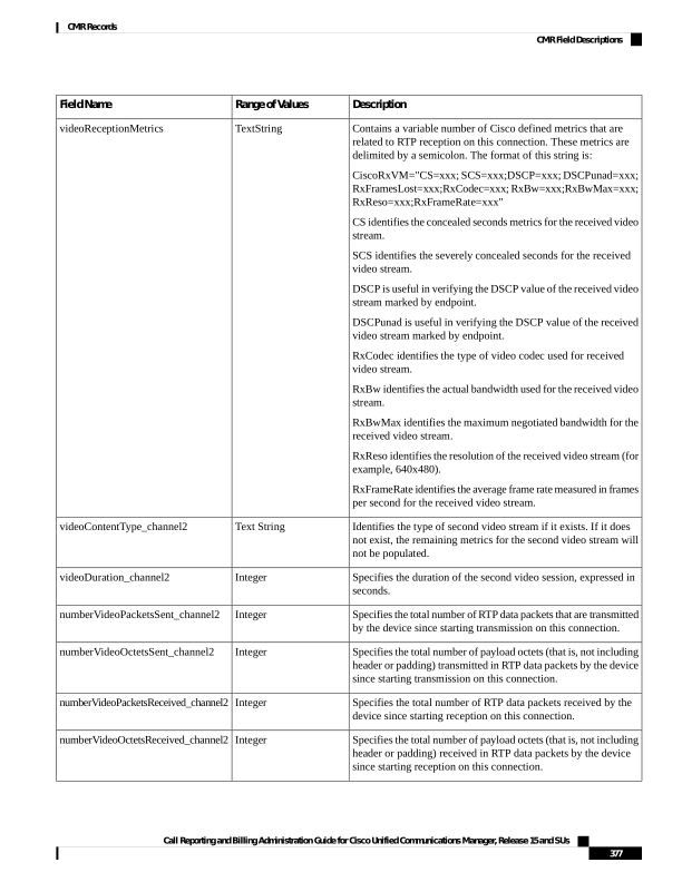
Page 390
Description
Range of Values
Field Name
The total number of RTP data packets that have been lost since
the beginning of reception on this connection.
Integer
numberVideoPacketsLost_channel2
Provides an estimate of the statistical variance of the RTP data
packet interarrival time for this connection that is measured in
milliseconds and expressed as an unsigned integer. For more
information, see RFC 3550.
Integer
videoAverageJitter_channel2
This is a measure of average round trip time between the two
endpoints for this connection. It is expressed in milliseconds. For
more information, see RFC 3550 and RFC 3611 for details.
Integer
videoRoundTripTime_channel2
This is a measure of the average one-way delay (OWD) between
the endpoints for this connection. This is only available if
endpoints are time synchronized (same NTP source) and is
measured in milli-seconds; otherwise “NA”.
Integer
videoOneWayDelay_channel2
Contains a variable number of Cisco defined metrics that are
related to RTP transmission on this connection. These metrics are
delimited by a semicolon. The format of this string is:
CiscoTxVM="TxCodec=xxx; TxBw=xxx ;TxBwMax=xxx;
TxReso=xxx;TxFrameRate=xxx"
TxCodec identifies the type of video codec used for the transmitted
video stream.
TxBw identifies the actual bandwidth used for the transmitted
video stream.
TxBwMax identifies the maximum negotiated bandwidth for the
transmitted video stream.
TxReso identifies the resolution of the transmitted video stream
(for example, 640x480).
TxFrameRate identifies the average frame rate measured in frames
per second for the transmitted video stream.
Text String
videoReceptionMetrics_channel2
Call Reporting and Billing Administration Guide for Cisco Unified Communications Manager, Release 15 and SUs
378
CMR Records
CMR Field Descriptions
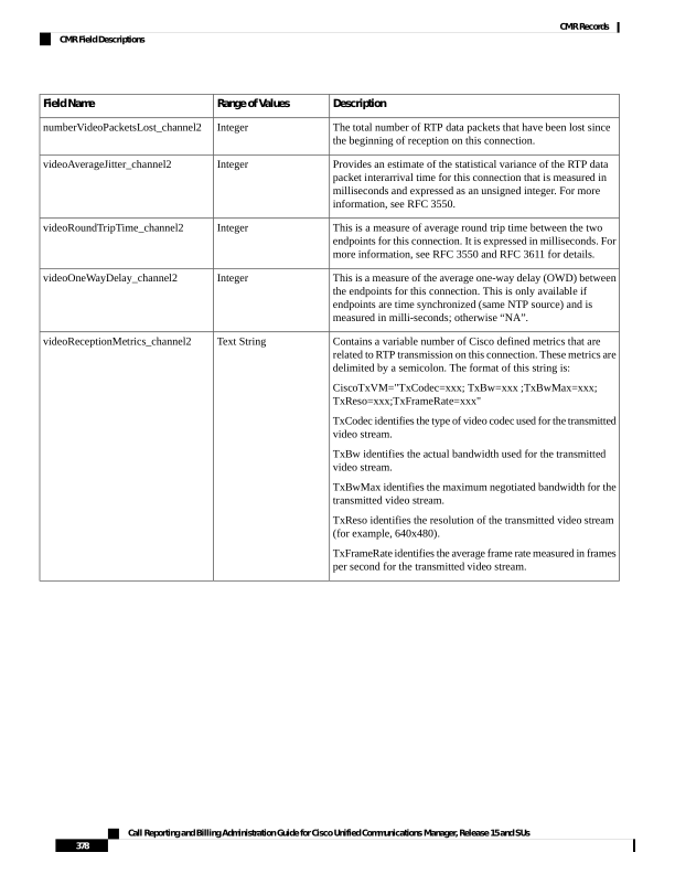
Page 391
Description
Range of Values
Field Name
Contains a variable number of Cisco defined metrics that are
related to RTP reception on this connection. These metrics are
delimited by a semicolon. The format of this string is:
CiscoRxVM="CS=xxx; SCS=xxx;DSCP=xxx; DSCPunad=xxx;
RxFramesLost=xxx;RxCodec=xxx; RxBw=xxx;RxBwMax=xxx;
RxReso=xxx;RxFrameRate=xxx"
CS identifies the concealed seconds metrics for the received video
stream.
SCS identifies the severely concealed seconds for the received
video stream.
DSCP is useful in verifying the DSCP value of the received video
stream that is marked by endpoint.
DSCPunad is useful in verifying the DSCP value of the received
video stream marked by endpoint.
RxCodec identifies the type of video codec used for the received
video stream.
RxBw identifies the actual bandwidth that is used for the received
video stream.
RxBwMax identifies the maximum negotiated bandwidth for the
received video stream.
RxReso identifies the resolution of the received video stream (for
example, 640x480).
RxFrameRate identifies the average frame rate that is measured
in frames per second for the received video stream.
Text String
videoTransmissionMetrics_channel2
Indicates call Session ID of the local device.
The system generates a CMR record for each call leg when the
user disconnects the call from the user device. This field is
populated with the local device Session ID of the particular call.
The maximum length of this field is restricted to 127 characters.
For example, localSessionlD = ab303 l
7fla784dc48fl824d0d3715d86
Text String
localSessionID
Indicates call Session ID of the remote device.
The system generates a CMR record for each call leg when the
user disconnects the call from the user device. This field is
populated with the remote device Session ID of the particular call.
The maximum length of this field is restricted to 127 characters.
For example, remoteSessionID =
47755a9de7794ba387653f2099600ef2
Text String
remoteSessionID
Call Reporting and Billing Administration Guide for Cisco Unified Communications Manager, Release 15 and SUs
379
CMR Records
CMR Field Descriptions
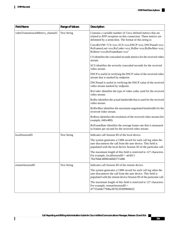
Page 392
Description
Range of Values
Field Name
Indicates the serial number of the headset used.
The system generates a CMR record for the headset used with the
phone and this field is populated with the serial number of the
headset.
The maximum length of this field is restricted to 129 characters.
For example, SN=AAA111BBB222
Integer
SN
Indicates the serial number of the headset used.
The system generates a CMR record for the headset used with the
phone and this field is populated with the serial number of the
headset.
The maximum length of this field is restricted to 129 characters.
For example, SN=AAA111BBB222
Integer
SN
Indicates the metrics of the particular headset used.
The system generates a CMR record for the headset used with the
phone and this field is populated with the diagnostics records of
the headset.
The maximum length of this field is restricted to 600 characters.
For example, Metrics="Key=value;Key1=Value1Key=value;"
Note
The sub-fields within the Metrics field are not validated.
Text String
Metrics
Indicates the metrics of the particular headset used.
The system generates a CMR record for the headset used with the
phone and this field is populated with the diagnostics records of
the headset.
The maximum length of this field is restricted to 600 characters.
For example, Metrics="Key=value;Key1=Value1Key=value;"
Note
The sub-fields within the Metrics field are not validated.
Text String
Metrics
K-Factor Data
K-factor represents an endpoint mean opinion score (MOS) estimation algorithm that is defined in ITU standard
P.VTQ. It represents a general estimator that is used to estimate the mean value of a perceptual evaluation of
speech quality (PESQ) population for a specific impairment pattern.
MOS relates to the output of a well designed listening experiment. All MOS experiments use a five-point
PESQ scale as defined in ITU standard P.862.1, which describes the PESQ as an objective method for
end-to-end speech quality assessment of narrow-band telephone networks and speech codecs.
Call Reporting and Billing Administration Guide for Cisco Unified Communications Manager, Release 15 and SUs
380
CMR Records
K-Factor Data
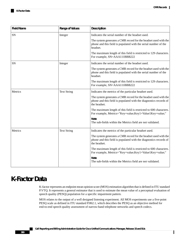
Page 393
The MOS estimate provides a number that is inversely proportional to frame loss density. Clarity decreases
as more frames are lost or discarded at the receiving end. Consider the loss or discarding of these frames as
concealment. Concealment statistics measure packet (frame) loss and its effect on voice quality in an impaired
network.
K-factor represents a weighted estimate of average user annoyance due to distortions that are caused by
effective packet loss such as dropouts and warbles. It does not estimate the impact of delay-related impairments
such as echo. It provides an estimate of listening quality (MOS-LQO) rather than conversational quality
(MOS-CQO), and measurements of average user annoyance range from 1 (poor voice quality) to 5 (very good
voice quality).
K-factor gets trained or conditioned by speech samples from numerous speech databases, where each training
sentence or network condition that is associated with a P.862.1 value has a duration of 8 seconds. For more
accurate scores, the system generates k-factor estimates for every 8 seconds of active speech.
Consider K-factor and other MOS estimators to be secondary or derived statistics because they warn a network
operator of frame loss only after the problem becomes significant. Packet counts, concealment ratios, and
concealment second counters represent primary statistics because they alert the network operator before
network impairment has an audible impact or is visible through MOS.
The following table displays the K-factor date that is stored in the Unified Communications Manager CMRs.
Table 104: K-Factor Data Stored in Unified Communications Manager CMRs
D&I User Interface Text and Description
Phone Display Name
Field Name
Cumulative Conceal Ratio represents the cumulative
ratio of concealment time over speech time that is
observed after starting a call.
Cum Conceal Ratio
CCR
Interval Conceal Ratio represents an interval-based
average concealment rate that is the ratio of
concealment time over speech time for the last 3
seconds of active speech.
Interval Conceal Ratio
ICR
Interval Conceal Ratio Max represents the
maximum concealment ratio that is observed during
the call.
Max Conceal Ratio
ICRmx
Conceal Secs represents the time during which some
concealment is observed during a call.
Conceal Secs
CS
Severely Conceal Secs represents the time during
which a significant amount of concealment is
observed. If the concealment that is observed is
usually greater than 50 milliseconds or
approximately 5 percent, the speech probably does
not seem very audible.
Severely Conceal Secs
SCS
MOS Listening Quality K-factor provides an
estimate of the MOS score of the last 8 seconds of
speech on the reception signal path.
MOS LQK
MLQK
Call Reporting and Billing Administration Guide for Cisco Unified Communications Manager, Release 15 and SUs
381
CMR Records
K-Factor Data
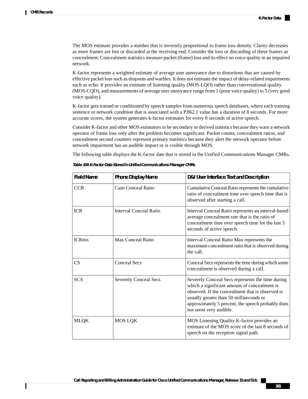
Page 394
D&I User Interface Text and Description
Phone Display Name
Field Name
MOS Listening Quality K-factor Min represents
the minimum score that is observed since the
beginning of a call and represents the worst
sounding 8-second interval.
Min MOS LQK
MLQKmn
MOS Listening Quality K-factor Max represents
the maximum score that is observed since the
beginning of a call and represents the best sounding
8-second interval.
Max MOS LQK
MLQKmx
MOS Listening Quality K-factor Avg8 represents
the running average of scores that are observed
since the beginning of a call.
Avg MOS LQK
MLQKav
Related Topics
Call Management Records
Cisco Call Management Record Field Descriptions
Documentation Related to CDR
Example Cisco Call Management Records
Call Reporting and Billing Administration Guide for Cisco Unified Communications Manager, Release 15 and SUs
382
CMR Records
K-Factor Data
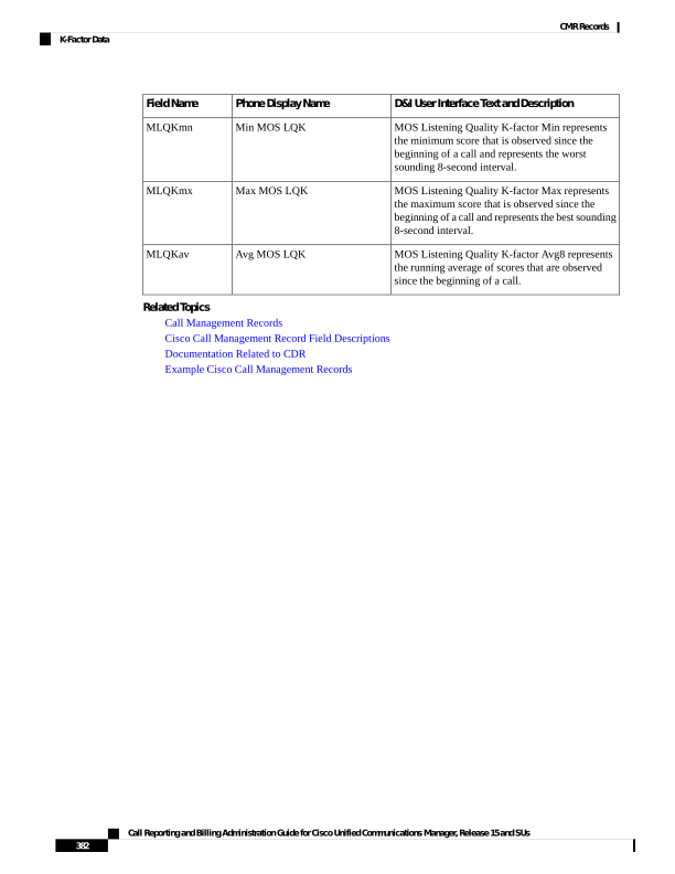
Page 395
C H A P T E R 13
CMR Examples
This chapter provides examples of call management records (CMRs).
• CMR Examples, on page 383
CMR Examples
The following examples of CMRs get generated during a normal call (IP phone to IP phone). Normal calls
log three records per call: one CDR and two CMRs (one for each endpoint).
These examples represent a call between directory number 1010 and 1014. See related topics for a sample of
the CDR that gets generated during a normal call.
Example 1: SCCP to SCCP Phone
A successful call between two Cisco IP Phones generates 2 CMRs at the end of the call, one for each endpoint.
This example has both endpoints as SCCP phones that do not support the new video metrics. They are left at
default.
“Duration” field in CMR is filled only for SIP phones.
Note
CMR 1
Values
Field Names
2
cdrRecordType
1
globalCallID_callManagerId
96004
globalCallID_callId
1
nodeId
1010
directoryNum
28141535
callIdentifier
Call Reporting and Billing Administration Guide for Cisco Unified Communications Manager, Release 15 and SUs
383


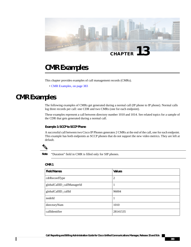
Page 396
Values
Field Names
1202412060
dateTimeStamp
358
numberPacketsSent
61576
numberOctetsSent
351
numberPacketsReceived
60372
numberOctetsReceived
1
numberPacketsLost
0
jitter
0
latency
e95df5b1-2914-4a03-befb-0f58bf16392d
pkid
directoryNumPartition
StandAloneCluster
globalCallIdClusterID
SEP003094C39BE7
deviceName
MLQK=0.0000;MLQKav=0.0000;
MLQKmn=0.0000;MLQKmx=0.0000;MLQKvr=0.95;
CCR=0.0000;ICR=0.0000;ICRmx=0.0000;CS=0;
SCS=0
varVQMetrics
duration
videoContentType
videoDuration
numberVideoPacketsSent
numberVideoOctetsSent
numberVideoPacketsReceived
numberVideoOctetsReceived
numberVideoPacketsLost
videoAverageJitter
videoRoundTripTime
videoOneWayDelay
videoReceptionMetrics
videoTransmissionMetrics
Call Reporting and Billing Administration Guide for Cisco Unified Communications Manager, Release 15 and SUs
384
CMR Records
CMR Examples
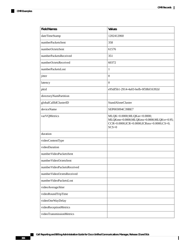
Page 397
Values
Field Names
videoContentType_channel2
videoDuration_channel2
numberVideoPacketsSent_channel2
numberVideoOctetsSent_channel2
numberVideoPacketsReceived_channel2
numberVideoOctetsReceived_channel2
numberVideoPacketsLost_channel2
videoAverageJitter_channel2
videoRoundTripTime_channel2
videoOneWayDelay_channel2
videoReceptionMetrics_channel2
videoTransmissionMetrics_channel2
CMR 2
Values
Field Name
2
cdrRecordType
1
globalCallID_callManagerId
96004
globalCallID_callId
1
nodeId
1004
directoryNum
28141536
callIdentifier
1202412060
dateTimeStamp
352
numberPacketsSent
60544
numberOctetsSent
356
numberPacketsReceived
61232
numberOctetsReceived
1
numberPacketsLost
0
jitter
Call Reporting and Billing Administration Guide for Cisco Unified Communications Manager, Release 15 and SUs
385
CMR Records
CMR Examples
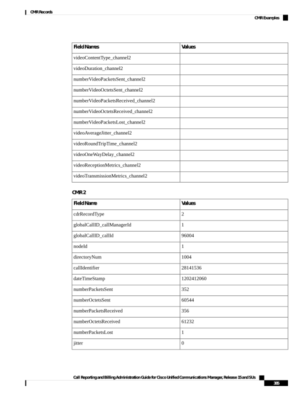
Page 398
Values
Field Name
0
latency
545ff25a-5475-4882-af09-c7b714802703
pkid
directoryNumPartition
StandAloneCluster
globalCallIdClusterID
SEP0007EBBA6376
deviceName
MLQK=0.0000;MLQKav=0.0000;
MLQKmn=0.0000;
MLQKmx=0.0000;MLQKvr=0.95; CCR=0.0000;
ICR=0.0000;ICRmx=0.0000;CS=0; SCS=0
varVQMetrics
duration
videoContentType
videoDuration
numberVideoPacketsSent
numberVideoOctetsSent
numberVideoPacketsReceived
numberVideoOctetsReceived
numberVideoPacketsLost
videoAverageJitter
videoRoundTripTime
videoOneWayDelay
videoReceptionMetrics
videoTransmissionMetrics
videoContentType_channel2
videoDuration_channel2
numberVideoPacketsSent_channel2
numberVideoOctetsSent_channel2
numberVideoPacketsReceived_channel2
numberVideoOctetsReceived_channel2
numberVideoPacketsLost_channel2
Call Reporting and Billing Administration Guide for Cisco Unified Communications Manager, Release 15 and SUs
386
CMR Records
CMR Examples
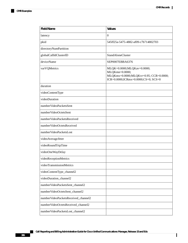
Page 399
Values
Field Name
videoAverageJitter_channel2
videoRoundTripTime_channel2
videoOneWayDelay_channel2
videoReceptionMetrics_channel2
videoTransmissionMetrics_channel2
Example 2: SIP to SIP Phone That Supports Main Video Metrics
The following CMR flat file is an example of SIP to SIP phone that supports video metrics.
Values
Field Name
2
cdrRecordType
1
globalCallID_callManagerId
17001
globalCallID_callId
1
nodeId
139098
directoryNum
32216238
callIdentifier
1379591701
dateTimeStamp
170
numberPacketsSent
10370
numberOctetsSent
169
numberPacketsReceived
12337
numberOctetsReceived
0
numberPacketsLost
2
jitter
0
latency
ea0cddd0-7ddd-4a4e-a697-ca405e39292c
pkid
directoryNumPartition
StandAloneCluster
globalCallId_ClusterID
SEPD0C7891411C3
deviceName
Call Reporting and Billing Administration Guide for Cisco Unified Communications Manager, Release 15 and SUs
387
CMR Records
CMR Examples
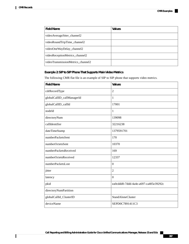
Page 400
Values
Field Name
MLQK=0.0000;MLQKav=0.0000;MLQKmn=0.0000;
MLQKmx=0.0000;MLQKvr=;CCR=0.0000;ICR=0.0000;
ICRmx=0.0000;CS=0;SCS=0
varVQMetrics
3
duration
main
videoContentType
3
videoDuration
140
numberVideoPacketsSent
126355
numberVideoOctetsSent
141
numberVideoPacketsReceived
128214
numberVideoOctetsReceived
0
numberVideoPacketsLost
7
videoAverageJitter
0
videoRoundTripTime
0
videoOneWayDelay
RxCodec=H264;RxBw=377;RxReso=640x360;
RxFrameRate=31;RxFramesLost=0
videoReceptionMetrics
TxCodec=H264;TxBw=368;TxReso=640x360;
TxFrameRate=30
videoTransmissionMetrics
videoContentType_channel2
videoDuration_channel2
numberVideoPacketsSent_channel2
numberVideoOctetsSent_channel2
numberVideoPacketsReceived_channel2
numberVideoOctetsReceived_channel2
numberVideoPacketsLost_channel2
videoAverageJitter_channel2
videoRoundTripTime_channel2
videoOneWayDelay_channel2
videoReceptionMetrics_channel2
Call Reporting and Billing Administration Guide for Cisco Unified Communications Manager, Release 15 and SUs
388
CMR Records
CMR Examples
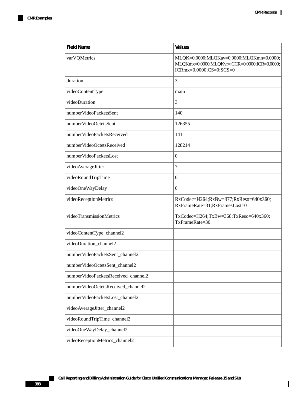
Page 401
Values
Field Name
videoTransmissionMetrics_channel2
Call Reporting and Billing Administration Guide for Cisco Unified Communications Manager, Release 15 and SUs
389
CMR Records
CMR Examples

Page 402
Call Reporting and Billing Administration Guide for Cisco Unified Communications Manager, Release 15 and SUs
390
CMR Records
CMR Examples