Document Metadata
Format: PDF
Title: Understand IOS and IOS XE Call Routing
Page 1
Understand IOS and IOS XE Call Routing
Contents
Introduction
Prerequisites
Requirements
Components Used
Background Information
Common Definitions
Command and Feature Roadmap
Cisco IOS / Cisco IOS XE Call Routing Fundamentals
Voice Dial-Peer Types
Inbound Dial-Peer Matching
When No Matches Exist /Default Dial-Peer 0 peer_tag=0, pid:0
Outbound Dial-Peer Matching
Number String Dial-Peer Hunting
URI Dial-Peer Hunting
Voice Class URI
Inbound URI Dial-Peer Matching
Common Use Cases
Configuration Example
Outbound URI Dial-Peer Matching
Configuration Example
Configuration Example
Dial-Peer Wildcards
Dial-Peer States
Virtual Routing and Forwarding (VRF) and Dial-Peer Hunting
Inbound Dial-Peer Matching with VRF
Outbound Dial-Peer Matching with VRF
VRF and Dial-Peer Group Configuration Example
Advanced Call Routing Techniques
Dial-Peer Groups
Configuration Example
E164-Pattern-Maps
CLI Configuration Example - Calling Numbers
CLI Configuration Example - Called Number
Flash Configuration Example
Destination Server-Groups
Configuration Example - Normal
Destination Server Group and OPTIONS Keepalive
Outbound Proxy
POTS Trunk Groups
Configuration Example
Voice Class Tenants
Order of Command Preference with Tenants
Page 2
Multi-Tenant Configuration Example
ILS URI Calls CUBE (Voice Class Route-String)
Configuration Example CUCM - SIP - CUBE - SIP - CUCM
Legacy Call Routing Techniques
DNIS-Map
Configuration Example
Trunk Group Labels
Configuration Example
Numbering Type
Configuration Example
Dial-Peer Data
Configuration Example
Voice Source-Group
Dial-Peer Permissions
URI and Digit Manipulation
Digit Manipulation via POTS Dial-Peers
Digit Manipulation via Voice Translation Rules and Profiles
Voice Class e164-translation
Digit Manipulation via ISDN Maps
Configuration Example
Digit Manipulation via Number Expansion (num-exp)
Configuration Example
Inbound / Outbound SIP Profiles
SIP Copylist
Special Notes
Protocol Signaling and Media Binding
Configuration Example
DNS and VoIP Dial-Peers
Maximum Connections and Bandwidth
Configuration Example
Direct Inward Dial (DID)
One-Stage Dialing
Configuration Example
Two-Stage Dialing
Configuration Example
Blocking Calls
Double-Answer Configuration Example
ISDN overlap-receiving Command
Empty Called Number
Sample Output
Class of Restriction
Cisco Unified Communications Manager Express (CUCME) Dial-peers
MGCP and SCCP with Dial-Peers
SIP DSAPP with Dial-Peers
Call Routing Troubleshoot and Verify
Page 3
Introduction
This document describes an explanation of Cisco IOS® and Cisco IOS XE Call Routing.
Prerequisites
Requirements
While there are no formal prerequisites needed to read this document, it is written with the expectation that
the reader already has some knowledge of underlying voice signaling protocols that are used to establish and
connect phone calls. These protocols are referenced many times throughout.
Signaling Protocols: Session Initiation Protocol (SIP), H323 (h225 / h245), Media Gateway Control Protocol
(MGCP), Skinny Client Control Protocol (SCCP), ISDN Q931, E1 R2.
Media Protocols: Real Time Protocol (RTP), voice codecs, video codecs.
Analog Technologies: Ear and Mouth (E&M), Foreign Exchange Subscriber (FXS) and Foreign Exchange
Office (FXO).
Components Used
The information in this document is based on these software and hardware versions:
Cisco IOS and Cisco IOS XE Gateways
•
2800 / 3800 / 2900 / 3900 / 4300 / 4400 / CSR1000v / CAT8000v / ASR100X / C8200 / C8300 /
ISR1100
•
The information in this document was created from the devices in a specific lab environment. All of the
devices used in this document started with a cleared (default) configuration. If your network is live, ensure
that you understand the potential impact of any command.
Background Information
This document addresses the mechanisms behind inbound and outbound dial-peer matching with Plain Old
Telephone Service (POTS) and Voice over IP (VoIP) Network call legs.
In addition to dial-peer information, this document covers important topics that pertain to call routing. These
include digit manipulation, a quick overview of Session Initiation Protocol (SIP) message manipulation, a
few methods for restricting calling capabilities, a quick media and signaling binding overview, and lastly a
bit of troubleshooting.
This document utilizes configuration examples as well as debug and show command outputs as reference
points. The many features in this document are clearly marked with the version the feature was introduced to
both Cisco IOS and Cisco IOS XE. This information can also be referenced quickly in the Command and
Feature Roadmap section. If there is a very notable defect, it is linked within the text so that readers are
aware.
Common Definitions
Page 4
Attribute
Description
Digit String
Also referred to as number string, phone number, number, or E164
number.Consists entirely of digits 0 through 9 with an optional leading plus
symbol (+).
Example:
8675309
123456789
+1972525222
+442084445555
+85225353333
Dialed Number
Identification Service
(DNIS)
This is the Called Number or the Destination Number for a call.
Automatic Number
Identification (ANI)
This is the Calling Number or the Originating Calling Number for a call. This
can also be referred to as the Calling Line Identifier (CLID) which can also be
titled the Caller ID.
Uniform Resource Identifier
(URI)
A URI is either a sip: or tel: string most commonly used with VoIP Protocols
SIP and H323.
URL Examples:
sip:user@example.com
sip:user@sub.example.com
sip:user@192.0.2.1
sip:user@2001:4860:4860::8888
tel:8675309
sip:example.com
CID Examples:
cid:orange@example.com
cid:orange@sub.example.com
cid:orange@192.0.2.1
cid:orange@2001:4860:4860::8888
Note: Cisco bug ID CSCua14749
Carrier-id

Page 5
Attribute
Description
Carrier-ID does not work on Cisco IOS XE platforms.
Route-String
A Cisco Proprietary Header for ILS Route-Strings used with SIP.
Example:
X-cisco-dest-route-string: sip:configured-value
ENUM
ENUM is a protocol that uses Domain Name Service (DNS) to translate E164
phone numbers into URIs. This is not covered in this document.
PSTN
Public Switched Telephone Network
ITSP
Internet Telephony Service Provider
SBC
Session Border Controller.
This is the device that stands as the demarcation point between your LAN and
an ITSP/PSTN Network


Page 6
Command and Feature Roadmap
Feature
Cisco IOS
Version
Cisco IOS
XE Version
Number Expansion (num-
exp)
Dial-peers (POTS and
VOIP)
answer-address
destination-pattern
incoming called-number
session target (IPv4 and
DNS)
Max Connections (max-
conn)
direct-inward-dial
forward-digits (POTS)
prefix (POTS)
timeouts inter-digit (voice-
port)
11.3(1)T
All
dial-peer terminator
12.0
All
huntstop
12.0(5)T
All
ISDN Maps
12.0(6)T
All
Dial-peer Hunting Schemes 12.0(7)XK
All
Voice Translation Rule and
Profile
translate-outgoing
numbering-type
digit-strip (POTS)
12.0.(7)XR1 All
Page 7
session target (sip-server)
12.1(1)T
All
POTS Trunk Group
12.1(3)T
All
DNIS-Map (Outbound)
12.2(2)XB
All
trunk-group-label
12.2(11)T
All
Dial-peer (Data)
12.2(13)T
All
Voice Class URI
(Outbound)
12.3(4)T
All
outbound-proxy
12.4(15)T
All
session target (IPv6)
12.4(22)T
All
SIP Profiles (Outbound)
15.0(1)M
All
Voice Class URI (Inbound)
voice source-group
15.1(2)T
3.8S
SIP Copylist
session target (Registrar)
15.1(3)T
3.6S
call-route (url)
15.2(1)T
3.3S
max-bandwidth
15.2(2)T
3.7S
E164-Pattern-Maps
(Outbound)
15.2(4)M
3.7S
Voice Class Route-String
call-route (dest-route-
string)
15.3(3)M
3.10S
Dial-Peer Groups (VOIP)
15.4(1)T
3.11S
Page 8
E164-Pattern-Maps
(Inbound)
Destination Server Group
requri-passing
session target (sip-uri)
Dial-peer Provision Policy
SIP-Profiles (Inbound)
15.4(2)T
3.12S
Dial-Peer Group (POTS)
15.5(1)T
3.14S
Voice Class Tenants
15.6(2)T
16.3.1
VRF Filtering for dial-peers 15.6(3)M
16.3.1
e164-translation
n/a
16.8.1
SIP DSAPP
n/a
16.12.1
Huntstop for server-groups n/a
17.4.1
sip listen port for tenant and
Tenant Filtering for dial-
peers
n/a
17.8.1
DNS SRV Based Option
Keepalive
n/a
17.9.1
Cisco IOS / Cisco IOS XE Call Routing Fundamentals
Cisco IOS and Cisco IOS XE gateways utilize a concept of a dial-peer to control call routing and
capabilities negotiation for each leg of a call. A call leg is the bidirectional communication between two call
agents. A call agent is a device that initiates, processes, or forwards telephony calls. This can be and is not
limited to Telephony Provider equipment, a Cisco Gateway, an IP Phone, a Cisco Unified Communication
Manager (CUCM), Cisco Unity connection (CUC), and so on. There are far too many Call Agents to list.
Scenario: A call arrives at a Cisco gateway from another call agent and is the inbound call leg (in-leg). The
gateway processes the call and based on its processing sends the call to the next call agent. This is the
outbound call leg (out-leg).
Page 9
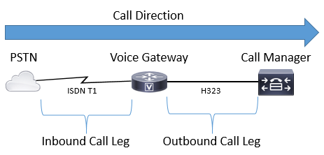
Image 1 shows a call from the PSTN to CUCM routing through a Cisco Voice Gateway and the respective
inbound and outbound call leg information.
Image 1 - Inbound and Outbound Call Legs Illustrated
A successful call through a Cisco Gateway ALWAYS (see note) matches an inbound or outbound dial-peer
to route properly. Inbound and outbound dial-peers are similar to the call-legs mentioned earlier. In Image 1,
the call arrives from the PSTN at the Cisco Gateway and needs to match an inbound dial-peer. Then the
gateway utilizes an outbound dial-peer to route the call to the next call agent. It is important to remember
that these terms are defined from the perspective of the Cisco Gateway.
By matching a dial-peer for each side of the call, an administrator has the power to control many aspects of
each specific call leg. Examples of these include voice codecs, DTMF preferences, digit manipulation,
where the call is to be routed, and many other settings. Dial-peers can be configured with both inbound and
outbound match statements so matching the same dial-peer for both the in-leg and out-leg is possible if a
valid inbound and outbound matching configuration is applied to that specific dial-peer.
Note: The exception to this rule is with MGCP and SCCP voice-ports. These signaling protocols do
not follow normal dial-peer matching mechanism during call routing. See the SCCP and MGCP
section for further details.
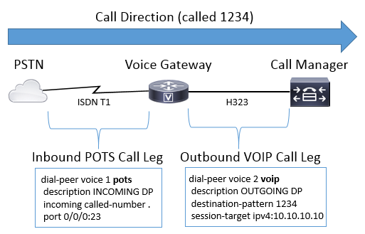
Image 2 illustrates the same inbound and outbound call legs as Image 1 but with the respective dial-peers for
a call from the PSTN to CUCM routing through an Cisco Voice Gateway.

Page 10
Image 2 - Inbound and Outbound dial-peers Illustrated
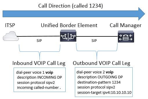
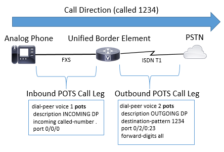
Cisco Voice Gateways can interwork many different types of voice calls and protocols including IP to IP,
POTS to POTS and IP to POTS or vice versa.
Image 3 illustrates a VoIP to VoIP call through Cisco Unified Border Element (CUBE).
Page 11
Image 3 - Inbound and Outbound dial-peers for a Voip to VoIP call
Image 4 displays a POTS to POTS call through a Cisco Gateway.
Page 12
Image 4 - Inbound and Outbound dial-peers for a POTS to POTS call
Voice Dial-Peer Types
POTS
Plain Old Telephony Service dial-peers are matched for analog connections such as Analog FXS,
FXO, ISDN T1 / E1s, E1 R2, and Ear and Mouth (E&M) connections.
These send or receive a call to / from a physical voice-port on the gateway.
VOIP
Voice Over IP dial-peers are used to mainly control H323 and SIP connections to and from the
gateway.
These dial-peers send and receive signaling from both IPv4 and IPv6 addresses as well as Fully
Qualified Domain Names (FQDN) using Domain Name System (DNS).
VoIP dial-peers can also be used for Voice over Frame Relay (VoFR), Voice over ATM
(VoATM), Voice over High-Level Data Link Control (VoHDLC) and Registration, Admission,
and Status (RAS) signaling and session targets for these dial-peers can also include settlements and
ENUM values.
Note: Some of these types of configurations are older technologies not seen in newer networks and
with Cisco IOS XE some are no longer supported. As a result they are not be covered in this
document.
Page 13
MMOIP
Multimedia Mail Over IP dial-peers are utilized to send emails to exchange servers.
These are mostly utilized for t37 on-ramp / off-ramp faxing. These dial-peer types are not within
the scope of this document.
Note: The maximum number of dial-peers that can be configured on a Cisco gateway depends on the
available memory (DRAM). Each dial-peer consumes approximately 6KB of memory, so ensure that
the gateway has at least 20% of the total memory reserved for other CPU processes. A large number
of configured dial-peers can add to the delay to route a call. This can be significant as the Cisco voice
application looks through dial-peers from the top down, similar to an Access Control List (ACL). This
is usually not a problem on newer Cisco Gateways.
Sample Error:
May 26 12:59:46.406: %DIALPEER_DB-3-ADDPEER_MEM_THRESHOLD: Addition of dial-peers limited by available m
Inbound Dial-Peer Matching
When a Cisco Gateway receives a call setup request, the gateway begins searching for an applicable
incoming dial-peer for this call. This is not a digit-by-digit analysis; rather, the full message is utilized to
determine which inbound dial-peer is selected. The order of items in the message checked is
largely dependent on the protocol for the call as indicated by the preference lists defined in Table 1, Table 2,
and Table 3. A dial-peer only needs to satisfy one of the conditions for matching. It is not necessary for all
the attributes to be configured in the dial-peer or that every attribute match the call setup information. All
dial-peers are searched based on the first match criteria. The gateway moves on to the next criteria only if no
match is found.
Table 1. Inbound SIP Dial-Peer Selection Preference
Preference Match Criteria
Dial-peer Commands
1
URI
incoming uri via <uri-tag>
2
URI
incoming uri request <uri-tag>
3
URI
incoming uri to <uri-tag>
4
URI
incoming uri from <uri-tag>
incoming called-number <number-string>
5
Called Number

Page 14
incoming called e164-pattern-map <pattern-map-number>
6
Calling Number
incoming calling e164-pattern-map <pattern-map-number>
answer-address <number-string>
7
Destination-pattern (ANI) destination-pattern <number-string>
8
Carrier-ID
carrier-id source <string>
Note: Eligible inbound dial-peers can be filtered by VRF, or Tenant. if the applicable feature is
configured. For more information, see Virtual Routing and Forwarding (VRF) and Dial-Peer
Hunting and Voice Class Tenants sections.
Table 2. Inbound H323 Dial-Peer Selection Preference

Page 15
Preference Match Criteria
Dial-peer Commands
1
URI
incoming uri called <uri-tag>
incoming uri calling <uri-tag>
2
Called Number
incoming called-number <number-string>
incoming called e164-pattern-map <pattern-map-number>
3
Calling Number
incoming calling e164-pattern-map <pattern-map-number>
answer-address <number-string>
4
Destination-pattern (ANI) destination-pattern <number-string>
5
Carrier-ID
carrier-id source <string>
Table 3. Inbound Enbloc POTS Dial-Peer Selection Preference
Preference Match Criteria
Dial-peer Commands
1
Called Number
incoming called-number <number-string>
2
Calling Number
answer-address <number-string>
3
Destination-pattern (ANI) destination-pattern <number-string>
4
Voice-port
port <voice-port-number>
When No Matches Exist / Default Dial-Peer 0 peer_tag=0, pid:0
When there are no eligible matches for an inbound dial-peer for either POTS or VoIP calls, the gateway
allocates dial-peer 0. This is not ideal as dial-peer 0 has limited capabilities and can cause issues with calls.
The outlier to this is SCCP and MGCP protocols which do not use dial-peers for routing calls. See the
MGCP and SCCP section for further details.
dial-peer 0 capabilities
No dtmf-relay mechanisms.
•
Advertised all voice codecs for VoIP calls.
•
Page 16
Fax-rate voice.
•
Voice Activity Detection (VAD) is enabled.
•
No RSVP Support.
•
No IVR Application Support for POTS calls.
•
Direct-inward-dial is enabled.
•
Does not support VRF.
•
Outbound Dial-Peer Matching
Outbound dial-peers are utilized to route POTS or VoIP calls from the gateway to the next call agent. Like
inbound dial-peer matching, there is a list of items the gateway can use to match dial-peers based on the
preference order for the specific protocol. However, unlike inbound dial-peers, if there is no
eligible outbound dial-peer to route the call, then the call fails. Like inbound dial-peer matching, all dial-
peers are searched based on the first match criteria. The gateway moves on to the next criteria only if no
match is found.
Table 4. Outbound SIP Dial-Peer Selection Preference
Preference Match Criteria
Dial-peer Commands
1
Dial-Peer Group Dial-Peer
destination dpg <dpg-tag>
(DPG configured on inbound dial-peer)
2
Dial-Peer Provision Policy
URI
destination uri-from <uri-tag>
destination uri-to <uri-tag>
destination uri-via <uri-tag>
destination uri-diversion <uri-tag>
destination uri-referred-by <uri-tag>
(DPP configured on inbound dial-peer)
3
ILS Route String
destination route-string <route-string-tag>
4
URI and Carrier-ID
destination uri <uri-tag> AND carrier-id target <string>
5
Called Number and Carrier-
ID
destination-pattern <number-string> AND carrier-id target
<string>
6
URI
destination uri <uri-tag>
7
Called Number
destination-pattern <DNIS-number>
destination e164-pattern-map <pattern-map-number>
dnis-map <dnis-map-number>
Page 17
8
Calling Number
destination calling e164-pattern-map <pattern-map-number>
Note: When both incoming and outgoing dial peers are configured with calling e164-pattern-map, it
is essential to apply a dial-peer provision policy to the incoming dial peer to avoid call failures.
Table 5. Outbound H323 Dial-peer Selection Preference
Preference Match Criteria
Dial-peer Commands
1
Dial-Peer Group Dial-Peer
destination dpg <dpg-tag>
(configured on inbound dial-peer)
2
URI and Carrier-ID
destination uri <uri-tag> AND carrier-id target <string>
3
Called Number and Carrier-
ID
destination-pattern <number-string> AND carrier-id target
<string>
4
URI
destination uri <uri-tag>
5
Called Number
destination-pattern <number-string>
destination e164-pattern-map <pattern-map-number>
dnis-map <dnis-map-number>
6
Calling Number
destination calling e164-pattern-map <pattern-map-number>
Table 6. Outbound POTS Dial-peer Selection Preference
Preference Match Criteria
Dial-peer Comamnds*
1
Dial-Peer Group Dial-Peer
destination dpg <dpg-tag>(configured on inbound dial-peer)
2
URI and Carrier-ID
destination uri <uri-tag> AND carrier-id target <string>
3
Called Number and Carrier-
ID
destination-pattern <number-string> AND carrier-id target
<string>
4
URI
destination uri <uri-tag>

Page 18
5
Called Number
destination-pattern <DNIS-number>dnis-map <map-number>
Note: The Number String Dial-Peer Hunting and URI Dial-Peer Hunting section go into how the
gateway evaluates a list of potential commands for each match criteria row before moving to the next
match criteria. For example, it evaluates all potential destination-pattern matches and destination
e164-pattern-map matching commands before it examines the calling number commands.
Number String Dial-Peer Hunting
Number String Preference:
Much like URIs have a specific order of operations for evaluating matches, there is also a set of rules used
when evaluating a numeric digit-string. The default dial-peer hunt scheme for a Cisco gateway is set to 0.
This means the gateway searches for a pattern with the longest match (most specific). If there are two dial-
peers with the same match length, the gateway looks at the explicitly defined dial-peer preference. Lastly, if
both of those are the same, it chooses one in a random order.
There are other dial-peer hunt schemes available for configuration; however, most deployment keep the
default of 0.
Tip: If dial-peers are being matched outside the default order, an administrator can examine the
running configuration for a non-default dial-peer hunt scheme.
Gateway(config)# dial-peer hunt ?
<0-7> Dial-peer hunting choices, listed in hunting order within each choice:
0 - Longest match in phone number, explicit preference, random selection.
1 - Longest match in phone number, explicit preference, least recent use.
2 - Explicit preference, longest match in phone number, random selection.
3 - Explicit preference, longest match in phone number, least recent use.
4 - Least recent use, longest match in phone number, explicit preference.
5 - Least recent use, explicit preference, longest match in phone number.
6 - Random selection.
7 - Least recent use.
The longest match number string dial-peer algorithm finds the dial-peer with the most numbers in a
sequence that exactly match a sequence of numbers in a number string. This concept is clarified in the
subsequent scenario.
Scenario: Eligible dial-peers have been configured with these possible matches, and the gateway is
evaluating a digit-string of 2001. Dial-peer 1 can match any number 2000 through 2999 while dial-peer 2
can match 2000 through 2009. Dial-Peer 2 would be matched for this call as it is the longest match (most
specific) for the digit string 2001 when the default dial-peer hunting mechanisms is employed (dial-peer
hunt 0). In other words, the sequence of numbers 200 is the largest sequence that exactly matches a
sequence of number in the number string 2001.
!


Page 19
dial-peer voice 1 voip
destination-pattern 2...
!
dial-peer voice 2 voip
destination-pattern 200.
!
Preference is defined as the administrator defined weight for each dial-peer. Administrators can configure a
preference so the call always uses a specific dial-peer before others. By default, all dial-peers are preference
0. A dial-peer with preference 0 is matched before another dial-peer with preference 1 through 10. Most
administrators setup multiple dial-peers to send a call to a specific CUCM subscriber with a backup
subscriber or another call agent being configured using another dial-peer with a lower preference (which is
configured with a higher number).
Scenario: Two dial-peers are configured with the same match length for the digit string of 2001. The
administrator defines an explicit preference. The gateway evaluates both dial-peers the same since their
match length is the same. However, the administrator sets dial-peer 1 with a higher preference so that dial-
peer is chosen as the first dial-peer used in routing the call. Dial-Peer 2 would remain as a secondary option
can a failure occur on the first dial-peer.
!
dial-peer voice 1 voip
destination-pattern 2...
preference 1
!
dial-peer voice 2 voip
destination-pattern 2...
preference 2
!
A Cisco gateway only attempts to route a call via one eligible outbound dial-peer at a time. If a failure
condition is observed on the first selected dial-peer, then the gateway attempts to route the call out the next
eligible dial-peer. This continues until the call either succeeds or fails because there are no more eligible
dial-peers left to try. A common symptom of dial-peer hunting and failure is a noticeable delay in ringback
while making calls. Debugs are usually needed to verify exactly why the call is failing on a given dial-
peer. The command huntstop can be employed on a dial-peer if an administrator does not want a gateway to
look for another dial-peer when a failure condition is observed.
Scenario: Two dial-peers are configured with the same match length for the digit string of 2001. The
administrator has defined an explicit preference and does not want to match dial-peer 2 for this particular
call. Since there are two dial-peers with the same match-length, the preference is used to determine the dial-
peer. Dial-Peer 1 has the lowest configured preference number, so it is used to route the call. If a failure
condition occurs on the outbound call leg using dial-peer 1, then the gateway immediately stops dial-peer
hunting since the huntstop command is configured. In this scenario, dial-peer 2 is never utilized for
outbound routing.
!
dial-peer voice 1 voip
destination-pattern 2...
preference 1
huntstop
Page 20
!
dial-peer voice 2 voip
destination-pattern 2...
preference 2
!
Note: huntstop and preference commands can also be used in conjunction with URI matching
statements as they are general dial-peer configuration commands. Furthermore, voice class server-
group configurations can utilize huntstop commands in 17.4.1a. Refer to the section Destination
Server-Groups for more details on this.
URI Dial-Peer Hunting
The gateway looks at each match criteria and exhausts it before it moves to the next match criteria. An
example of this would be on an inbound SIP call. Based on Table 1. Inbound SIP Dial-Peer Selection
Preference, the first thing the Cisco gateway checks is the URI and evaluates all potential URI commands to
find one that fits. If there is no match, or none are configured, then the gateway moves to the next matching
item and performs an evaluation on that criteria. This process repeats until the call either routes based on a
match or the gateway runs out of match criteria to check.
When an inbound or outbound dial-peer is configured with a URI command, the gateway examines the URI
that was received in multiple headers for a potential match. The match preference is based on the most
specific match and the exact preference goes Full URI match, Host Portion, User Portion, or telephone URI.
Knowing the order of operations for URI matching can greatly aid in dial-peer matching with SIP and
CUBE deployments.
This preference order can be manipulated using the command voice class uri sip preference to specify the
user-id as the first option instead of host.
URI Preference:
The Host portion of the URI. Examples: (@<ip_address> or @example.com)
1.
The User portion of the URI. Examples: (sip:8675309 or sip:user)
2.
The tele-uri. Example: (tel:18005532447)
3.
Exact match for the full URI. Examples: (user@host.domain.name, user@<ip_address>,
8675309@example.com, 8675309@example.com)
4.
Supporting Document: Cisco Unified Border Element Configuration Guide - Cisco IOS XE 17.6 Onwards
Scenario: An administrator has configured this dial-peers and sends a call to the gateway. The From header
in the received Invite is From: sip:testuser@192.0.2.1. The gateway can potentially match two different
dial-peers based on this header. Dial-Peer 1 based on the user portion and dial-peer 2 based on the host
portion. However, since a host match is a preference over a user match, dial-peer 2 is used for the inbound
dial-peer in the call.
!
voice class uri URI1 sip
user-id testuser
!
voice class uri URI2 sip
host ipv4:192.0.2.1
!

Page 21
dial-peer voice 1 voip
sess protocol sipv2
incoming uri FROM URI1
!
dial-peer voice 2 voip
sess protocol sipv2
incoming uri FROM URI2
!
Voice Class URI
URI matching for inbound and outbound dial-peers allows an administrator the ability and flexibility to
perform matches on more than a phone number string for VoIP protocols supporting URIs in their
messaging. Prior to Cisco IOS 15.4(1)T and Cisco IOS-XE 3.11S, a request URI had to contain an
alphanumeric user@host else a Cisco gateway would reject the call with a 4xx message. Now a URI can
contain just the host portion, and the gateway routes the call based on just the host provided. For example,
sip:cisco.com.
Additionally, prior to Cisco IOS 15.4(1)T and Cisco IOS-XE 3.11S voice-class URI user-ids could only be
numeric e.164 values (sip:1234@example.com). This was changed so administrators can configure
alphanumeric user-ids on CUBE (sip:user@example.com).
The host or user portion of a voice class uri can contain regular expressions (regex) patterns which greatly
expands the possible values that can be matched.
Gateway(config-voice-uri-class)# user-id .)
% unmatched ()user-id pattern can be of format ^([][0-9A-Za-z|/()+^$&?#--.])$
Gateway(config-voice-uri-class)# host .)
% unmatched ()host pattern can be of format ^([][0-9A-Za-z|@/()+^$&?#--.])$
Gateway(config-voice-uri-class)# pattern .)
% unmatched ()pattern pattern can be of format ^([][0-9A-Za-z|@;:=%!~/()+^$&?#--.])$
Example: Voice Class URIs
!
voice class uri HOST sip
host example.com
host dns:cisco.example.com
host ipv4:10.50.244.2
host ipv6:[2001:4860:4860::8888]
!
voice class uri USER sip
user-id username
!
voice class uri PATTERN sip
pattern 8675309
!
voice class uri HostRegex sip
Page 22
host (.)example.com
!
voice class uri ipRegex sip
host 172.18.110.20[567]
!
voice class uri PatternRegex sip
pattern 555(.)
!
voice class uri ipRegex sip
pattern (172.18.110.10[134]|10.10.10.10)
! One Line that matches 172.18.110.101, 172.18.110.103, 172.18.110.104 OR 10.10.10.10
!
voice class uri UserRegex sip
user-id test(.*)
!
Only 10 hosts, 1 pattern, or 1 user-id can be configured per voice class uri, as this example demonstrates. If
more items need to be matched, it is recommended to use Regex.
Gateway(config)# voice class uri TEST sip
Gateway(config-voice-uri-class)#host ipv4:10.1.1.1
Gateway(config-voice-uri-class)#host ipv4:10.2.2.2
Gateway(config-voice-uri-class)#host ipv4:10.3.3.3
Gateway(config-voice-uri-class)#host ipv4:10.4.4.4
Gateway(config-voice-uri-class)#host ipv4:10.5.5.5
Gateway(config-voice-uri-class)#host ipv4:10.6.6.6
Gateway(config-voice-uri-class)#host ipv4:10.7.7.7
Gateway(config-voice-uri-class)#host ipv4:10.8.8.8
Gateway(config-voice-uri-class)#host ipv4:10.9.9.9
Gateway(config-voice-uri-class)#host ipv4:10.10.10.10
Gateway(config-voice-uri-class)#host ipv4:10.11.11.11
Error:Maximum of 10 hosts can only be configured.
Gateway(config)# voice class uri TEST2 sip
Gateway(config-voice-uri-class)#host dns:1.com
Gateway(config-voice-uri-class)#host dns:2.com
Gateway(config-voice-uri-class)#host dns:3.com
Gateway(config-voice-uri-class)#host dns:4.com
Gateway(config-voice-uri-class)#host dns:5.com
Gateway(config-voice-uri-class)#host dns:6.com
Gateway(config-voice-uri-class)#host dns:7.com
Gateway(config-voice-uri-class)#host dns:8.com
Gateway(config-voice-uri-class)#host dns:9.com
Gateway(config-voice-uri-class)#host dns:10.com
Gateway(config-voice-uri-class)#host dns:11.com
Error:Maximum of 10 hosts can only be configured.
Gateway(config)# voice class uri TEST3 sip
Gateway(config-voice-uri-class)#user-id 8675309
Gateway(config-voice-uri-class)#user-id 123456789
Gateway(config-voice-uri-class)#do sh run | s TEST3
voice class uri TEST3 sip
user-id 123456789
Gateway(config)# voice class uri TEST4 sip
Gateway(config-voice-uri-class)#pattern 8675309
Gateway(config-voice-uri-class)#pattern 123456789
Page 23
Gateway(config-voice-uri-class)#do sh run | s TEST4
voice class uri TEST4 sip
pattern 123456789
Inbound URI Dial-Peer Matching
This feature was added in Cisco IOS 15.1(2)T and Cisco IOS-XE 3.8S and utilizes a voice class uri
configured and applied to an inbound dial-peer. Incoming URI has been adopted by many people over the
traditional incoming called-number statement for SIP calls as it the first match criteria checked when
selecting inbound dial-peers. The command also allows administrators the ability to better match calls that
come from a particular call agent or user.
Full Documentation: Cisco Unified Border Element Configuration Guide - Cisco IOS XE 17.6 Onwards
Common Use Cases
An inbound dial-peer matching on the host portion of the URI to answer OPTIONS ping requests
from CUCM.
1.
An inbound dial-peer matching on the host portion of the URI to control inbound calls from an
Internet Telephony Service Provider (ITSP)
2.
An inbound dial-peer matching on the user-id portion of the URi for call treatment from certain users
or numbers.
3.
Configuration Example
This example output matches dial-peer 777 for any SIP request sourcing from the two HOST IPs defined in
the voice class URI. The header watched is defined as the From header on the dial-peer; however, an
administrator can define many others including VIA, TO, and REQUEST (Request URI). If the CUCM
sends an OPTIONS ping to the CUBE now matches dial-peer 777 and source my 200 OK reply to the
OPTIONS from the specified interface. If CUCM sends an Invite to the CUBE matches dial-peer 777 as the
inbound dial-peer.
!
voice class uri CUCM sip
host ipv4:10.50.244.2
host ipv4:10.50.244.20
!
dial-peer voice 777 voip
description INCOMING URI
session protocol sipv2
incoming uri from CUCM
voice-class sip bind control source-interface Loopback777
voice-class sip bind media source-interface Loopback777
!
Outbound URI Dial-Peer Matching
Cisco IOS gateways can match an outbound dial-peer using a URI by applying a voice class uri to an
outbound dial-peer and adding call-route url to global configuration. When this is present, the CUBE can try
to route calls based on the Request URI. This feature was added in Cisco IOS 12.3(4)T and is present in all
Page 24
Cisco IOS XE versions. It can be noted that by default the outgoing SIP Request-URI and To header URI
have the session target of the outbound-dial-peer. This can be disabled by using the command requri-
passing which allows the gateway to pass the in-leg URI host portion to the out-leg instead of replacing the
URI host portion with the session-target. The command requri-passing was added in 15.4(1)T and Cisco
IOS XE 3.11S.
Configuration Example
voice service voip
sip
call-route url
requri-passing
!
voice class uri CUCM sip
host dns:.*.com
!
dial-peer voice 777 voip
description OUTGOING URI
session protocol sipv2
destination uri CUCM
session target sip-uri
!
Source: Cisco Unified Border Element Configuration Guide - Cisco IOS XE 17.6 Onwards
In addition to voice class URI, administrators can use a dial-peer provision-policy (DPP) to match an in-leg
URI for an outbound dial-peer match. This feature was added in Cisco IOS 15.4(2)T and Cisco IOS XE
3.12S. A dial-peer provision-policy requires defining a primary match attribute with a secondary match
attribute being optional. The provision-policy is applied to an inbound dial-peer, and when that dial-peer is
selected for use on an inbound call-leg, the policy is invoked. The result is an outbound dial-peer selection
based on the attribute from the dial-peer provision-policy.
The outbound match can be a single header or multiple headers which all must be true in order to match the
dial-peer.
In the example, there is a voice class uri for the From and To headers. For an OR match, a dial-peer
provision-policy is configured which contains two preferences. The From header is the first preference, and
the To header is the backup preference. Dial-Peer 1234 is built to apply the provision policy for inbound
matching. Then built dial-peer 11111 and 22222 which apply the destination uri-from and destination uri-to
commands respectively. These commands point back to their voice class URI. For the call, you can receive
the Invite, match dial-peer 1234 and check the provision-policy. The device can then try to route on the
From header first which as an applicable match on dial-peer 11111. If this fails, you can also try to route on
the to header with 22222.
The example also details how to achieve an And match with dial-peer provision-policies. Assuming the
same Invite is received, you can define two headers under one preference and apply this to the inbound dial-
peer.
Now when the invite is received, it can check for eligible outbound dial-peers which satisfy both matching
criteria defined in the provision-policy. So in this example, your outbound dial-peer needs to be defined with
both the TO and FROM header in order to be matched. If either are not a valid match, this dial-peer 12345 is
not used.
Page 25
Note: Although we are routing the call on the From header the Invite that leaves the gateway still
has the original Request URI. We simply use the Dial-peer provision-policy to match an outbound
dial-peer not change the request URI.
Configuration Example
<#root>
Received INVITE
Received:
INVITE sip:8675309@172.18.110.58:5060 SIP/2.0
From: sipp sip:sipp@172.18.110.65;tag=1
To: sut sip:cube@172.18.110.58:5060
Common Configurations
!

Page 26
voice class uri FROM sip
user-id sipp
!
voice class uri TO sip
user-id cube
!
OR Match
!
voice class dial-peer provision-policy 1
description match from header. If false, try to header
preference 1 from
preference 2 to
!
dial-peer voice 1234 voip
session protocol sipv2
destination provision-policy 1
incoming called-number .
!
dial-peer voice 11111 voip
destination uri-from FROM
session protocol sipv2
session target ipv4:172.18.110.48
!
dial-peer voice 22222 voip
destination uri-to TO
session protocol sipv2
session target ipv4:172.18.110.48
!
AND Match
!
voice class dial-peer provision-policy 2
description match from AND to headers
preference 1 from to
!
dial-peer voice 1234 voip
session protocol sipv2
destination provision-policy 2
incoming called-number .
!
dial-peer voice 12345 voip
destination uri-from FROM
destination uri-to TO
session protocol sipv2
session target ipv4:172.18.110.48
!
Source: Cisco Unified Border Element Configuration Guide Through Cisco IOS XE 17.5
session target sip-uri
Prior to Cisco IOS 15.4(1)T and Cisco IOS XE 3.11S if the host portion of a URI was different, but the user
was the same, this would require two separate outbound dial-peers.
Page 27
After this release, an administrator can configure one dial-peer to service multiple hosts for the same user.
For example, testuser@example.com and testuser@example.net under the same dial-peer. Using session
target sip-uri triggers DNS resolution of the domain of incoming Invite Req-URI and dynamically determine
the session target IP.
Example Configuration:
The gateway recieves two SIP Invites with these headers Invite sip:testuser@example.com:5060 SIP/2.0
Invite sip:testuser@example.net:5060 SIP/2.0 The gateway matches the incoming SIP request of
testuser@example.com and testuser@example.net on dial-peer 1 because of the incoming URI command
and the user-id definition both match testuser. The command voice-class sip call-route url is present means
you evaluate outbound dial-peers based on the request URI of this inbound Invite. You match dial-peer 2
because of the same reasons you matched dial-peer 1, the user-id of testuser. The session target of this dial-
peer is the original sip-uri as defined by session target sip-uri, which was a FQDN. After a DNS resolution
has taken place, and change example.com and example.net into an IP for layer 3 routing you send a message
out of the gateway.
!
ip host example.com 192.0.2.10
ip host example.net 192.0.2.10
!
voice class uri TEST-IN sip
user-id testuser
!
dial-peer voice 1 voip
description INCOMING dial-peer
incoming uri request TEST
session protocol sipv2
voice-class sip call-route url
!
dial-peer voice 2 voip
description OUTBOUND dial-peer
destination uri TEST
session protocol sipv2
session target sip-uri
!
Verification:
show voice class uri <uri-name>
show voice class dial-peer provision-policy <number>
debug voip uri
Dial-Peer Wildcards
An administrator can utilize dial-peer wildcards when defining inbound and outbound matching mechanisms
that involve a number string. These include destination-pattern, incoming called-number, e164-pattern-
maps, and answer-address as well as the prefix command. Dial-peer wildcards are regular expressions
Page 28
(regex) available for configuration which allow greater flexibility over the matching of dial-peers.
Wildcard Table
Character Definition
Examples
*
On a dial-peer this is a literal value of * (star) on the keypad.
12345*
On a dial-peer this is a literal value of # (pound) on the keypad.
8675309#
,
Inserts a 1 second pause between digits.A comma can also be used
within brackets [ ] to break up a continuous range.
9,,,,,55591[1-3,5-
9]8675309
.
Regex character for matching any value 0-9, A-F and *, #, +
Up to 15 dot characters can be defined per dial-peer although the CLI
lets an administrator configure as many as they see fit.
If more than 15 dots are require please use T.
2....
91[2-9]..[2-9]......
%
Regex for preceding digit occurring zero or more times.
When used at the beginning of a string it means a literal + used in E164
numbers.
When used anywhere else in the string it is a regex value for the
preceding digit occurring one or more times.
+19191112222
?
Regex for the preceding digit occurring zero or one time.
(206)?5015111
(0)?(1)?(1)?21933...
^
Regex character to indicate the start of the string when used outside of
brackets
When used inside brackets it is treated as an exclude or a DO NO
MATCH Statement
This is no longer required in later versions as the gateway automatically
assume a ^ when processing a regex string without a ^.
^8675309
91[^135]555
$
Regex character to indicate the end of a string.
8675309$
Escape character to mean a literal value
Page 29
[ ]
Brackets define a range of characters for a single position.
Commas must be used to break up continuous strings.
[1-5]0000
[2,5-8]0000
( )
Parenthesis define a group of characters in a set.
9(258)7777
T
A variable length match of up to 32 digits.
The router waits on the inter-digit timeout to occur before routing the
call.
The default value for the interdigit timeout is 10 seconds and is
modifiable via timeouts inter-digit on a voice-port.
Administrators can terminate the inter-digit timeout using # on the
keypad. This is modifiable via the command dial-peer terminator
configured globally.
T also references the T302 timer.
9011T
Used in brackets to define the range.
[5-9]1234
Output from Gateway that displays the possible regular expression inputs.
Gateway(config-dial-peer)# destination-pattern asdfqw4r3~2
Incorrect format for E.164 Number
regular expression must be of the form ^[][^0-9,A-F#*.?+%()-]*T?($)?$
Dial-Peer States
Dial-peers can be in one of two Operational states.
Up
1.
Down
2.
For a dial-peer to be in a valid operational state, and eligible for use with call routing, it needs to be in the
UP state. For outbound VOIP dial-peers, this means there can be a valid outbound matching mechanisms as
well as a valid session target to route the call towards. For outbound POTS dial-peers, a valid outbound
matching mechanism as well as a valid voice-port can be configured. With inbound dial-peers only, a valid
inbound matching mechanisms must be configured.
The busyout state is seen when a dial-peer is configured with a keepalive mechanisms and the remote target
has failed the parameters of that keepalive mechanism. The gateway then moves the dial-peer into a busyout
state so it is no longer used for call routing decisions, and when the keepalive mechanism is fulfilled again,
the gateway puts the dial-peer back into an up state. If a dial-peer is selected as an outbound dial-peer, and
this dial-peer is in a busyout state, the gateway fails the call with a cause code 188.
Page 30
Along with operational states there are Administrative states.
Up
1.
Down
2.
An administrator can disable a dial-peer without removing it from the configuration by entering the
shutdown command on the dial-peer. To re-enable the dial-per enter no shutdown.
Note: A dial-peer with a voice-port that is down, shutdown, or not operational, remains in
operational state of Up however the Out State shows as Down.
Verification
Gateway# show dial-peer voice summary
dial-peer hunt 0
AD PRE PASS OUT
TAG TYPE MIN OPER PREFIX DEST-PATTERN FER THRU SESS-TARGET STAT PORT KEEPALIVE
1 voip up up 0 syst
777 voip up up 9... 0 syst ipv4:10.50.244.2

Page 31
555 voip up down 555 0 syst
888 pots up up 888 0 up 0/2/0
999 pots up up 999 0 down 0/2/0
123 voip up up 123 0 syst ipv4:10.10.10.10 busyout
Virtual Routing and Forwarding (VRF) and Dial-Peer Hunting
Inbound Dial-Peer Matching with VRF
Starting with Cisco IOS 15.6(3)M and Cisco IOS-XE 16.3.1, Cisco gateways can match inbound dial-peers
using VRF IDs. To take advantage of this, an administrator must bind the inbound dial-peer to an interface
which in turn binds the dial-peer to the VRF ID on the specified interface. After the bind is complete,
inbound calls are filtered by the Cisco Gateway to only only include eligible inbound dial-peers that match
the VRF ID of the interface the packet was received on. From here the inbound dial-peer is matched based
on regular dial-peer matching order of operations.
Prior to these Cisco IOS / Cisci IOS-XE releases, the Cisco Gateway would make an inbound selection
based on regular inbound dial-peer matching without any filtering. This means a VRF1 call could be
matched by a VRF2 dial-peer. Additionally, since only one VRF was supported by H323 and SIP prior to
these releases other issues arise when attempting to use multi-VRF features. The use of a single VRF for
voice applications was known as VRF-Aware configuration.
Full VRF-Aware Documentation: VRF-Aware H.323 and SIP for Voice Gateways
Full Multi-VRF Documentation: Cisco Unified Border Element Configuration Guide - Cisco IOS XE 17.6
Onwards
Outbound Dial-Peer Matching with VRF
Cisco Gateways have the ability to bridge calls across VRFs without the need for route leaks to be
configured. This means an inbound call on VRF1 can be routed outbound on a dial-peer for VRF2 if the
normal outbound dial-peer matching selection is satisfied. Dial-peer groups can be employed to force the
Cisco gateway to keep the call within the same VRF.
VRF and Dial-Peer Group Configuration Example
This configuration example has VRF1 and VRF2 with two overlapping IP Ranges and two overlapping
phone number ranges.
Utilize VRF binding to ensure the correct inbound dial-peer is matched, and Dial-peer Groups to ensure the
correct VRF bound outbound dial-peer is matched. If a SIP packet for a call to 8675309 arrives on
gig0/0/1.2, then the gateway filters out all available inbound dial-peers based on the VRF2 ID. This means
you cannot match dial-peer 10. Now when you check the digit-string, you can match dial-peer 20. Dial-peer
20 has a dial-peer group which tells the gateway the only outbound dial-peer that can be matched is also
dial-peer 20. This dial-peer group allows you to avoid matching dial-peer 10 and crossing a call coming
from VRF1 into VRF2. From there the call can proceed as normal.
!
interface GigabitEthernet0/0/1.1
description VRF1
Page 32
encapsulation dot1Q 10
ip vrf forwarding VRF1
ip address 10.10.10.10 255.255.255.0
!
interface GigabitEthernet0/0/1.2
description VRF2
encapsulation dot1Q 20
ip vrf forwarding VRF2
ip address 10.10.10.10 255.255.255.0
!
voice service voip
no ip address trusted authenticate
media-address voice-vrf VRF1
media-address voice-vrf VRF2
allow-connections sip to sip
sip
!
voice class dpg 10
description INBOUND VRF1 to OUTBOUND VRF1
dial-peer 10 preference 1
!
voice class dpg 20
description INBOUND VRF2 to OUTBOUND VRF2
dial-peer 20 preference 1
!
dial-peer voice 10 voip
description VRF1
destination-pattern 8675309
session protocol sipv2
session target ipv4:10.10.10.20
destination dpg 10
incoming called-number 8675309
voice-class sip bind control source-interface GigabitEthernet0/0/1.1
voice-class sip bind media source-interface GigabitEthernet0/0/1.1
!
dial-peer voice 20 voip
description VRF2
destination-pattern 8675309
session protocol sipv2
session target ipv4:10.10.10.20
destination dpg 20
incoming called-number 8675309
voice-class sip bind control source-interface GigabitEthernet0/0/1.2
voice-class sip bind media source-interface GigabitEthernet0/0/1.2
!
Verification
Gateway# show vrf brief | i VRF
VRF1 1:1 ipv4 Gi0/0/1.1
VRF2 2:2 ipv4 Gi0/0/1.2
Gateway# show dial-peer voice summary
TAG TYPE MIN OPER PREFIX DEST-PATTERN FER THRU SESS-TARGET STAT PORT KEEPALIVE VR
10 voip up up 8675309 0 syst ipv4:10.10.10.20 VR
20 voip up up 8675309 0 syst ipv4:10.10.10.20 VR
Page 33
Gateway# show voice class dpg 10
Voice class dpg: 10 AdminStatus: Up
Description: INBOUND to OUTBOUND VRF1
Total dial-peer entries: 1
Peer Tag Pref
10 1
Gateway# show voice class dpg 20
Voice class dpg: 20 AdminStatus: Up
Description: INBOUND to OUTBOUND VRF2
Total dial-peer entries: 1
Peer Tag Pref
20 1
Advanced Call Routing Techniques
Over the years as business needs grow, the company expands and requires more DIDs and enterprise
administrators can find that the basic dial-peers do not meet scale well. There can be on-off situations that
need to be addressed, or perhaps there are just too many dial-peers in general. Having thousands of dial-
peers does not make administration and troubleshooting easy. Having a dial-peer for each specific CUCM
server or call agent starts to compound the problem of too many dial-peers because now an administrator
needs to configure a dial-peer for for each digit-string. If there is have more than one SIP provider
connecting to a gateway, or a few different people using the same CUBE, this makes isolating a specific
tenant very tough.
Cisco has taken this feedback and created a set of items that can address these issues and more. Dial-peer
Groups, Voice Class tenants, destination server-groups, e164-pattern-maps and POTS trunk groups allow for
an administrator to solve all of the problems listed and many more not listed.
Dial-Peer Groups
Dial-peer groups were added in Cisco IOS 15.4(1)T and Cisco IOS-XE 3.11S and POTS dial-peers were
added as an option in Cisco IOS 15.5(1)T and Cisco IOS-XE 3.14S. A dial-peer group allows administrators
to specify an exact dial-peer for outbound routing based on the inbound dial-peer matched. Once an inbound
dial-peer with a dial-peer group configured is matched, the call uses the dial-peer defined in the dial-peer
group even if the destination-pattern does not match. The only prerequisite is the outbound dial-peer must be
Up so an outbound matching method must be configured, however, this is not actually used to route the call.
The best way to describe dial-peer groups is to liken them to the concept of static routes in a routing table.
These are static inbound to outbound routing decisions that take away some of guesswork for the gateway
because they are telling it exactly how to route the call.
Full Documentation: Cisco Unified Border Element Configuration Guide - Cisco IOS XE 17.6 Onwards
Page 34
Configuration Example
With this example, the called number is 8675309. This matches dial-peer 1234 based on the incoming
called-number statement. This dial-peer is configured with a dial-peer group that states the call can now
route out dial-peers 2, then 3, and finally 1 if dial-peer 2 fails. This the gateway so now try to route the call
out dial-peer 2 as it has been explicitly told via the dial-peer group that is what it can do.
Note: The destination-pattern on dial-peer 1, 2, and 3, is not the called number of 8675309. This is
fine and the call still routes without an issue.
Remember, as discussed in the dial-peer states section, you need something/anything configured as an
outbound matching statement. In this case, destination pattern is only to bring the dial-peer into an Up
operational state, and the digit-string of that command is never evaluated. It is recommended to configure a
pattern like destination-pattern AAAA as this is a valid destination-pattern. Since this is technically a valid
dial-peer, other calls could match it. Thus the AAAA digit-string means that you can never use it for
anything other than a specific scenario involving a dial-peer group as the likelihood of a call coming in for
AAAA is very, very low.

Page 35
!
dial-peer voice 1 voip
description Server 1
destination-pattern ^1234$
session target ipv4:192.0.2.1
!
dial-peer voice 2 voip
description Server 2
destination-pattern ^5678$
session target ipv4:192.0.2.2
!
dial-peer voice 3 voip
description Server 3
destination-pattern AAAA
session target ipv4:192.0.2.3
!
voice class dpg 1
description Dial-peer Group for specific called number 8675309
dial-peer 2 preference 1
dial-peer 3 preference 2
dial-peer 1 preference 3
!
dial-peer voice 1234 voip
description INCOMING dial-peer with DPG
incoming called-number ^8675309$
destination dpg 1
!
Verification
Gateway# show voice class dpg 1
Voice class dpg: 1 AdminStatus: Up
Description: Dial-peer Group for specific called number 1234
Total dial-peer entries: 3
Peer Tag Pref
2 1
3 2
1 3
E164-Pattern-Maps
This feature give administrators the ability to reduce the number of total dial-peers by combining many
possible number matches (destination-patterns, incoming called-number, and so on) into a single pattern
map. Outbound dial-peer e164-pattern-map support was added in Cisco IOS 15.2(4)M and Cisco IOS-XE
3.7S while inbound dial-peer e164-pattern-map support was added in Cisco IOS 15.4(1)T and Cisco IOS-
XE 3.11S.
An e164-pattern-map can be configured via the the CLI or pre-configured and saves as a .cfg file. The .cfg
file is then added to the flash of the gateway and then referenced when configuring the rest of the command.
The .cfg file can utilize 5000 entries.
Page 36
The entries in both configuration methods can utilize all normal dial-peer wildcards for further aggregation!
Note: When both incoming and outgoing dial peers are configured with calling e164-pattern-map, it
is essential to apply a dial-peer provision policy to the incoming dial peer to avoid call failures.
Full Documentation: Cisco Unified Border Element Configuration Guide - Cisco IOS XE 17.6 Onwards
CLI Configuration Example - Calling Numbers
!
voice class e164-pattern-map 1
description E164 Pattern Map for calling numbers
e164 919574100.
e164 919574300.
e164 8675309
!
dial-peer voice 1 voip
description INBOUND Dial-peer based on CALLING #
incoming calling e164-pattern-map 1
!
dial-peer voice 11 voip
description OUTBOUND Dial-peer based on CALLING #
destination calling e164-pattern-map 1
!
CLI Configuration Example - Called Number
!
voice class e164-pattern-map 2
description E164 Pattern Map for called 800 numbers
e164 91800T
e164 91855T
e164 91888T
!
dial-peer voice 2 voip
description INBOUND Dial-peer based on CALLED #
incoming called e164-pattern-map 2
!
dial-peer voice 22 voip
description OUTBOUND Dial-peer based on CALLED #
destination e164-pattern-map 2
!
Flash Configuration Example
!

Page 37
voice class e164-pattern-map <tag>
description FILEPATH for E164 Pattern Map
url flash:<filepath>/e164-pattern-list.cfg
!
dial-peer voice ### voip
description E164 Pattern Map Dial-peer
incoming calling e164-pattern-map <tag>
!
voice class e164-pattern-map load <tag>
Verification
Gateway# show voice class e164-pattern-map 1
e164-pattern-map 1
Description: CUCM phones
It has 3 entries
It is not populated from a file.
Map is valid.
E164 pattern
8675309
1...
[2-5]...$
Notable Defects
Cisco bug ID CSCva64393
Page 38
e164-pattern-map does not parse the last line of the config file.
Destination Server-Groups
Server-groups give administrators the ability to configure multiple destinations (session-targets) on the same
VOIP dial-peer. By default, the sort order is the preference defined in the server-group entries. Round-robin
hunting can be employed when you use the command hunt-scheme round-robin. Server-Groups were
added in Cisco IOS 15.4(1)T and Cisco IOS XE 3.11S. In Cisco IOS XE 17.4.1a configurable huntstop error
codes was added to voice class-server group configurations. That is, you can configure a single error code,
say 404 Not Found, and SIP error would normally trigger the device to try the next option in the server-
group. With the config huntstop 1 resp-code 404 in place within the the server-group; hunting can stop.
These can also be configured for a range like: huntstop 1 resp-code 401 to 599.

Page 39
Note: The maximum number of entries is 5 per server-group.
Full Documentation: Cisco Unified Border Element Configuration Guide - Cisco IOS XE 17.6 Onwards
Configuration Example - Normal
!
voice class server-group 1
hunt-scheme round-robin
ipv4 10.50.244.2 port 5060 preference 1
ipv4 10.50.244.62
ipv6 2010:AB8:0:2::1 port 2323 preference 3
ipv6 2010:AB8:0:2::2 port 2222
!
dial-peer voice 1 voip
session protocol sipv2
destination-pattern 8675309
session server-group 1
!

Page 40
Verification
Gateway# show voice class server-group 1
Voice class server-group: 1
AdminStatus: Up OperStatus: Up
Hunt-Scheme: round-robin Last returned server:
Description:
Total server entries: 4
Pref Type IP Address IP Port
1 ipv4 10.50.244.2 5060
0 ipv4 10.50.244.62
3 ipv6 2010:AB8:0:2::1 2323
0 ipv6 2010:AB8:0:2::2 2222
[..truncated..]
Destination Server Group and OPTIONS Keepalive
Be aware that Server Groups do not follow normal Out-of-dialog OPTIONS Keepalive mechanisms. They
utilize a feature called an option-keepalive profile. This allows the gateway to monitor each call agent
defined in the specific server-group.
Option-keepalive Example with Server Group
!
voice class server-group 1
hunt-scheme round-robin
ipv4 10.50.244.2
ipv4 10.50.244.62
!
dial-peer voice 1 voip
session protocol sipv2
session server-group 1
voice-class sip options-keepalive profile 1
!
Verification
<#root>
Gateway#
show voice class sip-options-keepalive 1
Voice class sip-options-keepalive: 1 AdminStat: Up
Description:
Transport: system Sip Profiles: 0
Interval(seconds) Up: 5 Down: 5
Retry: 5
Page 41
Peer Tag Server Group OOD SessID OOD Stat IfIndex
1 1 Active 87
Server Group: 1 OOD Stat: Active
OOD SessID OOD Stat
1 Active
2 Active
OOD SessID: 1 OOD Stat: Active
Target: ipv4:10.50.244.2
Transport: system Sip Profiles: 0
OOD SessID: 2 OOD Stat: Active
Target: ipv4:10.50.244.62
Transport: system Sip Profiles: 0
Outbound Proxy
The SIP Outbound Proxy configuration can be added to voice service voip, voice class tenant, or dial-peer
configurations to specify the destination for a Layer 3 SIP Packet.
That is, the session target on a dial-peer can be used to create the SIP Packet, but the outbound proxy can be
where the packet is sent at Layer 3.
!
voice service voip
sip
outbound-proxy dns:la01.sipconnect-us10.cisco-bcld.com
!
voice class tenant 100
outbound-proxy dns:la01.sipconnect-us10.cisco-bcld.com
!
dial-peer voice 100 voip
session target ipv4:192.168.1.1
voice-class sip outbound-proxy dns:la01.sipconnect-us10.cisco-bcld.com
!
It can be noted that the default configuration for a dial-peer is voice-class sip outbound-proxy systemwhich
can cause a dial-peer to use global voice service voip > sip configuration.
This behavior can be disabled and force a dial-peer to fall back and use the session target as the layer 3
destination per dial-peer with this configuration:
dial-peer voice 777 voip
no voice-class sip outbound-proxy
POTS Trunk Groups
Page 42
Trunk Groups are a collection of physical voice-ports with similar signaling capabilities. This is a feature
which can be employed to reduce the total number of POTS dial-peers that need to be configured. Trunk
groups were introduced into Cisco IOS in 12.1(3)T and are present in all versions of Cisco IOS XE.
Full Documentation: Gateway Trunk and Carrier Based Routing Enhancements
Configuration Example
!
trunk group PSTN
description PSTN voice-ports
!
trunk group FXO
description FXO voice-ports
!
voice-port 0/2/0
trunk-group PSTN 1
!
voice-port 0/2/1
trunk-group PSTN 2
!
voice-port 0/2/2
trunk-group FXO 1
!
voice-port 0/2/3
trunk-group FXO 2
!
dial-peer voice 1234 pots
trunkgroup PSTN 1
trunkgroup FXO 2
!
Voice Class Tenants
Cisco IOS 15.6(2)T and Cisco IOS XE 16.3.1 introduced voice class tenants which allows each tenant to
have their own individual configurations. A tenant can be an Telephony Provider, Cisco Unified
Communication Manager (CUCM), or any other 3rd Party Call Agent an administrator would like have
specific global settings for. First an administrator creates a voice class tenant and defines the parameters.
The voice class tenant is then applied to the specific dial-peer or choice. This new configuration gives
administrators another level of control over calls beyond dial-peers and global configuration.
With 17.8.1a, Voice Class Tenant configurations can be configured with a sip-listen command (coupled with
the appropriate SIP control binding command) to define the non-secure or secure port that tenant. This
means tenant 1 could listen for unsecure SIP on UDP 5060 + VRF Red while tenant 2 listens for SIP on
TCP TLS 5070 + VRF Blue. After matching the tenant based on listen-port + bind + optional vrf inbound
dial-peers are filtered to those that have the tenant applied.
Full Documentation: Cisco Unified Border Element Configuration Guide - Cisco IOS XE 17.6 Onwards
Normal Order of Command Preference without Tenants
Dial-peer command
1.
Global command (voice service voip and sip-ua)
2.
Page 43
Order of Command Preference with Tenants
Dial-peer command
1.
Tenant command
2.
Global command (voice service voip and sip-ua)
3.
Multi-Tenant Configuration Example
You have two tenants 777 and 999. You have configured them with slightly different configurations and
applied them to the dial-peers. This means that calls using the different dial-peers have the dial-peer based
configurations as well as the tenant specific configurations. The options listed are only a snippet of the
power of voice class tenants. Refer to the documentation to see what can be configured on a tenant. It is
recommend to employ strict matching mechanisms like voice class uri or tagging numbers with certain
number strings to separate tenant dial-peer matching, or even configuring VRFs so that Tenant A never
overlaps with Tenant B and accidentally matches a dial-peer they cannot.
!
voice class tenant 999
asymmetric payload full
bind control source-interface GigabitEthernet0/0/0.228
bind media source-interface GigabitEthernet0/0/0.228
g729 annexb-all
!
voice class tenant 777
sip-server ipv4:192.168.1.2
bind control source-interface Loopback0
bind media source-interface Loopback0
pass-thru content sdp
!
dial-peer voice 999 voip
destination-pattern 8675309
session protocol sipv2
incoming called-number 8675309
voice-class sip tenant 999
!
dial-peer voice 777 voip
destination-pattern 8675309
session protocol sipv2
session target sip-server
voice-class sip tenant 777
!
Verification
Currently, there are no individual commands to see voice class tenant configurations. This command can be
sufficient for filtering the running config to just the tenant information.
show run | sec tenant
Page 44
Note: Cisco bug ID CSCvf28730 is where show sip-ua register status does not reflect the status of
SIP trunk registration on a voice class tenant.
ILS URI Calls CUBE (Voice Class Route-String)
Route Strings are used with CUCM Intercluster Lookup Service (ILS) and can be configured to allow Cisco
Gateways to route VoIP calls via the route-string included in the SIP Invite received from a CUCM 9.5+
running the ILS service. This feature was added in Cisco IOS 15.3(3)M and Cisco IOS XE 3.10S. Most ILS
connections are CUCM to CUCM and administrators do not bother involving a CUBE for intercluster
trunking. However, if you need to perform the function with CUBE in the middle, the options are there.
CUCM needs to have the setting Send ILS Learned Destination Route String enabled on the SIP Profile
applied to the SIP Trunk in order to send the x-cisco-dest-route-string header to CUBE
Full Documentation: Enterprise Application Interoperability for H.323-to-SIP and SIP-to-SIP Configuration
Guide, Cisco IOS Release 15M&T
Configuration Example CUCM - SIP - CUBE - SIP - CUCM

Page 45
!
voice service voip
sip
call-route dest-route-string
!
voice class route-string rt1
pattern london.uk.eu
!
voice class sip route-string rt2
pattern *.eu
!
voice class sip-hdr-passthrulist hdr1
passthru-hdr x-cisco-dest-route-string
!
dial-peer voice 1 voip
description INBOUND dial-peer
session protocol sipv2
voice-class sip pass-thru headers hdr1
incoming called-number .
!
dial-peer voice 2 voip
description OUTBOUND dial-peer
destination route-string rt2
session protocol sipv2
session target ipv4:172.16.104.178
!
Verification
show voice class route-string
Legacy Call Routing Techniques
The items covered in this section are considered legacy techniques. While the ability to configure these are
still present within a Cisco Gateway it is not recommended to make use of these commands in modern
configurations. This document only covers them because they could be encountered while working with
legacy configurations or when performing upgrades.
DNIS-Map
DNIS-maps could be considered the precursor for what would now be an E164-pattern-map. DNIS maps
were added to Cisco IOS in 12.2(2)XB and have always existed in Cisco IOS XE.
If there are DNIS-maps configured, it would be worth converting them to the more robust e164-pattern-map
feature.
Command Syntax: Cisco IOS Voice Command Reference - D through I
Configuration Example
Page 46
!
voice dnis-map 34
dnis 8675309
!
dial-peer voice 88 voip
dnis-map 34
!
Trunk Group Labels
Trunk Group Labels were added in Cisco IOS 12.2(11)T and exist in all Cisco IOS XE Versions. The
purpose of a trunk-group-label is similar to a Carrier-ID in the sense that it can be used to augment the
matching of dial-peers. This is available for configuration within POTS trunk groups, VOIP and POTS dial-
peers as well as voice source groups. The use of Trunk Group Labels are rarely seen in modern Cisco
Gateway configurations.
Command Syntax: Cisco IOS Voice Command Reference - T through Z
Configuration Example
!
dial-peer voice 112 pots
trunk-group-label source north3
trunk-group-label target east17
!
Numbering Type
With ISDN Q.931 integrations there exists the ability to match a dial-peer based on the calling or called
number as well as the specific ITU number type from the Q.931 SETUP messaging. This is configurable via
the numbering-type command on a VOIP or POTS dial-peer. Numbering-type cannot be used alone and
must be used in conjunction with destination-pattern, answer-address, or incoming called-
number. This means both the condition of the inbound / outbound matching statement and the number type
must match to be a success for the dial-peer to be considered for inbound and outbound call routing.
Numbering-match can be thought of as a dial-peer filtering mechanism rather than a matching mechanism.
This is because a dial-peer with and without a numbering type command applied are considered the same
default preference weight if no administrator preference is applied. This is unlike carrier-id which, when
applied to a dial-peer along side other matching mechanism, adds preference to that dial-peer over others if
both conditions are true.
Numbering Type matching was added in Cisco IOS 12.0(7)XR1 and is present in all Cisco IOS XE releases.
With the decline of traditional POTS ISDN lines being deployed in collaboration networks the use of
numbering-type is rarely seen in modern deployments.
Command Syntax: Cisco IOS Voice Command Reference - K through R
Configuration Example
This dial-peer can match 4085150000 through 4085159999 only if the ISDN number type is National.
Page 47
!
dial-peer voice 408 voip
numbering-type national
destination-pattern 408515....
session target ipv4:10.1.1.2
!
Possible Number Types:
Abbreviated
Abbreviated representation of the complete number as supported by this
network
International Number called to reach a subscriber in another country
National
Number called to reach a subscriber in the same country, but outside the
local network
Network
Administrative or service number specific to the serving network
Reserved
Reserved for extension
Subscriber
Number called to reach a subscriber in the same local network
Unknown
Type of number is unknown by the network
Dial-Peer Data
Data Dial-peers were introduced in Cisco IOS 12.2(13)T and the use of such dial-peers was for incoming
data modem calls on a Cisco Gateway. This dial-peer is only for use in the inbound direction and rarely seen
in modern deployments.
Command Syntax: Cisco IOS Voice Command Reference - D through I
Configuration Example
!
dial-peer data 100 pots
incoming called-number 100
!
Page 48
Voice Source-Group
This feature was added in 15.1(2)T but is not implemented in many modern deployments. Other Security
methods for Cisco IOS/CUBE are usually deployed.
The CUBE Application Security overview can be seen in this whitepaper starting at section 4.2.
Cisco Unified Border Element (CUBE) Management and Manageability Specification
Command Syntax: Voice Source-Group Feature
Dial-Peer Permissions
This configuration allows an administrator to restrict a dial-peer to either allow inbound connections only
(term / terminate) or egress connections (orig / originate). This would be like explicitly configuring an
inbound dial-peer to only be used for inbound calls and an outbound dial-peer for outbound calls. The
default for any dial-peer is to allow both inbound and outbound connections. This CLI is not often deployed
in modern deployments.
Router(config)# dial-peer voice 1 voip
Router(config-dial-peer)# permission ?
both allow both orig/term on this dialpeer
none no orig/term allowed on this dialpeer
orig allow only orig on this dialpeer
term allow only term on this dialpeer
URI and Digit Manipulation
At some point in a collaboration deployment an administrator can need to manipulate digits or a URI / SIP
Header. Cisco Gateways have numerous methods for digit manipulation which allows an administrator
complete control over how and when a digit can be manipulated. However, this is not always easy and some
people become overwhelmed with the different options or the administrator does not know an option exists.
Digit Manipulation via POTS Dial-Peers
POTS dial-peers have a few unique digit manipulations techniques unique to them that VOIP dial-peers do
not have.
The first is the stripping of explicitly defined left-justified digits in a destination-pattern. This can be
disabled by using the command no digit-strip on the POTS dial-peer.
Example:
In this example, 9011T is defined as the string for the destination-pattern.
With this in place, you can receive a call for 90113227045555. This matches the dial-peer for outbound call
routing, and the explicitly defined digits of 9011 are stripped off before the call is routed out the voice-port.
Page 49
!
dial-peer voice 1 pots
destination-pattern 9011T
port 0/0/0:23
!
This example shows a configuration with no digit-strip in place.
If the same number is called, the 9011 is sent .
!
dial-peer voice 1 pots
destination-pattern 9011T
port 0/0/0:23
no digit-strip
!
The second is the ability to specify how many digits you would like to forward on the POTS dial-peer.
Take this example where you receive a call for 918005532447 from CUCM. In this situation, you want to
remove the 9, but send the rest of the number starting with the 1.
If you configure the forward-digits command on the POTS dial-peer, you can specify exactly how many
digits you send.
!
dial-peer voice 1 pots
destination-pattern 918005532447
forward-digits 11
port 0/2/0
!
Lastly, POTS dial-peers can make use of the prefix command to add digits to a call before routing out the
voice-port. This example strips off the explicitly defined 91 and prefix 007 to the number before sending the
call out the voice-port.
!
dial-peer voice 1 pots
destination-pattern 91T
prefix 007
port 0/1/0:15
!
Digit Manipulation via Voice Translation Rules and Profiles
Voice translation-rules are regular expressions (regex) used to transform digits. Translation-rules and
Page 50
Profiles were added to Cisco IOS in 12.0(7)XR1. A translation-rule is applied to voice translation-profiles
which are then applied to a dial-peer or voice-port. Translation-rules contain a match input and a
modification output. Along with the match input on the number there is a match and modify input for the
ISDN plan and type. The combination of match number string, plan, and type is considered a match. This
means all match inputs defined must be true for the translation to take place.
Translation-rules have the ability to change Called, Calling, redirect-called, redirect-target, and callback-
number in ISDN, SIP, and H323 signaling protocols. Translation-rules match based on a top-down search,
so order of the rules is of utmost importance. If a match is found in a higher rule, the gateway immediately
stops searching and processes the translation. Translation rules cannot change non-numeric sip headers such
as testuser@10.10.10.10. For this manipulation, utilize a SIP profile.
Transition-rules can be used to block calls on Cisco Gateways.
Translation-Profile Selection Preference
Incoming voice translation-profile on the voice-port
1.
Incoming voice translation-profile on Trunk Group applied to Serial Interface
2.
Incoming voice translation-profile on the inbound dial-peer
3.
Incoming voice translation-profile defined via voice service pots
4.
Incoming voice translation-profile defined via global 'voip-incoming translation-profile'
5.
Outbound voice translation-profile defined via voice service pots
6.
Outbound voice translation-profile or translate-outgoing on the outbound dial-peer
7.
Outbound voice translation-profile on Trunk Group applied to Serial Interface
8.
Outbound voice translation-profile on the voice-port
9.
In addition to dial-peer regex and wilcards translation-rules have their own regex characters.
Character Definition
*
When used in translation-rules this is regex for 0 or more of the previous character.
To match a literal * use an escape character: *
Commonly used to escape sets in translation rule ( )
&
Ampersand is used to bring over anything matched in the initial match set for the modification
set
( )
Items wrapped in parenthesis are considered a set.
^
Defines the explicit start of a string.
Unlike dial-peers translation-rules do not define the start of the string.
This means defining a string without a ^ can possible match anything in the input string which
can lead to unwanted translations in the middle of a number.
Page 51
Modification Sets
Sets are specified as \0, \1, \2, and so on.
•
\0 matches anything in between the first match-set. This can also be accomplished via an ampersand
character: &.
•
\1 matches the first set of ( ) in the match-set
•
\2 matches the second set of ( ) in the match-set
•
So on and so forth.
•
Translation-rule example with two sets
In this example, you can examine the number 000111000222.
You want to remove the 0s from the number and realize a final number of 111222.
To do this, you configure set 1 and 2 to grab the 111 and 222 respectively while dropping the 0s.
!
voice translation-rule 333
rule 1 /000(111)000(222)/ /\1\2/
!
voice translation-profile SET-EXAMPLE
translate called 333
!
Gateway# test voice translation-rule 333 000111000222
Matched with rule 1
Original number: 000111000222 Translated number: 111222
Original number type: none Translated number type: none
Original number plan: none Translated number plan: none
Example to strip the 9 out-dial pattern from a called number
!
voice translation-rule 9
rule 1 /^9(.*)/ /\1/
!
voice translation-profile STRIP-9
translate called 9
!
dial-peer voice 9 voip
translation-profile outgoing STRIP-9
!
voice-port 0/0/0
translation-profile outgoing STRIP-9
!
Gateway# test voice translation-rule 9 918675309
Matched with rule 1
Original number: 918675309 Translated number: 18675309
Original number type: none Translated number type: none
Original number plan: none Translated number plan: none
Page 52
Truncate Called Number to 4 Digits
!
voice translation-rule 4
rule 1 /.*(....)/ /\1/
!
voice translation-profile STRIP-TO-4
translate called 4
!
Gateway# test voice translation-rule 4 8675309
Matched with rule 1
Original number: 8675309 Translated number: 5309
Original number type: none Translated number type: none
Original number plan: none Translated number plan: none
Stripping Plus + From the Called Number
!
voice translation-rule 999
rule 1 /+(.*)/ /\1/
!
voice translation-profile STRIP-PLUS
translate called 999
!
Gateway# test voice translation-rule 999 +8675309
Matched with rule 1
Original number: +8675309 Translated number: 8675309
Original number type: none Translated number type: none
Original number plan: none Translated number plan: none
Translation Rules can also be applied directly to a dial-peer without first being applied to a translation-
profile.
!
voice translation-rule 1
rule 1 /1234/ /8678309/
!
voice translation-rule 2
rule 2 /^4...$/ /1408515\0/
!
dial-peer voice 1 voip
translate-outgoing called 1
!
dial-peer voice 2 voip
translate-outgoing calling 2
!
Translation Profile on Trunk Group
Page 53
!
trunk group <name>
translation-profile incoming <profile-name>
translation-profile outgoing <profile-name>
!
Debug Voice Translation Rules and Profiles
debug voip ccapi inout
debug voice translation
debug dialpeer
test voice translation-rule <number> <string> type <type> plan <plan>
Voice Class e164-translation
The voice class e164-translation feature is a newer Cisco IOS XE feature which allows an administrator to
create a list of match statements and modify statements to be loaded via a configuration file from the flash or
a network directory. This is similar to the concept for the e164-pattern-map feature discussed in this
document. This allows an administrator to configure up to 100 translations inside a configuration file and
apply them in a single translation profile. For more information, reference the Cisco IOS Voice Command
Reference
Follow this syntax for the .cfg file:
pattern1_to_be_matched<tab>replaced_pattern<space><enter>
pattern1_to_be_matched<tab>replaced_pattern<space><enter>
Page 54
Note: The trailing space is very important, and the import can fail without that extra formatting
step.
Sample.cfg
+111111
8897
+222222
8312
928747
+123456789
737362
+987654321
This file then references as such:
voice class e164-translation 164
url ftp://username:password@10.10.10.10/sample.cfg

Page 55
Now you apply to a translation-profile normally, and then from there apply to dial-peers using normal
translation profile syntax.
voice translation-profile e164
translate calling voice-class e164-translation 164
translate called voice-class e164-translation 164
The command show voice class e164-translation e164-translation-number can be used to view the
contents of the translation profile.
Digit Manipulation via ISDN Maps
ISDN MAPS are an older technique for modifying digits. This was added in Cisco IOS 12.0(6)T and
most new configurations do not utilize this feature as they are not as robust as voice translation-rules and
profiles. ISDN Maps are defined under the Serial interface.
Configuration Example
Serial0/0/0:23
isdn map address ^911 plan isdn type unknown
isdn map address ^1.......... plan isdn type national
isdn map address ^2......... plan isdn type national
isdn map address ^3......... plan isdn type national
isdn map address ^4......... plan isdn type national
isdn map address ^5......... plan isdn type national
isdn map address ^6......... plan isdn type national
isdn map address ^7......... plan isdn type national
isdn map address ^8......... plan isdn type national
isdn map address ^9......... plan isdn type national
Digit Manipulation via Number Expansion (num-exp)
Like ISDN Maps, Number Expansion is an older technique added in Cisco IOS 11.3(1)T and not used much
in new networks. This feature was added before voice translation-rules and profiles existed. Number
Expansion is a global change of digits applied to all dial-peers on a Cisco Gateway. The modification is
applied to the called number after the dial-peer has been matched, and right before the call is sent to the next
call-agent.
Configuration Example
num-exp 4... 18005554...
num-exp 1234 8675309
Inbound / Outbound SIP Profiles
Page 56
SIP profiles are robust Regular Expression (regex) Match statements which allow an administrator to change
any aspect of a SIP message which includes SDP and SIP headers. These can be enabled globally, per dial-
peer or per tenant. SIP Profiles are available for inbound modifications starting with with Cisco IOS
15.4(2)T and Cisco IOS XE 3.12S . Since SIP profiles are so robust, this document only covers a few
specific examples. SIP profiles also add the ability for custom SIP headers to be modified or added in Cisco
IOS 15.5(2)T and Cisco IOS-XE 3.13S.
Key Points about inbound versus outbound SIP Profiles
Inbound SIP Profiles change the message BEFORE the CUBE processes the message for call routing.
•
Outbound SIP Profiles change the message AFTER the CUBE has processed the call routing and
before the message is sent to the next hop.
•
Other notes about sip-profile Configuration:
SIP Profiles cannot manipulate m=image SDP attributes. The enhancement for this was filed under
Cisco bug ID CSCsr20474
Additionally, SIP profiles cannot remove or add values to SDP. Only you can modify these values.
However, it is possible to modify an SDP value into a null value by specifying the entire value then
setting the output to a set of empty quotes without a space.
•
There are no checks performed to see if the current command being entered already exists or a version
of that command already exists when entering commands within voice class sip-profile. If an
administrator pastes a line 7 times into a sip-profile, it displays 7 times in the running configuration. It
is advised to remove the command being modified and then enter the new command when editing sip-
profiles to avoid multiple commands being present.
•
Full Documentation: Cisco Unified Border Element Configuration Guide - Cisco IOS XE 17.6 Onwards
SIP Profile Testing Tool on CSA: SPT Tool

Page 57
Inbound/Outbound SIP Profile Example Syntax
!
voice class sip-profiles <number>
request <message-type> sip-header <header> modify "match-pattern" "replace-pattern"
request <message-type> sip-header <header> add "add-pattern"
request <message-type> sip-header <header> remove
request <message-type> sdp-header <header> modify "match-pattern" "replace-pattern"
request <message-type> sdp-header <header> add "add-pattern"
request <message-type> sdp-header <header> remove
response <number> sip-header <header> modify "match-pattern" "replace-pattern"
response <number> sip-header <header> add "add-pattern"
response <number> sip-header <header> remove
response <number> sdp-header <header> modify "match-pattern" "replace-pattern"
response <number> sdp-header <header> add "add-pattern"
response <number> sdp-header <header> remove
!
Inbound/Outbound SIP Profile Example with Numbers
voice class sip-profiles 200
rule 1 response ANY sip-header Remote-Party-ID modify "match-pattern" "replace-pattern"
rule 2 response ANY sdp-header Audio-Attribute modify "match-pattern" "replace-pattern"
Outbound SIP Profile Application Methods
<#root>
! Global Application
voice service voip
sip
sip-profiles <number>
!
! Tenant Application
voice class tenant <tag>
sip-profiles <tag>
!
! Dial-peer Application
dial-peer voice <tag> voip
voice-class sip profiles <number>
!
Page 58
Inbound SIP Profile Application Methods
Note: It is required to enable sip-profile inbound under voice service voip sip whether the global
application, tenant, or dial-peer application is used.
<#root>
! Global Application
voice service voip
sip
sip-profiles inbound
sip-profiles <number> inbound
!
<#root>
! Tenant Application
voice service voip

Page 59
sip
sip-profiles inbound
!
voice class tenant <tag>
sip-profiles <tag> inbound
!
<#root>
! Dial-Peer Application
voice service voip
sip
sip-profiles inbound
!
dial-peer voice <tag> voip
voice-class sip profiles <number> inbound
!
Example SIP Profile to modify OPTIONS keepalive messages.
!
voice class sip-options-keepalive 200
transport tcp tls
sip-profiles 299
!
Example SIP Profile to modify Host, Domain, or both portions of a URI.
<#root>
! Host
!
voice class sip-profiles 1
request ANY sip-header Contact modify "sip:(.)@" "sip:8675309@"
!
! Domain
!
voice class sip-profiles 2
request ANY sip-header Contact modify "10.67.138.241:5060" "cisco.com"
!
! Note: Port is optional
!
! Modify Both User and Host
!
voice class sip-profiles 3
request ANY sip-header Contact modify "sip:(.)>" "sip:8675309@cisco.com>"
Page 60
!
Example SIP Profile to add, modify, or remove Diversion headers.
<#root>
! Add
!
voice class sip-profiles 777
request INVITE sip-header Diversion add "Diversion: sip:1234@cisco.com"
!
!
! Modify
!
voice class sip-profiles 888
request INVITE sip-header Diversion modify "sip:(.*)>" "sip:1234@cisco.com>"
!
!
! Remove
!
voice class sip-profiles 999
request INVITE sip-header Diversion remove
!
Example SIP Profile to modify Caller ID Name portion of SIP headers.
!
voice class sip-profiles 123
request INVITE sip-header From modify ""."" ""TEST CLID""
!
Example SIP Profile to change a 183 Session In Progress to a 180 Ringing.
!
voice class sip-profiles 789
response 183 sip-header SIP-StatusLine modify "SIP/2.0 183 Session in Progress" "SIP/2.0 180 Ringing"
!
Example SIP Profile for one-way or no-way audio interoperability with a provider.
<#root>
!
voice class sip-profiles 200
Page 61
request ANY sdp-header Audio-Attribute modify "a=inactive" "a=sendrecv"
request ANY sdp-header Audio-Connection-Info modify "0.0.0.0" "10.10.10.10"
!
! where 10.10.10.10 is CUBE's provider facing IP address
Example SIP profile to remove UPDATE method for interoperability issues.
!
voice class sip-profiles 200
request ANY sip-header Allow-Header modify ", UPDATE" ""
!
Example SIP Profile showing SET use within SIP profile. This is the same concept of Sets described within
the voice translation-rule section.
!
voice class sip-profiles 1
request ANY sip-header Contact modify "sip:(.*)@" "sip:\1@"
!
Configuration IF logic and newline breaks with a SIP profile.
Newline breaks are supported in SIP profiles, however, there is only one very specific use case for these.
Since SIP profiles do not have any If, Then, Else logic, there is now a way to perform modifications to one
header based on an input from another header. For example, an administrator only wants to modify a
diversion header if the FROM header contains 1234@cisco.com. Utilizing the newline break we can spoof
the IF statement within a SIP profile. See the example configuration: You match 1234 at any domain in the
From header. Then you bring over the first set and add a new line break \x0D\x0AD. Finally, you add the
header you want. See that this method only allows you to ADD a header. There is no way to modify another
header. So this only partially meets the requirements an administrator wanted to achieve previously.
!
voice class sip-profiles 1
request INVITE sip-header From modify “(.sip:1234@.)” “\1\x0D\x0ADiversion: sip:5678@example.com”
!
Example of SIP profile with OR logic.
!
voice class sip-profiles 123
request ANY sdp-header Audio-Attribute modify "(a=sendonly|a=recvonly|a=inactive)" "a=sendrecv"
response ANY sdp-header Audio-Attribute modify "(a=sendonly|a=recvonly|a=inactive)" "a=sendrecv"
Page 62
!
Example of Layer 7 SIP Inspection via SIP-Profile.
<#root>
Usage
10.21.15.10 replace with private IP of CUBE
a.b.c.d replace with public IP
Inbound from ITSP Layer 7 Fixup
!
voice class sip-profiles 888
request INVITE sip-header SIP-Req-URI modify "@.*;" "@10.21.15.100;"
!
voice service voip
sip
sip-profiles inbound
!
Outbound Layer 7 Fixup
!
voice class sip-profiles 777
request ANY sip-header Contact modify "sip:(.*)@10.21.15.100:5060" "<sip:\1 a.b.c.d:5060>"
response ANY sip-header Contact modify "sip:(.*)@10.21.15.100:5060" "<sip:\1 a.b.c.d:5060>"
request ANY sip-header Via modify "SIP(.) 10.21.15.100(.)" "SIP\1 a.b.c.d\2"
request ANY sdp-header Session-Owner modify "(.IP4 )." "\1a.b.c.d"
request ANY sdp-header Connection-Info modify "IN IP4 10.21.15.100" "IN IP4 a.b.c.d"
request ANY sdp-header Audio-Connection-Info modify "IN IP4 10.21.15.100" "IN IP4 a.b.c.d"
response ANY sdp-header Session-Owner modify "(.IP4 )." "\1a.b.c.d"
response ANY sdp-header Audio-Connection-Info modify "IN IP4 10.21.15.100" "IN IP4 a.b.c.d"
response ANY sdp-header Connection-Info modify "IN IP4 10.21.15.100" "IN IP4 a.b.c.d"
request ANY sip-header Remote-Party-ID modify "sip:(.*)@10.21.15.100" "<sip:\1 a.b.c.d>"
response ANY sip-header Remote-Party-ID modify "sip:(.*)@10.21.15.100" "<sip:\1 a.b.c.d>"
!
Apply to dial-peers for the side of the CUBE facing the ITSP
!
dial-peer voice 1 voip
voice-class sip profiles 777
voice-class sip profile 888 inbound
!
dial-peer voice 2 voip
voice-class sip profiles 777
voice-class sip profile 888 inbound
!
SIP Copylist
Page 63
SIP Copylists are an extension of SIP Profiles which allows the gateway to COPY a header from the in-leg
of a call and then PASTE to another spot in the egress SIP message on the out-leg. SIP Copylist support was
added in Cisco IOS 15.1(3)T and Cisco IOS XE 3.6S. This is a very powerful way of creating dynamic
headers based on other headers from the in-leg of the call.
The most common use-case is dynamically copying a FROM header to a different header like diversion or
p-asserted-id so that the value of the user portion is the from user. This is mostly done for authentication as
well as caller ID purposes.
Full Documentation: Cisco Unified Border Element Configuration Guide - Cisco IOS XE 17.6 Onwards
SIP Copylist Example
<#root>
!
! Create Copylist to copy the FROM header on the inbound message specified later.
!
voice class sip-copylist <number>
sip-header From
!
! Apply this to the inbound dial-peer of the call.
!
dial-peer voice <tag> voip
voice-class sip copy-list <number>
!
! Create SIP Profile to take From (peer-header) stored as variable "u01" and apply to a header of choice
! This example modifies the user portion of the Contact by copying the user portion of the From header t
!
voice class sip-profiles <number>
request INVITE peer-header sip From copy "<sip:(.*)@" u01
request INVITE sip-header Contact modify "sip:(.*)" "sip:\u01@10.50.244.2"
!
! Apply the SIP profile to an outbound dial-peer
!
dial-peer voice <tag> voip
voice-class sip profiles <number>
!
Debugging SIP Profiles and Copylist
debug voip ccapi inout
debug ccsip mess
debug ccsip info
debug ccsip feature sip-profile
Debug Output From the Example SIP Copylist
Page 64
Ingress from CUCM
Received:
INVITE sip:1001@10.50.228.61:5060 SIP/2.0
Via: SIP/2.0/TCP 10.50.244.3:5060;branch=z9hG4bKaad21bc3ae7e
From: "5001" sip:5001@10.50.244.3;tag=100442~cdffff43-5020-4e79-a10b-99d406971010-36470319
Contact: sip:5001@10.50.244.3:5060;transport=tcp
Copylist Details
00440: Mar 8 18:59:49.796: //-1/xxxxxxxxxxxx/SIP/Info/info/64/sip_profiles_application_peer_copy_patte
000441: Mar 8 18:59:49.797: //187/D6138E000000/SIP/Info/info/64/sip_profiles_application_peer_copy_patt
000442: Mar 8 18:59:49.797: //-1/xxxxxxxxxxxx/SIP/Info/info/64/sip_profiles_prefix_slash_in_copy_var_va
000443: Mar 8 18:59:49.797: //187/D6138E000000/SIP/Info/info/64/sip_profiles_application_peer_copy_patt
000444: Mar 8 18:59:49.797: //-1/xxxxxxxxxxxx/SIP/Info/info/64/sip_profiles_application_modify_remove_h
000445: Mar 8 18:59:49.797: //187/D6138E000000/SIP/Info/info/64/sip_profiles_check_and_get_variables_in
000446: Mar 8 18:59:49.797: //187/D6138E000000/SIP/Info/info/64/sip_profiles_check_and_get_variables_in
000448: Mar 8 18:59:49.797: //187/D6138E000000/SIP/Info/info/64/sip_profiles_check_and_get_variables_in
000449: Mar 8 18:59:49.797: //-1/xxxxxxxxxxxx/SIP/Info/info/64/sip_profiles_app_modify_header: Passing
000450: Mar 8 18:59:49.798: //-1/xxxxxxxxxxxx/SIP/Info/info/64/sip_profiles_application_modify_remove_h
000451: Mar 8 18:59:49.798: //187/D6138E000000/SIP/Msg/ccsipDisplayMsg:
Egress from CUBE
Sent:
INVITE sip:1001@14.50.228.63:5060 SIP/2.0
Via: SIP/2.0/UDP 10.50.228.61:5060;branch=z9hG4bK3C7CD
Remote-Party-ID: "5001" sip:5001@10.50.228.61;party=calling;screen=yes;privacy=off
From: "5001" sip:5001@10.50.228.61;tag=34C458-D6
Contact: sip:5001@168.117.64.94
Special Notes
Protocol Signaling and Media Binding
All Signaling protocols allow administrators the ability to bind the signaling to a specific interface. By
default, a gateway without a static defined binding, then the gateway sources the signaling for a call from
the physical interface the packet traverses. With binding on a dial-peer, the packet features source headers,
messaging, and packets from the specified interface, but the actual packet still routes over the physical
interface. Dial-peer binding always supersedes voice class tenant and global voice service voip binding with
Session Initiation Protocol (SIP).
Many times administrators bind signaling to a loopback. This being a logical interface means no packets
traverse this interface. In order to perform packet captures, the capture must be performed on a physical
interface. The command show ip cef <remote-ip> displays the physical interface a packet utilize to route to
the destination / remote IP even if the configuration is bound to a virtual interface.
Media and signaling binding do not always need to be the same IP. If an administrator needs to bind to a
specific interface for signaling to / from a CUCM but the audio / media between the phone and the gateway
can need to bind to another interface.
Configuration Example
This example shows a dial-peer bound to loopback 1 and it receives a call from CUCM.
Even though the media and signaling (control) are bound to loopback 1 the show ip cef command shows
Page 65
that any packets sent to CUCM leave on the physical interface GigabitEthernet0/0/1.
!
dial-peer voice 2 voip
description "Incoming call from CUCM"
session protocol sipv2
incoming called-number .
voice-class sip bind control source-interface Loopback1
voice-class sip bind media source-interface Loopback1
!
Order of Operations for Layer 7 Application Binding
According to the bind statement on the matched inbound/outbound dial-peer.
1.
According to the binds under the voice class tenant assigned to the matched inbound/outbound dial-
peer.
2.
According to global binding statement.
3.
According to the physical layer 3 interface the packet is expected to exit on based on the routing table.
4.
SIP Binding Commands
<#root>
! Per Dial-peer
!
dial-peer voice 1 voip
voice-class sip bind control source-interface <interface>
voice-class sip bind media source-interface <interface>
!
! Global Binding
!
voice service voip
sip
bind control source-interface <interface>
bind media source-interface <interface>
!
MGCP Binding Commands
!
mgcp bind control source-interface <interface>
mgcp bind media source-interface <interface>
!
SCCP Binding Commands
Page 66
!
sccp local <interface>
!
sccp ccm group <number>
bind interface <interface>
!
H323 Binding Commands
<#root>
!
inteface <interface>
!
! Media Bind Command:
h323-gateway voip interface
!
! Signaling Bind Command:
h323-gateway voip bind srcaddr <a.b.c.d>
!
DNS and VoIP Dial-Peers
DNS with VOIP is employed just like any other DNS solution. A common configuration is to utilize session
target dns:FQDN.com.
A Cisco Gateway performs a DNS Resolution even when no ip domain lookup is configured globally on the
gateway. This means that even though you are disabling DNS the VOIP dial-peers still resolve the DNS
entry. However, recently in Cisco IOS XE 3.16S there were some changes to the overall DNS functionality
within Cisco IOS XE platforms.
After this change, dial-peers configured with session target dns:FQDN.com now obey the fact that DNS is
disabled with no ip domain lookup.
I recommend always ensuring the command "ip domain lookup" is configured when working with DNS to
avoid this issue.
For outbound SIP connections, CUBE performs this order of operations for DNS resolution.
SRV query lookup
1.
A Record Lookup
2.
AAAA Record Lookup
3.
For information on how the SRV is created, or how to skip the SRV and perform an A record query on a
session-target, refer to the full documentation: Cisco Unified Border Element Configuration Guide - Cisco
IOS XE 17.6 Onwards
For inbound SIP connections where an Cisco IOS gateway needs to resolve a header to respond to a
message, the gateway can use this order of operations for DNS Resolution
Page 67
A Record Lookup
1.
AAAA Record Lookup
2.
In Cisco IOS XE 17.9.1, CUBE can check reachability of DNS session targets by way of options keepalive
mechanisms. See full documentation:
Cisco Unified Border Element Configuration Guide - Cisco IOS XE 17.6 Onwards
Cisco IOS DNS Configuration Samples
ip host _sip._udp.cucmgroup.lab.local srv 1 50 5060 cucm1.lab.local
ip host _sip._udp.cucmgroup.lab.local srv 1 50 5060 cucm2.lab.local
ip host _sip._udp.cucmgroup.lab.local srv 1 50 5060 cucm3.lab.local
ip host cucm1.lab.local 10.0.0.1
ip host cucm2.lab.local 10.0.0.2
ip host cucm3.lab.local 10.0.0.3
ip domain name lab.local
ip name-server 8.8.8.8
Page 68
Note: DNS SRV support on Cisco IOS XE is supported on 15.6(1)S / 3.17.00.S and higher.
DNS Debugs and Veriification Commands
<#root>
show host
clear host all *
!
debug ip dns view
debug ip domain
debug ccsip info
debug ccsip error
DNS Testing 3.15S and later
<#root>

Page 69
Domain Name Verification
Gateway# sh run | s lookup
no ip domain lookup
Checking the host table for no entry
Gateway# show host
Name lookup view: Global
Default domain is cisco.com
Name/address lookup uses static mappings
Codes: UN - unknown, EX - expired, OK - OK, ?? - revalidate
temp - temporary, perm - permanent
NA - Not Applicable None - Not defined
Host Port Flags Age Type Address(es)
Verification of no PING on a FQDN
Gateway# ping cucm.cisco.com
Translating "cucm.cisco.com"
% Unrecognized host or address, or protocol not running.
Made a test call here
Checking logs to see if it worked
Gateway# sh log | s INVITE sip:
INVITE sip:9001@14.50.228.70:5060 SIP/2.0
INVITE sip:5001@cucm.cisco.com:5060 SIP/2.0
Host Table now has an entry
Gateway# sh host
Name lookup view: Global
Default domain is cisco.com
Name/address lookup uses static mappings
Codes: UN - unknown, EX - expired, OK - OK, ?? - revalidate
temp - temporary, perm - permanent
NA - Not Applicable None - Not defined
Host Port Flags Age Type Address(es)
cucm.cisco.com None (temp, OK) 0 IP 10.50.244.2
CCSIP All output showing a proper DNS Query for the FQDN on the dial-peer.
001338: Mar 9 15:29:07.437: //-1/xxxxxxxxxxxx/SIP/Info/info/1024/httpish_msg_free: Freed msg=0x7FE9873A
001339: Mar 9 15:29:07.437: //-1/xxxxxxxxxxxx/SIP/Info/notify/8192/sip_dns_type_srv_query: TYPE SRV que
001340: Mar 9 15:29:07.438: //-1/xxxxxxxxxxxx/SIP/Info/info/8192/sip_dns_type_a_aaaa_query: DNS query f
001341: Mar 9 15:29:07.441: //-1/xxxxxxxxxxxx/SIP/Info/notify/8192/sip_dns_type_a_query: TYPE A query s
001342: Mar 9 15:29:07.441: //-1/xxxxxxxxxxxx/SIP/Info/info/8192/sip_dns_type_a_query: ttl for A record
001343: Mar 9 15:29:07.441: //-1/xxxxxxxxxxxx/SIP/Info/info/8192/sip_dns_type_a_aaaa_query: IP Address
001344: Mar 9 15:29:07.441: //-1/xxxxxxxxxxxx/SIP/Info/info/8192/sip_dns_type_a_aaaa_query: 10.50.244.2
DNS Testing 3.16S and higher.
Page 70
<#root>
Checking the command is present
Gateway# sh run | s lookup
no ip domain lookup
Verifying the gateway cannot ping a FQDN
Gateway# ping cucm.cisco.com
% Unrecognized host or address, or protocol not running.
Checking the Host Table for entries
Gateway# sh host
Default domain is cisco.com
Name servers are 10.50.244.52
NAME TTL CLASS TYPE DATA/ADDRESS
Made a test call here
CCSIP All Outbound showing the failed call
000974: *Mar 9 15:53:01.222: //-1/xxxxxxxxxxxx/SIP/Info/info/1024/httpish_msg_free: Freed msg=0x7FF31DA
000975: *Mar 9 15:53:01.222: //-1/xxxxxxxxxxxx/SIP/Info/notify/8192/sip_dns_type_srv_query: TYPE SRV qu
000976: *Mar 9 15:53:01.224: //-1/xxxxxxxxxxxx/SIP/Info/info/8192/sip_dns_type_a_aaaa_query: DNS query
000977: *Mar 9 15:53:01.225: //-1/xxxxxxxxxxxx/SIP/Error/sip_dns_type_a_query:
TYPE A query failed for cucm.cisco.com
000978: *Mar 9 15:53:01.225: //-1/xxxxxxxxxxxx/SIP/Error/_send_dns_fail:
DNS Query for cucm.cisco.com failed
000984: *Mar 9 20:53:01.225: %VOICE_IEC-3-GW: SIP: Internal Error (DNS query fail): IEC=10.1.128.7.47.0
Maximum Connections and Bandwidth
By default, VOIP and POTS dial-peers allow for unlimited connections (calls) and bandwidth (VOIP dial-
peers only). For trunks that have a limit on the number of calls or bandwidth that can be utilized, it can be
useful to employ the max-conn or max-bandwidth commands. max-conn was added in Cisco IOS
11.3(1)T and is present in all Cisco IOS XE versions while max-bandwidth was added in 15.2(2)T and Cisco
IOS-XE 3.7S.
Configuration Example
Here you tell the gateway to limit dial-peer 1 to 30 calls using the max-conn 30 command.
Dial-peer 2 is limiting bandwidth for that dial-peer so that we do not go over the allocated limit.
!
dial-peer voice 1 voip
description ITSP SIP Trunk - 30 Max Calls!
session protocol sipv2
sess target ipv4:10.10.10.10
destination-pattern 8675309$
max-conn 30
!
dial-peer voice 2 voip
description SIP Trunk with Bandwidth Restrictions!
Page 71
session protocol sipv2
sess target ipv4:10.10.10.10
destination-pattern 123456789$
max-bandwidth 400
!
Sample Error when max-conn threshold is crossed.
000308: Oct 5 19:01:02.603: %CALL_CONTROL-6-MAX_CONNECTIONS: Maximum number of connections reached for
000309: Oct 5 19:01:02.603: %VOICE_IEC-3-GW: CCAPI: Internal Error (Dial-peer connections exceeded): I
000310: Oct 5 19:01:02.604: %SIP-3-MAXCONNCAC: Call rejected due to CAC based on maximum number of conn
000311: Oct 5 19:01:02.604: //17084/86B070800000/SIP/Msg/ccsipDisplayMsg:
Sent:
SIP/2.0 503 Service Unavailable
Via: SIP/2.0/TCP 10.50.244.62:5060;branch=z9hG4bKb78c35aa21b0
From: sip:9001@10.50.244.62;tag=72531~2e8ca155-3f0b-4f07-a1b2-b14ef77ceb7f-26250846
To: sip:1234@10.50.245.70;tag=3E19564D-1684
Date: Thu, 05 Oct 2017 19:01:02 GMT
Call-ID: 86b07080-9d61816e-b762-3ef4320e@10.50.244.62
CSeq: 101 INVITE
Allow-Events: telephone-event
Warning: 399 10.50.245.70 "Maximum Number of Connections reached for dial-peer 1"
Server: Cisco-SIPGateway/IOS-15.4.3.S4
Content-Length: 0
Direct Inward Dial (DID)
One-Stage Dialing
With Direct Inward Dial enabled on POTS dial-peers, the inbound messaging can contain all the digits
necessary to route the call. The Cisco Gateway cannot do subsequent digit collection. When the router or
gateway searches for an outbound dial-peer, the device uses the entire incoming dial string. This matching is
variable-length by default. This match is not done digit-by-digit because by DID definition, all digits have
been received. This is the default configuration for POTS dial-peers.
Full Documentation: Understanding Direct-Inward-Dial (DID) on IOS Voice Digital (T1/E1) Interfaces
Configuration Example
!
dial-peer voice 1 pots
incoming called-number 8675309
voice-port 0/0/0
direct-inward-dial
!
Page 72
Two-Stage Dialing
If the incoming POTS dial-peer is configured with no direct-inward-dial, the router or gateway enters the
digit collection mode (digits are collected inband). Outbound dial-peer matching is done on a digit-by-digit
basis. The router or gateway checks for dial-peer matches after the device has received each digit, and then
routes the call when a full match is made.
Configuration Example
!
dial-peer voice 1 pots
incoming called-number 8675309
voice-port 0/0/0
no direct-inward-dial
!
Blocking Calls
Each protocol handles call blocking a bit different. Most protocols can make use of the translation-rule reject
pattern which blocks based on a digit string. If an administrator wants to still apply an inbound translation-
profile for normal digit manipulation, but not block any numbers within, there is an option of implementing
a call-block using the call-block translation-profile command.
!
voice translation-rule 164
rule 1 reject /8675309/
!
voice translation-profile CALLBLOCK
translate calling 164
!
dial-peer voice 1 pots
desc INCOMING VOICE-PORT with BLOCK
translation-profile incoming ANOTHER
call-block translation-profile incoming CALLBLOCK
call-block disconnect-cause incoming invalid-number
incoming called-number .
port 0/0/0:23
!
Gateway#test voice translation-rule 164 8675309
8675309 blocked on rule 1
Within E1 R2 there exists the ability for an administrator to block Collect Calls. This is mainly seen and
employed in Brazil deployments, but can be configured via any cas-custom group.
The two options are:
Page 73
Block the incoming collect call based on the category II-8 which is received from the telco switch.
This is the default mechanism and all Cisco Gateways perform this without any configuration. This
method of blocking requires a newer telco switch which supports category based marking. To disable
this method use the command collect-call-enable on the cas-custom group.
1.
Utilize the double-answer feature on an r2-digital E1 R2 cas-custom group. The double-answer
configuration disables the category based blocking, and replaces it with the double-answer feature.
This works by first answering the incoming call and starting a 1 second timer. After 1 second, the
gateway sends a release in the form of a CLEAR BWD command. The Telco can then send a CLEAR
FWD to the gateway and the call can disconnect. A timer starts after the gateway sends the CLEAR
BWD, and if this timer expires, the gateway sends another ANSWER signal thus assuming the call is
not a collect call and from here the call proceeds as normal. This timer can be configured using cc-
reanswer-to within the the cas-custom group.
2.
Category II-8 Block message (debug vpm signal)
<#root>
009228: Nov 21 12:02:00.955 GMT: //-1/BF12BE36BAC8/VTSP:(0/0/0:0):-1:1:2/vtsp_report_cas_digit:
Begin Digit=8, Mode=CC_TONE_R2_MF_BACKWARD_MODE
009229: Nov 21 12:02:00.955 GMT: htsp_digit_ready_up(0/0/0:0(2)):
Rx digit='8'
009230: Nov 21 12:02:00.955 GMT: R2 Incoming Voice(0/0): DSX (E1 0/0/0:1): STATE: R2_IN_CATEGORY R2 Got
009231: Nov 21 12:02:00.955 GMT: Enter r2_comp_category
009232: Nov 21 12:02:00.955 GMT:
R2 Event : 8
009233: Nov 21 12:02:00.955 GMT:
#######R2_II8 TRUE########
009234: Nov 21 12:02:00.955 GMT:
####### collect_call_enable = 0
009235: Nov 21 12:02:00.955 GMT:
############sending B7 ##########
009236: Nov 21 12:02:00.955 GMT: r2_reg_generate_digits(0/0/0:0(2)):
Tx digit '7'
009237: Nov 21 12:02:01.055 GMT: //-1/BF12BE36BAC8/VTSP:(0/0/0:0):-1:1:2/vtsp_report_cas_digit:
End Digit=8, Mode=CC_TONE_R2_MF_BACKWARD_MODE
009238: Nov 21 12:02:01.055 GMT: htsp_digit_ready(0/0/0:0(2)): Rx digit='#'
009239: Nov 21 12:02:01.055 GMT: R2 Incoming Voice(0/0): DSX (E1 0/0/0:1): STATE: R2_IN_CATEGORY R2 Got
009240: Nov 21 12:02:01.055 GMT: Enter r2_comp_category
009241: Nov 21 12:02:01.055 GMT: r2_reg_generate_digits(0/0/0:0(2)): Tx digit '#'
009242: Nov 21 12:02:01.359 GMT: htsp_dsp_message: SEND_SIG_STATUS: state=0x8 timestamp=22365 systime=22
009243: Nov 21 12:02:01.359 GMT: htsp_process_event: [0/0/0:0(2), R2_Q421_IC_WAIT_ANSWER, E_DSP_SIG_1000
009244: Nov 21 12:02:01.359 GMT: r2_q421_ic_clr_fwd_idle(0/0/0:0(2)) Rx CLEAR FWD
009245: Nov 21 12:02:01.359 GMT: r2_reg_channel_disconnected(0/0/0:0(2))
009246: Nov 21 12:02:01.359 GMT: R2 Incoming Voice(0/0): DSX (E1 0/0/0:1): STATE: R2_IN_CATEGORY R2 Got
009247: Nov 21 12:02:01.359 GMT: Enter r2_comp_category
009248: Nov 21 12:02:01.359 GMT: htsp_timer - 2000 msec
009249: Nov 21 12:02:01.359 GMT: htsp_process_event: [0/0/0:0(2), R2_Q421_IC_CLR_FWD, E_HTSP_RELEASE_REQ
009250: Nov 21 12:02:01.359 GMT: r2_q421_null_release(0/0/0:0(2)) E_HTSP_RELEASE_REQ
009251: Nov 21 12:02:01.359 GMT: r2_reg_process_event: [0/0/0:0(2), R2_REG_COLLECTING, E_R2_REG_DISCONN
009252: Nov 21 12:02:01.359 GMT: r2_reg_disconnect_collect(0/0/0:0(2))
Page 74
009253: Nov 21 12:02:01.359 GMT: r2_reg_timer_stop(0/0/0:0(2))
009254: Nov 21 12:02:01.711 GMT: htsp_process_event: [0/0/0:0(1), R2_Q421_IC_CLR_FWD, E_HTSP_EVENT_TIMER
009255: Nov 21 12:02:01.711 GMT: htsp_timer_stop
009256: Nov 21 12:02:01.711 GMT: r2_q421_clr_fwd_idle(0/0/0:0(1)) Tx IDLEvnm_dsp_set_sig_state:[R2 Q.421
009257: Nov 21 12:02:01.711 GMT: r2_reg_channel_disconnected(0/0/0:0(1))
009258: Nov 21 12:02:01.711 GMT: //682206/0C63B263B9C9/VTSP:(0/0/0:0):0:1:1/vtsp_do_call_history:
Coder Rate=5
009259: Nov 21 12:02:01.711 GMT: r2_reg_process_event: [0/0/0:0(1), R2_REG_IDLE, E_R2_REG_DISCONNECT(91)
Double-Answer Configuration Example
!
controller e1 0/0/0
ds0-group 0 timeslots 1-15,17-31 type r2-digital r2-compelled ani
cas-custom 0
country brazil
double-answer
cc-reanswer-to 3000
!
Double-Answer Debugs (debug vpm signal)
<#root>
Answer the call and start a 1 second timer
May 23 09:52:59.180 BR: r2_q421_ic_answer(0/0/0:0(18))
Tx ANSWER
seizure: delay 0 ms,elapsed 12404 msvnm_dsp_set_sig_state:[R2 Q.421 0/0/0:0(18)] set signal state = 0x4
May 23 09:52:59.180 BR: r2_reg_channel_connected(0/0/0:0(18))
May 23 09:52:59.180 BR:
htsp_timer - 1000 msec
May 23 09:52:59.180 BR: //23899578/92233E71B421/CCAPI/cc_api_voice_mode_event:
Call Id=23899578
May 23 09:52:59.180 BR: //23899578/92233E71B421/CCAPI/cc_api_voice_mode_event:
Call Entry(Context=0x1E73AD8)
May 23 09:52:59.180 BR: htsp_process_event: [0/0/0:0(18), R2_Q421_IC_DOUBLE_ANS_ANS, E_HTSP_VOICE_CUT_TH
May 23 09:52:59.184 BR: //23899578/92233E71B421/CCAPI/cc_process_notify_bridge_done:
Conference Id=0x10AD1, Call Id1=23899578, Call Id2=23899579
May 23 09:52:59.184 BR: r2_reg_process_event: [0/0/0:0(18), R2_REG_WAIT_FOR_CONNECT, E_R2_REG_CONNECT(90
May 23 09:52:59.184 BR: r2_reg_connect(0/0/0:0(18))
One Second Passes and we clear the call and start a 2 second timer
May 23 09:53:00.180 BR: htsp_process_event: [0/0/0:0(18), R2_Q421_IC_DOUBLE_ANS_ANS, E_HTSP_EVENT_TIMER]
May 23 09:53:00.180 BR: r2_q421_ic_d_answ_answ_to(0/0/0:0(18)) E_TIMER_EVENT
May 23 09:53:00.180 BR: htsp_timer - 2000 msec
May 23 09:53:00.180 BR: r2_q421_ic_d_answ_answ_to(0/0/0:0(18))
Tx CLEAR BWD
vnm_dsp_set_sig_state:[R2 Q.421 0/0/0:0(18)] set signal state = 0xC
Page 75
May 23 09:53:00.824 BR: htsp_process_event: [0/0/0:0(18), R2_Q421_IC_DOUBLE_ANS_RLS, E_DSP_SIG_1000]
May 23 09:53:00.824 BR: r2_q421_ic_answer_clr_fwd(0/0/0:0(18))
Rx CLEAR FWD
May 23 09:53:00.824 BR: r2_reg_channel_disconnected(0/0/0:0(18))
May 23 09:53:00.824 BR:
htsp_timer - 2000 msec
May 23 09:53:00.824 BR: r2_reg_process_event: [0/0/0:0(18), R2_REG_CONNECTED, E_R2_REG_DISCONNECT(91)]
May 23 09:53:00.824 BR: r2_reg_disconnect_idle(0/0/0:0(18))
May 23 09:53:00.824 BR: R2 Incoming Voice(0/0): DSX (E1 0/0/0:17): STATE: R2_IN_IDLE R2 Got Event R2_STO
May 23 09:53:00.824 BR: r2_reg_timer_stop(0/0/0:0(18))
2 second passes and the gateway release the call
May 23 09:53:02.824 BR: htsp_process_event: [0/0/0:0(18), R2_Q421_IC_CLR_FWD, E_HTSP_EVENT_TIMER]
May 23 09:53:02.824 BR: htsp_timer_stop
May 23 09:53:02.824 BR: r2_reg_channel_disconnected(0/0/0:0(18))
May 23 09:53:02.824 BR: //23899578/92233E71B421/VTSP:(0/0/0:0):17:1:1/vtsp_cc_call_disconnected:
Cause Value=16
May 23 09:53:02.824 BR: //23899578/92233E71B421/CCAPI/cc_api_call_disconnected:
Cause Value=16, Interface=0xB41CEBC, Call Id=23899578
ISDN overlap-receiving Command
There are implications for inbound dial-peer matching when the isdn overlap-receiving command is
configured on ISDN interfaces. After every digit is received at the ISDN layer, dial-peers are checked for
matches. If a full match is made, the call is routed immediately (to the session app in this case) without
waiting for additional digits. The T terminator can be used to suspend this digit-by-digit matching and force
the router or gateway to wait until all digits are received. The T refers to the T302 interdigit timer at the
ISDN level, configurable under the serial interface associated with the ISDN interface. ISDN also provides
other mechanisms to indicate the end of digits, such as setting the Sending Complete Information Element
(IE) in Q.931 information messages.
Empty Called Number
The Warning message shown, displays when dial-peer is configured with incoming called-number T.
Sample Output
Gateway(config)# dial-peer voice 1 pots
Gateway(config-dial-peer)# incoming called-number T
Warning: Pattern T defines a match with zero or more digits and hence could
match with an empty number. If this is not the desired behaviour please
configure pattern .T instead to match on one or more digits
Special Notes about incoming dial-peer match with an empty called number.
A null called-number is considered less qualified compared to a voice-port and/or in some cases
answer-address. Therefore, a match based on a null called number can occur only if there is no match
based on either answer-address or port-number.
•
Page 76
In case of overlap dialing, a null called number does not match incoming called-number T because
timeout has not occurred.
•
A null called-number can match incoming called-number T only in case of ENBLOCK and there is no
match either because of answer-address and port-number. The warning displayed when an
administrator configures incoming called-number T refers to this specific case.
•
Class of Restriction
Class of Restriction (COR) is a way to limit calls on a Cisco Gateway. COR is often described as a lock and
key mechanism. Locks are assigned to dial-peers with an outgoing COR list. Keys are assigned to dial-peers
with an incoming COR list. When COR Lists are applied, the available outbound dial-peers are those that
the key can unlock. This filtering occurs before the rest of the outbound dial-peer matching methods are then
checked.
Two important rules with Class of Restriction:
If there is no outgoing COR list applied the call is always routed.
1.
If there is no incoming COR list the call is always routed.
2.
Configuration of Class of Restriction (COR), Logical Partitioning Class of Restriction (LPCOR), and
LPCOR with Forced Authorization Codes (FAC) are beyond the scope of this document but
these documents can be referenced for further reading.
COR
Configuring Class of Restrictions (COR)
LPCOR w/ CME
CME with LPCOR Configuration Example
LPCOR w/CME and FAC Cisco Unified Communications Manager Express System Administrator Guide
Cisco Unified Communications Manager Express (CUCME) Dial-peers
CME creates system dial-peers for ephones and voice register pools. These cannot be seen in the running
config. To make changes to the CME dial-peers, the changes need to be done on the actual ephone or voice
register pool. When viewing show dial-peer voice summary outputs, the dial-peer starting with 2000 are
SCCP ephones and dial-peers starting with 4000 are SIP voice register pools. This dial-peer shows up as the
inbound dial-peer for calls from CME registered phones and the outbound dial-peer in debugs for call to
CME registered phones.
Example Output for show dial-peer voice summary with CME.
Gateway# show dial-peer voice sum | s 2000|4000
20001 pots up up 1001$ 0 50/0/1
20002 pots up up 4001$ 0 50/0/2
20003 pots up up 4002$ 0 50/0/3
20004 pots up up 7001$ 0 50/0/4
20005 pots up up 3009$ 0 50/0/5
20006 pots up up 8810....$ 0 50/0/10
20007 pots up up 8811....$ 0 50/0/11
40001 voip up up 14085151111$ 0 syst ipv4:14.50.214.67:50
Page 77
40002 voip up up 19725252222$ 0 syst ipv4:14.50.214.67:50
40003 voip up up 85225353333$ 0 syst ipv4:14.50.214.67:50
40004 voip up up 442084445555$ 0 syst ipv4:14.50.214.67:50
40005 voip up up 911$ 0 syst ipv4:14.50.214.67:50
40006 voip up up 18005550100$ 0 syst ipv4:14.50.214.67:50
40008 voip up up 2001$ 0 syst ipv4:14.50.214.51:50
Example output for show voice register dial-peers with SIP CME.
Gateway# show voice register dial-peers
Dial-peers for Pool 2:
dial-peer voice 40006 voip
destination-pattern 14085151111$
session target ipv4:14.50.214.67:5060
session protocol sipv2
dtmf-relay rtp-nte
digit collect kpml
codec g711ulaw bytes 160
no vad
call-fwd-all 8888
after-hours-exempt FALSE
dial-peer voice 40005 voip
destination-pattern 19725252222$
session target ipv4:14.50.214.67:5060
session protocol sipv2
dtmf-relay rtp-nte
digit collect kpml
codec g711ulaw bytes 160
no vad
after-hours-exempt FALSE
MGCP and SCCP with Dial-Peers
MGCP and SCCP follow their own rules for dial-peers. The only concept they utilize is that they must be
configured with the desired voice-port for the call. The rest is handled by the STCAPP and MGCPAPP
process. When you examine the configuration of these dial-peers, they either have the command service
mgcpapp or service stcapp. These enable the dial-peer for the application of choice, as well as tell the
application which dial-peer it can handle.
When debugging these protocols, the output never displays an inbound dial-peer match. This can always
show as dial-peer 0. Because it does not exist. The Call Agent handling the application has already chosen
which port to send the call to and inbound dial-peer matching is useless since the gateway has no control
over that leg of the call. However, an outbound dial-peer match can be observed. This is merely for show as
ultimately the call agent handling the process has control over that side of the call as well.
Remember, the dial-peer only tells the application of choice which physical voice-port to control. Since the
majority of this is controlled by an external call agent and the gateway it just does what it is told. You are
going to be skipping the underlying how to on this section, and provide a few configurations to get started.
Sample MGCP configuration [with CUCM Auto-Configuration*]
Page 78
!
mgcp call-agent 10.10.10.10
mgcp
!
ccm-manager mgcp [codec-all]
ccm-manager config server 10.10.10.10
ccm-manager config
ccm-manger redundant-host 10.10.10.20
!
voice-port 0/0/0
description The MGCP port to register
no shut
!
dial-peer voice 1 pots
description Defining the Port for the MGCP application
service mgcpapp
port 0/0/0
!
hostname myrouter
ip domain name cisco.com
ip name server 10.10.10.30
!
ip tftp source-interface gig0/0/0
!
Full MGCP Documentation: Cisco Unified Communications Manager and Interoperability Configuration
Guide, Cisco IOS Release 15M&T
Sample SCCP / STCAPP Configuration [with CUCM Auto-Configuration*]
!
stcapp ccm-group 1
stcapp
!
sccp local gig0/0/0
sccp ccm 10.10.10.10 id 1 priority 1 version 7.0+
sccp ccm 10.10.10.20 id 1 priority 2 version 7.0+
sccp
!
sccp ccm group 1
bind interface gig0/0/0
associate ccm 1 priority 1
associate ccm 2 priority 2
!
ccm-manager config server 10.10.10.10
ccm-manager sccp local gig0/0/0
ccm-manager sccp
!
voice-port 0/0/0
description The SCCP port to register
no shut
!
dial-peer voice 1 pots
description Defining the Port for the SCCP application
service stcapp
port 0/0/0
!
ip tftp source-interface gig0/0/0
Page 79
!
If an administrator does not want CUCM to configure the gateway, simply remove the ccm-manager
commands. The dial-peer configuration is included to drive home the point about how the concept works.
With ccm-manager configurations present, CUCM creates these dial-peers based on the port configuration
in CUCM so there is no need to actually define the dial-peer. The CUCM created dial-peers usually start
with 999 and are then three more digits.
SIP DSAPP with Dial-Peers
SIP DSAPP was added in Cisco IOS XE 16.12.1+ and CUCM 12.5.1SU+
With this feature, analog voice ports such as FXS can be registered and managed by CUCM. Call routing
with DSAPP is slightly different than MGCP or SCCP as the dial-peers are still matched normally. That is,
the gateway can collect digits from the FXS port and do a dial-peer lookup on the VOIP dial-peers. After a
match is found, the INVITE is sent to CUCM enblock for CUCM to perform further digit analysis.
Sample SIP DSAPP Configuration [with CUCM Auto-Configuration*] | Cisco IOS-XE 16.12.1+ and
CUCM 12.5.1SU+
!
dsapp line
!
voice service voip
sip
bind control source-interface GigabitEthernet0/0/0
bind media source-interface GigabitEthernet0/0/0
session transport tcp
!
application
service dsapp
param dialpeer 777
!
global
service default dsapp
!
ccm-manager config server 10.10.10.10
ccm-manager sipana auto-config local GigabitEthernet0/0/0
!
dial-peer voice 777 voip
destination-pattern 9T
session protocol sipv2
session target ipv4:10.10.10.10
session transport tcp
incoming called-number .
voice-class sip extension gw-ana
voice-class sip bind control source-interface GigabitEthernet0/0/0
dtmf-relay rtp-nte
codec g711ulaw
!
dial-peer voice 19990100 pots
service dsapp
destination-pattern 7776
voice-class sip extension gw-ana
port 0/1/0
!
Page 80
sip-ua
registrar ipv4:10.10.10.10 expires 3600 tcp
!
Full SIP DSAPP Documentation: Cisco VG450 Voice Gateway Software Configuration Guide.
Call Routing Troubleshoot and Verify
Please see this document for more detailed information.
Configure Debug Collection for Unified Border Element (CUBE) and Time-Division Multiplexing
(TDM) Gateways
•