Document Metadata
Format: PDF
Title: Troubleshoot Fax Relay
Page 1
Troubleshoot Fax Relay
Contents
Introduction
Prerequisites
Requirements
Components Used
Overview of Fax and Fax Relay
Fax Basics
Fax Relay Basics
Configuration Considerations
fax rate Command
fax-relay ECM disable Command
fax NSF Command
fax protocol Command
Troubleshooting
- Identify and Isolate the Problem
- Check Basic Connectivity
- Check for SLIPs and Other Errors on Digital Interfaces
- Check Fax Interface-type
- Make Sure that the Fax Codec is Loaded During the Fax Call
- Disable Fax Relay and Change Codec for Passthrough
- Check for Packet Loss on the VoX Network
- Disable Fax Relay ECM (Cisco Proprietary VoIP Only)
- Enable T.38 Packet Redundancy (T.38 VoIP Only)
- Set the fax NSF Command to All Zeroes
- Check if the MGCP Gateway is Configured for the FXR Package
- Final Stages of Resolution
Debugging
T.30 Messages
Fax Relay Debug Commands
debug fax relay t30 all
Debug vtsp all
Debug vtsp vofr subframe 3
Additional Debug Commands
Fax Analyzers
Open a TAC Case
Related Information
Introduction
This document describes basic troubleshooting and resolution to Cisco fax relay-related issues.
Page 2
Prerequisites
Requirements
Be aware that several techniques are used to pass fax calls across a Packet Telephony network on Cisco
IOS® gateways:
Cisco proprietary Fax Relay
•
T.38 Fax Relay
•
Fax Passthrough
•
Fax Upspeed
•
T.37 Fax Store and Forward
•
In addition, three main Packet Telephony technologies are in use today, collectively referred to as Voice
over "X" (VoX):
Voice over IP (VoIP)
•
Voice over Frame Relay (VoFR)
•
Voice over ATM (VoATM)
•
The primary focus of this document is Cisco proprietary fax relay on Cisco IOS gateways, which operates
across VoIP networks. T.38 Fax Relay and the other VoX technologies are also discussed.
The technical intricacies of faxes and fax relay are not covered in detail, but you are able to troubleshoot for
a majority of common fax relay issues. An overview of fax and Cisco fax relay is also provided.
Components Used
The information in this document is based primarily on Cisco IOS Software Release 12.2(5), although most
of the information is also useful for other Cisco IOS Software releases.
Some debug information was taken from a Cisco IOS gateway that ran Cisco IOS Software Release 12.2(7).
This point is noted in the Debugging section of this document.
The information in this document was created from the devices in a specific lab environment. All of the
devices used in this document started with a cleared (default) configuration. If your network is live, ensure
that you understand the potential impact of any command.
Overview of Fax and Fax Relay
Most modern fax devices are Group 3 compliant. Fax Group 3 is a standards-based technology that is made
up primarily of the T.4 and T.30 ITU recommendations.
T.4 pertains to how the fax image is encoded by a fax device, and T.30 details the facsimile negotiations and
communication protocol.
Group 3 fax devices were designed to be used over the public switched telephone network (PSTN). Because
the PSTN was designed for human speech, Group 3 uses analog encoding or modulated signals as would an
Page 3
analog modem.
Both analog modems and fax machines are digital devices that must use a modulated analog signal to pass
the digital information over the PSTN. This modulated signal can usually be heard as different audio tones.
Gateways in a VoX network initially treat voice and fax calls the same. Both types of calls cause the
gateway to load the configured voice compression codec in the digital signal processor (DSP).
For more information about DSPs, see Voice Hardware: C542 and C549 Digital Signal Processors (DSPs).
The voice compression codecs are usually high compression codecs so that less bandwidth is used for each
voice call.
High compression codecs, such as G729 and G723, are optimized for voice and compress the voice to a low
bandwidth (8 kbps, which excludes overhead for G.729) yet maintain good quality, but G.729 and other high
compression codecs are not optimized for fax.
In fact, the modulated signals of fax transmissions usually do not correctly pass through when these codecs
are used, and fax calls fail as a result.
For more information about compression codecs, see Voice over IP - Per Call Bandwidth Consumption.
Faxes can be transmitted successfully when codecs with lower compression ratios or no compression at all
(such as G.726 and G.711 with no echo cancellation or Voice Activity Detection) are used.
This method of fax transmission through the voice codec is usually referred to as inband faxing or fax
passthrough.
A technique known as upspeeding allows the gateway to initially load the configured voice compression
codec into the DSP for voice calls and change it to a low compression codec if fax tones are detected.
With inband faxing, the initial modulated signal is encoded and compressed by the codec on the source
router and passed across the VoX network, just as if it was a voice sample.
The termination gateway then uncompresses and decodes the sample and plays it out to the termination fax
machine.
Fax relay functions differently. It is a protocol that terminates the modulated signal, extracts the digital
information, and then relays the digital information through the data network with data packets.
At the termination side, the digital information is extracted from the packet, modulated, and played out.
Fax Basics
A fax call can be divided into two parts: fax negotiation and page transmission.
The half-duplex fax negotiation occurs at the start of a fax call. V.21 modulated High-level Data Link
Control (HDLC) data frames are passed at a speed of 300 bps.
These data frames are sent in a standard sequence between the origination and termination fax devices.
In this exchange, each fax device exchanges its capabilities, and both fax devices agree on the fax session
characteristics before the page transmission takes place.
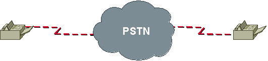
This illustration shows a traditional fax call over PSTN.
Page 4
Some capabilities that are exchanged and negotiated are page transmission speed, Error Correction Mode
(ECM), resolution, page coding, and scan time.
Page transmission speed (training) is an important negotiation that determines the speed at which the fax
sends its information.
Faxes try to train at the highest modulation speed possible based on the parameters exchanged initially. Fax
devices retrain to a lower speed if the training at a higher speed fails.
Page transmission occurs when the training part of the fax negotiation phase is complete with the use of the
previously agreed upon parameters. The page information is coded into scan lines with a standard resolution
of 203H x 98V dots per inch.
Fax images are typically compressed and encoded with either Modified Huffman (MH) or Modified Read
(MR) encoding. MH usually compresses at a 20:1 ratio. MR encoding typically provides a 20 percent
compression improvement over MH but is slightly less resilient to error.
When page transmission occurs, a bit rate is used that is higher than the initial 300 BPS that is used in the
call setup negotiation. The bit rate used for the page transmission is confirmed within training.
These are some of the common rates used in fax page transmission:
V.27ter – 2400/4800 BPS
•
V.29 – 7200/9600 BPS
•
V.17 – 14400 BPS
•
Note: These V.XX specifications used for page transmission (V.27ter, V.29, V.17) and fax negotiation
(V.21) are specifications that define how digital data is to be sent over analog phone lines.
Data modems are also able to use these specifications even though most data modems have migrated to
much faster speeds.
Fax Relay Basics
Fax relay is a technique used to overcome the deficiency in high compression voice codecs (G729, g723,
and the like) when these codecs try to pass fax traffic.
Because a fax call is treated as if it is a regular speech call, the DSP in each gateway is put into voice mode,
after which human speech is expected to be received and processed.
Within the life of the call, if a fax answer (CED) or call (CNG) tone is heard, the DSP does not interfere
with the speech processing. It allows the tone to continue across the VoX call leg.
Page 5
A normal fax machine, after it generates a CED or hears a CNG, transmits a T.30 DIS message as part of a
fax handshake. This process usually occurs at the termination fax machine.
The DSP of the termination gateway then detects the HDLC flag sequence at the start of the DIS message
and initiate fax relay switchover. This means that it unloads the voice codec and loads a fax codec to handle
the fax call that takes place.
Notification is also sent to the DSP on the other side of the VoX network so that the DSPs on each side of
the fax call use the fax codec. Dependent on the fax relay protocol used, the notification mechanisms differ.
With the fax codec loaded, the DSPs demodulate the T.30 HDLC frames, extract the fax information, and
pass it between the routers with one of these fax relay protocols:
Proprietary Cisco fax relay for VoIP – Fax relay is the default mode to pass faxes through a VoIP
network, and Cisco fax relay is the default fax relay type. This capability has been supported in Cisco
IOS Software Releases 11.3 and later, is widely available, and uses RTP to transport the fax data.
•
Standards-based T.38 fax for VoIP – T.38 has been available in Cisco IOS Software Releases
12.1(3)T and later on some platforms. It can be enabled with the fax relay protocol t38 command
configured under the VoIP dial peer and uses UDP to transport fax data.
•
Standards-based FRF.11 Annex D for VoFR and VoATM.
•
Unlike inband faxes or fax passthrough, fax relay breaks down the T.30 fax tones into their specific HDLC
frames (demodulation), transmits the information across the VoX network with the fax relay protocol, and
then converts the bits back into tones at the far side (modulation).
The fax machines on either end send and receive tones and are not aware of a demodulation/modulation fax
relay process.
Cisco fax relay and T.38 fax relay also differ from T.37 fax store and forward. T.37 provides a standards-
based method to allow a VoIP gateway to receive this:
Most Cisco voice gateways currently support two methods to transmit fax traffic across the IP network:
Fax Pass-Through—In fax pass-through mode, the gateways do not distinguish a fax call from a voice
call
1.
Cisco Fax Relay— In fax relay mode, the gateways terminate the T.30 fax signaling
2.
Cisco fax relay and T.38 fax relay also differ from T.37 fax store and forward. T.37 provides a standards-
based method to allow a VoIP gateway to receive this:
A fax from a fax machine and forward it to an SMTP-capable mail server. The mail server can then
deliver the fax to a user as an email message.
•
An email message from a mail server and modulate it into a fax signal for receipt by a regular fax
machine.
•
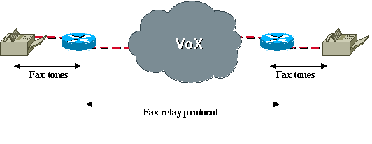
This diagram illustrates fax relay over a VoX network. The fax connection to the origination and termination
gateways can be directly into FXS ports on the gateway, or can be via a PBX or the PSTN into an E1, Basic
Rate Interface (BRI), FXO, or E&M port on the gateway.
Page 6
Configuration Considerations
Fax relay is on by default on VoIP/VoFR/VoATM platforms such as the Cisco 3810, 2600, 3600, and 5300.
If voice calls complete successfully between two routers, fax calls are supposed work, but when fax relay
does not work or performance needs to be improved, there are some fax relay specific commands that you
can issue as a precursor to troubleshoot the problem:
fax rate
•
fax-relay ECM disable
•
fax NSF
•
fax protocol
•
fax rate Command
The fax rate command is configured under the VoFR or VoIP dial-peer in configuration mode. The default
setting is fax rate voice and this does not appear in the configuration under each dial-peer.
fax rate Command
<#root>
vnt-3660-23(config-dial-peer)#
fax rate ?
12000 FAX 12000 BPS
14400 FAX 14400 BPS
2400 FAX 2400 BPS
4800 FAX 4800 BPS
7200 FAX 7200 BPS
9600 FAX 9600 BPS
disable Disable Fax Relay
voice Highest possible speed allowed by voice rate
The fax rate voice setting restricts the fax rate to the codec bandwidth. This restriction means that, if the
Page 7
dial-peer is configured to use the default G.729 voice codec that compresses voice to 8 kbps, the fax rate
voice setting would not allow fax calls to exceed this codec bandwidth.
The fax would be limited to a bandwidth of 7200 BPS, even if it tried to initially negotiate at a higher
bandwidth of 14400 BPS or 9600 BPS.
A common complaint is that faxes that had completed within a certain time when connected via the PSTN
now take twice as long. If a low bandwidth codec such as g729 has been configured with the default fax rate
voice setting, this behavior is expected.
With the fax rate command, it is possible to configure fax transmissions to use a bandwidth greater than the
codec compression.
The command fax rate 14400 allows fax calls to negotiate to a maximum of 14400 BPS regardless of the
voice codec configured. This configuration resolves the problem of longer completion times.
The main purpose served by the fax rate command within VoX networks is to provide deterministic
bandwidth usage per call.
The fax rate voice setting is the default because it ensures that both voice and fax calls use the same amount
of bandwidth within the VoX network. This consideration is understood when the fax rate is changed to
something greater than that of the codec bandwidth.
In addition, some fax machines can operate more stably at a rate different from the default. In this case, the
fax rate command can be used to test operation at different speeds.
Note from the router output that fax relay can also be disabled if you issue the fax rate command. A valid
troubleshooting technique is to disable fax relay and configure high bandwidth codecs such as G711.
This technique is discussed in the "Troubleshooting" section under 6. Disable Fax Relay and Change Codec
for Passthrough.
fax-relay ECM disable Command
The fax-relay ECM disable command is available for Cisco proprietary fax relay only and is issued to
disable Error Correction Mode (ECM) negotiation between a pair of fax machines.
ECM ensures that the faxed pages are transmitted error free and is a feature that is usually found on higher
end models.
Unfortunately, ECM has a low tolerance (approximately two percent) for jitter and packet loss, but when
this negotiated feature is enabled, it can result in a higher fax failure rate in lossy VoX networks. Incomplete
output on the termination fax is a symptom of failures due to packet loss.
If both fax machines agree within the fax negotiation phase, ECM is enabled, but within fax relay the routers
demodulate the fax tones into their true HDLC frame format.
As a result, the routers are able to intercept and overwrite the field in the frame that indicates ECM status. If
a fax machine transmits that it is capable of ECM, the router can change this parameter so that the other fax
machine believes that ECM is not supported.
Both fax machines are then forced to disable ECM, which means the fax data must be transmitted with
standard T.4 data.
Fax reliability is increased greatly with ECM disabled, even with much higher packet loss (about 10 percent)
Page 8
and delay. In addition, this command automatically enables a Cisco IOS feature called packet loss
concealment whereby lost scan lines are repeated to spoof the fax machine to believe that it has received all
the data.
Note that, while ECM can improve the success rate of fax transmissions in lossy VoX networks, the basic
network problems remain and are to be addressed prior to the occurrence of other problems.
A straightforward configuration step performed under the VoIP dial-peer is to disable ECM. As noted in the
command reference, this command currently works only for VoIP dial-peers. It can be configurable for
VoFR and VoATM, but it does not disable ECM.
fax-relay ECM disable Command
<#root>
vnt-3660-23(config-dial-peer)#
fax-relay ECM ?
disable Disables ECM mode for fax relay
fax NSF Command
The fax NSF command is used to prevent the transfer of proprietary fax capabilities. Because the fax relay
implementation of the router demodulates and decodes the fax tones based on the T.30 specification,
transactions or encoding that are proprietary break fax relay and cause the fax transmission to fail. Certain
brands of fax machines use these proprietary encodings to signal the the availability of enhanced
capabilities, which help a fax manufacturer distinguish its products from others. This capability notification
takes place with the optional Non Standard Facilities (NSF) field within fax negotiation.
When you issue the fax NSF command, the router overwrites the NSF, so only standard fax transactions
occurs. Vendor-specific facilities that are beyond the standard Group 3 requirements, and that break Cisco
fax relay, is not usable. Usually the NSF is set to all zeros when this command is issued, and this fixes
problems caused by the NSF field.
fax NSF Command
<#root>
vnt-3660-23(config-dial-peer)#
fax NSF ?
WORD Two-digit country code + four-digit manufacturer code
vnt-3660-23(config-dial-peer)#
fax NSF 000000
fax protocol Command
The fax protocol command is required for VoIP to specify which fax relay protocol (T.38 or Cisco fax
relay) is used.
fax protocol Command
Page 9
<#root>
vnt-3660-23(config-dial-peer)#
dial-peer voice 3 voip
vnt-3660-23(config-dial-peer)#
fax protocol ?
cisco Use Cisco proprietary protocol
system Use choice specified in global fax protocol CLI
t38 Use T.38 protocol
The cisco option configures Cisco fax relay. The t38 option disables Cisco fax relay and enables T.38.
Certain voice platforms such as the Cisco 5350 and 5400 support only T.38. For interoperability, T.38 must
be explicitly configured on platforms where Cisco fax relay is the default. The system option allows the dial-
peer to inherit the fax relay protocol that is configured globally with the voice service voip command. If
nothing is configured under the voice service voip command, the default is Cisco fax relay.
The default setting of the fax protocol command is the system option. Because the system option defaults to
Cisco fax relay, VoIP dial-peers always default to Cisco fax relay when nothing is explicitly configured
globally.
<snip>
!
voice service voip
!
!--- Note that there is no fax protocol configured so the !--- default is Cisco fax relay. Any dial-pee
<snip>
!
dial-peer voice 3 voip
destination-pattern 1000
session target ipv4:10.1.1.1
!
!--- Note that because fax protocol is not configured under !--- this VoIP dial-peer, the default is fa
<snip>
Troubleshooting
These steps have been shown to resolve the majority of issues that involve fax relay over VoIP, VoATM,
and VoFR. Information that is specific to a particular encapsulation type or fax relay type is noted.
- Identify and Isolate the Problem
The first step to take when you troubleshoot any fax relay issue is to reduce the problem to its simplest form.
Page 10
Many issues arise in situations where multiple fax machines are not able to pass fax traffic. It is easiest to
isolate two fax machines that have problems and concentrate on a simple topology. Determine how these
machines are connected to one another and resolve the issue between this pair first. In addition, it is advised
to draw a complete picture of the topology and determine how the fax machines are interconnected.
To troubleshoot one issue at a time minimizes confusion and allows for methodical troubleshooting. It is
also possible that the solution for this problem resolves other fax relay problems in the network. Most fax
relay problems result from poor VoX configuration or network design. These lead to basic connectivity
problems and physical line or packet loss and jitter problems.
After you have identified and isolated the problem, the next steps are to verify the basic VoX configuration
and monitor the health of the network.
2. Check Basic Connectivity
Basic fax connectivity issues can be the result of these factors:
Normal voice connectivity problems.
Confirm that normal voice calls can be completed before you investigate fax connectivity. If there is
no telephone attached, unplug the fax machine and connect a regular telephone. If normal voice calls
do not connect, the issue is possibly VoX-related, and you can troubleshoot the problem as a normal
voice connectivity issue before you proceed with fax troubleshooting.
1.
Configuration problems related to dial peers such as these:
Wrong dial peer matched.
After you ensure that voice calls can be successfully completed in both directions through the
VoX network, issue the show call active voice brief command and note the dial peers that are
matched with each voice call.
•
2.
Page 11
Note: Note: When you have VoIP trunks, you are able to see all the call legs with the
show call active voice brief command. In some versions of Cisco IOS Software
Release 12.2, there is a bug in the show call active command and a fax call that comes
through a VoIP trunk no longer appears. When you issue a show call active fax brief
command, the call is now listed. For more information about this bug, see Cisco bug
ID CSCdx50212

Page 12
and Cisco bug ID CSCdv02561
.

Page 13
Note: Note: Ensure that the configured dial peer is the peer that is matched. In this
command output, you can see that the outbound VoIP call leg uses peer ID 100.
show call active voice brief Command
<#root>
ms-3640-13b#
show call active voice brief
<snip>
Total call-legs: 2
1218 : 51710253hs.1 +415 pid:400 Answer 400 active
dur 00:01:08 tx:3411/68220 rx:3410/68200
Tele 3/0/0:43: TX:68200/6820/0ms g729r8 noise:0 acom:2
i/0:-51/-44 dBm
1218 : 51710396hs.1 +272
pid:100 Originate
100 active
dur 00:01:09 TX:3466/69320 rx:3467/69340

Page 14
IP
2.1.1.2:17092 rtt:56ms pl:64730/0ms lost:0/1/0
delay:69/69/70ms
g729r8
Total call-legs: 2
A common cause of fax relay problems is that the correctly configured dial peer is not the one
that is matched. It is also common that there is no particular inbound VoIP dial-peer configured
on the termination gateway, and Cisco IOS Software selects the first appropriate (and default)
VoIP dial peer as the inbound dial peer. The parameters for this inbound dial peer possibly do
not match those of the outbound dial peer on the origination gateway.
It is not always required that you have identical configurations on the outbound and inbound
VoIP dial-peers. When you have a fax relay problem, though, make sure you have a dedicated
inbound VoIP dial-peer on the termination router and that its configuration matches the
configuration of the outbound VoIP dial-peer on the origination router. This configuration for
ISDN-connected routers is an example of specific, matched VoIP dial peers for the destination
pattern "5..." outbound on the origination gateway and inbound on the termination gateway.
Originating Gateway
Terminating Gateway
!--- Incoming POTS peer:
Dial-peer voice 1 pots
Incoming called number.
Direct-inward-dial
Port 1/0:15
!--- Outgoing VoIP peer:
Dial-peer voice 2 voip
Destination-pattern 5…
Session target ipv4:10.10.10.10
Fax rate 14400
fax protocol t38
ls-redundancy 0
hs-redundancy 0
!--- Outgoing POTS peer
:
Dial-peer voice 10 pots
Destination-pattern 5…
No digit-strip
Port 2/0:15
!--- Incoming VoIP peer:
Dial-peer voice 20 voip
Incoming called-number 5…
Fax rate 14400
fax protocol t38
Ls-redundancy 0
Hs-redundancy 0
More information on matched dial peers both inbound and outbound, VoIP, and POTS can be
found in Voice - Understanding How Inbound and Outbound Dial Peers are Matched on Cisco
IOS Platforms.
Another method you can use to check dial peer matches is to issue the debug voip ccapi inout
command. The debug output from this command shows an ssaSetupPeer message that lists all
the dial-peers that match the called number. A ccCallSetupRequest message follows with the
outbound peer option that indicates the outbound VoIP dial-peer selected. When multiple VoIP
dial peers are configured for the same destination, it is possible that the initial call setup fails
and another dial peer tried. In this case another ccCallSetupRequest appears in the debug.
debug voip ccapi inout - Originating Gateway
Page 15
<#root>
.Jun 4 21:06:43.461:
ssaSetupPeer
cid(19)
peer list: tag(400) called number (5074)
.Jun 4 21:06:43.461:
ccCallSetupRequest
(Inbound call = 0x13,
outbound peer =100
,
dest=, params=0x62F1CC70 mode=0, *callID=0x62F1CFD8,
prog_ind = 0)
On the termination voice gateway, the first line of the debug voip ccapi inout call trace (as
shown here) is a cc_api_call_setup_ind message with a peer_tag option that refers to the
inbound VoIP dial peer on the termination gateway.
debug voip ccapi inout - Terminating Gateway
<#root>
.Jun 4 21:06:43.461:
cc_API_call_setup_ind
(vdbPtr=0x62F07650,
callInfo={called=5074,called_oct3=0x80,
calling=5075, calling_oct3=0x0,>calling_oct3a=0x83,
calling_xlated=false,
subscriber_type_str=Unknown,fdest=1,
peer_tag=400
, prog_ind=0},callID=0x635F72D0)
Incorrectly configured dial peers on one or both sides
After you confirm that the correct dial peer is matched (in this case dial-peer 100 for the
origination gateway and dial peer 400 for the termination router), confirm in the configuration
that the dial-peer is configured correctly for fax. Some common errors to check for on both
sides of the call are these:
Fax relay is disabled (that is, the fax rate disable command has been issued on the dial
peer) while a low bandwidth codec has been in use.
○
The dial peer on one voice gateway is configured for Cisco fax relay, but the other voice
gateway is a Cisco 5350/5400. The Cisco 5350/5400s only support T.38, so the
negotiation fails.
○
•
Page 16
The default dial peer that is used inbound on the termination gateway and default
parameters do not match with the outbound dial peer on the origination gateway.
○
Incorrect Compand Type
The companding type for the US is µ-law; for Europe and Asia, it is a-law. You can issue the
show voice call command to see which value is currently configured. If on a BRI or E1 port,
the companding type on the router does not match the one on the connected device, and calls
sometimes fail and sometimes connect, but the voice becomes heavily distorted so that the
person becomes unrecognizable and a high low-pitch noise level appears.
In Cisco IOS Software Release 12.2(3), the compand-type command is not on on the BRI ports,
and the companding type is the default value. For more information about this bug, see Cisco
bug ID CSCdv00152 and Cisco bug ID CSCdv01861.
•
Other basic connectivity problems not related to dial peers include these:
Cisco IOS Software incompatibilities on gateway pairs.
Again, it is not always required that Cisco IOS Software releases match, but it is recommended
to check releases when problems occur.
•
Compressed Real-Time Transport Protocol (cRTP).
There are several known problems associated with cRTP. Fixes are available for these
problems, and it makes sense to disable cRTP when problems occur to check whether a Cisco
IOS Software upgrade is an appropriate course of action.
•
On Cisco AS5300 voice gateways, ensure that the VCWare and Cisco IOS Software are
compatible.
•
3.
Fax connectivity problems across the PSTN.
If voice calls work in both directions but fax calls fail in at least one direction, check that normal faxes
between these two machines works across the PSTN. In other words, ensure that the fax machines
successfully transmit faxes to each other with the PSTN without traversing the VoX network. If they
do not, the fax machines can have problems that need to be addressed before you consider fax relay
problems.
4.
3. Check for SLIPs and Other Errors on Digital Interfaces
If there are any T1 or E1 digital connections used by the routers that perform fax relay, make sure that they
are error free. Fax relay is very sensitive to errors on digital interfaces, especially slips. The errors is not
noticeable on voice calls but they can cause faxes to fail.
show controller T1(E1) 1/0 Command
<#root>
vnt-3660-23c#
show contr t1 1/0
T1 1/0 is up.
Applique type is Channelized T1
Cablelength is long gain36 0db
No alarms detected.
Page 17
alarm-trigger is not set
Version info Firmware: 20010805, FPGA: 15
Framing is ESF, Line Code is B8ZS,
Clock Source is Line.
Data in current interval (132 seconds elapsed):
0 Line Code Violations, 0 Path Code Violations
0 Slip Secs
, 0 Fr Loss Secs, 0 Line Err Secs,
0 Degraded Mins
0 Errored Secs, 0 Bursty Err Secs, 0 Severely Err Secs,
0 Unavail Secs
The T1 or E1 controllers at both origination and termination gateways are typically error free. If errors
occur, repeat the show controller (T1, E1, and 1/0 varies) command several times within the call to see if
the number of errors increases. The most common problem of slips is a synchronization problem that results
in clocking errors.
In packet voice networks, it is usually sufficient to confirm that the router clocks from the line. If it does not,
ensure the clock source line command is entered at the controller level, but in VoATM or TDM networks,
where a clocking hierarchy is established and the routers need to pass clock through the network, additional
considerations need to be made. The Clocking Plan document provides more information about synchronous
clocking.
On 26xx / 366x routers, when you use the AIM VOICE card, the controller shows "controlled slips" unless
you add the network-clock-participate and network-clock-select commands.
On the Cisco MC3810 platform, you need to configure the network-clock-select command and issue the
show network-clock command to make sure the configuration has taken effect.
On the Cisco 7200VXR platform, the frame-clock-select command is required for the voice cards. This
command is particularly important for the 7200VXR voice gateways because, by default, the internal TDM
bus is not driven by the local oscillator. Because the E1 trunks are normally synchronized to the telephony
network, the result is hidden clocking errors and intermittent fax transmission problems. More detail is
available in Cisco bug ID CSCdv10359.
On the C4224 MFT cards, when they are to accept the clock from the line, under the controller t1 x/y you
need to issue the clock source loop-timed command. This setting decouples the controller clock from the
system-wide clock. It is then required to set the network-clock-select command. In this case, it would be
network-clock-select 1 t1 x/y.
4. Check Fax Interface-type
On some platforms, which include the Cisco 3660, 5300, 5350, 5400, and 5800, the router defaults to fax
interface-type modem. The fax interface-type modem global configuration command forces fax calls to a
modem (usually for T.37 Store and Forward fax) and not to a DSP. For Cisco fax relay to work, the fax call
must be sent to a DSP, which means it must be configured with the fax interface-type vfc command.
fax interface-type Command
<#root>
vnt-3660-23c(config)#
Page 18
fax interface-type ?
modem Use modem card
vfc Use Voice Feature Card
vnt-3660-23c(config)#
fax interface-type vfc
You must reload the router
Make sure you reload the router, or the command does not take effect. Fax calls fail on the platforms with
Cisco fax relay (or T.38), so this is an important command to check.
The fax interface-type vfc command was not necessary in Cisco IOS Software releases prior to 12.2. The
problem is commonly seen when one of the voice gateways is upgraded to Cisco IOS Software Release 12.2
or later.
5. Make Sure that the Fax Codec is Loaded During the Fax Call
Each fax machine displays the remote fax machine ID on its LCD screen at the completion of the fax
negotiation phase. It is unlikely that the fax machines could complete negotiation if the fax codec had not
been successfully downloaded. On the other hand, if no remote fax machine ID is displayed, further
debugging in this area is appropriate.
There are two ways to make sure that the voice gateways detect the fax transmission and successfully load
the fax codec.
Issue the debug vtsp all command and the debug voip ccapi inout call trace. These debugs are
discussed in detail in the Debugging section of this document.
1.
Issue the show voice trace command. Show commands are less resource intensive on the router than
debug commands and are preferable in production networks. This is an example output from a show
voice trace command on an ISDN interface.
2.
show voice trace Command
<#root>
BrisVG200gwy01#
show voice trace 1/0:15
1/0:15 1
1/0:15 2
1/0:15 3
1/0:15 4
1/0:15 5
1/0:15 6
1/0:15 7
1/0:15 8
1/0:15 9
1/0:15 10 State Transitions: timestamp (state, event) -> ...
63513.792 (S_SETUP_REQUEST, E_TSP_PROCEEDING) ->
63515.264 (S_SETUP_REQ_PROC, E_TSP_ALERT) ->
63515.264 (S_SETUP_REQ_PROC, E_CC_BRIDGE) ->
63515.332 (S_SETUP_REQ_PROC, E_CC_CAPS_IND) ->
63515.332 (S_SETUP_REQ_PROC, E_CC_CAPS_ACK) ->
Page 19
63515.348 (S_SETUP_REQ_PROC, E_CC_CAPS_IND) ->
63515.348 (S_SETUP_REQ_PROC, E_CC_CAPS_ACK) ->
63515.356 (S_SETUP_REQ_PROC, E_CC_CAPS_IND) ->
63515.356 (S_SETUP_REQ_PROC, E_CC_CAPS_ACK) ->
63518.656 (S_SETUP_REQ_PROC, E_CC_REQ_PACK_STAT) ->
63518.660 (S_SETUP_REQ_PROC, E_DSP_GET_VP_DELAY) ->
63518.660 (S_SETUP_REQ_PROC, E_DSP_GET_VP_ERROR) ->
63518.660 (S_SETUP_REQ_PROC, E_DSP_GET_RX) ->
63518.660 (S_SETUP_REQ_PROC, E_DSP_GET_TX) ->
63521.028 (S_SETUP_REQ_PROC, E_CC_REQ_PACK_STAT) ->
63521.028 (S_SETUP_REQ_PROC, E_DSP_GET_VP_DELAY) ->
63521.028 (S_SETUP_REQ_PROC, E_DSP_GET_VP_ERROR) ->
63521.028 (S_SETUP_REQ_PROC, E_DSP_GET_RX) ->
63521.028 (S_SETUP_REQ_PROC, E_DSP_GET_TX) ->
63524.128 (S_SETUP_REQ_PROC, E_TSP_CONNECT) ->
!--- Fax tone detected:
63529.352 (S_CONNECT, E_DSP_TONE_DETECT) ->
63529.356 (S_LFAX_WAIT_ACK, E_PH_CODEC_ACK) ->
!--- Fax codec being downloaded to DSPs:
63529.356 (S_LFAX_DOWNLOAD, E_pH_CODEC_FAX) ->
63529.356 (S_LFAX_DOWNLOAD, E_DSPRM_PEND_SUCCESS) ->
- Disable Fax Relay and Change Codec for Passthrough
In the previous steps, you established that voice calls work, faxes work through PSTN, and all digital
interfaces in the fax relay path are free from errors. This step determines whether faxes can go through with
fax relay disabled. Under the VoIP/VoATM/VoFR dial-peers, enter this:
fax rate disable Command
<#root>
vnt-3660-23(config)#
voice-port 2/0:15
vnt-3660-23(config-voiceport)#
no echo-cancel enable
vnt-3660-23(config)#
dial-p voice 3
vnt-3660-23(config-dial-peer)#
fax rate disable
vnt-3660-23(config-dial-peer)#
codec g711ulaw
vnt-3660-23(config-dial-peer)#
no vad
Page 20
Make sure these commands are entered on both gateways. These commands disable fax relay, disable echo
cancellation, and force the call to use a high bandwidth codec without VAD. The router then samples the
tones like a normal voice call, and, with the high bandwidth codec (G.711), the most precise sample possible
is captured. The tone to be replayed on the other side is as accurate as possible. The caveat to this step is
that, because G.711 is a 64 kbps bandwidth codec, each call consumes up to 80 kbps (for VoIP) when
additional transport protocol overhead is added.
If this test is positive, two things have been accomplished. First, if per call bandwidth consumption is not a
major issue for the network, there is now a potential fax passthrough workaround for the fax relay problem.
Secondly, and more significantly, if bandwidth consumption is an issue, the problem has been isolated to the
fax relay software, and a TAC case is to be opened.
If this test fails, it is likely that whatever causes the fax calls to fail with fax relay also causes the failures
with this test. What comes to mind first is that the network can have a large amount of jitter or packet loss.
7. Check for Packet Loss on the VoX Network
The easiest and most accurate way to determine if there is a packet loss is to do this:
Disable VAD on the VoX dial-peers.
1.
Make a voice call between the same ports where the fax machines are connected. (Fax machines can
serve as ordinary phones, or you can connect the handsets to the same ports where the fax machines
are connected).
2.
When the call is connected, do this:
Issue the show voice dsp command. You can see in the output that one of the DSP channels has
the configured codec loaded. Usually the column "TX/RX-PAK CNT" shows that the transmit
and receive packet counters are equal, which means that no packets are lost. If the counters are
not equal, packets possibly become lost. Type the show voice dsp command several times at
30-second intervals to determine if the difference increases and packets are lost.
a.
Issue the show voice call summary command to see which port (and time slot if applicable) is
allocated to the voice call. Type terminal monitor and then issue the show voice call command
with the voice port (and time slot if applicable) to get the detailed DSP statistics. In the
"DSP VOICE VP_ERROR STATISTICS" section of the output, look for the counters.
They are usually 0 or less than 20. If the counter(s) is higher than 20, investigate the packet loss.
b.
3.
If the network appears to be lossy, it is not reasonable to expect fax relay to work reliably. It is possible to
disable ECM, but further investigation is probably needed to ensure that QoS is provisioned end-to-end so
that the Voice and Fax relay traffic has priority and is never lost within the congestion. The Related
Information section contains more information about how to troubleshoot voice quality problems.
8. Disable Fax Relay ECM (Cisco Proprietary VoIP Only)
For networks with packet loss and lots of jitter, disable ECM to improve fax relay calls. Issue the command
fax-relay ECM disable (discussed in more detail in the Configuration section of this document) to turn off
ECM so that a larger amount of jitter and packet loss can be tolerated.
Issue the fax-relay ECM disable command to improve fax relay performance in lossy networks, but this
command is also recommended for basic troubleshooting. Even if there is not a noticeable jitter problem in
the network, this command can sometimes help determine fax relay problems. This command is available
under VoFR and VoATM dial-peers but currently works only for VoIP.
Page 21
Note: This command also activates the packet loss concealment feature.
fax-relay ECM disable Command
<#root>
vnt-3660-23(config-dial-peer)#
dial-peer voice 3
vnt-3660-23(config-dial-peer)#
fax-relay ECM disable
- Enable T.38 Packet Redundancy (T.38 VoIP Only)
If T.38 for VoIP is used as the fax relay protocol, the T.38 packet redundancy feature can be turned on if
you configure this command under the appropriate dial peers on both gateways:
T.38 Packet Redundancy
<#root>
vnt-3660-23(config-dial-peer)#
fax protocol t38
Ls-redundancy X Hs-redundancy Y
where X > 0 and Y = 0 (only make changes to Ls-redundancy)
If Cisco proprietary fax relay is in use, an alternative or additional option to disable ECM is to change fax
relay protocol to T.38 so that the T.38 packet redundancy feature can be tested. This feature can alleviate
failure due to packet loss, but note that T.38 Packet Redundancy significantly increases bandwidth usage,
and it is preferable to eliminate the packet loss where possible.
10. Set the fax NSF Command to All Zeroes
The fax NSF command can be helpful for the brands of fax machines that alter the NSF field within fax
negotiation for proprietary encodings. This command allows the router that does fax relay to override the
settings made by the fax machines that attempts to implement proprietary encodings. Before the fax NSF
command was available, fax relay would fail for these brands of fax machines. Typically the fax NSF
command is used to set the NSF field to all zeroes, which forces a standard fax negotiation from both sides.
This command has been successful with certain brands such as Harris and Lanier, and it is recommended
when fax relay fails.
fax NSF Command
<#root>
vnt-3660-23(config-dial-peer)#
Page 22
fax NSF 000000
- Check if the MGCP Gateway is Configured for the FXR Package
When the T.38 fax calls to the fax server from the PSTN fail and if the Cisco Unified Communications
Manager traces show support_FXR=0, then the FXR package configuration can be missing from the MGCP
gateway. In this case, add these commands to the MGCP gateway:
<#root>
no mgcp fax t38 inhibit
mgcp package-capability
fxr-package
mgcp default-package
fxr-package
After this, reset the gateway and the fax calls start to work.
12. Final Stages of Resolution
If the previous troubleshooting steps did not resolve the fax relay issue, the problem possibly requires more
advanced troubleshooting. These are additional steps to try before you open a case with the Cisco Technical
Assistance Center (TAC):
Learn the brands and models of the fax machines that fail, and investigate those brands and
models for known issues.
Sometimes there are CARE cases or bugs that address problems for a certain brand of fax machine.
For example, a search on Bug Search Tool (registered customers only) for a Pitney Bowes fax shows
a bug with Pitney Bowes fax machines and Cisco fax relay (Cisco bug ID CSCdu78373 (registered
customers only) ). This bug is not in the Cisco IOS Software but is an incompatibility with Pitney
Bowes' proprietary fax signaling protocol when the fax devices on each side of a connection are
Pitney Bowes 9920s or 9930s. The workaround is to disable the proprietary protocol on the fax
machines or to disable fax relay and use a higher bandwidth codec.
Known Caveats
Known caveats are unexpected behaviors or defects in the software releases for a product. This table
contains information on known problems for fax support on Cisco voice gateways.
If you have a CCO account, you can search for known problems on the Cisco bug tracker system tool,
called Bug Search Tool. To access Bug Search Tool, do one of these tasks:
Enter https://bst.cloudapps.cisco.com/bugsearch/ in your web browser.
○
Table 1 Known Caveats
Bug ID
Summary
Explanation
VAD introduces severe
When Cisco voice gateways are configured for fax pass-
CSCdu30250
•

Page 23
errors in fax pass-through
mode.
through mode, disable Voice Activity Detection (VAD) on
all VoIP dial-peers associated with the fax calls. To disable
VAD on a VoIP dial-peer, use these commands:
<#root>
config terminal
dial-peer voice XXX voip
no vad
CSCdu62269
CSCdu62269
Any Cisco gateway device that initiates a fax relay call
(with RTP packets with payload type 96) to a WS-X4604-
GW in gateway mode fails. This has been resolved in
12.1.5YF3. When set to gateway mode, the software now
identifies payload type 96 and initiates a pass-through
mode.
CSCdv08143
Fax transmissions of 5-30
pages fail with fax pass-
through mode from the
VG248 to the WS-X4604-
GW in gateway mode.
This failure only occurs with software image 12.1.5YF2 on
the WS-X4604-GW. To avoid this error, use 12.1.5YF1,
12.1.5YF3, or later.
CSCdv83401
CSCdv83337
On Cisco Catalyst 6000
switches, when a fax or
modem tone is detected,
the call is switched into
fax pass-through mode
with 10ms (134 byte)
packets.
Frame size in fax pass-through mode is 214 bytes. Faxes do
not fail even though the packet size is incorrect.
CSCdw07735
Fax transmissions fail
with fax pass-through
mode from the WS-
X4604/VIC-2FXS (only)
to the WS-X6624-FXS
gateway with Cisco
CallManager 3-1-2c_spA
load A00203010026. The
WS-X4604 / VIC-2FXS
exhibits this in both
gateway and toll-by-pass
modes.
This failure occurs with software images 12.1.5YF2 and
12.1.5YF3 on the WS-X4604-GW, and is fixed in 12.2(7)X
software.
CSCdw07804
Fax transmissions fail
with fax pass-through
mode from the WS-
C4224V / VIC-2FXS
(only) to the WS-X6624-
FXS gateway with Cisco
CallManager 3-1-2c_spA
load A00203010026.
This failure occurs with software images 12.1.5YE2 and
12.1.5YE4 on the WS-C4224V and are fixed in 12.2(7)X
software.
Use search tools to look for known fax problems in the Cisco IOS Software release where the
problem occurs.
In the previous step, searches were made for a specific fax brand to identify a known issue between a
certain fax brand and the Cisco fax relay code. The next step is to perform a generic search because
•

Page 24
there could be a fax relay bug in the Cisco IOS Software release installed.
For example, if a fax relay that uses VoFR does not work in Cisco IOS Software Release 12.1(2)T,
you can search for bugs with the Bug Toolkit on CCO. In this example, use these values:
Major Version: 12.1
○
Revision: 2
○
Feature/component: VoFR
○
Keyword: fax
○
One of the bugs is Cisco bug ID CSCdr65984 (registered customers only) , entitled "fax doesnt work
for vofr." This bug caused all fax relay to fail for VoFR, and an upgrade is needed to a Cisco IOS
Software release in which this bug is no longer present.
Eliminate hardware faults.
In some cases, it is easier to isolate the problem if you exclude potential problem sources, one by one.
Replace different hardware parts and use alternative IP connections between the gateways. When
extra hardware is available, these steps can help:
Use different ports on the routers.
If your configuration involves two gateways connected to the PBXs or PSTN with E1 or T1 and
if you have the FXS ports available, try to connect the fax machines directly to the FXS ports on
the voice gateways. This procedure helps further isolate the problem when the possibility of the
E1-card failure, problems on the telephony side, or E1 synchronization or cable problems are
excluded.
○
Try different hardware.
If you have another voice gateway with FXS ports available to you, try to connect it directly
with the Ethernet crossover cable to each of the voice gateways and send a fax with the fax
machine connected to the FXS port. This procedure helps determine if there are problems in the
VoX network such as queuing, fragmentation, or prioritization.
○
•
Use debug commands on the router to determine the problem.
See the "Debugging" section for details about debug commands useful for troubleshooting fax relay
problems.
•
Debugging
T.30 Messages
The debugs can be difficult to understand if you are not familiar with the messaging that occurs within a
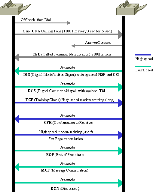
typical fax transmission. This is a graphical representation of the basic T.30 transactions that occur for a
single page fax transmission.
Page 25
The description of the details of these transactions is beyond the scope of this document, but these are
definitions of the basic transactions that are seen within fax relay. The list is alphabetical for quick reference
and includes messages that are commonly seen when debugging Cisco fax relay. For more in-depth
information on this messaging or for information on messages that are not listed here, see the T.30
specification.
Page 26
CED (Called terminal identification) – a 2100 Hz signal that is transmitted by the termination fax
device upon answering a fax call. This signal temporarily disables echo cancellers that are present on
the connection to prepare the line for data transmission.
•
CFR (Confirmation To Receive) – a response that confirms that the previous messaging and training
has been completed and that fax page transmission can begin.
•
CNG (Calling Tone) – an 1100 Hz tone that is on for half a second and then off for 3 seconds. This
signal identifies the fax terminal as a non-speech device. The signal also indicates that the initiating
fax terminal awaits the DIS signal from the termination fax terminal.
•
CRP (Command Repeat) – a response that indicates that the previous command was received in
error and needs to be repeated. (Optional)
•
CSI (Called Subscriber Identification) – is used to provide the specific identity of the called fax
terminal through its international telephone number. (Optional)
•
DCN (Disconnect) – ends the fax call and requires no response.
•
DIS (Digital Identification Signal) – identifies the capabilities of the called fax terminal.
•
DTC (Digital Transmit Command) – the response to the capabilities identified by the DIS signal.
Here is where the calling fax terminal matches its capabilities with the ones provided in the DIS
message of the called fax terminal.
•
EOM (End Of Message) – indicates the end of a complete page of fax information.
•
EOP (End Of Procedure) – indicates the end of a complete page of fax information and no further
pages are to be sent. Proceed to the disconnect phase of the fax call.
•
FTT (Failure To Train) – used to reject a training signal and request a retrain (the retrains usually
occur at lower modulation speeds).
•
MCF (Message Confirmation) – indicates that a message has been satisfactorily received.
•
MPS (MultiPage Signal) – indicates the end of a complete page of fax information and that the
receiver is ready for additional pages.
•
NSF (Non-Standard Facilities) – is used to identify specific capabilities or requirements that are not
covered by the T-series specifications. (Optional)
•
RTN (Retrain Negative) – indicates that a previous message has not been satisfactorily received.
Retraining is needed to proceed (usually at a lower modulation speed).
•
RTP (Retrain Positive) – indicates that a complete message has been received and that possible
additional messages ensue after retraining.
•
TCF (Training Check) – sent through the higher-speed T.4 modulation system (versus the 300 kbps
V.21 modulation used for the previous T.30 signaling) to verify training and indicate the acceptability
of fax pages sent at this transmission rate.
•
TSI (Transmitting Subscriber Identification) – indicates the identification of the transmission
(calling) fax terminal. (Optional)
•
Fax Relay Debug Commands
Page 27
These are useful fax relay debug commands:
debug fax relay t30 all
•
debug vtsp all
•
debug vtsp vofr subframe 3
•
debug fax relay t30 all
The debug for Cisco fax relay is enabled with the debug fax relay t30 all command.
debug fax relay t30 all Command
<#root>
vnt-3660-23c#
debug fax relay t30 all
Debugging fax relay t30
This is a copy of a debug from a failed fax relay session. This is a debug from the origination fax gateway
that runs Cisco IOS Software Release 12.2(7a).
debug fax relay t30 all Command Output
vdtl-3810-3b#
Dec 5 07:49:13.073: 1/2:62 1281347052 fr-entered (10ms)
Dec 5 07:49:17.985: 1/2:62 1281351950 fr-msg-det CRP
Dec 5 07:49:20.105: 1/2:62 1281354070 Fr-MSG-TX NSF
Dec 5 07:49:20.655: 1/2:62 1281354620 Fr-MSG-TX good crc,
19 bytes
Dec 5 07:49:20.720: 1/2:62 1281354680 Fr-MSG-TX DIS
DEC 5 07:49:22.350: 1/2:62 1281356310 fr-msg-det TSI
DEC 5 07:49:23.045: 1/2:62 1281357000 fr-msg-det DCS
DEC 5 07:49:27.346: 1/2:62 1281361290 Fr-MSG-TX FTT
DEC 5 07:49:28.836: 1/2:62 1281362780 fr-msg-det TSI
DEC 5 07:49:29.531: 1/2:62 1281363470 fr-msg-det DCS
DEC 5 07:49:29.740: 1/2:62 1281363680 fr-msg-det bad crc,
0 bytes
DEC 5 07:49:30.362: 1/2:62 1281364300 fr-msg-det bad crc,
0 bytes
DEC 5 07:49:30.804: 1/2:62 1281364740 fr-msg-det bad crc,
0 bytes
DEC 5 07:49:30.852: 1/2:62 1281364790 fr-msg-det bad crc,
0 bytes
DEC 5 07:49:33.868: 1/2:62 1281367800 Fr-MSG-TX FTT
DEC 5 07:49:35.414: 1/2:62 1281369340 fr-msg-det TSI
DEC 5 07:49:36.113: 1/2:62 1281370040 fr-msg-det DCS
DEC 5 07:49:36.515: 1/2:62 1281370440 fr-msg-det bad crc,
0 bytes
DEC 5 07:49:36.908: 1/2:62 1281370830 fr-msg-det bad crc,
0 bytes
DEC 5 07:49:37.559: 1/2:62 1281371480 fr-msg-det bad crc,
0 bytes
DEC 5 07:49:37.784: 1/2:62 1281371700 fr-msg-det bad crc,
Page 28
0 bytes
DEC 5 07:49:37.900: 1/2:62 1281371820 fr-msg-det bad crc,
0 bytes
DEC 5 07:49:40.133: 1/2:62 1281374050 Fr-MSG-TX FTT
DEC 5 07:49:41.888: 1/2:62 1281375800 fr-msg-det TSI
DEC 5 07:49:42.583: 1/2:62 1281376490 fr-msg-det DCS
DEC 5 07:49:43.173: 1/2:62 1281377080 fr-msg-det bad crc,
0 bytes
DEC 5 07:49:44.937: 1/2:62 1281378840 fr-msg-det bad crc,
0 bytes
DEC 5 07:49:45.386: 1/2:62 1281379290 fr-msg-det bad crc,
0 bytes
DEC 5 07:49:46.941: 1/2:62 1281380840 Fr-MSG-TX FTT
DEC 5 07:49:48.503: 1/2:62 1281382400 fr-msg-det DCN
DEC 5 07:49:50.631: 1/2:62 1281384520 fr-end-dcn
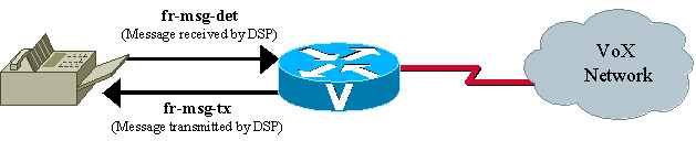
This debug shows the T.30 events that take place in the DSP within fax relay. It is important to remember
that the debugs that take place from the perspective of the DSP interact with the fax device, so any "Fr-
MSG-TX" or transmit message is transmitted from the DSP to the connected fax device. Any message that
the DSP says that it detects, or "fr-msg-det" message, is a message that it received from the connected fax
device. This graphic illustrates the directional flow of the DSP messages when the debug fax relay t30 all
command is issued.
From the failed fax transaction in the debug, you can see several "bad crc" messages followed by a Failure
To Train (FTT) message from the far side. From the debugs, it looks as if the problem involves the training
signal. The bad crc errors and the FTT (Failure To Train) message returned from the other side indicate that
the signal is corrupted or incompatible with the Cisco fax relay protocol. This debug is taken from a fax
relay problem that occurs with a Lexmark Optra fax machine. The Lexmark is V.34 capable and attempts to
connect at V.34 rates. V.34 is not supported in Cisco fax relay, and training errors occur. See Cisco bug ID
CSCdv89496 (registered customers only) for more details.
The Working Examples of T.30 Debugs page provides more information about how to read these debugs
and an example of a successful debug and ECM mode fax analyzer trace.
Debug vtsp all
There are also other debug commands that can be useful to troubleshoot fax relay problems. These debugs
are not as easy to read or provide as much information as the T.30 debugs, but they can still be useful.
Voice Telephony Service Provider (VTSP) is an architecture that defines the interface between the Cisco
IOS call control and a DSP end point connected to standard telephony equipment such as a PBX, fax, or
central office through analog or digital interfaces.
For VoIP T.38 or fax relay, debug vtsp all can provide useful state information from the router. As
discussed in of the troubleshooting section, this debug command can be used to determine if the fax codec
Page 29
has been downloaded into the DSP as shown on the Voice Telephony Service Provider Debugging page.
Debug vtsp vofr subframe 3
Another fax relay debug command that is helpful for fax with VoFR and VoATM is debug vtsp vofr
subframe 3. This command outputs FRF11 frames that have an Annex D fax relay payload type. There is a
significant amount of output from this command even with just one fax relay call, and the hex must be
decoded (the FRF11 specification is helpful for hex decoding).
Additional Debug Commands
To debug T.38 capabilities exchange issues, use the debug cch323 h245 command.
1.
To debug DSP message exchanges between applications and the DSP, use these debug commands:
debug vtsp all
•
debug voip ccapi inout
•
debug hpi all (on the Cisco 5300/2600/3600 and all other voice platforms that use the TI c54x
DSPs)
•
debug nextport vsmgr detail (on the NextPort DSP platforms (Cisco 5400, 5850))
•
2.
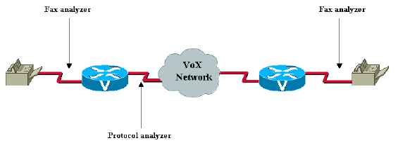
Fax Analyzers
Sometimes it is necessary to go beyond the debugging capabilities of the Cisco voice gateways to resolve
fax relay problems. Tools such as protocol analyzers and fax analyzers are used to see what occurs in fax
relay operation. Fax analyzers such as the Genoa ChannelProbe/FaxProbe by QualityLogic or the HP
Telegra can be positioned between the fax device and the Cisco gateway to capture what occurs. Protocol
analyzers such as Sniffer and Domino can be helpful when you need to view the fax relay packets that are
exchanged between the routers.
The ability to resolve a complex problem sometimes requires a combination of equipment—an analyzer to
capture the fax traffic at each fax machine and a protocol analyzer to capture the fax relay packets. A single
fax call is placed to reproduce the problem, and then the information is captured from the attached devices
for analysis. This diagram shows where in the network this test equipment is placed.
Most of the fax analyzers have adequate help screens and documentation to help you determine what
Page 30
happens. The T.30 specification is also very helpful. For the protocol analyzers, decoding can be difficult
because sometimes the encodings are proprietary, or the analyzer software does not have the specific decode
needed. For fax relay that uses VoFR and VoATM, Cisco gateways use standards-based Annex D from the
FRF11 specification. If the protocol analyzer is not able to decode the frame, the frame can be manually
decoded with this specification. With fax relay and VoIP, a Cisco proprietary format is used for the fax relay
packets.
With fax analyzer and protocol analyzer information, you are able to resolve fax relay problems. Few fax
relay problems reach this point, and when they do, escalation and DE resources must be involved for further
assistance.
In addition, provide all other information relevant to the problem.
Open a TAC Case
If this document has not enabled you to isolate and resolve the problem, open a case with the Cisco
Technical Assistance Center (TAC) and provide this information:
Network topology description (PDF, Visio, or Microsoft PowerPoint format).
•
The fax machines used, which include vendor and model information.
•
The history of the problem.
Useful information includes whether the implementation is new or an established network that worked
well and then failed. If the network was established, what changed before the problem occurred? Is
the problem intermittent? Can the problem be reproduced, and, if so, what are the steps needed to
reproduce the problem?
•
Output of the show tech command from both fax gateways and all the routers on the IP path, and
relevant information for the active non-Cisco network equipment.
•
A pair of the call traces with these debug flags enabled:
debug voip ccapi inout
○
debug vtsp all
○
debug isdn q931 (if the ISDN or Q.Sig is involved)
○
•
A pair of the show voice call and show voice dsp outputs.
•
A pair of the fax analyzer traces connected in the monitor mode to the origination and termination fax
machines, if available.
•
Results of the troubleshooting and debugs performed, if available.
•
Related Information
originally published to https://www.cisco.com/c/en/us/support/docs/voice/fax-modem-over-ip/20227-
faxrelay-tsguide.html
original MDF tag is: Technologies:Voice:Fax / Modem over IP.
Document ID is 20227
Page 31
If the Document ID or URL do not match, contact tz-writers@cisco.com.
Cisco Voice over IP Solutions - Fax Services
•
Configuring VoIP Fax Relay Using Call Manager and a Voice Gateway
•
Cisco IOS Fax and Modem Services over IP Application Guide
•
Faxing over IP Using Catalyst 6608 and VG248
•
H.323 T.38 Fax Relay Issues
•
Cisco AVVID Gateway Support for Fax Relay and Fax Pass-Through
•
Voice - Configuring Fax Relay with VoIP ( T.38)
•
Voice Technology Support
•
Unified Communications Product Support
•
Recommended Reading: Troubleshooting Cisco IP Telephony
•
Technical Support & Documentation - Cisco Systems
•