Document Metadata
Format: PDF
Title: Understanding Jitter in Packet Voice Networks (Cisco IOS Platforms)
Page 1
Understanding Jitter in Packet Voice Networks
(Cisco IOS Platforms)
Document ID: 18902
Contents
Introduction
Prerequisites
Requirements
Components Used
Conventions
Jitter in Packet Voice Networks
Determine the Severity of Jitter
What Causes Jitter?
Encapsulation Considerations
Jitter in a Frame Relay Environment
Conclusion
Related Information
Introduction
This document describes jitter, and how to measure and compensate for it.
Prerequisites
Requirements
Readers of this document should have knowledge of these topics:
Basic Cisco IOS® voice configuration
•
Basic understanding of Quality of Service (QoS)
•
Components Used
The information in this document is applicable to Cisco IOS voice gateways and routers.
The information in this document was created from the devices in a specific lab environment. All of the
devices used in this document started with a cleared (default) configuration. If your network is live, make sure
that you understand the potential impact of any command.
Conventions
For more information on document conventions, refer to the Cisco Technical Tips Conventions.
Jitter in Packet Voice Networks
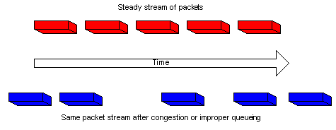
Jitter is defined as a variation in the delay of received packets. At the sending side, packets are sent in a
continuous stream with the packets spaced evenly apart. Due to network congestion, improper queuing, or
Page 2
configuration errors, this steady stream can become lumpy, or the delay between each packet can vary instead
of remaining constant.
This diagram illustrates how a steady stream of packets is handled.
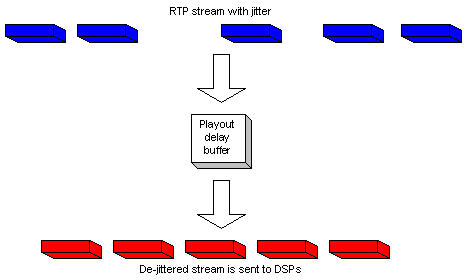
When a router receives a Real−Time Protocol (RTP) audio stream for Voice over IP (VoIP), it must
compensate for the jitter that is encountered. The mechanism that handles this function is the playout delay
buffer. The playout delay buffer must buffer these packets and then play them out in a steady stream to the
digital signal processors (DSPs) to be converted back to an analog audio stream. The playout delay buffer is
also sometimes referred to as the de−jitter buffer.
This diagram illustrates how jitter is handled.
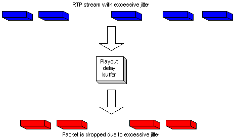
If the jitter is so large that it causes packets to be received out of the range of this buffer, the out−of−range
packets are discarded and dropouts are heard in the audio. For losses as small as one packet, the DSP
interpolates what it thinks the audio should be and no problem is audible. When jitter exceeds what the DSP
can do to make up for the missing packets, audio problems are heard.
This diagram illustrates how excessive jitter is handled.
Page 3
Determine the Severity of Jitter
The presence of excessive jitter can be confirmed through Cisco IOS by completing these steps.
Once a call is up and active, and jitter is suspected, Telnet to one of the gateways involved.
1.
Enable Terminal Monitor in order to be able to see console messages through your Telnet session.
Note: This step is not necessary if you are connected to the console port.
2.
Enter the show voice call summary command. Output similar to this appears:
PORT CODEC VAD VTSP STATE VPM STATE
============ ======== === ==================== ======================
1/0/0 − − − FXSLS_ONHOOK
1/0/1 g729r8 y S_CONNECT FXSLS_CONNECT
Select the call where the jitter is experienced. In this example, it is 1/0/1.
3.
To look at this specific call, enter the show voice call command.
In this example, it is show voice call 1/0/1. The output that is given comes from the DSP that handles
the call and is similar to this:
1/0/1 vtsp level 0 state = S_CONNECT
vpm level 1 state = FXSLS_CONNECT
vpm level 0 state = S_UP
MS−2621−3B# DSP VOICE VP_DELAY STATISTICS
Clk Offset(ms): 0, Rx Delay Est(ms): 50
Rx Delay Lo Water Mark(ms): 50, Rx Delay Hi Water Mark(ms): 7
DSP VOICE VP_ERROR STATISTICS
Predict Conceal(ms): 0, Interpolate Conceal(ms): 0
Silence Conceal(ms): 0, Retroact Mem Update(ms): 0
Buf Overflow Discard(ms): 0, Talkspurt Endpoint Detect Err: 0
DSP VOICE RX STATISTICS
Rx Vox/Fax Pkts: 1187, Rx Signal Pkts: 0, Rx Comfort Pkts: 0
Rx Dur(ms): 150200, Rx Vox Dur(ms): 23740, Rx Fax Dur(ms): 0
Rx Non−seq Pkts: 0, Rx Bad Hdr Pkts: 0
Rx Early Pkts: 0, Rx Late Pkts: 0
DSP VOICE TX STATISTICS
Tx Vox/Fax Pkts: 7129, Tx Sig Pkts: 0, Tx Comfort Pkts: 0
Tx Dur(ms): 150200, Tx Vox Dur(ms): 14259, Tx Fax Dur(ms): 0
4.
Page 4
DSP VOICE ERROR STATISTICS
Rx Pkt Drops(Invalid Header): 0, Tx Pkt Drops(HPI SAM Overflow): 0
DSP LEVELS
TDM Bus Levels(dBm0): Rx −54.5 from PBX/Phone, Tx −64.7 to PBX/Phone
TDM ACOM Levels(dBm0): +2.0, TDM ERL Level(dBm0): +9.9
TDM Bgd Levels(dBm0): −49.4, with activity being voice
View the DSP VOICE VP_ERROR STATISTICS section in the output.
Under this section, there are several parameters to look at. The main one is the number of Buf
Overflow Discard (ms) that are seen. This counts the packets that are out of range for the
playout delay buffer (dropped). This may have some value in it, as long as it does not constantly
increase. It is normal to get some overflows when a call is first initiated, but this value should not
increase when the show voice call X/X/X command is repeated. This number is a direct indication of
excessive jitter.
By default, this buffer runs in an adaptive mode where it dynamically adjusts to the amount of jitter
present (up to a point). Configure the playout−delay command to change the defaults for the dynamic
behavior of the de−jitter buffer. This buffer can also be set in fixed mode. This can fix some issues
with jitter. For more information, refer to Playout Delay Enhancements for Voice over IP.
5.
What Causes Jitter?
Jitter is generally caused by congestion in the IP network. The congestion can occur either at the router
interfaces or in a provider or carrier network if the circuit has not been provisioned correctly.
Encapsulation Considerations
The easiest and best place to start looking for jitter is at the router interfaces since you have direct control over
this portion of the circuit. How you track down the source of the jitter depends greatly on the encapsulation
and type of link where the jitter happens. Typically, ATM circuits do not experience jitter when configured
correctly due to the constant cell rate involved. This gives a very consistent latency. If jitter is seen in an ATM
environment, examination of the ATM configuration is necessary. When ATM works correctly (no dropped
cells), you can expect jitter to be a non−issue. In Point−to−Point Protocol (PPP) encapsulation, jitter is almost
always due to serialization delay. This can easily be managed with Link Fragmentation and Interleaving on
the PPP link. The nature of PPP means that PPP endpoints talk directly to each other, without a network of
switches between them. This is so that the network administrator has control over all interfaces involved.
Jitter in a Frame Relay Environment
Three parameters need to be addressed to find the jitter in a Frame Relay environment:
Traffic Shaping
•
Fragmentation
•
Queueing
•
For sample configurations and information related to configuring this, refer to VoIP over Frame Relay with
Quality of Service.
Traffic Shaping
You need to ensure that you are shaping the traffic that leaves the router to the actual Committed Information
Rate (CIR) that the carrier provides. Verify this by looking at the Frame Relay statistics and check with the
carrier. The first place to look is at the Frame Relay statistics. Use the show frame−relay pvc xx command ,
where xx is the Data−link connection identifier (DLCI) number. You should receive output similar to this:
Page 5
PVC Statistics for interface Serial0/1 (Frame Relay DTE)
DLCI = 16, DLCI USAGE = LOCAL, PVC STATUS = ACTIVE, INTERFACE = Serial0/1.1
input pkts 103611 output pkts 120054 in bytes 9909818
out bytes 10962348 dropped pkts 0 in FECN pkts 0
in BECN pkts 0 out FECN pkts 0 out BECN pkts 0
in DE pkts 0 out DE pkts 0
out bcast pkts 1366 out bcast bytes 448048
5 minute input rate 0 bits/sec, 0 packets/sec
5 minute output rate 0 bits/sec, 0 packets/sec
pvc create time 22:45:57, last time pvc status changed 22:45:57
Queueing strategy: weighted fair
Current fair queue configuration:
Discard Dynamic Reserved
threshold queue count queue count
64 16 0
Output queue size 0/max total 600/drops 18303
fragment type end−to−end fragment size 1600
cir 20000 bc 1000 be 0 limit 125 interval 50
mincir 20000 byte increment 125 BECN response no IF_CONG no
frags 103356 bytes 9807006 frags delayed 67241 bytes delayed 7127120
shaping active
traffic shaping drops 18303
Refer to the show frame−relay pvc description for a complete explanation of all fields.
What to Look For
What you should be concerned with in the command output are the values that show if there has been
congestion in the frame network. These values are the forward explicit congestion notification (FECN),
backward explicit congestion notification (BECN) and discard eligible (DE) parameters. You should be
concerned with only input packets since Cisco does not send any of these. You may see one or more of these
values incrementing. This depends on the type and configuration of the frame switches that the provider uses.
In general terms, if you have Frame Relay traffic shaping, and are configured for the same CIR as the circuit,
you should never see these values increment. If you do see these values increment, and you match the true
CIR of the circuit, something in the frame provider's network is not configured properly.
One good example of this is if you purchase a zero CIR circuit, but have a burst value. Some providers sell the
zero CIR permanent virtual circuit (PVC). This is fine for data, but causes problems with voice quality. If you
look at the command output from a zero CIR circuit, the number of DE or FECN packets equals the number
of input packets. To take this a step further, if you have a PVC that is provisioned by the carrier to be 128 kbs
and the CIR of the router is set to 512 kbs, you see these counters increment (at a slower rate). Remember that
you are only looking at packets that come into the router interface and that this rate is controlled by the
traffic−shaping parameters configured on the router at the opposite end of the PVC. Conversely, you control
what is input to the other router by which traffic−shaping parameters are configured on the local end.
It is very important that you not exceed the CIR for the PVC that is provisioned by the carrier. You can be
below this CIR without having problems. However, if you exceed it, you will see congestion.
The reason you are able to see the congestion in this fashion is because the CIR that is configured for a
specific PVC on a frame switch dictates the rate that traffic is passed by that switch (for that PVC). When the
configured CIR on the frame switch is exceeded by the actual data rate it receives, it must buffer the frames
that exceed the CIR until the capacity is available to forward the buffered packets. Any packet that is buffered
gets either the DE bit set or the FECN bit set by the frame switch.
As always, you also want to closely examine the interface statistics, and look for drops or errors to be sure that
everything functions correctly at the physical layer. To do this, use the show interface command.
Page 6
How this relates to jitter is if this occurs, and some packets need to be buffered in the frame network, they
have a longer latency in getting to the remote router. However, when there is no congestion, they get through
in the latency time that you normally expect. This causes a variation in the delta time between packets
received at the remote router. Hence, jitter.
Fragmentation
Fragmentation associates more with serialization delay than with jitter. However, under certain conditions, it
can be the cause of jitter. Fragmentation should always be configured in the Frame Relay map class when
doing packetized voice. The configuration of this parameter has two effects on the interface. The first effect is
that all packets larger than the size specified are fragmented. The second effect is less apparent, but is just as
important. If you look at the interface on which fragmentation is configured, you can see the effect of this
command. Without fragmentation, the queuing strategy shown in the output of the show interface x
command shows that first in first out (FIFO) queueing is in use. Once fragmentation is applied to the Frame
Relay map class, the output of this command shows the queueing strategy as dual−FIFO. This creates the
priority queue that is used for voice traffic on the interface. It is strongly suggested that the fragmentation
value be set to the values that are advised in the Fragmentation section of the VoIP over Frame Relay with
QoS document. If you still experience jitter problems at the recommended value, lower the fragmentation
value one step at a time until voice quality becomes acceptable.
Queueing
There are two generally accepted queueing methods used for VoIP traffic in this type of environment:
IP RTP Priority Queueing
•
Low Latency Queueing
•
One method or the other should be used, they should not both be configured. If the queueing operation looks
correct according to the documentation, then you can conclude that queueing works properly and the problem
lies elsewhere. Queuing is generally not a cause of jitter since the variations in delay created by it are
relatively small. However, if VoIP packets do not get queued properly and there is data on the same circuit,
jitter can result.
Conclusion
Jitter is a variation in packet latency for voice packets. The DSPs inside the router can make up for some jitter,
but can be overcome by excessive jitter. This results in poor voice quality. The cause of jitter is that a packet
gets queued or delayed somewhere in the circuit, where there was no delay or queueing for other packets. This
causes a variation in latency. Jitter can be caused both by router misconfiguration and by PVC
misconfiguration by the carrier or provider.
Related Information
Voice Technology Support
•
Voice and Unified Communications Product Support
•
Troubleshooting Cisco IP Telephony
•
Technical Support − Cisco Systems
•
Contacts & Feedback | Help | Site Map
© 2014 − 2015 Cisco Systems, Inc. All rights reserved. Terms & Conditions | Privacy Statement | Cookie Policy | Trademarks of
Cisco Systems, Inc.

Page 7
Updated: Feb 02, 2006
Document ID: 18902