Document Metadata
Format: PDF
Title: Troubleshooting QoS Choppy Voice Issues
Page 1
Troubleshooting QoS Choppy Voice Issues
Document ID: 20371
Contents
Introduction
Prerequisites
Requirements
Components Used
Conventions
Causes of Choppy Voice
Bandwidth Requirement
Voice Traffic Priority
Serialization Delay
VAD
Typical Configuration Examples for QoS
Jitter and Playout Mechanism
Playout Mechanism
Jitter Buffer
Identify Delay and Jitter
show call active voice
show voice call <port−number>
Configure Jitter Buffer on a Gateway
Playout−delay Mode
Related Information
Introduction
For Packet Voice to be a realistic replacement for standard public switched telephone network (PSTN)
Telephony services, the received quality of Packet Voice must be comparable to that of basic telephone
services. This means consistently high−quality voice transmissions. Like other real−time applications, Packet
Voice has a wide bandwidth and is delay sensitive. For voice transmissions to be intelligible (not choppy) to
the receiver, voice packets cannot be dropped, excessively delayed, or suffer varying delay (otherwise known
as jitter). This document describes various Quality of Service (QoS) considerations that help troubleshoot
choppy voice issues. The main reasons for choppy voice problems are lost and delayed voice packets.
Prerequisites
Requirements
Readers of this document should be knowledgeable of these:
Basic configuration of Packet Voice (VoIP, Voice over Frame Relay (VoFR) or Voice over ATM
(VoATM) as per their requirement).
•
Basic understanding of voice prioritization, fragmentation, different codecs and their bandwidth
requirements.
•
Components Used
The information in this document applies to all Cisco voice gateways software and hardware versions.
Page 2
The information presented in this document was created from devices in a specific lab environment. All of the
devices used in this document started with a cleared (default) configuration. If you are working in a live
network, ensure that you understand the potential impact of any command before using it.
Conventions
For more information on document conventions, refer to the Cisco Technical Tips Conventions.
Causes of Choppy Voice
Choppy voice quality is caused by voice packets being either variably delayed or lost in the network. When a
voice packet is delayed in reaching its destination, the destination gateway has a loss of real−time
information. In this event, the destination gateway must predict what the content of the missed packet can
possibly be. The prediction leads to the received voice not having the same characteristics as the transmitted
voice. This leads to a received voice that sounds robotic. If a voice packet is delayed beyond the prediction
capability of a receiving gateway, the gateway leaves the real−time gap empty. With nothing to fill up that
gap at the receiving end, part of the transmitted speech is lost. This results in choppy voice. Many of the
choppy voice issues are resolved by making sure that the voice packets are not very delayed (and more than
that, not variably delayed). Sometimes, voice activity detection (VAD) adds front−end clipping to a voice
conversation. This is another cause of choppy (or clipped) voice.
The various sections in this document show how to minimize the instance of choppy voice. Most of these
measures require assuring the introduction of minimum jitter in your voice network.
Bandwidth Requirement
Before you consider applying any measures for minimizing jitter, provision sufficient network bandwidth to
support real−time voice traffic. For example, an 80 kbps G.711 VoIP call (64 kbps payload + 16 kbps header)
sounds poor over a 64 kbps link because at least 16 kbps of the packets (which is 20 percent) are dropped. The
bandwidth requirements vary based on the codec used for compression. Different codecs have different
payloads and header requirements. Usage of VAD also affects the bandwidth requirement. If Real Time
Protocol (RTP) header compression (cRTP) is used, it can further lower the bandwidth requirement.
For example, the bandwidth required for a voice call using the G.729 codec (default 20 byte payload) with
cRTP, is like this:
Voice payload + compressed (RTP header + User Datagram Protocol (UDP) header + IP header)
+Layer 2 header
•
This is equivalent to:
20 bytes + compressed (12 bytes + 8 bytes + 20 bytes) + 4 bytes
•
This equals:
28 bytes, since the header compression reduces the IP RTP header to a maximum of 4 bytes. This
yields 11.2 kbps at an 8 kbps codec rate (50 packets per second).
•
For more information, refer to Voice over IP − Per Call Bandwidth Consumption.
Page 3
Voice Traffic Priority
There are two important components in prioritizing voice. The first is classifying and marking interesting
voice traffic. The second is prioritizing the marked interesting voice traffic. The two subsections here discuss
various approaches to classifying, marking, and prioritizing voice.
Classification and Marking
In order to guarantee bandwidth for VoIP packets, a network device must be able to identify the packets in all
the IP traffic that flows through it. Network devices use the source and destination IP address in the IP header,
or the source and destination UDP port numbers in the UDP header, to identify VoIP packets. This
identification and grouping process is called classification. It is the basis for providing any QoS.
Packet classification can be processor intensive. Therefore, classification needs to be done as far out towards
the edge of the network as possible. Because every hop still needs to make a determination on the treatment a
packet should receive, you need to have a simpler, more efficient classification method in the network core.
This simpler classification is achieved through marking or setting the Type of Service (ToS) byte in the IP
header. The three most significant bits of the ToS byte are called IP Precedence bits. Most applications and
vendors currently support setting and recognizing these three bits. Marking is evolving so that the six most
significant bits of the ToS byte, called the Differentiated Services Code Point (DSCP), can be used. Refer to
the Request for Comments (RFC).
Differentiated Services (DiffServ) is a new model in which traffic is treated by intermediate systems with
relative priorities based on the ToS field. Defined in RFC 2474
and RFC 2475
, the DiffServ standard
supersedes the original specification for defining packet priority described in RFC 791
. DiffServ increases
the number of definable priority levels by reallocating bits of an IP packet for priority marking. The DiffServ
architecture defines the DiffServ field. It supersedes the ToS byte in IP V4 to make Per−Hop Behavior (PHB)
decisions about packet classification and traffic conditioning functions such as metering, marking, shaping,
and policing. In addition to the previously mentioned RFCs, RFC 2597
defines the Assured Forwarding
(AF) classes. This is a breakdown of the DSCP fields. For more information on DSCP, refer to Implementing
Quality of Service Policies with DSCP.
ToS Byte − P2 P1 P0 T3 T2 T1 T0 CU
IP precedence: three bits (P2−P0), ToS: four bits (T3−T0), CU: one bit
DiffServ Field − DS5 DS4 DS3 DS2 DS1 DS0 ECN ECN
DSCP: six bits (DS5−DS0), ECN: two bits
XXX00000 Bits 0, 1, 2 (DS5, DS4, DS3) are Precedence bits, where:
111 = Network Control = Precedence 7
•
110 = Internetwork Control = Precedence 6
•
101 = CRITIC/ECP = Precedence 5
•
100 = Flash Override = Precedence 4
•
011 = Flash = Precedence 3
•
010 = Immediate = Precedence 2
•
001 = Priority = Precedence 1
•
000 = Routine = Precedence 0
•
000XXX00 Bits 3, 4, 5 (DS2, DS1, DS0) are Delay, Throughput, and Reliability bits.
Bit 3 = Delay [D] (0 = Normal; 1 = Low)
•

Page 4
Bit 4 = Throughput [T] (0 = Normal; 1 = High)
•
Bit 5 = Reliability [R] (0 = Normal; 1 = High)
•
000000XX Bits 6, 7: ECN
These two sections discuss two ways in which classification and marking are done.
Voice Dial Peers to Classify and Mark Packets
With Cisco VoIP gateways, you usually use voice dial peers to classify the VoIP packets and mark the IP
Precedence bits. This configuration shows how to mark the IP Precedence bits:
dial−peer voice 100 voip
destination−pattern 100
session target ipv4:10.10.10.2
ip precedence 5
In the example above, any VoIP call that matches the dial−peer voice 100 voip command has all of its voice
payload packets set with IP Precedence 5. This means that the three most significant bits of the IP ToS byte
are set to 101.
dial−peer voice 100 voip
destination−pattern 100
session target ipv4:10.10.10.2
ip qos dscp ef media
ip qos dscp af31 signaling
In the example above, any VoIP call that matches the dial−peer voice 100 voip command has all of its media
payload packets (voice packets) set with Expedited Forwarding (EF) bit pattern 101110. All the signaling
packets are set with AF bit pattern 011010.
Note: The ip qos dscp command is supported since Cisco IOS® Software Release 12.2(2)T. The IP
Precedence is no longer available in Cisco IOS Software Release 12.2T. However, the same is achieved by the
ip qos dscp command. IP precedence 5 (101) maps to IP DSCP 101000. For more information, refer to
Classifying VoIP Signaling and Media with DSCP for QoS.
Modular QoS CLI to Classify and Mark Packets
The recommended classification and marking method to use is the modular QoS CLI. This is a
template−based configuration method that separates the classification from the policy. This allows multiple
QoS features to be configured together for multiple classes. Use a class−map command to classify traffic
based on various match criteria and a policy−map command to determine what needs to happen to each class.
Apply the policy to incoming or outgoing traffic on an interface by issuing the service−policy command. This
configuration example shows how to use modular QoS CLI to classify and mark packets:
access−list 100 permit udp any any range 16384 32767
access−list 101 permit tcp any any eq 1720
!
class−map match−all voip
match access−group 100
class−map match−all control
match access−group 101
!
policy−map mqc
class voip
set ip precedence 5
class control
set ip precedence 5
Page 5
class class−default
set ip precedence 0
!
interface Ethernet0/0
service−policy input mqc
In this configuration example, any traffic that matches Access Control List (ACL) 100 is classified as "class
voip" and set with IP Precedence 5. This means that the three most significant bits of the IP ToS byte are set
to 101. ACL 100 matches the common UDP ports used by VoIP. Similarly ACL 101 matches H.323 signaling
traffic (Transmission Control Protocol (TCP) port 1720). All other traffic is set with IP Precedence 0. The
policy is called "mqc". It is applied to incoming traffic on Ethernet 0/0.
Prioritizing
After every hop in the network is able to classify and identify the VoIP packets (either through port/address
information or through the ToS byte), those hops then provide each VoIP packet with the required QoS. At
that point, configure special techniques to provide priority queuing to make sure that large data packets do not
interfere with voice data transmission. This is usually required on slower WAN links where there is a high
possibility of congestion. Once all the interesting traffic is placed into QoS classes based on their QoS
requirements, provide bandwidth guarantees and priority servicing through an intelligent output queuing
mechanism. A priority queue is required for VoIP.
Note: Use any queuing mechanism that effectively gives VoIP high priority. However, Low Latency
Queuing (LLQ) is recommended because it is flexible and easy to configure.
LLQ uses the modular QoS CLI configuration method to provide priority to certain classes and to provide
guaranteed minimum bandwidth for other classes. During periods of congestion, the priority queue is policed
at the configured rate so that the priority traffic does not use up all the available bandwidth. (If the priority
traffic monopolizes the bandwidth, it prevents bandwidth guarantees for other classes from being met.) If you
provision LLQ correctly, the traffic that goes into the priority queue should never exceed the configured rate.
LLQ also allows queue depths to be specified to determine when the router needs to drop packets if there are
too many packets that wait in any particular class queue. There is also a class−default command that is used
to determine treatment of all traffic not classified by a configured class. The class−default is configured with a
fair−queue command. This means that each unclassified flow is given an approximately equal share of the
remaining bandwidth.
This example shows how to configure LLQ. For more information, refer to Low Latency Queuing:
access−list 100 permit udp any any range 16384 32000
access−list 101 permit tcp any any eq 1720
access−list 102 permit tcp any any eq 80
access−list 103 permit tcp any any eq 23
!
class−map match−all voip
match access−group 100
class−map match−all voip−control
natch access−group 101
class−map match−all data1
match access−group 102
class−map match−all data2
match access−group 103
!
policy−map llq
class voip
priority 32
class voip−control
bandwidth 8
class data1
Page 6
bandwidth 64
class data2
bandwidth 32
class class−default
fair−queue
!
interface Serial1/0
bandwidth 256
service−policy output llq
In this example, any traffic that matches ACL 100 is classified as "class voip" (meaning voice traffic). It is
given a high priority up to 32 kbps. ACL 100 matches the common UDP ports used by VoIP. Access−list 101
matches the H.323 signaling traffic (TCP port 1720). Class data1 matches web traffic (TCP port 80 as seen in
Access List 102) and guarantees 64 kbps. Class data2 matches Telnet traffic (TCP port 23 as seen in ACL
103) and guarantees 32 kbps. The default class is configured to give an equal share of the remaining
bandwidth to unclassified flows. The policy is called "llq". It is applied to outgoing traffic on Serial1/0, which
has a total bandwidth of 256 kbps.
Note: By default, the total guaranteed bandwidth and priority bandwidth for all classes needs to be less than
75 percent of the interface bandwidth. Modify this percentage by issuing the max−reserved bandwidth
interface command.
This table compares different software queuing mechanisms with their respective benefits and limitations.
Software Queuing
Mechanism
Description
Benefits
Limitations
First−In−First−Out
(FIFO)
Packets arrive
and leave the
queue in
exactly the
same order.
Simple
configuration
and fast
operation.
No priority
servicing or
bandwidth
guarantees
possible.1
Weighted Fair
Queuing (WFQ)
A hashing
algorithm that
flows into
separate
queues where
weights are
used to
determine
how many
packets are
serviced at a
time. You
define
weights by
setting IP
Precedence
and DSCP
values.
Simple
configuration.
Default on
links less than
2 Mbps.
No priority
servicing or
bandwidth
guarantees
possible.1
Custom Queuing
(CQ)
Traffic is
classified into
multiple
queues with
configurable
Has been
available for a
few years. It
allows
approximate
No priority
servicing is
possible.
Bandwidth
guarantees are
Page 7
queue limits.
The queue
limits are
calculated
based on
average
packet size,
Maximum
Transmission
Unit (MTU),
and the
percentage of
bandwidth to
be allocated.
Queue limits
(in number of
bytes) are
de−queued
for each
queue.
Therefore it
provides the
allocated
bandwidth
statistically.
bandwidth
allocation for
different
queues.
approximate.
There are a
limited
number of
queues.
Configuration
is relatively
difficult.1
Priority Queuing
(PQ)
Traffic is
classified into
high,
medium,
normal, and
low priority
queues. The
high priority
traffic is
serviced first,
followed by
medium,
normal and
low priority
traffic.
Has been
available for a
few years. It
provides
priority
servicing.
Higher
priority traffic
starves the
lower priority
queues of
bandwidth. No
bandwidth
guarantees are
possible.2
Class−Based
Weighted Fair
Queuing (CBWFQ)
Modular QoS
CLI is used to
classify
traffic.
Classified
traffic is
placed into
reserved
bandwidth
queues or a
default
unreserved
queue. A
Similar to
LLQ, except
that there is no
priority queue.
Simple
configuration
and ability to
provide
bandwidth
guarantees.
No priority
servicing is
possible.3
Page 8
scheduler
services the
queues based
on weights so
that the
bandwidth
guarantees
are honored.
Priority Queue
Weighted Fair
Queuing
(PQ−WFQ), also
called IP RTP
Priority
A single
interface
command is
used to
provide
priority
servicing to
all UDP
packets
destined to
even port
numbers
within a
specified
range.
Simple, one
command
configuration.
Provides
priority
servicing to
RTP packets.
All other
traffic is
treated with
WFQ.
Real−Time
Conferencing
Protocol
(RTCP) traffic
is not
prioritized. No
guaranteed
bandwidth
capability.4
LLQ, previously
called Priority
Queue
Class−Based
Weighted Fair
Queuing
(PQCBWFQ)
Modular QoS
CLI with
priority queue
is used to
classify
traffic.
Classified
traffic is
placed into a
priority
queue,
reserved
bandwidth
queues, or a
default
unreserved
queue. A
scheduler
services the
queues based
on weights so
that the
priority traffic
is sent first
(up to a
certain
policed limit
during
congestion)
and the
Simple
configuration.
Ability to
provide
priority to
multiple
classes of
traffic and
give upper
bounds on
priority
bandwidth
utilization.
You can also
configure
bandwidth
guaranteed
classes and a
default class.
No
mechanism to
provide
multiple levels
of priority yet,
all priority
traffic is sent
through the
same priority
queue.
Separate
priority
classes can
have separate
upper priority
bandwidth
bounds during
congestion.
However,
sharing of
priority queue
between
applications
can potentially
introduce
jitter.4
Page 9
bandwidth
guarantees
are met.
Not suitable for voice.
1.
Needs bandwidth guaranteed for voice.
2.
Needs latency to be taken care of.
3.
Sufficient for voice.
4.
Serialization Delay
Even if queuing works at its best and prioritizes voice traffic, there are times when the priority queue is empty
and a packet from another class is serviced. Packets from guaranteed bandwidth classes must be serviced
based on their configured weight. If a priority voice packet arrives in the output queue while these packets are
being serviced, the voice packet can wait a significant amount of time before it is sent. Voice packets
experience serialization delay when they have to wait behind larger data packets.
Serialization delay can introduce the worst form of jitter for voice packets. If the voice packets have to wait
behind a data packet that is as large as 1500 bytes, on a slower link, this translates to a huge delay. The
serialization delay is vastly different if the data packet is 80 bytes, as shown in this example:
Serialization delay on a 64 kbps link due to a 1500 bytes packet = 15008/64000 = 187.5 ms.
•
Serialization delay on a 64 kbps link due to a 80bytes packet = 808/64000 = 10 ms.
•
Therefore, a voice packet potentially has to wait up to 187.5 ms before it is sent if it gets stuck behind a single
1500−byte packet on a 64 kbps link. On the other hand, another voice packet has to wait for only 10 ms at the
destination gateway. This results into a huge jitter that occurs due to the variance in the inter−packet delay.
On the originating gateway, voice packets are usually sent every 20 ms. With an end−to−end delay budget of
150 ms and strict jitter requirements, a gap of more than 180 ms is unacceptable.
Introduce a mechanism of fragmentation that ensures that the size of one transmission unit is less than 10 ms.
Any packets that have more than 10 ms serialization delay need to be fragmented into 10 ms chunks. A 10 ms
chunk or fragment is the number of bytes that is sent over the link in 10 ms. Calculate the size by using the
link speed, as shown in this example:
Fragmentation size = (0.01 seconds * 64,000 bps) / (8 bits/byte) = 80 bytes
•
It takes 10 ms to send an 80−byte packet or fragment over a 64 kbps link.
In case of multiple ATM or Frame Relay Permanent Virtual Circuits (PVCs) on a single physical interface,
configure fragmentation values (on all PVCs) based on the PVC that has the lowest bandwidth available. For
example, if there are three PVCs that have a guaranteed bandwidth of 512 kbps, 128 kbps, and 256 kbps, then
configure all three PVCs with a fragment size of 160 bytes (the lowest speed is 128 kbps that requires a
160−byte fragment size). These values are recommended for different link speeds:
Link Speed (kbps) Fragmentation Size (bytes)
56 70
64 80
128 160
256 320
512 640
768 960
1024 1280
1536 1920
Page 10
Note: No fragmentation is required if the fragment size is larger than the link MTU size. For example, for a
T1 link with a 1500−byte MTU, the fragment size is 1920 bytes. Therefore, no fragmentation is required. The
packet fragmentation size should never be lower than the VoIP packet size. Do not fragment VoIP packets.
Fragmenting these packets causes numerous call setup and quality issues.
There are currently three link fragmentation and interleaving mechanisms available. For further explanation of
various delays introduced in a packet network, refer to Understanding Delay in Packet Voice Networks. This
table lists their benefits and limitations:
Link
Fragmentation
and
Interleaving
(LFI)
Mechanism
Description
Benefits
Limitations
MTU
fragmentation
with WFQ
Interface level
command to
change MTU
size or IP MTU
size. Used to
fragment large
IP packets to
specified MTU
size. LFI uses
WFQ to
interleave
real−time
packets in
between the
fragments.
Simple
configuration.
Fragments are
reassemble only
by the receiving
application.
Therefore,
inefficient use of
the network.
Only IP packets
with the Do not
Fragment (DF)
bit not set can
handle
fragmentation
well. Highly
processor
intensive. Not
recommended.
Multilink
Point−to−Point
Protocol
(MLPPP) LFI
On
point−to−point
serial links,
MLPPP must
first be
configured, then
a fragmentation
size must be set
in ms.
Interleaving
must also be
enabled on the
multilink
interface.
Packets are
fragmented on
one end of the
link and
reassembled at
the other.
Several links
can be
combined to
act as a large
virtual pipe.
Only available
on links
configured for
PPP. Solutions
for PPP over
Frame Relay or
PPP over ATM
are also
supported in
Cisco IOS
Software
Release 12.1(5)T
or later.
Frame Relay
Fragmentation
(FRF.12)
On Frame Relay
PVCs, the
frame−relay
traffic−shaping
command must
be enabled and a
Packets are
fragmented on
one end of the
PVC and
reassembled at
the other.
Only available
on Frame Relay
PVCs with the
frame−relay
traffic−shaping
command
Page 11
fragmentation
size set under
the map−class.
enabled.
VAD
A regular voice conversation consists of several moments of silence. A typical voice conversation consists of
40 to 50 percent silence. Since there is not any voice going through the network for 40 percent of a voice call,
some bandwidth can be saved by deploying VAD. With VAD, the gateway looks out for gaps in speech. It
replaces those gaps with comfort noise (background noise). Thus, an amount of bandwidth is saved. However,
there is a trade−off. There is a small time (in order of milliseconds), before the codecs detect speech activity
followed by a period of silence. This small time results in the front−end clipping of received voice. To avoid
activation during very short pauses and to compensate for clipping, VAD waits approximately 200 ms after
speech stops before it stops transmission. Upon restarting transmission, it includes the previous 5 ms of
speech along with the current speech. VAD disables itself on a call automatically if ambient noise prevents it
from distinguishing between speech and background noise. However, if the bandwidth is not an issue, turn the
VAD off.
Tune VAD Parameters
There are two parameters that dictate the functioning of VAD. These are the music−threshold and voice
vad−time commands.
music−threshold
An initial threshold is decided which governs when VAD needs to become active. This is controlled by
defining the music−threshold threshold_value command on a voice−port, as shown in this example. The
range for this is from −70 Decibels Per Milliwatt (dBm) to −30 dBm. The default value for this is −38 dBm.
Configuring a lower value (towards −70 dBm) results in VAD becoming active at a much lower signal
strength (the volume must drop really low before it is considered as silence). Configuring a higher value
(closer to −30 dBm) results in VAD becoming active for even a small drop in voice signal strength. It drives
the playout to play comfort noise packets more often. However, this sometimes leads to minor clipping of
audio.
3640−6#configure terminal
Enter configuration commands, one per line. End with CNTL/Z.
3640−6(config)#voice−port 3/0/0
3640−6(config−voiceport)#music−threshold ?
WORD Enter a number b/w (−70 to −30)
3640−6(config−voiceport)#music−threshold −50
3640−6(config−voiceport)#end
3640−6#
3640−6#show run | be voice−portvoice−port 3/0/0 music−threshold −50
voice vad−time
Once the VAD becomes active, the component of background noise and comfort noise is controlled by
configuring the voice vad−time timer_value command under the global configuration, as shown in this
example. This is the delay time in milliseconds for silence detection and suppression of voice packet
transmission. The default value for the holdover time is 250 msec. This means that within 250 msec, comfort
noise begins. The range for this timer is 250 msec to 65536 msec. If a high value is configured for this,
comfort noise comes into play much later (background noise continues to be played). If this is configured for
65536 msec, then the comfort noise is turned off. A higher value for this timer is desired for smoother
transition between background noise and comfort noise. The downside to configuring the voice vad−time
command to a high level is that it does not achieve the desired 30 to 35 percent bandwidth saving.
Page 12
3640−6#
3640−6#
3640−6#configure terminal
Enter configuration commands, one per line. End with CNTL/Z.
3640−6(config)#voice vad−time ?
<250−65536> milliseconds
3640−6(config)#voice vad−time 750
3640−6(config)#end
3640−6#
3640−6#
3640−6#
3640−6#show run | be vad−time voice vad−time 750
Typical Configuration Examples for QoS
A typical scenario for setting up VoIP calls is either over a frame−relay link or over a PPP link. These are
configuration examples for these scenarios.
VoIPoFR − QoS Configuration Example
In this example (which contains only relevant sections of the configuration), it is assumed that the
frame−relay circuit speed is 256 kbps. The guaranteed Committed Information Rate (CIR) on PVC 100 is 64
kbps and on PVC 200 is 192 kbps. PVC 100 is used to carry both data and voice. PVC 200 is used only to
carry data. A maximum of four simultaneous voice calls exists at any given time. Configure fragmentation on
both PVCs based on the CIR of the lowest−bandwidth−voice−PVC (PVC carrying voice). Based on the
examples in this document, that means the fragmentation size is decided based on PVC 100's CIR (which is
64 kbps). As shown in the table of the Serialization Delay section, for a 64 kbps link, a fragmentation size of
80 bytes is required. The same fragmentation size needs to be configured for PVC 200.
For further details about the configuration of VoIP over Frame Relay, refer to VoIP over Frame Relay with
Quality of Service (Fragmentation, Traffic Shaping, LLQ / IP RTP Priority).
3660−1#show run
Building configuration...
!
class−map match−any voip
match ip rtp 16384 16383
match ip dscp 26 46
class−map match−all voip−control
match access−group 101
!
!
policy−map VoIPoFR
class voip
priority 48
class voip−control
bandwidth 8
class class−default
fair−queue
!
voice call send−alert
voice rtp send−recv
!
!
interface Serial4/0:0
bandwidth 256
no ip address
encapsulation frame−relay
frame−relay traffic−shaping
!
interface Serial4/0:0.1 point−to−point
bandwidth 64
Page 13
ip address 10.10.10.10 255.255.255.0
frame−relay ip rtp header−compression
frame−relay interface−dlci 100
class voice
!
interface Serial4/0:0.2 point−to−point
bandwidth 192
ip address 20.20.20.20 255.255.255.0
frame−relay interface−dlci 200
class data
!
map−class frame−relay data
frame−relay fragment 80
frame−relay adaptive−shaping becn
frame−relay cir 256000
frame−relay bc 32000
frame−relay be 0
frame−relay mincir 192000
frame−relay fair−queue
!
map−class frame−relay voice
frame−relay fragment 80
no frame−relay adaptive−shaping
frame−relay cir 64000
frame−relay bc 640
frame−relay be 0
frame−relay mincir 64000
service−policy output VoIPoFR
!
!
access−list 101 permit tcp any any eq 1720
!
!
voice−port 3/1/0
!
voice−port 3/1/1
!
!
dial−peer voice 10 voip
incoming called−number .
destination−pattern 1408.......
session target ipv4:10.10.10.11
dtmf−relay h245−signal h245−alphanumeric
no vad
!
dial−peer voice 20 pots
destination−pattern 1234
port 3/1/0
!
dial−peer voice 21 pots
destination−pattern 5678
port 3/1/1
VoIP Over PPP − QoS Configuration Example
In this example (which contains only relevant sections of the configuration), it is assumed that the QoS needs
to be configured for a point−to−point fractional T1 controller (that has twelve channels). A maximum of four
simultaneous voice calls exists at any given time. The configuration task involves configuring this serial
interface with PPP encapsulation, making it part of a multilink group, creating a multilink interface (that
belongs to the same multilink group), and configuring all the QoS on the multilink interface. For further
details about the configuration of VoIP over PPP, refer to VoIP over PPP Links with Quality of Service (LLQ
/ IP RTP Priority, LFI, cRTP).
3660−1#show run
Page 14
Building configuration...
!
class−map match−any voip
match ip rtp 16384 16383
match ip dscp 26 46
class−map match−all voip−control
match access−group 101
!
!
policy−map VoIPoPPP
class voip
priority 48
class voip−control
bandwidth 8
class class−default
fair−queue
!
voice call send−alert
voice rtp send−recv
!
!
interface Multilink7
bandwidth 768
ip address 10.10.10.10 255.255.255.0
ip tcp header−compression iphc−format
service−policy output VoIPoPPP
no cdp enable
ppp multilink
ppp multilink fragment−delay 10
ppp multilink interleave
multilink−group 7
ip rtp header−compression iphc−format
!
!
interface Serial4/0:0
bandwidth 768
no ip address
encapsulation ppp
no fair−queue
ppp multilink
multilink−group 7
!
!
access−list 101 permit tcp any any eq 1720
!
voice−port 3/1/0
!
voice−port 3/1/1
!
!
dial−peer voice 10 voip
incoming called−number .
destination−pattern 1408.......
session target ipv4:10.10.10.11
dtmf−relay h245−signal h245−alphanumeric
no vad
!
dial−peer voice 20 pots
destination−pattern 1234
port 3/1/0
!
dial−peer voice 21 pots
destination−pattern 5678
port 3/1/1
!
Page 15
Jitter and Playout Mechanism
There are always some uncontrolled entities in a network that contribute towards further delays and jitter in
the received voice packets. By modifying the jitter buffer on the terminating gateway the uncontrolled jitter is
resolved in the voice network.
Playout Mechanism
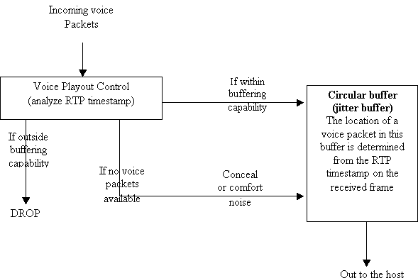
The jitter buffer is a time buffer. It is provided by the terminating gateway to make the playout mechanism
more effective. This is a functional diagram of the playout mechanism:
When the playout control receives a voice packet, it analyzes the RTP timestamp. If the voice packet is
delayed beyond the holding capacity of the jitter buffer, then the packet is immediately dropped. If the packet
is within the buffering capability, it is placed in the jitter buffer. The location of this packet in the jitter buffer
depends on the RTP timestamp calculated for that packet. In the event there is no available voice packet, the
playout control tries to conceal it (predicts the missed out packet). If VAD is enabled, comfort noise is played.
The responsibility of the playout control is to handle the events of lost packets, duplicated packets, corrupted
packets, and out−of−sequence packets. These events are handled by time aligning the jittered voice packets,
playing comfort noise (if VAD is configured), or even regenerating dual tone multifrequency (DTMF) tones
to be played out to the host.
The concealment of a voice packet is done by either prediction concealment or by silence concealment.
Prediction concealment is based on the previous packet and the next packet (if available). It works best with
low bitrate codecs (5 kbps to 16 kbps). Loss of voice packets for a high bitrate codec (32 kbps to 64 kbps) can
potentially result in poor prediction concealment. Prediction concealment starts when there are low and
infrequent delays or a lesser number of packet loss. Too much prediction concealment can lead to robotic
voice quality. Silence concealment is the worst form of prediction concealment. It comes into play when there
is no information available to predict. It is simply a background concealment. It starts when there are high
delays and more number of packet loss. Too much silence concealment leads to choppy voice quality. The
prediction concealment is good for 30 msecs after which the silence conceal comes into play.
Page 16
Jitter Buffer
The jitter buffer is confined by a high water mark and a low water mark. The high water mark is the upper
time limit within which a packet is expected to arrive for on−time playout. Packets that arrive after the high
water mark are marked as late packets or lost packets. The low water mark is the minimum time within which
a packet is expected to arrive for on−time playout. Packets that arrive before the low water mark are
considered early packets (it can still be played out on time).
If the terminating gateway continues to see an increment in the arrival of late packets, it increases the high
water mark. This value for high water mark remains the same throughout the duration of the call. This is
increased up to a maximum defined in the configuration. In a similar manner, the terminating gateway
observes the number of early packets received. If these packets start to frequent the gateway, it reduces the
low water mark. This value remains the same throughout the duration of the call. This mode of jitter buffer is
referred to as "adaptive mode," where the terminating gateway adapts its jitter buffer based on the traffic
pattern. The other mode is "fixed mode." In the fixed mode, there is one initial value for the low water mark
and the high water mark. This value is based on the estimated received delay ( see the show voice call
<port−number> section of this document).
For further details on jitter buffer, refer to Understanding Jitter in Packet Voice Networks (Cisco IOS
Platforms).
Identify Delay and Jitter
This section describes how to identify jitter in your network.
show call active voice
The show call active voice brief command gives a great deal of information about an ongoing conversation.
This output displays some important points that are learned from this command:
11E4 : 2170927hs.1 +600 pid:10 Answer 1000 active
dur 00:08:43 tx:26157/522967 rx:7044/139565
Tele 3/0/0:9: tx:151310/755/0ms g729r8 noise:−62 acom:0 i/0:−56/−48 dBm
11E4 : 2171198hs.1 +329 pid:20 Originate 2000 active
dur 00:08:43 tx:7044/139565 rx:26165/523127
IP 30.30.30.29:18682 rtt:51ms pl:148590/290ms lost:0/0/15 delay:65/60/132ms g729r8
From the show call active voice brief command output, you see that whatever is received on the Telephony
leg (rx:7044) is transmitted to the IP leg (tx:7044). The same is true for packets received on the IP legs
(26165) that are forwarded to the Telephony leg (26157). The difference in the number of packets received on
the IP leg versus the number of packets transmitted on the Telephony leg is contributed to late packets that do
not make it in time.
This output of the show call active voice command (without the "brief" keyword), points to further details
about parameters that directly identify jitter.
GapFillWithSilence=850 ms
GapFillWithPrediction=9230 ms
GapFillWithInterpolation=0 ms
GapFillWithRedundancy=0 ms
show voice call <port−number>
The show voice call port−number command provides useful information. Make sure to be either consoled in
Page 17
the gateway, or if you are Telneted into a gateway, make sure you have issued the terminal monitor
command from the exec level.
Note: This command is not available on the AS5x00/AS5x50 platforms.
In this output, the value for Rx Delay Est (ms) is 71. This is the current jitter buffer value. A value for the high
water mark and low water mark is deduced on this. An average initial value for the high water mark is 70
msec, while that for the low water mark is 60 msec. Once an initial value is set, the gateway keeps track of
any early packets or late packets received. As is seen in the output here, the prediction concealment drops are
close to 250 ms, while the silence concealment are 30 ms. There is always a higher value for prediction
concealment since silence concealment is only a worse case scenario of Prediction concealment. For every
Prediction concealment drop, there is an increase in the buffer overflow discard.
If you see buffer discard, it does not necessarily mean that you see an increase in the high water mark. The
high water mark is the upper limit of the jitter buffer. It changes only if a trend is observed. In other words,
there should be a continuous flow of late packets. This results in an increase of the jitter buffer. In the output
here, such a trend is present. Therefore, the high water mark is increased from 70 msec to 161 msec. If this
value is not changed (and if you still see 14 late packets), it implies that these are sporadic late packets, not
forming a trend.
From the output of the show call active voice command, look out for lost packets. For every lost packet, you
see two packets that are out of sequence. This is seen on the Rx Non−Seq Pkts output. Since it is not a
positive value, it is concluded that there has not been any packet losses either.
3640−6# DSP VOICE TX STATISTICS
Tx Vox/Fax Pkts: 195, Tx Sig Pkts: 0, Tx Comfort Pkts: 10
Tx Dur(ms): 192070, Tx Vox Dur(ms): 388, Tx Fax Dur(ms): 0
DSP VOICE RX STATISTICS
Rx Vox/Fax Pkts: 9604, Rx Signal Pkts: 0, Rx Comfort Pkts: 0
Rx Dur(ms): 192070, Rx Vox Dur(ms): 191560, Rx Fax Dur(ms): 0
Rx Non−seq Pkts: 0, Rx Bad Hdr Pkts: 0
Rx Early Pkts: 0, Rx Late Pkts: 14
DSP VOICE VP_DELAY STATISTICS
Clk Offset(ms): 0, Rx Delay Est(ms): 71
Rx Delay Lo Water Mark(ms): 60, Rx Delay Hi Water Mark(ms): 161
DSP VOICE VP_ERROR STATISTICS
Predict Conceal(ms): 250, Interpolate Conceal(ms): 0
Silence Conceal(ms): 30, Retroact Mem Update(ms): 0
Buf Overflow Discard(ms): 500, Talkspurt Endpoint Detect Err: 0
DSP LEVELS
TDM Bus Levels(dBm0): Rx −49.9 from PBX/Phone, Tx −41.7 to PBX/Phone
TDM ACOM Levels(dBm0): +2.0, TDM ERL Level(dBm0): +11.1
TDM Bgd Levels(dBm0): −58.9, with activity being voice
DSP VOICE ERROR STATISTICS
Rx Pkt Drops(Invalid Header): 0, Tx Pkt Drops(HPI SAM Overflow): 0
Observe the Tx Comfort Pkts and Rx Comfort Pkts. As from the example outputs, it is concluded that the
phone connected to this router mostly keeps quiet since you have lots of Tx Comfort Pkts. At the same time,
you have zero Rx Comfort Pkts, which means that the other end continuously speaks.
Compare the output here with the previous command output. There is an increased number of Rx Late Pkts
(from 14 to 26). However, there is no increment in the high water mark value. This indicates that the 12
packets are sporadically delayed. The Buffer Overflow discard is increased to 910 msecs. However, since
there is no trend observed, the high water mark is not increased.
In the output here, you have a Rx Early Pkts: 3. This means that a packet arrives much before it is expected.
As seen from the output here, the Jitter buffer has stretched itself to accommodate for any more early packets
by reducing the low water mark from 60 to 51.
Page 18
3640−6# DSP VOICE TX STATISTICS
Tx Vox/Fax Pkts: 209, Tx Sig Pkts: 0, Tx Comfort Pkts: 11
Tx Dur(ms): 337420, Tx Vox Dur(ms): 416, Tx Fax Dur(ms): 0
DSP VOICE RX STATISTICS
Rx Vox/Fax Pkts: 16843, Rx Signal Pkts: 0, Rx Comfort Pkts: 1
Rx Dur(ms): 337420, Rx Vox Dur(ms): 335920, Rx Fax Dur(ms): 0
Rx Non−seq Pkts: 0, Rx Bad Hdr Pkts: 0
Rx Early Pkts: 3, Rx Late Pkts: 26
DSP VOICE VP_DELAY STATISTICS
Clk Offset(ms): 0, Rx Delay Est(ms): 72
Rx Delay Lo Water Mark(ms): 51, Rx Delay Hi Water Mark(ms): 161
DSP VOICE VP_ERROR STATISTICS
Predict Conceal(ms): 510, Interpolate Conceal(ms): 0
Silence Conceal(ms): 70, Retroact Mem Update(ms): 0
Buf Overflow Discard(ms): 910, Talkspurt Endpoint Detect Err: 0
DSP LEVELS
TDM Bus Levels(dBm0): Rx −51.5 from PBX/Phone, Tx −44.1 to PBX/Phone
TDM ACOM Levels(dBm0): +2.0, TDM ERL Level(dBm0): +11.9
TDM Bgd Levels(dBm0): −61.3, with activity being voice
DSP VOICE ERROR STATISTICS
Rx Pkt Drops(Invalid Header): 0, Tx Pkt Drops(HPI SAM Overflow): 0
Configure Jitter Buffer on a Gateway
The QoS guidelines covered in this document take care of the choppy or deteriorated voice quality issue. The
configuration of playout−delay buffer is a workaround for improper QoS implementation in the network. Only
use this as a stop−gap fix or as a tool for troubleshooting and narrowing down of the jitter problems
introduced in the network.
Playout−delay Mode
The jitter buffer is configured for either fixed mode or adaptive mode. Under the adaptive mode, the gateway
allows you to configure a minimum value for the jitter buffer, a maximum value, and a nominal value. The
jitter buffer expects the packets to arrive within the nominal value range. The nominal value has to be either
equal to or more than the minimum, and equal to or less than the maximum. The buffer expands up to the
maximum value configured. This can extend up to 1700 msec. One issue with configuring high maximum
value is the introduction of end−to−end delay. Choose the value of maximum playout−delay such that it does
not introduce unwanted delay in the network. This output is an example of the jitter buffer configured for
adaptive mode:
3640−6#
3640−6#configure terminal
Enter configuration commands, one per line. End with CNTL/Z.
3640−6(config)#voice−port 3/0/0
3640−6(config−voiceport)#playout−delay mode adaptive
3640−6(config−voiceport)#playout−delay maximum 400
3640−6(config−voiceport)#playout−delay nominal 70
3640−6(config−voiceport)#playout−delay minimum low
3640−6(config−voiceport)#^Z
3640−6#
3640−6#
3640−6#show run | begin 3/0/0
voice−port 3/0/0
playout−delay maximum 400
playout−delay nominal 70
playout−delay minimum low
playout−delay mode adaptive
!
Under the fixed mode, the gateway looks at the configured value for nominal. Although it allows you to
Page 19
configure the minimum and the maximum value for playout−delay, it is ignored when configured for fixed
mode. When in the fixed mode, the high water mark value or the low water mark value always remains
constant. It is based on the nominal value and based on Rx Delay Est (ms) value. So it is possible that under
the fixed mode, you configure the value as 200 msec. However, if the estimated received delay is close to 100
ms, that is what the high water mark and the low water mark is set to for the entire duration of the call.
3640−6#
3640−6#configure terminal
Enter configuration commands, one per line. End with CNTL/Z.
3640−6(config)#voice−port 3/0/0
3640−6(config−voiceport)#playout−delay mode fixed
3640−6(config−voiceport)#playout−delay nominal 70
3640−6(config−voiceport)#^Z
3640−6#
3640−6#
3640−6#show run | begin 3/0/0
voice−port 3/0/0
playout−delay mode fixed
playout−delay nominal 70
!
For more details on the playout−delay configuration, refer to Playout Delay Enhancements for Voice over IP.
Related Information
Implementing Quality of Service Policies with DSCP
•
Low Latency Queueing
•
Comparing the bandwidth and priority Commands of a QoS Service Policy
•
Configuring Link Fragmentation and Interleaving for Frame Relay and ATM Virtual Circuits
•
Configuring Link Fragmentation and Interleaving for Multilink PPP
•
Voice Technology Support
•
Voice and Unified Communications Product Support
•
Troubleshooting Cisco IP Telephony
•
Technical Support − Cisco Systems
•
Contacts & Feedback | Help | Site Map
© 2014 − 2015 Cisco Systems, Inc. All rights reserved. Terms & Conditions | Privacy Statement | Cookie Policy | Trademarks of
Cisco Systems, Inc.
Updated: Feb 02, 2006
Document ID: 20371
