McDewey
/mcpPage 2
↗ View in doc contextThe PCM samples are then passed to the compression algorithm which compresses the voice into a
packet format for transmission across the WAN. On the far side of the cloud the exact same
functions are performed in reverse order. The entire flow is shown in Figure 2-1.
Figure 2-1 End-to-End Voice Flow
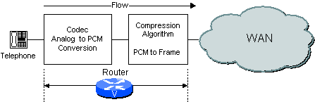
Based on how the network is configured, the router/gateway can perform both the codec and compression functions or only one of them. For example, if an analog voice system is used, then the router/gateway performs the CODEC function and the compression function as shown in Figure 2-2. Figure 2-2 Codec Function in Router/Gateway
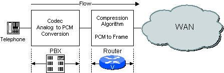
If a digital PBX is used, the PBX performs the codec function and the Router processes the PCM
samples passed to it by the PBX. An example is shown in Figure 2-3.
Figure 2-3 Codec Function in PBX
How Voice Compression Works
The high complexity compression algorithms used in Cisco router/gateways analyze a block of PCM
samples delivered by the Voice codec. These blocks vary in length based on the coder. For example,
the basic block size used by a G.729 algorithm is 10 ms whereas the basic block size used by the
G.723.1 algorithms is 30ms. An example of how a G.729 compression system works is shown in
Figure 3-1.
Page 2 of 18
Cisco - Understanding Delay in Packet Voice Networks
7/31/2008
http://kbase.cisco.com/paws/servlet/ViewFile/5125/delay-details.xml?convertPaths=1